

Page 1

WMTS T1 Access
Concentrator
V3000
Network Release 3.6
P/N: 3BR-0014A
System Configuration
Guide
Manual Version: 1.1.15
Page 2

Copyright and Trademark Information:
© 2005 Vyyo Inc. All rights reserved.
Vyyo Inc. reserves the right to alter the equipment specifications and descriptions in this publication without
prior notice. No part of this publication shall be deemed part of any contract or warranty unless specifically
incorporated by reference into such contract or warranty.
The information contained herein is merely descriptive in nature, and does not constitute a binding offer for
the sale of the product described herein. Any use of the Vyyo Inc. logo or trademarks is forbidden without
prior written approval from Vyyo Inc.
All trademarks mentioned herein are the property of their respective owners.
Page 3

Table Of Contents
Table Of Contents................................................................................ 3
Installation and Safety Information ...................................................... 7
Chapter 1. System Configuration Introduction.................................. 10
1.1 Overview...............................................................................................10
1.2 Equipment Capabilities.........................................................................13
1.3 WMTS...................................................................................................13
1.4 Modems................................................................................................16
1.4.1 Modems with DOCSIS and IP only................................................16
1.4.2 Modems with DOCSIS, IP and E1/T1............................................17
1.4.3 Modems with DOCSIS, IP and PSTN............................................18
1.4.4 Modems with DOCSIS and IP Only With Built in UHF Radio ........19
1.5 Modem Capabilities Matrix ...................................................................20
Chapter 2. Configuration Overview................................................... 21
2.1 Network Servers ...................................................................................21
2.1.1 DHCP Server.................................................................................21
2.1.2 TFTP Server..................................................................................21
2.1.3 Time-of-Day (TOD) Server ............................................................21
2.2 RF Link Layer .......................................................................................21
2.3 DOCSIS Layer......................................................................................22
2.4 IP Layer ................................................................................................23
2.5 E1/T1 Layer ..........................................................................................24
2.6 Configuration Tools and Files Matrix ....................................................26
Chapter 3. The Modem Initialization Process ................................... 28
3.1 Modem Initialization Sequence .....................................................28
3.1.1 Power-On Self Test ..........................................................................28
3.1.2 Downstream Synchronization.............................................................29
3.1.3 Obtaining Upstream Parameters ........................................................29
Page 4

www.vyyo.com
Table Of Contents – p. 4
3.1.4 Ranging ..........................................................................................29
3.1.5 Establish IP Connectivity ...................................................................29
3.1.6 Establish Time of Day .......................................................................30
3.1.7 Transfer Operational Parameters .......................................................30
3.1.8 Registration .....................................................................................30
3.1.9 Baseline Privacy Initialization (BPI).....................................................30
Chapter 4. Overview of the WMTS and Modem Configuration ........ 31
Chapter 5. Adding a Modem to the WMTS....................................... 34
5.1 Editing the Modem Configuration File...................................................35
5.1.1 Setting the Upstream Channel ......................................................35
5.1.2 Setting the Downstream Frequency ..............................................38
5.1.3 Setting Concatenation and Fragmentation Capabilities.................39
5.1.4 Setting Upstream QoS (Class of Service) for IP Data ...................40
5.1.5 Setting Additional Downstream and Upstream Channels ..............41
5.1.6 Setting the Maximum Number of CPEs .........................................42
5.2 DHCP Settings for the Modem .............................................................43
5.2.1 IpLease DHCP Server: Editing and running the CM.SRC File ......43
5.2.2 Windows 200x Server Edition: Modifying the DHCP Options .......48
5.3 Configuring the WMTS .........................................................................57
5.3.1 Setting the WMTS Upstream Parameters .....................................57
5.3.2 Setting the WMTS Downstream Parameters.................................60
5.4 Setting the Modem’s Downstream Frequency ......................................62
5.5 Verifying the Modem Downstream and Upstream Status .....................69
5.6 Using an HTTP Connection to View Modem Operation........................71
5.6.1 Viewing the internal modem HTML pages:....................................71
5.6.2 Viewing the Connection Page .......................................................73
5.6.3 Viewing the Software Page ...........................................................74
5.6.4 Viewing the Security Page.............................................................75
Chapter 6. Configuring a T1 Connection .......................................... 76
6.1 Configure the Modem for T1 Operation ................................................77
6.2 Adding the T1 modem to the WMTS T1 Interface and Assign Port(s) ..85
Page 5

www.vyyo.com
Table Of Contents – p. 5
Chapter 7. Setting the WMTS IP Address ........................................ 93
Chapter 8. Installing Vyyo Servers for WMTS Operation ............... 106
8.1 Installing The Time Server:.................................................................106
8.2 Installing the Pumpkin TFTP Server: ..................................................106
8.3 Installing IPLease DHCP Server:........................................................ 109
8.3.1 dhcpsvr.ini ...................................................................................109
8.3.2 cm.src..........................................................................................110
8.3.3 Dhcpgen ......................................................................................112
8.3.4 DhcpSvr:......................................................................................115
Chapter 9. Maintenance and Troubleshooting................................ 116
9.1 Introduction.........................................................................................116
9.2 Troubleshooting the RF Frontend.......................................................116
9.2.1 General........................................................................................116
9.2.2 Checking the Downstream ..........................................................117
9.2.3 Checking the Upstream ...............................................................118
Chapter 10. Troubleshooting The Subscriber Site ..................... 119
10.1 Post-Registration Verification .............................................................119
10.2 Physical Layer Troubleshooting.......................................................... 119
10.3 IF Layer Troubleshooting....................................................................119
10.4 Troubleshooting the NMS ...................................................................120
10.5 Repairs Safety ....................................................................................121
Appendix A. WMTS US Port Mapping ........................................ 122
Appendix B. Checking the WMTS Version.................................. 123
Appendix C. Installing and Uninstalling the NMS........................ 126
C.1 First Time Installation.......................................................................... 126
C.2 Launching the Vyyo NMS ...................................................................126
C.3 Installation Upgrade............................................................................126
C.4 Uninstalling the NMS ..........................................................................127
Appendix D. Launching the Vyyo Configuration Tool.................. 128
Page 6

www.vyyo.com
Table Of Contents – p. 6
D.1 The Vyyo Configuration Tool Menu (exploded view) ..............................129
D.2 Launching the Vyyo Configuration Tool from the “Start” Menu ............... 130
D.3 Launching the Vyyo Configuration Tool from the NMS ........................... 133
Appendix E: Vyyo Configuration Tool – Additional Functions ......... 136
E.1 Adding and Deleting a Modem ........................................................... 136
INDEX 137
Page 7

Installation and Safety Information
The following information is provided to ensure
safe operation of this equipment. Vyyo
assumes no liability in the event that the
customer fails to comply with the following
safety precautions and warnings.
System Power-on
AC System
DC System
AC System Power
The WMTS power supplies are factory wired for 115 ~ 220 VAC (2 X
200W). A power cords are provided to connect the unit to the power
source. To operate the WMTS, turn ON the power switch at the rear panel.
Warning!
Set the fuse selector on the rear panel to the proper position
(110V or 220V), before plugging in the power cord, or turning on the
WMTS.
DC System Power
1. When connecting DC power lines make sure to connect Ground line
first.
2. When disconnecting DC power lines – make sure to disconnect ground
last.
3.External Circuit Breaker (DuPole) should be used before
connection/removal of the power cable to/from the WMTS.
4. FUSE Replacement – Make sure to use same type and value fuse !
Note that UL requires use of AC ceramic high breaking capacity 10Amp
fuse.
Page 8

www.vyyo.com
Installation and Safety Information – p. 8
Earthing
General
The minimum cross sectional area of the protective
earthing should be 1mm2 .
T1 Cable
General
T1 cable to be used with WMTS T1 ports is only 26AWG
communication cable (the common cable for this application).
Repairs Safety
General
1. Repairs of WMTS should take place only in Vyyo company
service laboratories or in other Vyyo formally approved
distributors service laboratories.
2. In case of field handling - Disconnect the unit from power
supply for safest repair.
3. 2. In case of a -48VDC operated WMTS, the External Circuit Breaker
(Du Pole) must be used before connection/removal of the power cable
to/from the WMTS.
Page 9

www.vyyo.com
Installation and Safety Information – p. 9
Safety Summary
Warnings:
Carefully connect units to the supply circuit so that
wiring is not overloaded. For DC system connect
Ground first (or remove Ground last for disconnect).
Read the installation instructions before connecting
the system to its power source.
Secure all power cabling when installing this unit.
Do not touch the power supply when power cord is
connected. For systems with a power switch, line
voltages are present within the power supply, even
when the power switch is off and the power cord is
connected. For systems without a power switch, line
voltages are present within the power supply when the
power cord is connected
The device is designed to work with TN power
systems
Before working on equipment that is connected to
power lines, remove jewelry (including rings,
necklaces, and watches). Metal objects will heat up
when connected to the power and ground. This can
cause serious burns or weld the metal object to the
terminals
Repairs of WMTS should take place only in Vyyo
company service laboratories or in other Vyyo formally
approved distributors service laboratories. In case of
field handling our general SAFETY warning is to
disconnect the unit from power supply for safest
repair.
Page 10
www.vyyo.com
System Configuration Introduction – p. 10
Chapter 1. System Configuration
Introduction
This guide is intended as a practical aid for the Technicians, Operators and Field
Service Engineers responsible for quickly configuring Vyyo systems at most
common installations. It is not intended as a substitute for a detailed reference
manual.
NOTE: Throughout this manual the terms modem and
WMU are used interchangeably. The term “WMU” refers
to “Wired/wireless Modem Unit”. In some instances the
actual modem model (V280, V311, etc.) may be used if
the information is specific to that modem.
The term “WMTS” is used interchangeably with “XMTS”.
XMTS is an acronymn for “Xtend Modem Termination
System”. Both terms appear in the software and were
derived from the term “CMTS”, “Cable Modem
Termination System”.
The term “WMU” will appear in the software occasionally.
It is an acronymn for “Wireless Modem Unit” and is used
interchangeably with “CM” (Cable Modem).
1.1 Overview
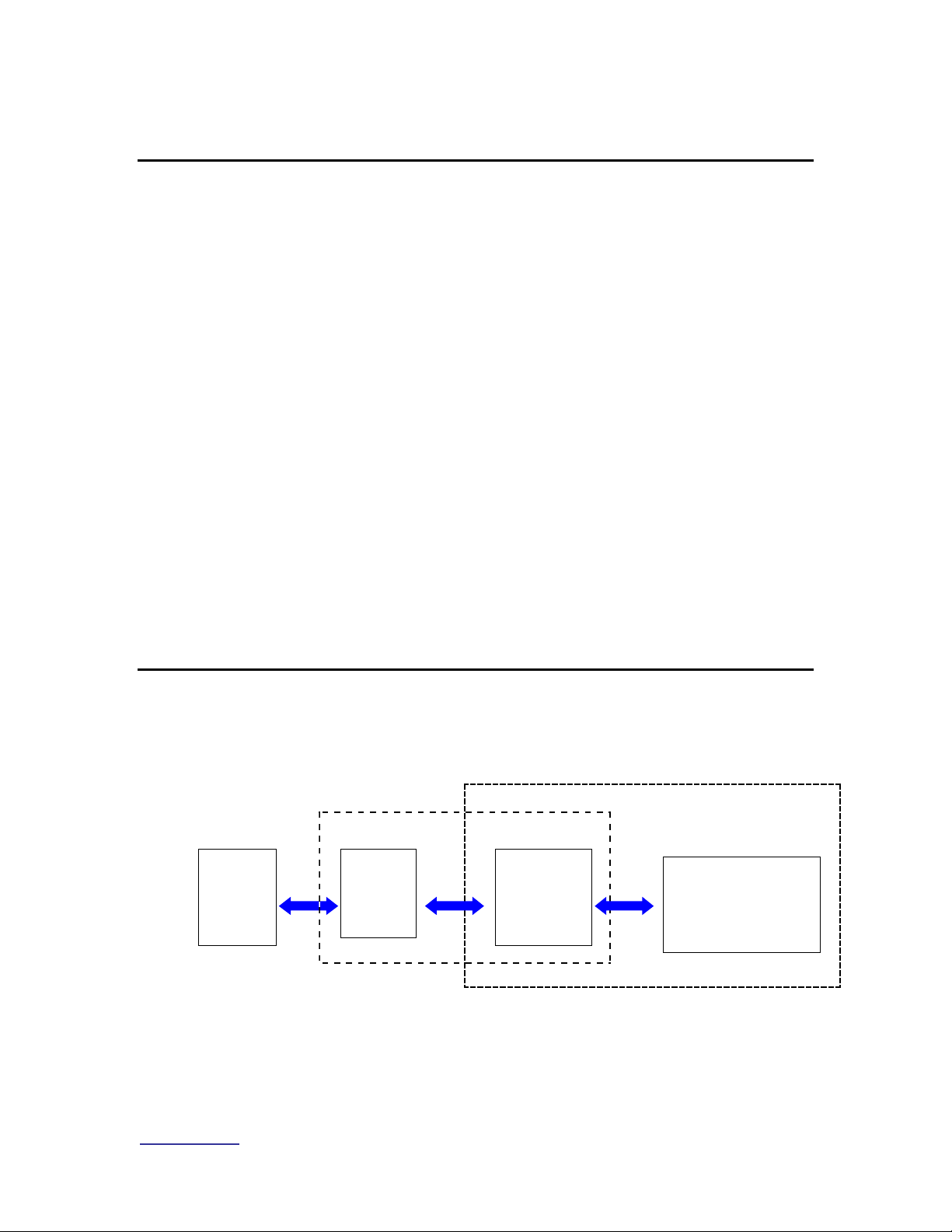
The system acts as an RF bridge between a network, typically the Internet or the
Public Switched Telephone Network (PSTN) (at the head end) and customer
equipment at the other end of the RF link.
It may be visualized as a three layer protocol stack. The highest layer may be
any one of the following: IP, E1/ T1 or PSTN.
All systems include the IP capability, which is required for network management.
The E1/T1 capability requires an additional plug-in card at the WMTS
Internet
or
PSTN
Wireless or HFC Network
Customer Premises
WMTS
Cable
Modem
(CM)
Customer
Equipment
Page 11

www.vyyo.com
System Configuration Introduction – p. 11
(Cable/Wireless Modem Termination System) end and an E1/T1 capable
cable/wireless modem at the downstream end.
The data from the IP, E1/T1, or PSTN layer are encapsulated as DOCSIS frames
which in turn are converted into RF signals and sent over the air or via an HFC
(Hybrid Coax Fibre) plant between the WMTS and modem.
Important Note: connectivity MUST be obtained at each
layer, beginning with the lowest (RF link) in order to
establish full communication.
Page 12
www.vyyo.com
System Configuration Introduction – p. 12
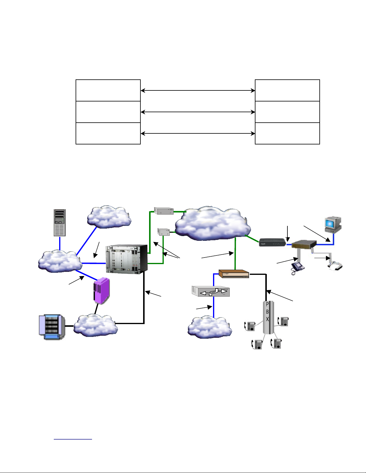
The following diagram illustrates this in the form of a three layer protocol
IP, E1/T1, POTS
RF Link
DOCSIS
WMTS
Modem
IP, E1/T1, POTS
RF Link
DOCSIS
Layer 3
Layer 2
Layer 1
RxTxV280 Modem
100BaseT
IP Network
MTA
PC
Line #2
Line #1
Phone
RJ-11
RJ-11
PSTN
H.323v2 or
MGCP, VOIP
Packet
Voice
E1/T1
V311 E1/T1 Modem
IP Router
Provisioning
Services
WMTS
Internet
Telephone
Switch
PBX
Intranet
RF Coax
RF Cloud or
Cable Plant
100BaseT
E1/T1
100BaseT
stack:
This illustration shows how a complete system is connected:
Connection Legend:
Blue = 100BaseT Ethernet
Green = RF Coaxial cable
Black = T1/E1
Grey = RJ-11
Page 13

www.vyyo.com
System Configuration Introduction – p. 13
There are different configuration requirements for each layer and different
software tools accomplish this task. The configuration of the RF link is typically
unique to each installation with the particular downstream and upstream
frequencies, modulations and bandwidths being the critical parameters that must
be set on the modem and WMTS.
Whereas there is no set standard for implementing an RF link, DOCSIS is a fully
specified protocol as are the upper layers (IP, E1/T1 or PSTN). The following
sections will describe the currently available system components (equipment)
then detail how to configure each of them in turn.
1.2 Equipment Capabilities
There are several different modems available, the simplest being the DOCSIS
modems with IP-only capability. All of the other modems use these as their
foundation.
The WMTS used at the head end is the other major component. There is only
one basic configuration, which is augmented with additional plug-in cards to
accommodate E1/T1 and PSTN capabilities.
NOTE: The term WMTS was originally conceived as
“eVyyoed” CMTS for use in a cable plant, hence the “X”.
This was followed by WMTS in which the “W” indicates a
“wireless” CMTS. For practical purposes these terms are
interchangeable and in some places the software uses
the term “WMTS” when referring to any one of these
systems.
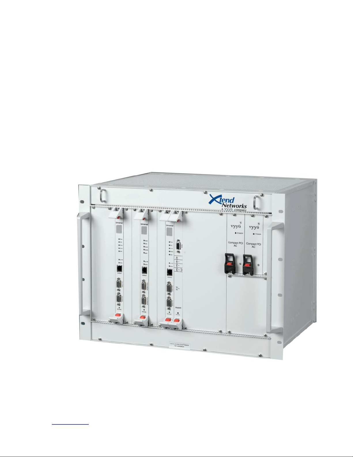
1.3 WMTS
The basic WMTS is a chassis with a power supply and a mid-plane PCI bus that
accommodates plug-in cards at the front and rear. Two redundant power supply
cards are provided at the right end of the front of the chassis.
The minimum required hardware configuration for an IP-only system consists of
one "HOST" card and three "Universal" cards. One Universal card acts as a
"Control and Forward" (C&F) card, one as the "Upstream" digital card and one as
the "Downstream" digital card. These latter two cards are attached to RF cards
in the rear slots.
E1/T1 capability may be added by replacing the Host card with a Master4 card,
and adding one or two E1/T1 interface cards in the rear slots to provide 12 or 24
E1/T1 ports, respectively. An DS3 version of the Master4 card which allows 28
T1 connections is also available. This card has two coax connectors (one for
receive and one for transmit) in place of the E1/T1 interface cards.
The HOST or Master4 card serves as the PCI bus arbiter and provides the
system clock and timing. When the WMTS boots, the Master4 card initializes,
then identifies the C&F card. The C&F card then directs the configuration and
downloading of relevant application software. The C&F card is connected
through a 100 BaseT Full Duplex connection to the switch or router and used to
transport data (including management packets) through the system.
Page 14
www.vyyo.com
System Configuration Introduction – p. 14
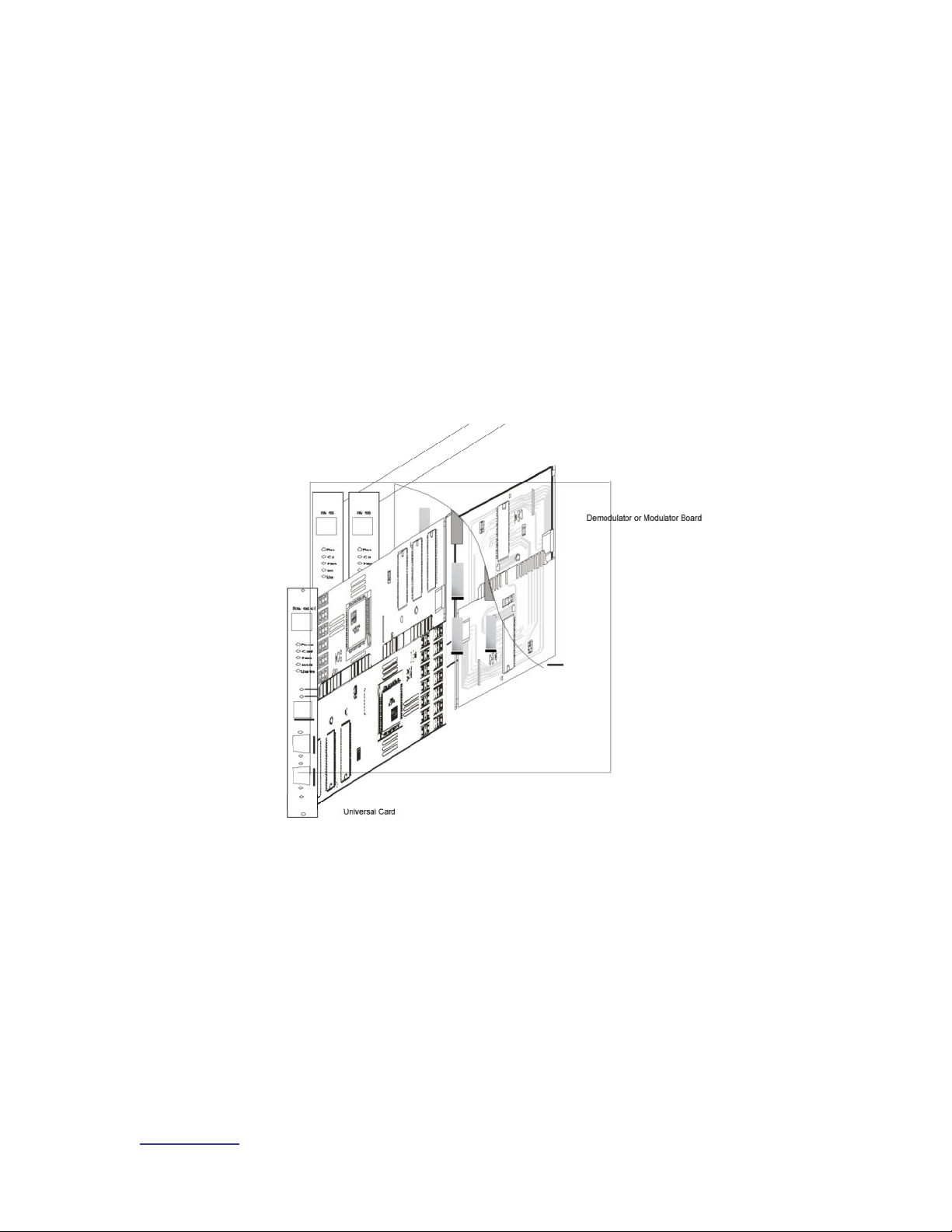
All Universal cards are the physically identical: the card attached to each of them
in the rear slots and the application downloaded during initial startup determine
the function of the card (Upstream, Downstream or Control & Forward).
In the rear slots, one Downstream and one Upstream RF interface card are
required. Each of these corresponds to its companion Universal card. The
“Quad” downstream card has four RF connectors and provides four downstream
channels. The “Hex” upstream card has six RF connectors and provides six
upstream channels.
Note: All Downstream cards have a fixed output
frequency of 44 MHz which must be converted up per the
local requirements.
Upstream cards may be configured to receive any
frequency from 5-65 MHz
Figure 1-1. The WMTS Chassis with (from left to right) Upstream card,
Downstream card, Control and Forward card, MASTER4 card, and Power
Supplies shown.
The WMTS is mounted in a standard 19” by 6U high rack-mounted chassis.
The chassis has a fan tray above the unit, bringing the total height required
Page 15
www.vyyo.com
System Configuration Introduction – p. 15
in the rack, to 8U. The eight bay chassis contains eight slots in the front, six
slots in the rear, and a mid-plane card in between, used to interface the
cards. Blank panels cover unused slots.
A standard 33 MHz, 32 bit Compaq PCI bus is used to transfer traffic and
data between the system cards. The power supplies, Master4 card and the
universal cards are inserted in the front slots of the chassis. The Quad
Downstream, Hex Upstream, and E1/T1 cards are inserted in the rear slots
of the chassis.
The ON/OFF power switch and the fuse are located in the rear of the power
supply.
Figure 1-2. Midplane Cutaway View of WMTS; Universal Card Shown in
Cutaway attached to an RF card.
Page 16
www.vyyo.com
System Configuration Introduction – p. 16
1.4 Modems
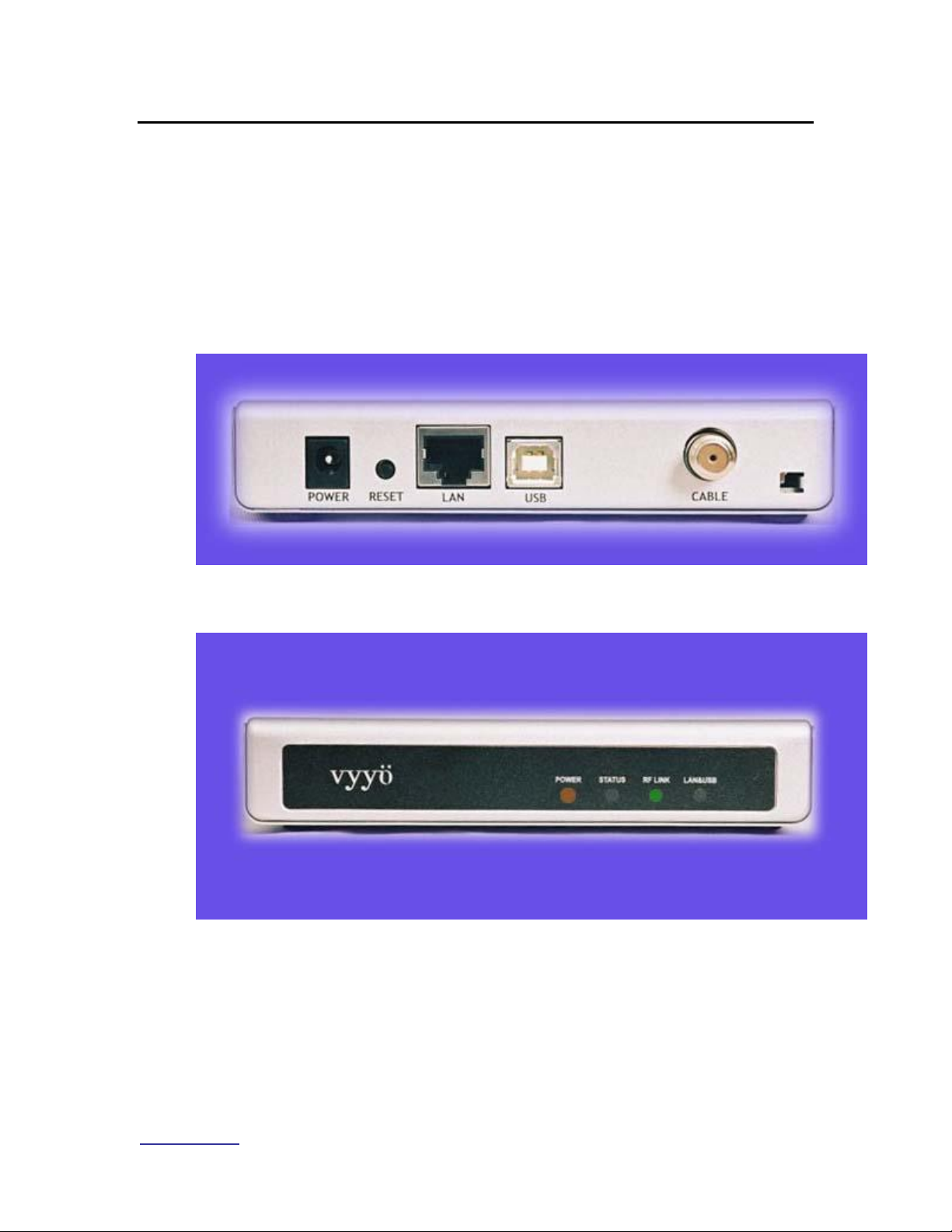
1.4.1 Modems with DOCSIS and IP only
The V280 is Vyyo’s “IP-only” modem. It uses an RJ45 connector (shown below)
on the rear panel to provide IP connection to the customer’s equipment. The
V280 supports up to 63 data users simultaneously and provides privacy,
authentication, service classification, prioritization, and traffic shaping.
The USB connector is not supported at this time. Check with Customer Support
for updates as they become available if you need this capability.
Figure 1-3. V280 Rear Panel
Figure 1-4: V280 Front panel
Hyperterm (a Windows terminal application which permits either a serial or direct
IP connection and is used in the following examples) or Telnet may be used to
connect the modem to a computer to configure parameters in the modem, such
as the downstream receive frequency. Any equivalent software utilities may be
used.
A basic WMTS unit (without E1/T1 capability) is all that is required at the head
end to complete an IP connection.
Page 17
www.vyyo.com
System Configuration Introduction – p. 17
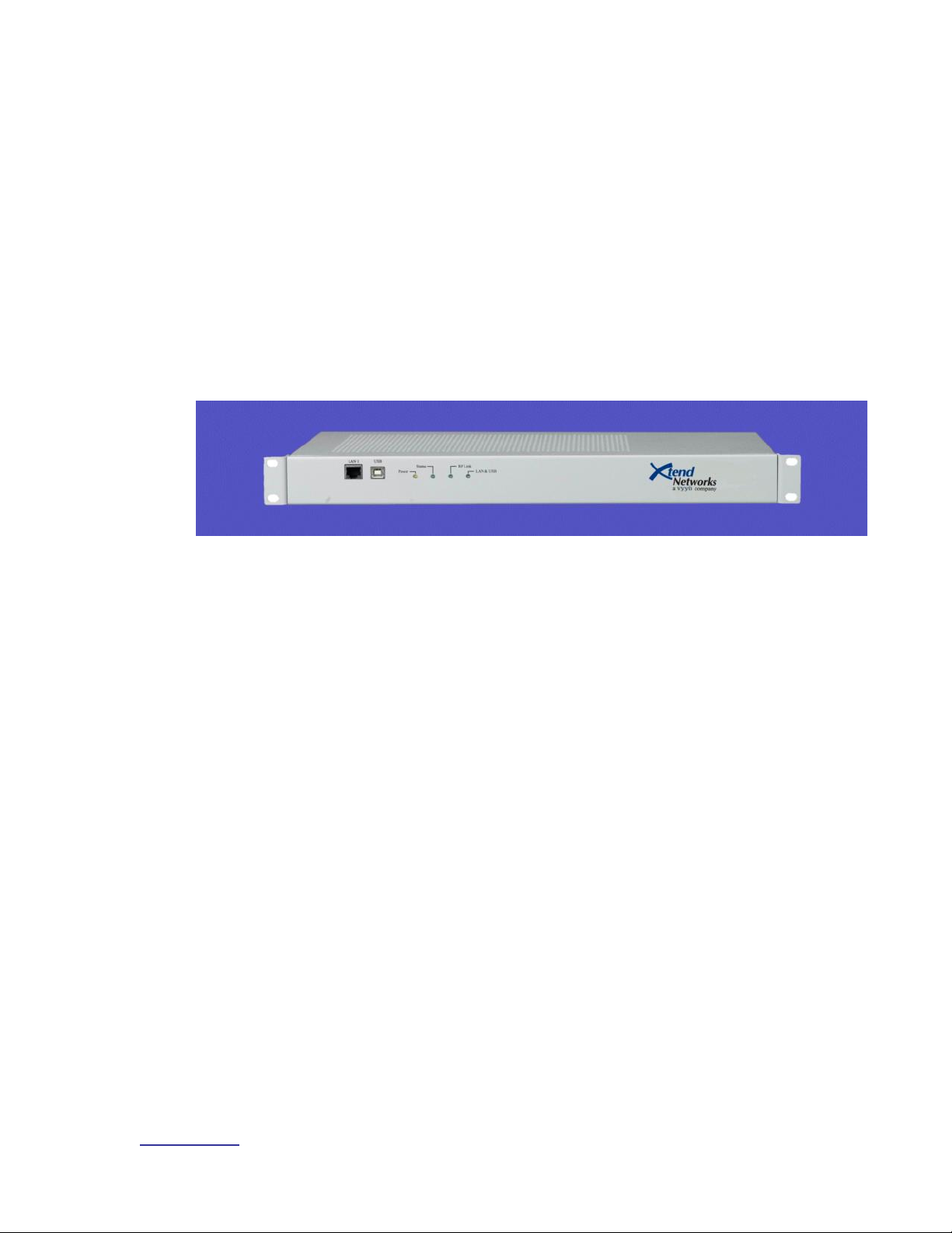
1.4.2 Modems with DOCSIS, IP and E1/T1
The V311 is a V280 modem (to provide the DOCSIS layer) with one E1/T1
interface (via an RJ45 connector on the front panel) added. In addition to IP
connectivity, it supports circuit switched E1/T1 applications. It has one 100
BASE-T port for IP data and one E1/T1 port which can support up to 32/24 time
slots.
The E1/T1 application supports framed or unframed E1/T1 services. In the case
of unframed configuration, all 32/24 time slots (including time slot 0) are delivered
over the air.
In the case of framed E1/T1 configuration, a full or fractional E1/T1 (any number
up to 31/23 time slots) can be delivered.
The V311 modem is shown in this image:
Figure 1-5: V311 Modem
Page 18
www.vyyo.com
System Configuration Introduction – p. 18
The V312 is identical to the V311 but has two E1/T1 interfaces instead of one.
The WMTS at the head end requires one or two E1/T1 interface cards (plugged
into the rear slots, with the second E1/T1 card attached to the first one as a
daughter board) to work with the V311 or V312. The E1/T1 connection will be
terminated at one of the ports on this (rear) E1/T1 interface card(s). In addition,
a separate software load is required.
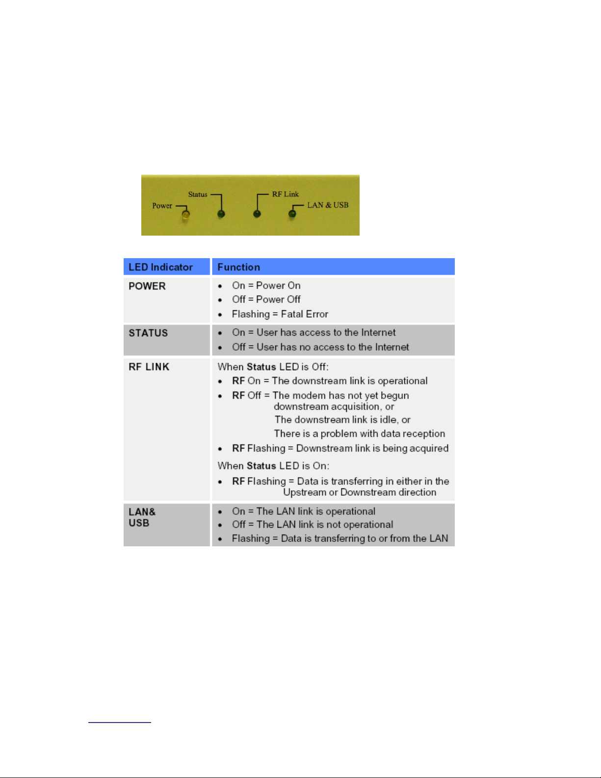
All modems have four LED indicators, described below.
Figure 1-6. LED Indicators
Table 1.1 LED Indicators, Functions, and Conditions
1.4.3 Modems with DOCSIS, IP and PSTN
The V313 is a V280 (for the DOCSIS layer) with a PSTN interface added: this
physical interface (provided with the V313) comprises four RJ45 connectors,
each of which connects to a special cable terminated in four RJ11 connectors,
allowing a total of sixteen PSTN devices to be connected.
The WMTS at the head end requires an E1/T1 card and a V5.2 AN stack
(additional software available from Vyyo) to work with this unit. If you plan to
deploy the V313 please contact your Vyyo representative.
Page 19
www.vyyo.com
System Configuration Introduction – p. 19
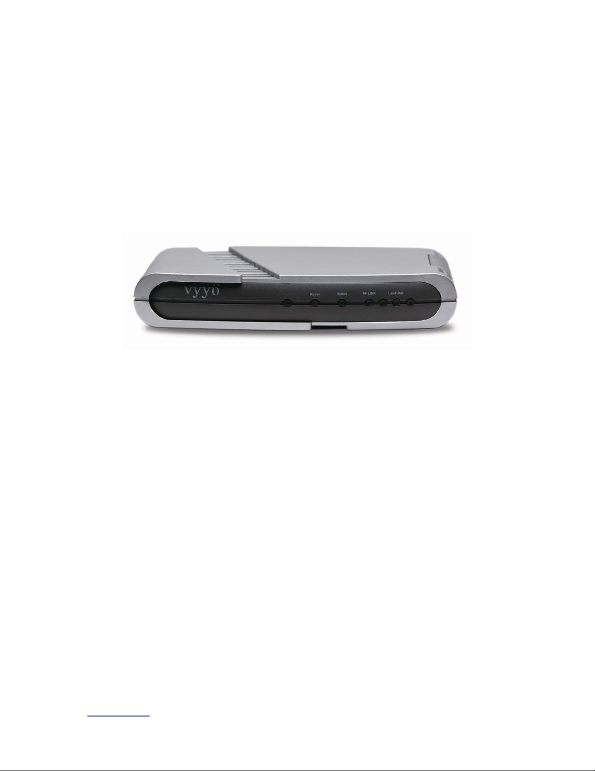
1.4.4 Modems with DOCSIS and IP Only With Built in UHF Radio
The V284 modem is a basic V280 modem integrated with a built-in UHF radio
that provides an upstream RF output in the 710-716 MHz range. Internally the
V284 has a factory set intermediate frequency of 44MHz which is converted up to
yield an appropriate upstream frequency (This is preset at the factory for 700MHz
in the United States).
The downstream frequency ranges from 740-746MHz. Note that the RF setup of
this radio requires appropriate preplanning owing to the complexity introduced by
the internal UHF radio. Please reference the UHF System Installation Guide
and/or your local system engineer.
Figure 1-7: V284 Modem
Page 20

www.vyyo.com
System Configuration Introduction – p. 20
1.5 Modem Capabilities Matrix
Modem
Model
Modem
Hardware
Connectivity
Additional
WMTS
Cards
required
Description
V280
V280
IP
none
The basic DOCSIS modem
V311
V280
plus
E1/T1
card
IP, E1/T1
E1/T1
interface
card and
Master4 card
A V280 modem with one
E1/T1 interface (one RJ48
connector on the front which
can handle one E1 or T1
line)
V312
V280
plus
E1/T1
card
IP, E1/T1
E1/T1
interface
card and
Master4 card
A V280 modem with two
E1/T1 interfaces (two RJ48
connectors on the front
which can handle one E1 or
T1 line each)
V313
V280
plus
internal
PSTN
card
IP, PSTN
E1/T1
interface
card and
Master4
card with
additional
V5.2 AN
stack
A V280 modem with a builtin PSTN interface (four
RJ45 connectors each of
which attaches to four RJ11
POTS connectors)
V284
V280
plus
internal
UHF
radio
IP
none
A V280 modem with an
internal UHF radio for
communication in the
700MHz range – special RF
configuration is necessary.
Please see the UHF System
Installation Guide.
Page 21

www.vyyo.com
Configuration Overview – p. 21
Chapter 2. Configuration Overview
This section of the System Configuration Guide features a short overview of each
component/layer of the System including the WMTS and the modems. The last
section is a summary presented as a matrix that shows the relationships between
the various tools and files. The components and layers are described below.
• Network Servers
o DHCP Server
o TFTP Server
o Time of Day (ToD) Server
• RF Link Layer
• DOCSIS Layer
2.1 Network Servers
The following servers are required for successful completion of modem
initialization. They will be accessed by the modem and the WMTS at specific
points during the registration and installation process.
2.1.1 DHCP Server
This server binds the modem’s MAC address to both its Network IP address
and its configuration (or “boot”) file, which contains several important system
specific parameters required for the modem to communicate with the WMTS.
Viewing this information can help in troubleshooting any problems which may
occur.
2.1.2 TFTP Server
This server downloads the selected configuration file to the modem during
the registration process when the modem requests it. It also downloads files
and configuration information to the WMTS. This information is used for
initial (first time) startup and for troubleshooting.
2.1.3 Time-of-Day (TOD) Server
This server provides the Time of Day to the modems and the WMTS. It
allows the WMTS and the modem to coordinate their timing.
2.2 RF Link Layer
This network layer is unique for each installation and depends on the
available frequencies, the frequency plan, the specific hardware used for the
installation, and other factors.
Page 22

www.vyyo.com
Configuration Overview – p. 22
Your System Engineer must develop a detailed system plan that accounts
for each of these variables. This plan must include the assignments of
downstream frequencies, modulations (and other RF parameters) and
upstream channel IDs assigned to the various modems deployed in the
network. If the modems are to be used with E1/ T1 connections, all related
parameters, especially QoS (Quality of Service, also referred to as Class of
Service) parameters, also need to be defined (these are discussed later in
this document.)
NOTE: The methods to define these factors are unique
to each customer and are outside the scope of this
document. They are part of the site preparation and preplanning, including any “overbooking” scheme that may
be desired. Please consult your Vyyo representative or
system integrator for assistance.
The Downstream and Upstream frequencies, modulations and bandwidths
MUST be pre-determined in order to proceed with the configuration of the
WMTS and the modems. Each modem must be assigned to a specific
WMTS Upstream Channel (the upstream channel is referenced by its
Channel ID which identifies the physical port.) The Upstream channel must
be configured for a specific frequency, modulation and bandwidth or symbol
rate.
NOTE: The WMTS must be configured to use the correct
Upstream and Downstream parameters. This is done
using the Vyyo Configuration tool.
It also recommended that each modem is assigned to a particular
Downstream channel (or set of channels.) The modem can use Downstream
channel discovery, however; it is typically not used since it takes much
longer to discover the correct frequencies.
Using pre-determined frequencies also allows greater control over the RF
frequency assignments and can distribute network bandwidth more
efficiently. A range of frequencies can be defined in the modem
configuration file to cover all customer assigned bands and to minimize
future re-configuration.
NOTE: The modem’s Downstream ferequency is preset
at the factory but may be changed on the modem by
using a direct Telnet connection. See Section 5.4 Setting
the Modem’s Downstream Frequency for details.
2.3 DOCSIS Layer
The most important items that must match are:
The WMTS Downstream Frequency and the modem Downstream Frequency
The WMTS Upstream Channel ID and the modem Upstream Channel ID (their
associated parameters must also match.)
Page 23

www.vyyo.com
Configuration Overview – p. 23
First, the modem searches for a signal at its preprogrammed Downstream
Frequency. Once having locked to that downstream channel, the modem
receives upstream channel descriptors (UCDs) from the WMTS that describe the
available upstream channels.
NOTE: The WMTS must be configured to construct the
UCDs so that they correspond to the site preplan. Use
the Vyyo Configuration Tool to accomplish this if any
changes are required.
The modem then enters a protocol exchange that requires data be transmitted
from the modem to the WMTS via an Upstream Channel using its associated
Channel ID (designating the physical interface on the RF Interface card), and the
correct frequency, modulation and bandwidth or symbol rate.
NOTE: A modem configuration file which respecifies
these parameters is downloaded to the modem after
“ranging” (described below) is complete . This file is also
referred to as the modem “boot” file. All further
communication done by the modem uses the parameters
specified in this file. The modem configuration file is
modified using the CMconfigFileEditor tool.
This protocol exchange allows the modem to ‘range’ (adjust its timing and power
level so that it can work successfully with all of the other modems on line at this
time.). After the ranging is finished, the modem has successfully established
physical layer and Link or MAC layer connectivity with the WMTS. The WMTS is
now capable of sending MAC layer packets such as DHCP and ARP requests
required to complete the registration process.
2.4 IP Layer
Your System Engineer must devise a Network IP Plan. This is required in order
to assign IP addresses to the WMTS and all the modems on the network. It must
include the IP address of all the servers as well as the network mask and other
network parameters.
After connectivity is established at the DOCSIS layer (discussed in Section 2.3
DOCSIS Layer ), the modem is assigned to an IP address by using DHCP
(Dynamic Host Control Protocol.) If using the ipLease tool as the DHCP Server,
this is usually a static IP address defined in the DHCP setup file (CM.SRC.) This
file binds the modem's MAC address to a particular fixed IP address. If using
Windows 2000 Server Edition this binding is accomplished using its DHCP
Administrative Tool, which may be installed at the user’s option using the “netsh”
command (follow the instructions provided with your server).
The DHCP server grants the “lease” on the IP address to the modem (i.e., tells
the modem which IP address to use). The granted IP address is for SNMP
connectivity within the Vyyo system; it is not offered as a public IPaddress to
Vyyo equipment. However, if desired this can be done using the customer PC or
Router as the modem will behave as Layer 2 bridge device.
Page 24

www.vyyo.com
Configuration Overview – p. 24
For the ipLease DHCP Server tool, the CM.SRC file is an ASCII text file that may
be edited using any text editor (such as Notepad). This document describes the
configuration process using the ipLease tool. The changes are similar for other
DHCP servers. Note that if another operating system, such as the Windows
200x Server, is used a DHCP server is often included. Check with your Vyyo
representative to make sure the DHCP server is compatible.
NOTE: Before the modem can acquire an IP address, the
WMTS must be configured with its own IP address This
procedure is described later in this document in the
section entitled Setting the WMTS IP Address. The
WMTS IP address is specified in a different configuration
file (regtree.rtr) which may be edited using the
XmtsConfigurationFileEditor tool.
After the modem successfully receives its IP address it contacts the TOD server
to establish the time of day. Next, it contacts the TFTP server to download the
modem configuration file, which specifies the final DOCSIS parameters for the
modem. This file is also referred to as the modem “boot” file. All further
communication done by the modem uses the parameters specified in this file.
This file may cause the modem to change frequencies or reboot in order to reset
some of its configuration parameters. The modem will acquire this file every time
it is reset or restarted. Configuration changes to the modem configuration file
(profile) will be done from the Operation center with out the need to visit the
modem remote location for any setup change; These changes may include
encryption, QoS., IP filters, downstream channel parameters. etc….
NOTE: the modem configuration file is modified using the
CMconfigFileEditor tool..
During the final phase of the DOCIS registration process, the modem sends a
registration message to the WMTS confirming that the configuration file was
received. The WMTS retrieves a copy of the configuration file from the
configuration file server TFTP root repository directory. The WMTS then
compares the file from the server with the data from the modem to ensure that
the modem will only use services for which it was authorized. The modem is then
finally allowed to transmit real user data into the network, but only after the
modem’s configuration file values are crosschecked by the WMTS.
At this point, a data only modem will be successfully connected to the system.
2.5 E1/T1 Layer
After IP connectivity is established, E1 or T1 connectivity may be established.
Note that in addition to installing an E1/T1 card into the WMTS chassis, E1 and
T1 each require that different firmware be loaded into both the WMTS and the
modem.
The E1/T1 configuration will require appropriate changes to the modem
configuration file in addition to setting those configuration parameters used for a
Page 25

www.vyyo.com
Configuration Overview – p. 25
standard IP-only modem. The same modem configuration file may be used for
several modems provided the Downstream frequencies and the Upstream
Channel ID are the same (i.e., same “profiles”).
The WMTS E1/T1 configuration needs to be modifed appropriately for every
E1/T1 modem installed on the network. This is done using the Java™-based
Vyyo Configuration tool. This tool configures the E1/T1 port on the modem to be
connected (“bound’) to the correct E1/T1 port on the E1/T1 card plugged into the
WMTS.
After this tool is used to bind the E1/T1 ports together and the standard modem
provisioning is done, the installation is complete and the E1/T1 services in the
modem are ready to be activated.
Page 26

www.vyyo.com
Configuration Overview – p. 26
2.6 Configuration Tools and Files Matrix
Tool
Configured
File or Device
Description
CMconfigurationFileEditor
Modem
Configuration
file (e.g.,
“MIC_xxx.cfg”,
where xxx is
some unique
number.)
This file downloads to a modem
during the registration process.
It contains all the parameters
required for the modem’s
operation in the DOCSIS
network: upstream and
downstream frequencies, QoS,
etc. It is also call the modem
“boot” file.
XmtsConfigurationFileEditor
(any standard ASCII text file
editor may also be used to
edit the text version of the
file)
Regtree.txt
Regtree.rtr
(downloadable
version of the
text file)
Regtree.txt contains the
permanent IP address of the
WMTS. This tool is a
convenient way to edit the more
common items in the file.
However, when editing the
WMTS IP address you must
use a standard text editor. The
Regtree file may be saved in
either text or downloadable
format using this tool.
SETIP.BAT
Regtree.txt
This batch file is used to
convert the text version of the
Regtree file to the
downloadable format
(Regtree.rtr). It calls
RTR2TXT.EXE and
RECFMT.EXE to do the
conversion.
RTR2TXT.EXE
Regtree.rtr
This tool is used to convert the
Regtree.rtr file to a standard
text file (Regtree.txt)
XmtsConfig
WMTS
Used to assign a temporary IP
address to the WMTS and to
download files to the WMTS.
Specifically it must be used to
download the compiled version
of the Regtree.txt file to the
WMTS. This is primarily used
during initial setup.
Page 27

www.vyyo.com
Configuration Overview – p. 27
Vyyo Configuration Tool
WMTS MIB
database
This is a standalone JAVA
based tool that can be
accessed from the NMS. It is
used to modify and configure
the WMTS operating
parameters.
NMS (Castlerock)
WMTS or
Modem MIB
values
(Typically for
viewing only.)
A general purpose Network
Management System for
operating the network; also
used to launch the Vyyo
Configuration tool.
Any ASCII text editor, e.g.,
Notepad
CM.SRC
Used with ipLease (the DHCP
server) to bind a modem’s MAC
address to its network IP
address and its modem
configuration file (downloaded
during modem initialization) as
well as other network
parameters needed to
configure the modem.
DHCPGen
CM.SRC
Converts the file to a format
that ipLease can use
DHCP Server
modem
Sends the modem its network
IP address and the name of its
modem configuration file as
well as other information
needed to setup IP
connectivity.
TOD Server
modem
Used to set the time of day in
the modem and the WMTS
TFTP Server
modem and
WMTS
Used to send the modem
configuration or “boot” file to the
modem during initialization;
also used to load the WMTS
application and configuration
files
Telnet
Modem
Used to set the downstream
frequency that the modem will
scan to listen to the WMTS.
Also used to set the RF offset if
required.
Page 28

www.vyyo.com
The Modem Initialization Process – p. 28
Chapter 3. The Modem Initialization
Process
To understand the configuration process, it is useful to understand the
detailed steps the modem goes through during its initialization.
When the modem is first powered up, it must go through a fixed sequence of
steps before it can exchange data with the network. To be successful, this
requires the modem and the WMTS to be configured with various
parameters.
These parameters should be defined in a Network RF Plan and a Network IP
plan set up by your System Engineer. The three Network Servers (TOD,
DHCP, and TFTP) must be installed and operational. The WMTS must be
configured with the correct software and an IP address.
The modem’s RF parameters must also be correctly configured with the
proper software and its RF parameters must be set correctly. When all of
this is done, the modem is ready to initialize itself when placed at the
customer’s premise.
Finally, after initialization, the modem’s E1/T1 port must be “bound” (configured
to connect) to the correct E1/T1 port on the WMTS. This step may be done last
or pre-configured before the modem is at the customer’s premise.
The following sections provide an overview of the modem initialization process.
3.1 Modem Initialization Sequence
All modems proceed through the following sequence of steps, each of which
is described in more detail below. The completion of these steps establishes
connectivity at the DOCSIS and IP layers. Connectivity for additional layers,
e.g., E1/T1, may then be established for the V311 and V312 modems. The
steps are:
• Power-On Self Test
• Downstream Synchronization
• Obtain Upstream Parameters
• Ranging
• Establish IP Connectivity
• Establish Time of Day
• Transfer Operational Parameters
• Registration
• Baseline Privacy Initialization
3.1.1 Power-On Self Test
The modem performs a self-check to ensure that its hardware is working
properly.
Page 29

www.vyyo.com
The Modem Initialization Process – p. 29
3.1.2 Downstream Synchronization
The modem listens for downstream transmissions from the WMTS (which
are broadcast at frequent intervals for exactly this purpose) according to its
pre-configured or default frequency plan. This may be a single fixed
frequency or a sequence of frequencies, depending on the Network RF Plan
and/or the internal programming of the modem.
If the modem is programmed for a single fixed downstream frequency and
fails to receive an WMTS downstream transmission after three attempts it
switches to its additional backup frequencies. See Setting the Modem’s
Downstream Frequency for a description of how to set these parameters.
Synchronization is obtained when the modem locks onto the WMTS
downstream signal and is able to recognize downstream SYNC messages
which are periodically broadcast: these are crucial to calculating the time
slots available for upstream transmission.
3.1.3 Obtaining Upstream Parameters
The modem must now wait to collect all the Upstream Channel Descriptors
(UCDs) for all upstream channels that are connected to the current
downstream channel.
3.1.4 Ranging
The modem then sends a “ranging request” message on one or more of the
Upstream frequencies, corresponding to a UCD, at different power levels in
an attempt to establish communication with the WMTS. Eventually the
WMTS decodes a ranging request from the modem and sends a ranging
response.
Ranging is now complete. Whenever the modem needs to send MAC layer
data for IP to the WMTS it sends a “request” to the WMTS. The WMTS
schedules a time slot for the modem and sends a “grant” message back to
the modem that contains all the necessary information telling the modem
when it can transmit data. A similar method is used to send E1 or T1 data
except that the request sets up periodic time slots that the modem uses to
transmit data.
3.1.5 Establish IP Connectivity
The modem uses the “request-grant” (“best effort”) mechanism to send a
standard DHCP request to the Network DHCP server. The server will
recognize the modem via its MAC (Ethernet) address and assign it a
temporary IP address. This response also contains the default gateway and
the IP subnet mask. The IP addresses of the TFTP and ToD servers, and
the name of the modem configuration file are also included. The response
also includes the local time offset from Universal Coordinated Time (UTC).
Once the modem receives this response it sets its IP address to the
designated value and uses the default gateway to talk to devices using its IP
stack.
Page 30

www.vyyo.com
The Modem Initialization Process – p. 30
3.1.6 Establish Time of Day
The modem uses the ToD server address(es) just received to send a Time of
Day request to the ToD server(s). This is combined with the time offset
received in the DHCP response to calculate the current local time. The Time
of Day is used by both the modem and the WMTS to timestamp logged
events (accessible via the Network Management System).
3.1.7 Transfer Operational Parameters
The modem then requests the TFTP server to send the configuration ( or
“boot”) file named in step (5) above during the establishment of IP
connectivity. If the boot file specifies a different upstream channel and/or
downstream frequency, the modem must repeat its initial ranging using this
new upstream channel and/or downstream frequency.
3.1.8 Registration
In order to forward traffic into the network the modem must be “registered”
with the WMTS. To register, the modem sends the WMTS its class of
service (also called QoS for Quality of Service) and any other operational
parameters it received in the configuration file as part of a Registration
Request. As part of the registration process the modem calculates Message
Integrity Check (MIC) values using the parameters specified in its
configuration file. This must match the values given for those parameters in
the configuration file itself.
3.1.9 Baseline Privacy Initialization (BPI)
If the modem is enabled to run BPI then encryption and decryption keys are
established. All further data to or from the modem is now encrypted. The
keys have a lifetime and are automatically reset to new values after a
specified period which may be set by the operator using the NMS.
NOTE: BPI is required in order to support E1/T1
Page 31

www.vyyo.com
Overview of the WMTS and Modem Configuration – p.
31
Chapter 4. Overview of the WMTS
and Modem Configuration
This section provides an overview of the steps and tools necessary to configure
both sides of the communications link (WMTS and modem) required to add a
data modem or the data portion of a new E1/T1 modem to the network. Several
different tools and files are used as described below.
1. Make sure that the three required servers are installed and operational:
DHCP, ToD and TFTP. For details see Chapter 8, Installing Vyyo
Servers for WMTS Operation. The failure of the modem to establish
communication with any of these three servers will prevent the modem
from completing the registration process.
2. Review the Network IP Plan and use it to assign an IP address to the
WMTS, then make it permanent by following the procedure in the section
Setting the WMTS IP Address.
3. Verify that the right software version is loaded into the WMTS as
described in Appendix B. See the “readme” notes in the distribution
software for the version number.
4. Review the RF plan for the network and configure the WMTS upstream
and downstream channels accordingly using the procedures in Setting
the Upstream Channel. It may not be necessary to configure new
upstream and downstream channels when adding a modem; but if
required, the Vyyo Configuration tool can be used to modify these
parameters.
5. Review the RF Plan to find out which downstream frequency(ies) and
upstream channel ID(s) the modem will use to communicate with the
WMTS. Use the CMConfiguration Editor (CMConfigFileEditor.exe) to
edit the modem configuration file that will be downloaded to the modem
during the modem initialization sequence to reflect these choices and
other needed parameters (e.g., QoS or Class of Service, Max Number of
CPE, BPI Enable/Disable – required for E1/T1, etc.). If you know in
advance that this modem will be used for an E1/T1 connection then
additional edits may be made at this time as described in Chapter 6,
Configuring a T1 Connection.
NOTE: One modem configuration file may be used for
several modems if the same upstream channel ID and
downstream channel are used by all the modems (i.e.,
same “profile”); thus, this step may not be required every
time a new modem is added to the system.
Page 32

www.vyyo.com
Overview of the WMTS and Modem Configuration – p.
32
6. .
NOTE 1: Five T1s per 3.2MHz upstream channel using
16QAM modulation is the hard limit for the current
system. Attempting to configure more T1s on an
upstream channel than it can support will cause the
modem initialization to fail. Consult your system engineer
for advice on the maximum number of modems per
upstream channel ID.
7. Use the appropriate DHCP tool for your system to bind the modem’s
MAC address to its IP address and modem configuration file. If ipLease
is used, edit and compile the CM.SRC file as needed. If Windows 200x
Server Edition is used then set these values using the graphical user
interface. These procedures are described in section 5.2.2, Windows
200x Server Edition: Modifying the DHCP Options
NOTE: this step is ALWAYS required when adding a
modem
8. Use the modem’s Telnet server interface to set the modem to a
permanent downstream frequency as described in Setting the Modem’s
Downstream Frequency. Having a permanent (fixed) downstream
frequency (or set of frequencies) expedites the modem initialization
process since the modem does not have to scan multiple downstream
frequencies to find one being transmitted from the WMTS. This does,
however, require some pre-planning of the network to pre-allocate
different downstream frequencies to specific modems. Ask your System
Engineer for details.
NOTE: this step is ALWAYS required when adding a
modem with a fixed permanent downstream frequency
9. If a T1 connection is being setup then use the procedures in Configuring
a T1 Connection. Configure the WMTS upstream channel ID for E1/T1
operation and bind the WMTS upstream channel ID to the modem E1/T1
interface and to bind the modem’s E1/T1 interface to a particular port on
the E1/T1 card plugged into the WMTS (use the Vyyo Configuration tool
for this procedure.)
NOTE: the Vyyo Configuration tool binding operation will
ALWAYS be required when adding a T1 modem. This
step can be done after the modem is installed at the
customer’s site.
10. Install the modem at the customer site and connect it to the RF
equipment, provide power to the modem and turn it on.
NOTE: This step is ALWAYS required when adding a
modem
Page 33

www.vyyo.com
Overview of the WMTS and Modem Configuration – p.
33
11. If the modem is already on and its modem configuration file has been
changed (to bind the E1/T1 ports), then the modem must be rebooted;
although this happens automatically when the DHCP lease expires, it is
more efficient to simply power cycle the modem (unplug and replug the
power connector or switch the modem OFF then ON) to restart the
modem initialization sequence.
12. If desired, connect the modem’s internal Telnet server to a local
computer system to observe the process on site and verify that the
modem is working correctly.
The POWER and STATUS LEDs should be lit and the LAN & USB, and
RF Link LEDs should be flashing (one at a time) with activity:
If the Power, Status, RF Link, and LAN/USB LEDs are lit, then the modem
has been successfully installed. If one or all of the lights remains unlit, see
Chapter 9, Maintenance and Troubleshooting
Page 34

www.vyyo.com
Adding a Modem to the WMTS – p. 34
Chapter 5. Adding a Modem to the
WMTS
NOTE: These instructions are required for all modems.
If you are adding a T1 modem then you must also
perform the step in Chapter 6, Configuring a T1
Connection to finish the installation.
Use the instructions in this chapter to setup a data modem or the data portion of
an E1/T1 modem and configure the WMTS to communicate with it over IP.
This chapter covers the following topics:
1. Section 5.1 Editing the Modem Configuration File describes the steps
necessary to setup the modem configuration file.
2. Section 5.2 DHCP Settings for the Modem explains how to set (bind) the
modem’s IP address and configuration file using either ipLease or the
Windows 200x Server Edition DHCP Server. explains how to set (bind)
the modem’s IP address and configuration file using either ipLease or
the Windows 200x Server Edition DHCP Server.
Page 35

System Configuration Guide
www.vyyo.com
Adding a Modem to the WMTS – p. 35
3. DHCP Settings for the ModemSection 5.3 Configuring the WMTS
describes how to configure the WMTS upstream, downstream and QoS
parameters. This is done using the Vyyo Configuration Tool. Instructions
for performing these changes are shown in Configuring the WMTS.
4. Section 5.4 Setting the Modem’s Downstream Frequency describes how
to set the modem downstream initial receive frequency via the modem’s
internal Telnet server.
5. Section 5.5 Verifying the Modem Downstream and Upstream Status
describes how to use the modem’s internal Telnet server to view the
modem’s downstream and upstream status (current values) and verify
correct operation.
5.1 Editing the Modem Configuration File
You will need to edit the modem configuration file to set the WMTS downstream
frequency, upstream channel ID, concatenation and fragmentation capabilities, and
QoS. This file will be downloaded to the modem during its initialization sequence.
NOTE: A separate modem configuration file is required
for each set of upstream and downstream channels. Any
modem may use any configuration file and the same file
may be used by many modems; typically only five T1
modems are assigned to a single 3.2MHz upstream
channel.
5.1.1 Setting the Upstream Channel
Open the CMConfigFileEditor to edit the modem configuration file to set the
Downstream Frequency and Upstream Channel ID.
Note: If using ipLease, the modem configuration file is
bound to the modem’s MAC address in the CM.SRC file.
If using Windows 200x Server Edition bring up the DHCP
Administrative Tool to find the configuration file to the
mode:
Programs->Administrative Tools->DHCP
For more detailed information, see section 5.2.2,
Windows 200x Server Edition: Modifying the DHCP
Options
From the main screen shown below select “General Parameters” and then
choose “Upstream Channel ID”.
Page 36

System Configuration Guide
www.vyyo.com
Adding a Modem to the WMTS – p. 36
Right-click on “Upstream Channel ID” and select “MODIFY” to display the popup
window in which you may set the value of the Upstream Channel ID.
Note: The detailed parameters for each upstream
channel must be set in accordance (see Setting the
Upstream Channel)with the overall Network RF Plan –
contact your system engineer for assistance. The
Channel ID is the identifier for the physical RF port on the
RF cards plugged into the rear of the WMTS. The ports
are numbered as follows:
Channel ID = card slot number + port number
Where the card slot number is zero for the leftmost
upstream card (as viewed from the front of the WMTS)
and increases by the ifIndex of the card times eight for
each additional card. The if index of the card can be
found in the ifTable. Please contact Vyyo for the exact
details of this configuration. Typically, the ifIndex
increases from left to right by 1 for each card, from 0 to n,
where n is the rightmost card. The ports are numbered
from bottom to top on each card starting with one. Thus,
the first card has ports numbered from 1 to 6 (since the
Hex upstream card only has six ports even though a
maximum of 8 are allowed) and the second card has its
ports numbered from 9 to 14, etc. Contact Vyyo for
Details.
NOTE 2: See Setting the Upstream Channel to set the
receive frequency of an upstream channel.
Page 37

System Configuration Guide
www.vyyo.com
Adding a Modem to the WMTS – p. 37
Figure 5-1: Setting Upstream Channel ID
Page 38

System Configuration Guide
www.vyyo.com
Adding a Modem to the WMTS – p. 38
5.1.2 Setting the Downstream Frequency
In the following example, the Downstream Frequency is changed to 743 MHz.
1. From the main screen shown below select “General Parameters” and
then choose “Downstream Frequency”.
6. Right-click on “Downstream Frequency” and select “MODIFY” to display
the popup window in which you may set the value of the downstream
frequency in Hertz (note the six zeroes).
NOTE: This value will be specified by your system
engineer.
Figure 5-2 Setting Downstream Frequency
Page 39

System Configuration Guide
www.vyyo.com
Adding a Modem to the WMTS – p. 39
5.1.3 Setting Concatenation and Fragmentation Capabilities
1. Select “Modem Capabilities” and enable “Concatenation” and
“Fragmentation” by setting them to “1” (select each one then right-click to
view the “Set Value” dialog box, enter the value “1” then click “OK”).
NOTE: These should always be used unless specified
otherwise by your system engineer.
Figure 5-3. Setting the Concatenation Value
Figure 5-4. Setting the Fragmentation Value
Page 40

System Configuration Guide
www.vyyo.com
Adding a Modem to the WMTS – p. 40
5.1.4 Setting Upstream QoS (Class of Service) for IP Data
1. Select “Class of Service Parameters”
2. Right-click on “Maximum Upstream Rate” to display a selection of QoS
profiles.
3. Choose the profile that is appropriate for the installation being done.
Your system engineer can provide assistance based on the Network RF
& IP Plan.
4. Select a profile in the left side of the popup window to display its
corresponding parameters on the right side.
Figure 5-5. Setting Upstream QoS
Page 41
System Configuration Guide
www.vyyo.com
Adding a Modem to the WMTS – p. 41
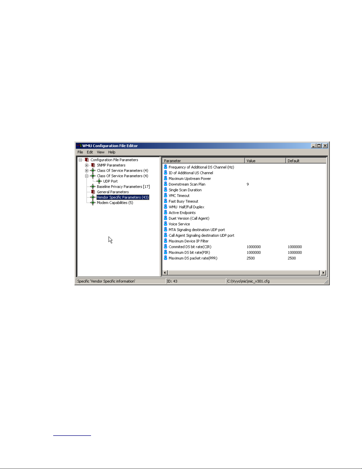
5.1.5 Setting Additional Downstream and Upstream Channels
Use the “Vendor Specific Parameters” option to set additional downstream
frequencies and upstream channels. Your system engineer should tell you if this
is necessary. First enter the Frequency of the Additional Downstream Channel in
Hertz and then enter the associated upstream channel ID (ID of additional
Upstream channels). To add more downstream and upstream frequencies right
click on the “Vendor Specific Parameters” option and select “Duplicate” to bring
up another screen and enter the desired values.
A Downstream Scan Plan value of ‘9’ indicates that the downstream channel is
set to a permanent fixed frequency (the advantage is that the modem initializes
faster and doesn’t interfere unnecessarily with other traffic on the network).
Figure 5-6: Using Vendor Specific Parameters to set additional DS/US pairs
Page 42

System Configuration Guide
www.vyyo.com
Adding a Modem to the WMTS – p. 42
5.1.6 Setting the Maximum Number of CPEs
It is advisable to set the maximum number of CPEs at this time by selecting and entering
the desired value on the following screen:
Figure 5-7: Setting the maximum number of CPEs
Page 43

System Configuration Guide
www.vyyo.com
Adding a Modem to the WMTS – p. 43
5.2 DHCP Settings for the Modem
The DHCP Server provides the IP address for the modem and also specifies
which modem configuration file will be downloaded to the modem. In the
following two sections, instructions are provided for setting up two different
DHCP Servers: the ipLease DHCP Server and the Windows 200x Server Edition
DHCP Server. Either of these (or any other) DHCP server may be used (but not
multiple ones at the same time).
5.2.1 IpLease DHCP Server: Editing and running the CM.SRC File
Note: This section applies only if your configuration uses
ipLease™ (purchased separately) as the DHCP server.
Bind the modem MAC Address to its IP Address and modem configuration file by
editing the CM.SRC file.
1. Locate the CM.SRC file – it is usually in the DHCP tool directory. In this
example we are using ipLease as our DHCP server.
2. Open the CM.SRC file using any text editor.
Tip: Use Windows Notepad to edit this file.
Figure 5-8. Location of CM.SRC file
Page 44

System Configuration Guide
www.vyyo.com
Adding a Modem to the WMTS – p. 44
3. This section of CM.SRC shows IP addresses of all the servers and their
associated parameters. See the comments on each line of the file
shown for details. Your system engineer can tell you how to configure
these addresses.
Figure 5-9: Server Configuration Info on CM.SRC file
Page 45

System Configuration Guide
www.vyyo.com
Adding a Modem to the WMTS – p. 45
4. In the [Hosts] section of CM.SRC shown below, four modems are
defined. You may add additional modems here. If they are not defined
here they will be ignored in the next section.
Figure 5-10. CM.SRC File Format
5. Add the configuration parameters for each modem as shown below.
Note that even though each modem has a unique bpBootFile filename
this is not typical. This file is the modem’s configuration file. The same
modem configuration file may be used for many modems if they use the
same upstream and downstream channels.
NOTE: a line that starts with a semicolon “;” is interpreted
as a comment and therefore is ignored by the compiler
Four modems are defined and
named in the [Hosts] section of
this file.
Page 46

System Configuration Guide
www.vyyo.com
Adding a Modem to the WMTS – p. 46
Each modem name is defined in square brackets and
followed by its MAC address “Chaddr”, its
“StaticIPAddress” and it “bpBootFile” name (this is
also known as its modem configuration file.)
Figure 5-11. Defining and Naming Installed Modems
NOTE: This file (CM.SRC) must be compiled by
executing the command “dhcpgen cm” from the directory
in which the file is located. Before compilation, the DHCP
Server must be shut down. After compilation the
command “dhcpsvr” must be executed from the same
directory to read the compiled files and restart the
ipLease DHCP server.
6. If the ipLease DHCP server is running it must be shutdown in order to
reconfigure the IP addresses given in the CM.SRC file. Simply click on
the “SHUTDOWN” button in the upper right pane of the ipLease
application window.
Page 47

System Configuration Guide
www.vyyo.com
Adding a Modem to the WMTS – p. 47
Figure 5-12: DHCP Server Shutdown in ipLease™
Click this button
Page 48

System Configuration Guide
www.vyyo.com
Adding a Modem to the WMTS – p. 48
7. Now change directories to the ipLease directory (in a DOS window) and
type “dhcpgen cm” to generate the machine-readable files for the
ipLease DHCP server. The output should indicate “successful” as
shown below. If not, check to make sure you have shutdown the iplease
server or that you have not mistyped something in the CM.SRC file.
8. Restart the ipLease server. After compilation the command “dhcpsvr”
must be executed from the same directory to read the compiled files and
restart the ipLease DHCP server.
5.2.2 Windows 200x Server Edition: Modifying the DHCP
Options
Note: This section applies only if your configuration uses
Microsoft Windows 200x Server Edition as the DHCP
server.
Bind the modem MAC Address to its IP Address and modem configuration file by
entering the appropriate information in popup windows. First bring up the DHCP
Administrative Tool by clicking on the “Start” button on the main windows screen
then choosing “Administrative Tools” and finally “DHCP”. See the following
screen shots:
1. Locate and open the DHCP program by using:
Start->Programs->Administrative Tools->DHCP
The DHCP window should open on the desktop as shown in Figure 5-14:
Expand “Reservations”
Page 49

System Configuration Guide
www.vyyo.com
Adding a Modem to the WMTS – p. 49
Figure 5-13: Navigate to the DHCP program
2. Expand the tree in the left window pane and expand “Reservations” to
view all the modems to which DHCP is leasing IP addresses
Page 50

System Configuration Guide
www.vyyo.com
Adding a Modem to the WMTS – p. 50
Figure 5-14: Expand “Reservations”
3. Now click “New Reservation” on the “Action” menu (or right-click on
“Reservations” and select “New Reservation”)
Page 51

System Configuration Guide
www.vyyo.com
Adding a Modem to the WMTS – p. 51
Figure 5-15: Make a “New Reservation” using DHCP
Page 52
System Configuration Guide
www.vyyo.com
Adding a Modem to the WMTS – p. 52
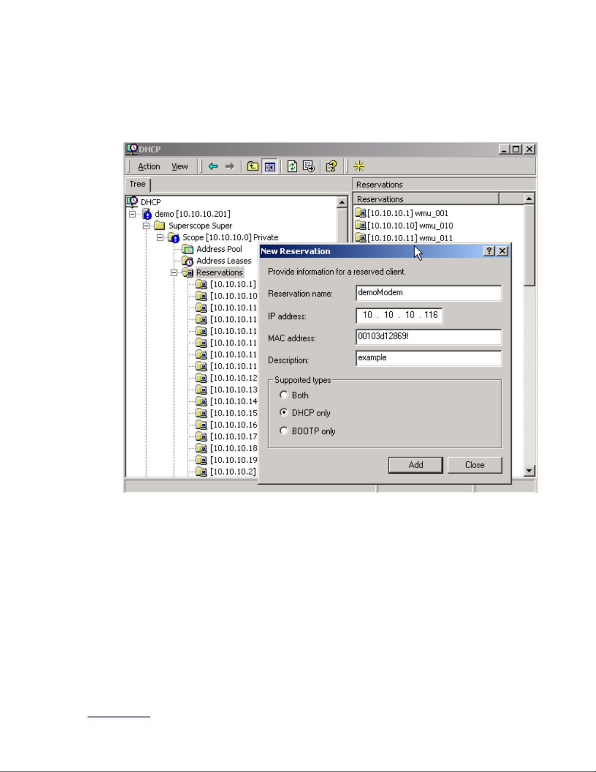
4. Enter the required information (see your system engineer for details) and
click the “Add” button.
NOTE: Make sure to select the “DHCP only” radio button
under “Supported Types”.
Figure 5-16: Enter the information for the new reservation
Page 53
System Configuration Guide
www.vyyo.com
Adding a Modem to the WMTS – p. 53
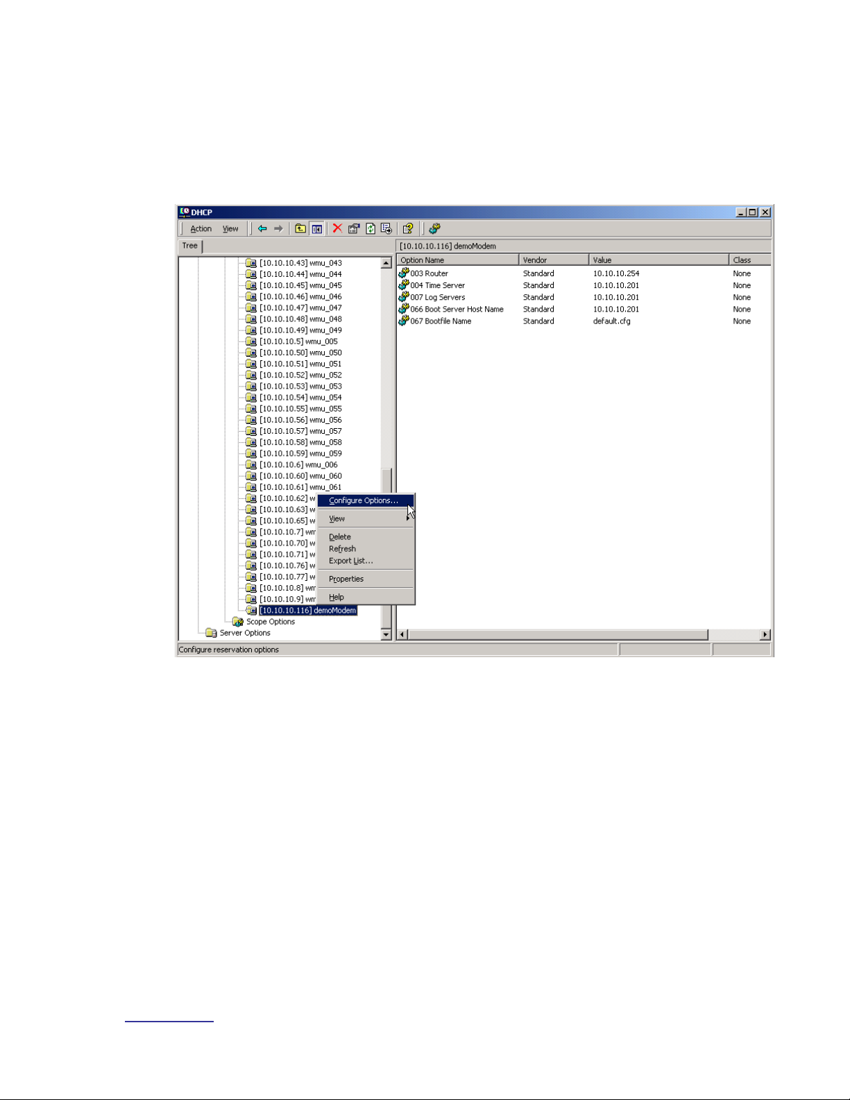
5. Now select the new reservation and right-click on the newly added
modem then select “Configure Options” to choose the modem
configuration file that will be downloaded to this modem. Observe that
five Options are shown in the right pane of the main window. These are
the default values.:
Figure 5-17: Navigate to the “Configure Options” action
Page 54

System Configuration Guide
www.vyyo.com
Adding a Modem to the WMTS – p. 54
6. Select the “General” tab in the popup window, scroll down to item “067”
and check (and select) the “Bootfile Name” checkbox to enter or change
the “boot” or modem configuration file name.
NOTE: Any of the other options may be changed using
this same procedure. These values must match the
physical setup of the network (as per the Network IP and
Network RF plans) to make the system work. If this
DHCP server is already in operation the default values
should be correct.
Figure 5-18: Enter the “boot” file name
Page 55

System Configuration Guide
www.vyyo.com
Adding a Modem to the WMTS – p. 55
TIP: You may verify that the modem properties have
been set correctly. Select the modem and right-click to
display the action popup window; then select “Properties”
to display and allow you to verify the modem information
entered previously.
Figure 5-19: Navigate to the Properties display for the selected modem
Page 56

System Configuration Guide
www.vyyo.com
Adding a Modem to the WMTS – p. 56
Tip: The modem information is displayed in this popup
window.
Figure 5-20: View the Properties for the selected modem
Page 57

System Configuration Guide
www.vyyo.com
Adding a Modem to the WMTS – p. 57
5.3 Configuring the WMTS
NOTE: Before you can perform this procedure you must
have previously edited the regtree.txt file, compiled it and
downloaded it to the WMTS to set its IP address. See
Chapter 7. Setting the WMTS IP Address.
This section assumes that you have previously installed
NMS Version 7. See Installing and Uninstalling the NMS
for brief instructions.
The upstream and downstream channels of the WMTS must be configured
before a modem can communicate with the WMTS. This is done using the Vyyo
Configuration Tool. Before proceeding, launch the Vyyo Configuration Tool as
described in Launching the Vyyo Configuration Tool.
5.3.1 Setting the WMTS Upstream Parameters
1. Expand the WMTS tree in the left pane of the Vyyo Configuration Tool
and select the Upstream Channel ID you wish to configure using the
mouse. The Channel ID refers to the physical port on the upstream RF
card that you are configuring. This connection is described in WMTS US
Port Mapping. In this example upstream channel 1 is selected and all of
its parameters are displayed in the right pane of the window.
You may change the frequency the modem is told by the WMTS to
transmit on (labeled “Tx Frequency”), the receive frequency that the
upstream RF port expects to receive the modem’s signal on (this is
labeled “Rx frequency”), its bandwidth, modulation, and the associated
downstream channels, antenna diversity and admin status as needed.
These parameters are transmitted by the WMTS as part of the upstream
channel descriptor (UCD) sent during the DOCSIS modem initialization
process. These parameters should be determined by the system
engineer responsible for the RF planning and are outside the scope of
this manual.
Page 58

System Configuration Guide
www.vyyo.com
Adding a Modem to the WMTS – p. 58
Set this to ‘up” to operate this
channel or “down” to turn it off
The modem
transmits on
this frequency
This WMTS upstream channel
will receive on this frequency
These are the WMTS
downstream channels
associated with this
WMTS upstream channel
Check this box unless your System
Engineer indicates otherwise
Check this box
Click here to save the new settings
Figure 5-21: Selecting and Setting Upstream Channel Parameters
NOTE: For Data Service Type, “Best effort channel” or
“CIR channel” are typically used for a data-only modem.
An “E1 channel” must be used when the modem supports
E1/T1 connections and data. These settings correspond
to the desired SLA (Service Level Agreement.)
The “Tx backoff” settings control the scheduling algorithms used in the upstream
channel. The default values should be used unless your system engineer has indicated
otherwise.
Ensure that the “Optimize channel parameters” box is checked. This causes the WMTS
to maximize the efficiency of the channel usage for the different types of modems
assigned to it.
Page 59

System Configuration Guide
www.vyyo.com
Adding a Modem to the WMTS – p. 59
7. Click on the Update button at the bottom left of the screen to save the
new settings. Click ”OK” when the folllowing confirmation popup window
appears.
Figure 5-22: Confirm the Update
8. You have now completed configuring the upstream channel. For a
summary of all of the upstream channels click on the “Upstream” item in
the left pane of the window.
Figure 5-23: Viewing the WMTS Upstream Channels Summary
Page 60

System Configuration Guide
www.vyyo.com
Adding a Modem to the WMTS – p. 60
5.3.2 Setting the WMTS Downstream Parameters
1. Select the WMTS Downstream Channel you wish to configure from the
left side of the window. In this example downstream channel 1 is
selected and all of its parameters are displayed in the right pane of the
window.
Bandwidth, modulation, and other parameters can be changed. Typically the
default values should be used with “Optimize channel parameters” unless
your system engineer indicates otherwise.
These parameters should be determined by the system engineer responsible
for the RF planning and are outside the scope of this manual.
Figure 5-24: Select the downstream channel and change its parameters
Page 61

System Configuration Guide
www.vyyo.com
Adding a Modem to the WMTS – p. 61
9. To permanently save the configuration to the WMTS click on the
“Update” button. Press the “OK” button on the popup window to confirm
the update.
Figure 5-25: Confirm the Update
10. You have now completed configuring the downstream channel. For a
summary of all the downstream channels click on the “Downstream” item
in the left pane of the window.
Figure 5-26: Viewing the WMTS Downstream Channels Summary
Page 62

System Configuration Guide
www.vyyo.com
Adding a Modem to the WMTS – p. 62
5.4 Setting the Modem’s Downstream Frequency
This section provides details on how to set the downstream frequency that the
modem listens on to begin its initialization sequence. Setting this value greatly
reduces the time it takes for a modem to complete its initialization sequence.
NOTE: the downstream frequency that is set using this
technique will not be saved in the modem until the
modem completes registration.
1. Connect a computer to the RJ45 modem connector using a standard RJ45 patch
cable.
2. Make sure your computer's IP address is set to 192.168.100.xxx, where "xxx" is
any value from 2 to 254. The subnet mask should be 255.255.255.0. You may
use any utility software on your computer that allows you to set these values.
3. All modems include a Telnet server with a fixed IP address of 192.168.100.1.
Follow the screens below to set the modem Downstream Frequency and view
the Downstream and Upstream settings.
The modem Telnet server has multiple levels of access privileges:
User – the standard level which permits viewing information
Operator – permits changing the downstream frequency
Note: The modem will accept typed settings while
simultaneously displaying and scrolling though feedback
information or messages. This behavior does not affect
setup. At present there is no procedure to turn off the
streaming messages issued by the modem.
4. Enter the password (obtained from your system engineer or a Vyyo
representative) on this screen.
Page 63

System Configuration Guide
www.vyyo.com
Adding a Modem to the WMTS – p. 63
Enter the user password here
when prompted.
Figure 5-27: Log In to the Vyyo WMU Telnet Server
Page 64

System Configuration Guide
www.vyyo.com
Adding a Modem to the WMTS – p. 64
5. This screen will be displayed after the password is correctly entered:
Figure 5-28: Successful Telnet Login
Page 65

System Configuration Guide
www.vyyo.com
Adding a Modem to the WMTS – p. 65
6. Type “su operator”, then press return. Now enter the operator’s password
(obtain this from your system engineer or a Vyyo representative) to access the
DOCSIS control commands.
Note: Return to user mode from operator mode at any
time by typing “su user” – no password is required to
return to user mode.
Figure 5-29: Switching to the Operator's Permission Level
Enter the operator password here
when prompted
Page 66

System Configuration Guide
www.vyyo.com
Adding a Modem to the WMTS – p. 66
7. Change to the DOCSIS Control subdirectory by typing “cd docsis”:
Figure 5-30: The “cd docsis” Command
Type “cd docsis” here
Page 67

System Configuration Guide
www.vyyo.com
Adding a Modem to the WMTS – p. 67
8. Type “goto_ds xxxxxxxxx” to set the Downstream Frequency, where “xxxxxxxxx”
is the frequency in Hertz.
NOTE: Your system engineer should provide you with
this value. This will now be the permanent fixed
frequency at which the modem will listen for a broadcast
from the WMTS. After a maximum of 30 seconds, the
modem LEDs should light up and remain lit. This
indicates that the modem has locked on to the
Downstream channel, is operating on the appropriate
Upstream channel, and is authorized for operation on the
WMTS.
Figure 5-31: Setting the Frequency to 743 Mhz (or 743000000, i.e., six
zeroes)
Enter the frequency here
Page 68

System Configuration Guide
www.vyyo.com
Adding a Modem to the WMTS – p. 68
9. To view the “operator” commands type “?”. The following figure shows the
“operator” commands.
NOTE: to get help on a particular command type “help
<command>”
Figure 5-32: Executing the “?” command to view the Operator commands
Page 69

System Configuration Guide
www.vyyo.com
Adding a Modem to the WMTS – p. 69
5.5 Verifying the Modem Downstream and Upstream
Status
1. View the downstream status after the modem has successfully
completed registration by typing “dsdiag” to verify that the change took
effect and the modem is operating correctly: “QAM = LOCKED” and
“FEC = LOCKED” should appear as the last two lines. You must have
“operator” access rights to do this.
NOTE: this will only happen if the modem is in a place
where it can establish RF connectivity to the WMTS, e.g.,
hooked up to the cable plant.
Figure 5-33: Viewing the Modem Downstream Status
Page 70

System Configuration Guide
www.vyyo.com
Adding a Modem to the WMTS – p. 70
2. View the Upstream Status after the modem has successfully completed
registration by typing “usdiag” to verify that the modem is operating
correctly. The parameters should be stable. You must have “operator”
access to do this.
Figure 5-34: Viewing the Modem Upstream Status
The modem has now established IP connectivity with the WMTS.
Type “usdiag” here
Page 71

System Configuration Guide
www.vyyo.com
Adding a Modem to the WMTS – p. 71
5.6 Using an HTTP Connection to View Modem
Operation
You may also view this information using an HTTP browser such as Internet
Explorer. All modems include an HTTP server at the same address as the
Telnet server. If the modem does not yet have an IP address assigned and
operating (i.e., completed registration), set your browser to browse the URL
http://192.168.100.1/ to get the status information.
Note: In order to use this facility, you must be connected
to the same LAN to which the modem is connected. This
would be 192.168.0.xxx with a subnet mask of
255.255.255.0 in the initial case.
5.6.1 Viewing the internal modem HTML pages:
1. Open the Web Browser application that is installed on your system.
Figure 5-35: Opening a Browser Window to view modem activity
11. Type http://192.168.100.1/ into the Address field at the top of the Browser
window and press “Enter”.
Figure 5-36: Entering the modem IP address into the Browser Window
Page 72

System Configuration Guide
www.vyyo.com
Adding a Modem to the WMTS – p. 72
12. Obtain the Operator user name and password from your System
Administrator or an authorized Vyyo representative. Enter the user name
and password in the appropriate fields, and click the OK button. The
Vyyo Connection page opens.
Figure 5-37: Entering the modem user name and password
Page 73

System Configuration Guide
www.vyyo.com
Adding a Modem to the WMTS – p. 73
13. Each informational page consists of two sections: A Menu box at the left,
which enables you to navigate between pages, and a Data area at the
right, which shows information specific to the system.
5.6.2 Viewing the Connection Page
To view the Connection page click the “Connection” option on the Menu box.
Figure 5-38: Selecting the Browser Connection option
Page 74

System Configuration Guide
www.vyyo.com
Adding a Modem to the WMTS – p. 74
The browser displays the Connection page which has five areas of information:
• Startup Procedure
• Downstream Channel
• Upstream Channel
• Assigned IP Address of the Modem
• Current System Time from the ToD Server.
Figure 5-39: Viewing the Browser Connection page
5.6.3 Viewing the Software Page
To view the Software page click the Software option on the Menu box.
Figure 5-40: Selecting the Browser Software option
Page 75

System Configuration Guide
www.vyyo.com
Adding a Modem to the WMTS – p. 75
The Software page displays modem Information and Status data.
Figure 5-41: Viewing the Browser Software page
5.6.4 Viewing the Security Page
To view the Security page click the Security option on the Menu box.
Figure 5-42: Selecting the Browser Status option
The browser displays the Security page.
You use the Security page if you wish to change your login password. To change
your Password, enter a new Password in the Password field, and enter it again
for verification in the Re-Enter Password field.
If you want to return to the factory default password, select the Yes option and
click Apply.
Page 76

System Configuration Guide
www.vyyo.com
Configuring a T1 Connection – p. 76
Chapter 6. Configuring a T1
Connection
NOTE: the data connection for the E1/T1 modem must
be setup as previously described in Chapter 5, Adding a
Modem to the WMTS
Three separate tools are necessary to configure a T1 connection:
The CMConfigFileEditor is used to set the modem QoS (also referred to as Class of
Service) in the modem configuration file downloaded during the modem initialization
phase.
The NMS (Castlerock SNMPc) tool is the Network Management System used to monitor
and reconfigure the network on an ongoing basis. It accesses a MIB database stored in
the WMTS as well as a local version residing in the controlling computer. It is used here
to set specific WMTS parameters by launching the Vyyo Configuration tool.
The Java™-based Vyyo Configuration Tool is necessary to set the E1/T1 parameters
of the WMTS when adding a new modem to the network.
These tools may be used as directed in any order. They are described in the
following sequence:
1. The CMConfigFileEditor is used to modify the modem configuration file
for T1 operation by adding a second Class of Service (the first Class of
Service was used for the data only connection). Instructions are also
given for setting/checking the upstream and downstream parameters
(which may have been previously set when configuring the modem for
data only operation).
2. The NMS tool is used to launch the Vyyo Configuration Tool to set the
WMTS upstream parameters, specifically the QoS (Quality of Service)
which is another name for the Class of Service. For older systems,
Instructions for using the Synoptics interface are given in Chapter 10,
Error! Reference source not found..
3. The Vyyo Configuration Tool is required to bind the T1 ports of the
modem to the T1 ports of the WMTS.
Page 77

System Configuration Guide
www.vyyo.com
Configuring a T1 Connection – p. 77
6.1 Configure the Modem for T1 Operation
In this section instructions are provided for using the CMConfigFile Editor to edit
the modem configuration file which will be downloaded to the modem. When the
edits on the following pages are complete, copy or move the modem
configuration file to the directory being used by the TFTP Server (usually this will
be something like “C:\vyyo\mic”). You may also save it directly to the TFTP
directory using the “Save” menu option of the CMConfigFile Editor.
NOTE: This file name must be bound to this modem’s
MAC address by using the appropriate DHCP tool for the
particular system being used (Edit the CM.SRC file if
ipLease is being used. If the Windows 200x Server
Edition DHCP Administrative tool is being used then set
the “bpBootfile” name to the name of the modem’s
configuration file).
1. Set the Downstream Frequency by selecting “General Parameters” then
double clicking on the “Downstream Frequency (Hz)” parameter as
shown. This is the frequency which the modem will use to receive
(downstream) transmissions from the WMTS. This procedure for
configuring the downstream channels is described in Setting the
Downstream Frequency.
Figure 6-1: Set the Downstream Frequency Value
Page 78

System Configuration Guide
www.vyyo.com
Configuring a T1 Connection – p. 78
4. Set the upstream channel ID using the same procedure. This is the
channel ID the modem will use to transmit upstream data to the WMTS.
The channel ID parameters are sent by the WMTS when it broadcasts
UCDs during the Obtaining Upstream Parameters phase (immediately
after the Downstream Synchronization phase) of the modem initialization
prcocess. This procedure for configuring the downstream channels is
described in Setting the WMTS Upstream Parameters.
Figure 6-2. Set the Upstream Channel ID
Page 79

System Configuration Guide
www.vyyo.com
Configuring a T1 Connection – p. 79
5. Create a second Class of Service (aka. QoS or Service ID). Select and
right-click “Class of Service”, then select the “Duplicate” option. This is
necessary to add the “Voice” (or “WAN”) service for the T1 connection.
NOTE: the first Class of Service was created previously
for the data only connection. This second Class of
Service is specifically for the T1 connection so make sure
it is setup that way. The same upstream channel is used
for both.
Figure 6-3. Duplicating the QoS Value
Page 80

System Configuration Guide
www.vyyo.com
Configuring a T1 Connection – p. 80
6. Observe that a second Class of Service has been added in the left
column of the window.
7. Select this second Class of Service, then right-click on the Maximum
Upstream Rate parameter and select “Modify” from the popup menu.
Figure 6-4. Modifying the Upstream Bit Rate Value
Page 81

System Configuration Guide
www.vyyo.com
Configuring a T1 Connection – p. 81
8. Now select “WAN Service/2048k” from the “Parameter” pane of the
popup window.
Figure 6-5. Choosing an Upstream Bit Rate Parameter
9. The corresponding parameters will appear on the right side of the popup
window.
Page 82

System Configuration Guide
www.vyyo.com
Configuring a T1 Connection – p. 82
10. Now select “WAN Service/2048K” in the left pane of the popup window
and then Click the “OK” button.
Figure 6-6. Choose Profile Setting
11. The display will return to the main window showing the new values set
above, as shown in Figure 6-7.
Figure 6-7.
Page 83

12. Select “Modem Capabilities” and turn on “Concatenation” and
“Fragmentation” by setting them to “1” (select each one then right-click to
popup the “Set Value” window) and clicking the “OK” button.
Figure 6-8. Setting Concatenation Value
Figure 6-9. Setting Fragmentation Value
Page 84

Vyyo Installation Guide
www.vyyo.com
Configuring a T1 Connection – p. 84
13. The display will return to the main window. The modem configuration file
is now configured for T1 operation. You should save this file. This
filename will be bound to the modem MAC address using the DHCP
Server tool as described in IpLease DHCP Server: Editing and running
the CM.SRC File. The same modem configuration file may be used for
several modems provided the Network RF Plan allows for this; see your
system engineer for details.
Figure 6-10. Main WMU Configuration File Editor Window
Page 85
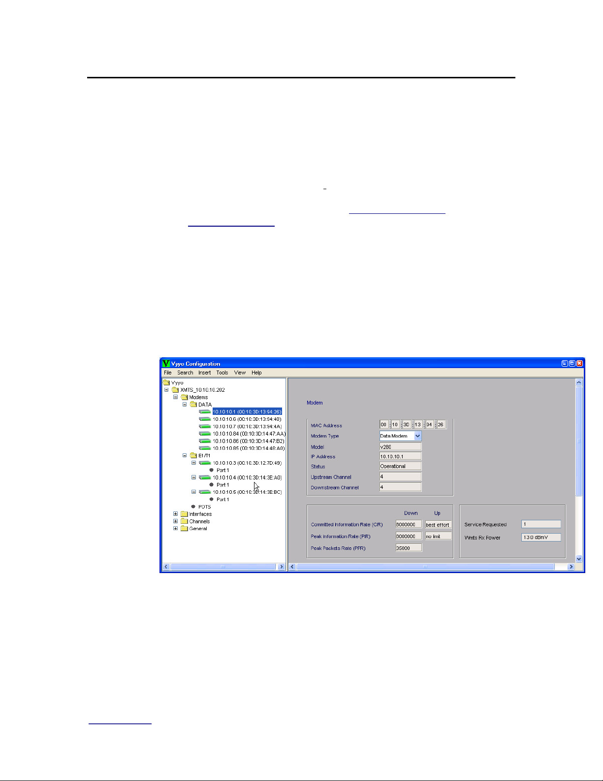
Vyyo Installation Guide
www.vyyo.com
Configuring a T1 Connection – p. 85
6.2 Adding the T1 modem to the WMTS T1 Interface and
Assign Port(s)
NOTE: The WMTS Upstream and Downstream
parameters must be configured prior to performing this
procedure. In particular the Upstream “Voice Service
Type” must be set to “WAN” for an E1/T1 channel. See
Configuring a T1 Connection. This is done using the Vyyo
Configuration Tool. Before proceeding, launch the Vyyo
Configuration Tool as described in Launching the Vyyo
Configuration Tool.
1. Expand the WMTS tree in the left pane of the main Vyyo Configuration
Tool window. Then expand “Modems” to obtain a more informative
version of the window. If the modem is already connected, the tool will
detect it automatically and it will appear in the list under
“Modems->E1/T1” or “Modems->Data” by its MAC address; in this case
skip to Step 4. Otherwise you must add the modem to the list by
continuing this procedure.
Figure 6-11: Expand the WMTS Tree
Page 86

Vyyo Installation Guide
www.vyyo.com
Configuring a T1 Connection – p. 86
2. Select the “Insert” menu option and choose “Modem”
Figure 6-12: Insert Modem
3. A popup window will appear to allow you to enter the modem type. From
the pulldown menu select “E1/T1 Modem”.
Figure 6-13: Select E1/T1 Modem
4. Confirm your selection
Figure 6-14: Confirm modem selection
Page 87

Vyyo Installation Guide
www.vyyo.com
Configuring a T1 Connection – p. 87
5. A new modem icon will appear on the WMTS tree window pane. Enter
the last three bytes of the Vyyo modem MAC address and press the
“Update” button then press “OK” on the popup window which confirms
the “success” of the update.
Note: The first three bytes of the Vyyo MAC address (the
vendor ID) are displayed both in the navigation tree on
the left and in the data entry window on the right.
Figure 6-15: Vyyo Modem Configuration Information
Figure 6-16: Update Success Confirmation
Enter the last part of
the Vyyo modem
MAC address here
Press the update button
after entering the MAC
address
Page 88

Vyyo Installation Guide
www.vyyo.com
Configuring a T1 Connection – p. 88
6. Enter the desired modem parameters and add the E1/T1 configuration
for the modem by clicking on the “Add E1/T1 Link” button. You may
cross connect an E1/T1 modem to another E1/T1 modem – see
Appendix E: Vyyo Configuration Tool – Additional Functions for this
procedure.
NOTE: Do this process once for the V311 modems and
twice for the V312 modems (the latter have two active
E1/T1 ports).
NOTE: the modem does not need to be active on the
network to perform this procedure as this is strictly a
configuration procedure. However, the modem will not
appear under its IP address unless it is already on the
network as a data modem, i.e., the DOCSIS IP portion of
the initialization has been successful.
Figure 6-17: Adding a new E1/T1 configuration for a modem
Page 89

Vyyo Installation Guide
www.vyyo.com
Configuring a T1 Connection – p. 89
7. When this screen appears, select the desired port on the WMTS E1/T1
interface card using the drop-down menu. This binds the T1 port on the
modem to its corresponding T1 port on the WMTS E1/T1 interface card
(inserted into the rear of the WMTS chassis).
Other parameters may be changed from the defaults shown in this
screenshot to create a “fractional T1” connection: the Framing parameter
must be set to ESF Framing or D4 Framing, and then you may set the
desired Time Slots range. Make sure that both the WMTS and Modem
port status are enabled.
Figure 6-18: Updating the Port Data
Select the port – all
assigned ports will
appear (only 1 in
this example)
Click the “Update” button
when done
To make this a fractional T1
connection select the specific T1
slots you wish to use by setting the
Framing parameter and choosing
the Time slot range
Select the desired WMTS port using
the pull down menu
Page 90

Vyyo Installation Guide
www.vyyo.com
Configuring a T1 Connection – p. 90
8. Now click on the “Update” button and press “OK” when the confirmation
popup window appears. Select “Refresh Modems” from the File menu to
refresh the modem icons (the new modem icon should change to green).
Figure 6-19: Updating the system for the new modem
Page 91

Vyyo Installation Guide
www.vyyo.com
Configuring a T1 Connection – p. 91
9. This screen will show the new modem and its connection to WMTS port
1 (in the Connections Table at the bottom). Note that the color of the
modem in the left window pane has now changed from red to green (if
the modem is online).
Figure 6-20: Viewing the new modem’s E1/T1 interface information
Page 92

Vyyo Installation Guide
www.vyyo.com
Configuring a T1 Connection – p. 92
10. For a summary of all modems and E1/T1 ports select the “E1/T1
Interfaces” item on the navigation tree in the left window pane
Figure 6-21: Viewing the E1/T1 Interfaces
At this point you have successfully connected the E1/T1 modem to the system
and data should be flowing between the modem and the WMTS.
Page 93

Vyyo Installation Guide
www.vyyo.com
Setting the WMTS IP Address – p. 93
Chapter 7. Setting the WMTS IP
Address
Note: Prior to performing this procedure the WMTS must
be connected to the “download” computer serial port via
the lower COM port (COM2) on the WMTS Control and
Forward card.
The WMTS must also be connected to the same LAN
subnet as the computer using its RJ45 connector on the
same (Control and Forward) card.
Tip: The procedure used to download the Regtree file via
the LAN connection may also be used to download other
files to the WMTS, such as new versions of the software.
First, the XmtsConfig.exe tool is used to set a temporary IP address
for the WMTS. This IP address allows the WMTS to appear on the
LAN subnet and communicate with the servers (which are on the same
network). The serial port connection is used to set the temporary IP
address and the LAN connection is used to perform the actual
download (via the temporary IP address previously set using the serial
port connection). After the modified version of Regtree (containing the
PERMANENT IP address of the WMTS) is downloaded and the WMTS
is restarted, the WMTS will be accessible via its PERMANENT IP
address.
Next, we will be modifying regtree.txt to contain the permanent WMTS
IP address, then compiling regtree.txt into regtree.rtr and downloading
it. The download is made by specifying regtree.rtr in the “Version File”
field of the XmtsConfig.exe tool and making sure that regtree.rtr (the
compiled version of regtree.txt) is copied into the TFTP file transfer
folder.
1. Locate the file “regtree.txt” and open it using a standard text editor such
as Notepad (do not use the XmtsConfigFileEditor for this as it does not
allow editing of the necessary entries). There may be several versions of
the Regtree file available (e.g., “regtree_data.txt”, “regtree_t1.txt”, etc.)
so ask your system engineer which one to use, then copy and rename it
to “regtree.txt” since that is the file which SETIP.bat expects as its input
file. Scroll down (or use the “Find” function from the menu) to the entry
“CmtsIPAddress” which is shown as 10.10.10.210 in this example. The
default network address for Vyyo equipment is 10.10.10.xxx. Your
system engineer should be able to provide the following information
required to configure the WMTS:
Page 94

Vyyo Installation Guide
www.vyyo.com
Setting the WMTS IP Address – p. 94
• WMTS IP address
• Gateway computer (used for downloading) IP address
• Gateway computer subnet mask
• IP addresses of any other computers that are permitted to
access the WMTS remotely
2. Change the “CmtsIPAddress” as desired: this is the WMTS’s
permanent IP address which will be downloaded later using the
XmtsConfig tool.
3. Change the two lines immediately following this line if necessary: the
“GatewayIPAddress” (the address of the gateway computer or router)
and the “CmtsSubnetMask”.
4. Change DevNMAccessIP1 and DevNMAccessCommunity for remote
control as appropriate in Regtree.txt. Up to five IP addresses may be
defined here. The first one should be the same as that of the Gateway
computer or router used in the previous step. If you wish to add
additional remote computers: duplicate the three lines for
DevNMAccessIP1 and DevNMAccessCommunity1 and
DevNMAccessControl1 for each additional remote computer, change
the numbers so that you have DevNMAccessIP2,
DevNMAccessCommunity2, DevNMAccessControl2 for the second
computer and so forth up to the fifth remote computer. Then change the
corresponding IP addresses for DevNMAccessIP2 and so forth.
Note: No other edits should be necessary in this file,
although the default frequencies for all the upstream and
downstream channels are initialized in this file and may
be changed if necessary.
Page 95
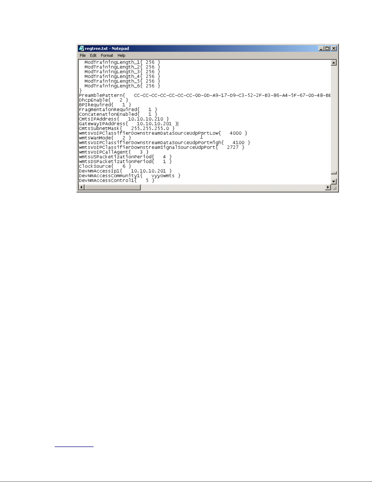
Vyyo Installation Guide
www.vyyo.com
Setting the WMTS IP Address – p. 95
Figure 7-1. Regtree.txt File Contents
Page 96

Vyyo Installation Guide
www.vyyo.com
Setting the WMTS IP Address – p. 96
5. Now compile regtree.txt by executing SETIP.bat which should be in the
same directory as regtree.txt. SETIP.bat is a batch file that converts
regtree.txt from text to a special format read by the WMTS. The resulting
file will be named RegTree.rtr.
Figure 7-2. Setip.bat
Page 97

Vyyo Installation Guide
www.vyyo.com
Setting the WMTS IP Address – p. 97
6. Locate the Regtree.rtr file and copy it to the directory (download path)
that is used by the TFTP server to get the requested download files (the
download directory):
Figure 7-3. Regtree.rtr Location in TFTP Root Directory
Page 98
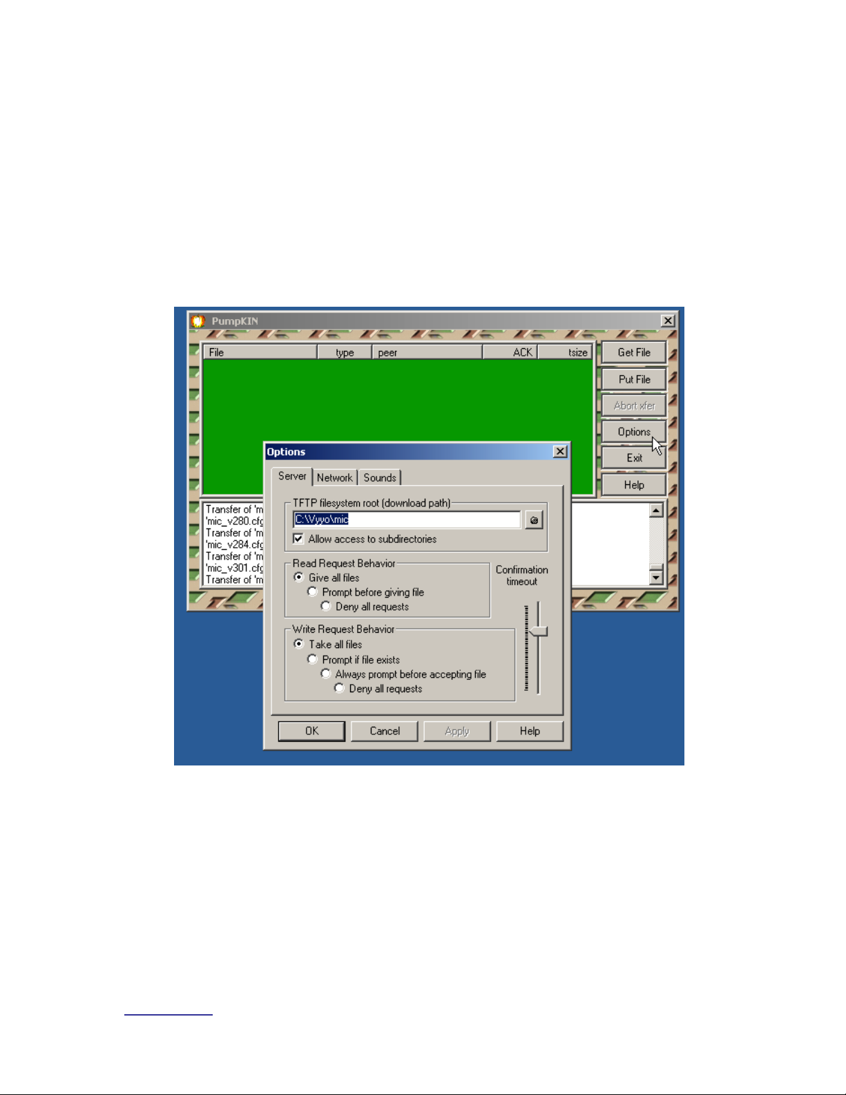
Vyyo Installation Guide
www.vyyo.com
Setting the WMTS IP Address – p. 98
7. Open the TFTP server: in this example we use Pumpkin.exe. You may
bring up the Options dialog window by clicking on the “Options” button.
This will allow you to change the download directory.
Note:The file RegTree.rtr must be copied to the TFTP
server download path, “C:\Vyyo\mic” as shown in this
example since this is the directory where the TFTP server
finds the requested files to be downloaded. You may
change this path to suit your particular directory layout.
To save the TFTP server download path as the default
value, exit Pumpkin then restart it.
Figure 7-4. PumpKIN TFTP Settings
Page 99

Vyyo Installation Guide
www.vyyo.com
Setting the WMTS IP Address – p. 99
Note: Observe that RegTree.rtr has been copied to the
TFTP download directory (C:\Vyyo\mic) used in this
example:
Figure 7-5. Regtree.rtr, Located in TFTP Root or Specified Download
Directory
Page 100

Vyyo Installation Guide
www.vyyo.com
Setting the WMTS IP Address – p. 100
8. Open the XmtsConfig.exe tool to perform the download to the WMTS.
This tool is typically located in the “…\Tools\XmtsConfig” directory of the
released software.
9. When the initial window appears right-click to expose a popup window
from which you must select “Activate”.
10. This will enable the screen for one minute, after which you must repeat
this procedure to re-activate the screen. The one minute timeout
prevents accidental downloads and restarts.
NOTE: You may have to “activate” the screen and
“connect” (explained in the next step) to the WMTS
several times during this procedure.
Figure 7-6. WMTS Configuration Tool
 Loading...