

Page 1
V284+C
W
IRELESS MODEM UNIT
User’s Guide
A Vyyo Inc. Technical Document
Version 1.1.5
P/N 9090-096
Page 2

Vyyö V284+C WMU User’s
Copyright and Trademark Information:
© 2005 Vyyo Inc. All rights reserved.
Vyyo Inc. reserves the right to alter the equipment specifications and descri ptions in
this publication without prior notice. No part of this publicati on shall be deemed part
of any c ont ract or war rant y unle ss s pecif ical ly inc orpor ated by r eferen ce in to s uch
contract or warranty.
The information contained herein is merely descriptive in nature, and does not
constitute a binding offer for the sale of the product described herein. Any use of
the Vyyo Inc. logo or tr ademarks is forbidden wit hout prior written approval from
Vyyo Inc.
All trademarks mentioned herein are the pr operty of their respective owners . Vyyo
Inc.’s trademarks include, but are not lim i ted to, “Vyyo” and “Wireless liberty for all.”
i
www.vyyo.com
Page 3

FCC Compliance Statement
Vyyö V284+C WMU User’s
NOTE: This equipment is authorized under FCC ID:
PLUS-C
to operate in the C Block of the Upper 700 MHz Band
PBJV284-
pursuant to Part 27 of the FCC’s rules.
In addition, this equipment has been tested and found to
comply with the limits for a Class B digital device pursuant to
Part 15 of the FCC Rules.
These limits are designed to provide reasonable protection
against harmful interference in a residential installation. This
equipment generates uses and can radiate radio frequency
energy and, if not installed and used in accordance with the
instructions, may cause harmful interference to radio
communications. However, there is no guarantee that
interference will not occur in a particular installation.
If this equipment does cause harmf ul interference to radio or
television reception, which can be determined by turning the
equipment off and on, the user is encouraged to try to correct
the interference by one or more of the following measures:
• Reorient or relocate the antenna.
• Increase the distance between the equipment and
receiver.
• Connect the equipment into an outlet on a circuit different
from that to which the receiver is connected.
• Consult the dealer or an experienced radio/TV technician
for help.
Warning!
Changes or modifications to this equipment not expressly approved by
Vyyo, Inc. could void the user’s authority to operate the equipment.
Warning!
This product was tested and shipped with shielded coaxial cable and
Category 5 Ethernet cable equipped with a shielded RJ-45 connector.
These cables must be used with the unit to ensure compliance.
ii
www.vyyo.com
Page 4

Vyyö V284+C WMU User’s
CONTENTS
1 Overview and Purpose .....................................................1
1.1 Purpose of This User’s Guide ............................... ...........1
1.2 Target Audience...............................................................1
1.3 Vyyo.................................................................................1
2 Modem Features and Components ................ ... ... .... ... ....2
2.1 Front Panel Indicators... ... ... ... ... ................... ... ... .... ... ... ... .2
2.2 Rear Panel Connector s. ... ... ... ... ... .... ... .................. .... ... ... .4
3 Using the Modem ..............................................................5
4 Technical Specifications ..................................................6
5 Problem Troubleshooting ............................ ... ... ... .... .......8
6 Warranty Information.. ... ... ... ... ... ................... ... ... ... .... ... ... .10
7 FCC Declaration of Conformity........................................11
8 Contacting Vyyo................................................................12
iii
www.vyyo.com
Page 5
Vyyö V284+C WMU User’s
1 O
VERVIEW AND PURPOSE
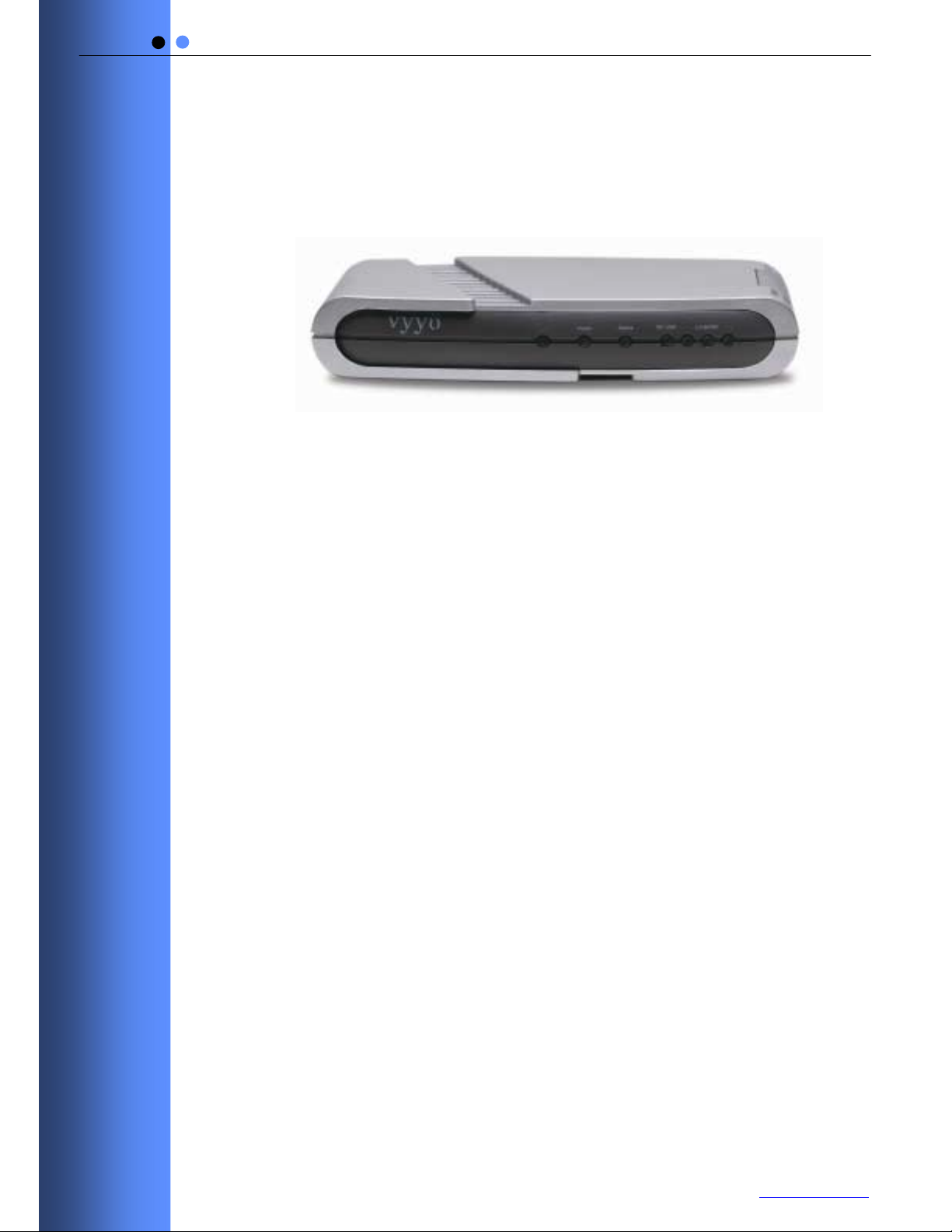
Welcome to the User’s Guide for the Vyyo Inc. V284+C
Modem.
Figure 1-1: The Vyyo V284+C Wireless Modem Unit
1.1 Purpose of This User’s Guide
The purpose of this User’s Guide is to provide clear and
concise instructions for operating the Vyyo Inc. V284+C
modem.
1.2 Target Audience
This User’s Guide is intended for users of the V284+C
modem.
1.3 Vyyo
Vyyo Inc. provides fixed wireless broadband end-to-end
telephony and high-speed data connections to business and
residential subscribers. Vyyo Inc. technology uses point-tomultipoint architecture to deliver circuit-switched telephony
and data over IP to commercial and private customers
throughout the world.
1
www.vyyo.com
Page 6

Vyyö V284+C WMU User’s
2 M
ODEM FEATURES AND COMPONE NTS
The V28 4 +C modem off er s the foll owing f e atures :
• Point-to-multipoint broadband wireless Internet access
• Superior operations over a wide range of modulation formats
and IF bandwidths, including noisy channels
• Easy installation
• Robust RF performance
• Internal radio for UHF bands
2.1 Front Panel Indicators
Four Light E mitting Diode (L.E.D.) indicators are located at
the front of the modem.
The L.E.D.s provides information abo ut the type and status of
modem operations, as described in Table 1.
Figure 2-1: V284+C WMU F ront Panel L.E.D. Indicators
2
www.vyyo.com
Page 7

Table 2-1: L.E.D. Status and Functions
L.E.D. Indicator Function
Vyyö V284+C WMU User’s
POWER
• On = Power On
• Off = Power Off
• Flashing = Fatal Error
STATUS
• On = Modem is connected to the Internet
• Off = Modem is not connected to the Internet
RF LINK When Status L.E.D. is Off:
• RF On = The downstream link is operational
• RF Off = The modem has not yet begun
downstream acquisition, the
downstream link is idle, or there is a
problem with data reception
• RF Flashing = Downstream link is being acquired
When Status L.E.D. is On:
• RF Flashing = Data is transferring in either in the
Upstream or Dow nstream direction
LAN&
USB
• On = The LAN link is operational
• Off = The LAN link is not operational
• Flashing = Data is transferring t o or from the LA N
3
www.vyyo.com
Page 8

2.2 Rear Panel Connectors
There are three connectors located on the rear panel of the
V284+C modem.
Vyyö V284+C WMU User’s
Power
LAN
Figure 2-2: V284+C WMU Rear Panel Connectors
RF Link
Connector or Button Function
POWER Connect the 9 volt external power source here.
LAN Connect an RJ-45 E thernet cable to this port.
The other end of the cable can be connected to
the subscriber’ s c omputer or an Ethernet hub or
switch.
Cable Connect this F-type connecto r to the UHF
antenna.
Table 2-2: V284+C Rear Pa nel Connectors
4
www.vyyo.com
Page 9

Vyyö V284+C WMU User’s
3 U
SING T HE MODEM
Follow the steps below to use the modem properly.
To use the modem:
1 Check that the computer with which you are using the
V284+C modem contains a working E thernet network card,
and has the following software installed and operational:
• Microsoft Windows 95 operating system or later
• Access to the Internet
• A standard Internet browser application
• The Telnet communications utility
2 Attach your computer to the modem’s LAN port with the
included RJ-45 Ethernet cable.
3 Connect t he antenn a cable to the CABLE connector on the
rear of the modem.
4 Plug th e 9-Volt modem power supply jack into t he POWER
socket on the rear of the modem, and plug the power
supply transformer unit into a standard electrical wall outlet.
Note: As with any household electrical device, avoid the risk of accidental
elect r ical shock. Make sure that your hands are completely dry and that there is
no moisture on the floor or other surfaces in the immediate area of the electrical
wall outlet.
After connecting the power adapter to the modem, verif y that
the three green front pan el LEDs light up for approximate ly 2
seconds before going out.
The orange POWER LED at the left of the front panel lights
up and remains lit, indicating that the modem is powered up.
Hazard: As with any mobile transmitting equipment, avoid of getting the human
body closer than 20 Cm to the modem or the antenna.
5
www.vyyo.com
Page 10

Vyyö V284+C WMU User’s
4 T
ECHNICAL SPECI FICA TIONS
General
Dimensions 5.25 x 4.25 x 1.00 in. (13 x 11 x 2.5 cm)
Operating
Temperature
Power 800 mA a t 9V
Power Supply 110 - 220 VAC
LED Indicators (4 ) Power, Status, RF/Link, LAN/USB
Interface
Data Interface RJ45 – 10/100 baseT Ethernet full/half duplex
USB [Not currently supported]
IF Interface 75 ohm Type F Female Connector
IF
32 to 112° F (0 to 45° C)
Downstream
/RFCharacteristics
Frequency Range 740 – 746 MHz Downstream Receive
Channel Bandwidth 1.75, 2, 3, 6 MHz
Modulation Format QPSK, 16 QAM, & 64 QAM
Data Rates 0.55 – 1 .65 Mbps
Rx Sensitivity (dBm) BW
6 -75 -81 -87
3 -78 -84 -90
1.75 -81 -87 -93
IF
(MHz)
Upstream
64 QAM 16 QAM QPSK
/RFCharacteristics
Frequency Range 710 – 716 MHz
Channel Bandwidth 200, 400, 800, 1600,3200 kHz
Modulation Fomat QPSK & 16QAM
Data Rates (Raw) 320 kbp s – 10.24 Mbps
RF A mpl ifi e r P1 dB 32 dBm
Linear Output Power 27.8 dBm
6
www.vyyo.com
Page 11

Vyyö V284+C WMU User’s
Service
Network Management Protocol: SNMP
MIB: RFC1213, RFC1493, RFC2233, RFC2669,
Provisioning: As per DOCSIS
Security Link Layer
Key
Upstream QoS Committed
Peak
Downstream QoS Supports CIR and PIR
IP Protocols Network
VoIP: G711, G729, G723
Transport
Application
# IP Data Services 64 CPE MAC
Ordering Info
220 VAC Powe r
Supply
11 0 VAC Pow er
Supply
Encryption:
Distribution:
Information
Rate (CIR)
Information
Rate (PIR)
Protocols:
Protocols:
Protocols:
Addresses
Part Number
3BR0013-A
3BR0012-A
RFC2670, DOCSIS Privacy MIB
DES CBC, 40 and 56 Bits per user
Two-layer key distribution protocol, which
includes DES-ECB and RSA public key
encry pt i o n an d H M A C-SHA1 aut h orizat i o n
Supported
Supported
IP, ICMP, ARP, PPPoE, 802.1Q/p, IP
Multicast
TCP, UDP, RTP
SNMP, TFTP, DHCP
7
www.vyyo.com
Page 12

Vyyö V284+C WMU User’s
5 P
If you encounter problems with your modem, try the following
steps.
1 Check for damage to the external modem casing during
2 Verify that the 9-Volt modem power supply jack is
3 Verify that the RF coaxial cable is connected properly to
4 Verif y that the modem LAN LED is illuminated and that the
Following are further steps you can take to identify and
correct modem problems.
ROBLEM TROUBLESHOOTING
shipping or installation. If you see visible damage, the
modem may need replacement.
connected to the modem POWER connector on the rear of
the modem, and that the modem power supply is
connected to a known-good AC power outlet.
the modem CABLE connector.
LAN cable is connected to a working Ethernet net work port
on the PC.
# Problem Description Possible Cause Potential
Resolutions
1 The LEDs do not light
up.
• The DC plug
may not be
installed
correctly.
• The power
supply may not
be connected to
an active AC
power outlet.
• The power
supply may be
faulty.
1. Check the
connection of
the power
supply. Chec k
the wall outlet
with a working
lamp to see if
there is current.
2. Test the power
supply using
another
modem.
3. Replace the
power supply if
necessary.
8
www.vyyo.com
Page 13

Vyyö V284+C WMU User’s
# Problem Description Possible Cause Potential
Resolutions
2 The LAN&USB LED
does not light up.
• The connection
between the
modem and the
PC may be
faulty.
1. Check the
10/100BaseT
cable
connection.
2. Check the
network
configuration:
IP address,
Gateway,
DHCP, and
DNS.
3. Reset the
modem by
disconnecting
and
reconnecting
the power.
4. Replace the
NIC Ethernet
card.
5. Test the
connection
using another
modem or
network device.
3 The RF LINK LED is
blinking or off, and the
STATUS LED is off.
• There is no RF
signal.
1. Check coaxial
cables, power
inserter,
transformer,
antenna
direction and/or
splitter.
9
www.vyyo.com
Page 14

Vyyö V284+C WMU User’s
6 W
The Vyyo Inc. Limited W arranty and related information can
be found in the terms and conditions and/or other contracts
under which this product was purchased.
ARRANTY INFORMATION
10
www.vyyo.com
Page 15

Vyyö V284+C WMU User’s
7 FCC D
The Responsible Party for this equipment is:
Company: VYYO Inc.
Address: 4015 Miranda Avenue, Palo Alto, CA. 94304
Country: USA
Telephone number: 001-650-3194037
Fax number: 001-650-3194066
VYYO Inc. hereby certifies and declares that the following equipment:
complies with Part 15 of the FCC Rules as an unintentional radiator. With respect
to its status as a Part 15 Class B digital device, operation of this equipment is
subject to the following two conditions: (1) this device may not cause harmful
interference, and (2) this devic e must accept any interference received, inclu ding
interference that may cause undesired operati on.
Executed at:
VYYO Inc
4015 Mirand a Avenu e
Palo Alto, CA. 94304
USA
VYYO Inc.
ECLA RATION O F CONFOR MIT Y
Brand Type Product description
VYYO V284+C UHF WIRELESS MODEM
on September 20, 2005
Dr. Mike Ritter
VP, Marketing
11
www.vyyo.com
Page 16

Vyyö V284+C WMU User’s
8 C
ONTACT ING VYYO
For further information about t he V284+C WMU or other V yyo
products, visit the Vyyo Website at:
www.vyyo.com
.
12
www.vyyo.com
 Loading...