


www.vympel.de
Hygrovision mini
Dew point analyzer
Operating Manual
Precision | Economy | Safety

2
Contents
1! Analyzer description.............................................................. 4!
1.1! Purpose and applications.............................................................. 4!
1.2! Technical characteristics............................................................... 5!
1.3! Measurement principle.................................................................. 6!
1.4! Construction.................................................................................. 6!
1.4.1! The Hygrovision mini’s main components and controls ............................8!
1.4.2! Hygrovision mini power supply..................................................................9!
1.4.3! Control and display elements ..................................................................10!
1.4.4! Turning the Hygrovision mini on and off..................................................11!
1.5! Menu of the Hygrovision mini...................................................... 12!
1.5.1! Menu structure ........................................................................................12!
1.5.2! Main menu...............................................................................................13!
1.5.3! “Mirror cleaning” ......................................................................................13!
1.5.4! “Measuring the dew point: Тdp”................................................................14!
1.5.5! “Settings” .................................................................................................15!
1.5.6! Status of the battery charge ....................................................................16!
1.5.7! Program codes ........................................................................................17!
1.6! Accessories and additional equipment ....................................... 18!
1.6.1! Battery charger........................................................................................18!
1.6.2! Sample gas delivery system....................................................................18!
1.6.3! Through-flow control system ...................................................................19!
1.6.4! Particle filter.............................................................................................19!
1.6.5! Filter for the control of heavy hydrocarbons ............................................20!
1.6.6! Sample extraction set..............................................................................20!
1.6.7! Supplemental cooling system..................................................................20!
1.7! Hygrovision mini set.................................................................... 21!
1.8! Explosion safety provisions......................................................... 23!
1.9! Markings ..................................................................................... 24!
1.10! Packaging ................................................................................. 24!
2! Proper operation of the Hygrovision mini............................ 25!
2.1! General requirements ................................................................. 25!
2.1.1! Unpacking and visual inspection of the device........................................25!
2.1.2! General requirements for the sample extraction site ...............................25!
2.1.3! General safety measures ........................................................................25!
2.2! Connecting the analyzer ............................................................. 26!
2.3! Using the Hygrovision mini ......................................................... 27!
2.3.1! Preparing to take dew point measurements............................................27!
2.3.2! Visual identification of water condensation .............................................28!
2.3.3! Visual identification of hydrocarbon condensation .................................29!
2.3.4! Rough dew point measurement ..............................................................31!
2.3.5! Measuring water and hydrocarbon dew points.......................................33!
2.3.6! Supplemental cooling ..............................................................................37!
2.4! Deinstallation of the Hygrovision mini ........................................ 38!

3
3! Maintenance ........................................................................39!
3.1! Function tests ..............................................................................39!
3.1.1! Check the status of the battery charge ................................................... 39!
3.1.2! Check the condensation mirror............................................................... 40!
3.1.3! Check that the thermoelectric battery – TEB (Peltier element) is
functioning .......................................................................................................... 40!
3.1.4! Check the lighting systems ..................................................................... 40!
3.1.5! Perform a leak test.................................................................................. 41!
3.2! Maintenance procedures .............................................................41!
3.2.1! Servicing the power supply unit IP-01 .................................................... 41!
3.2.2! Cleaning the condensation mirror........................................................... 41!
3.2.3! Checking the efficiency of the thermoelectric battery (TEB).................. 43!
3.2.4! Replacement of the particle filter ............................................................ 44!
3.2.5! Calibrating the Hygrovision mini ............................................................. 44!
3.3! Troubleshooting malfunctions......................................................45!
3.4! Error message codes...................................................................46!
4! Markings ..............................................................................47!
5! Packaging............................................................................47!
6! Storage ................................................................................47!
7! Transportation .....................................................................48!
8! Recycling .............................................................................48!
Anlage А...................................................................................49!
Factory settings ...................................................................................49!
Appendix B ...............................................................................50!
Sample extraction system....................................................................50!
Appendix C...............................................................................51!
Membrane Filter (KRAY6.457.022) .....................................................51!
Function.............................................................................................................. 51!
Description ......................................................................................................... 51!
Membrane .......................................................................................................... 51!
Technical Data ................................................................................................... 52!
Recommended installation and usage ............................................................... 52!
Anlage D...................................................................................54!
Examples of the appearance of water and hydrocarbon
condensation .......................................................................................54!
Appendix E ...............................................................................57!
Appendix F ...............................................................................58!

4
1 Analyzer description
1.1 Purpose and applications
The Hygrovision mini is a compact analyzer designed to measure the dew points of water and hydrocarbons.
This portable hygrometer (hereafter also analyzer) is an instrument that is designed to
directly measure dew point temperatures by means of a temperature-controlled mirror.
Hygrovision mini areas of application:
⇒ Spot check measurements in the field
⇒ Check the operational performance of permanently installed Hygrometers
⇒ Confirm previous measurement results
⇒ Regularly measure water and hydrocarbon dew points directly in locations that are
not equipped with automatic through-flow hygrometers or where no such instruments
can be permanently installed.
⇒ Monitor various products as well as working and manufacturing processes (for exam-
ple, drying and vacuuming of facilities, systems, damp presses, steamers, regenerators, evacuators, etc.)
Hygrovision analyzers can be used in a variety of sectors including the gas, oil and chemical
industries, metallurgy, power generation, instrument engineering and many other fields, in
order to provide quality control of production processes where water and hydrocarbon dew
point values are of relevance.
The analyzer is certified “explosion-proof” as defined by EN 60079-0:2009 and it has a
“flameproof enclosure” in accordance with EN 60079-1:2007. The Hygrovision mini has
an “intrinsically safe power circuit” as per EN 60079-11:2007 and is labelled II 2G
Exd [ib] IIB+H2 Т5. The analyzer can be deployed in designated explosion risk areas of
indoor and outdoor installations in accordance with EN 60079-14:2008 and in other explosive areas where the use of electrical equipment is controlled by regulation.
5
1.2 Technical characteristics
Table 1
Water
≥ -50 °C (T
housing
)
Measurement range:
Hydrocarbons
≥ -50 °C (T
housing
)
Water
±1 °C
Absolute error
Hydrocarbons
±1 °C
Recommended volume of
sample gas stream
0.3 – 0.5 N L/min
9 – 12.6 V
Power supply: voltage
current / power requirement
4 Ah / 15 W
Battery charge life
Min. 12 h
Operating temperature range
-10 °C – +50 °С
Ambient humidity
Max. 98% at < + 35°C
Operating pressure
< 100 bar
Sample gas temperature
-20 °C – +50 °C
Enclosure protection per
IEC 60529
IP 54
Dimensions (without Microscope)
253x120x110 mm
Weight (without replacement
parts and accessories)
4 kg
Suitable installation
In closed rooms or in open areas
(explosion hazard zones)
Connection to the sample
gas delivery piping
Swagelok connector for pipes (tubes) with
an outer diameter of 6 mm
Service life:
- Analyzer*
10 years
- Battery
300 charging cycles
max. of two years
* - with regular maintenance and replacement of parts subject to wear

6
1.3 Measurement principle
The Hygrovision mini analyzer registers the dew point of water or hydrocarbons in a
gaseous mixture according to the principle of direct measurement, utilizing a mirror that
can be heated and cooled.
The measurement process involves monitoring the surface of the mirror and noting the temperature at the moment condensation forms on its surface.
In addition, the observation process is enhanced by the availability of two different lighting systems for illuminating the dielectric condensation mirror.
During the measurement cycle the reflectivity of the mirror is monitored. When the dew
point is reached reflectivity decreases as a condensation film forms. The temperature
(T) at which this happens is the dew point.
The analyzer is equipped with an achromatic 40-power microscope for observing the
surface condition of the mirror. In addition, there are two options for illuminating the
mirror: vertical and side lighting.
• Vertical lighting can be used for the visual registration of the water and hydrocarbon dew points.
• Side lighting is used specifically for the visual registration (confirmation) of the
dew point of water only.
The low angle of this illumination increases the optical intensity created by the scattering of light rays striking water condensation. This effect makes it possible to register
condensation earlier and with absolute clarity.
The mini is outfitted with a button pad that serves as the control interface. For example, it is
used to manually switch between lighting systems during the measurement process and to
regulate the mirror temperature. The temperature at which a clear condensation film forms
on the mirror’s surface is also fixed using this button keypad.
1.4 Construction
The Hygrovision mini analyzer has an explosion-proof design. For more information
about explosion proofing see point 1.8.
The analyzer consists of a cold body housing, a high-pressure gas delivery system,
and an optical system.
The optical system includes a microscope and two lighting elements: one mounted
perpendicular to the mirror and one at a low angle.
The housing body of the analyzer includes an electronics unit and a measurement
cell. In order to support autarkic operations, the body of the mini includes a battery
compartment designed for the mini’s rechargeable battery.
The measurement cell, the gas delivery system, and the microscope, combined form
the measurement chamber. The measurement chamber is designed to accommodate
a working pressure of 100 bar.

7
The measurement cell includes the temperature-controlled condensation mirror, which
has an integrated thermal sensor, a thermoelectric battery, and a light emitting diode
for providing the side illumination.
The gas delivery system guides the sample gas over the temperature-controlled mirror in the measurement cell. This system includes a small observation window for
monitoring the condensation process and a particle filter to protect against contamination.
The microscope is mounted directly onto the gas delivery system. The vertical lighting
system is integrated into the microscope.
The electronics unit is made up of the liquid crystal display, the replaceable power
source (battery), and a four-button control unit (button pad). Via the four-button control
pad, the electronics unit makes it possible for the Hygrovision mini user to control how
rapidly the condensation mirror is cooled and heated. The button pad is also used to
turn the analyzer on and off, select the illumination system, and enter other operating
commands.
Data from the last measurement as well as system information are shown on the Liq-
uid Crystal Display (LCD).
A charging unit is delivered with the analyzer for recharging the battery .

8
1.4.1 The Hygrovision mini’s main components and
controls
Illustration 1
1) Locking lid of the battery compartment
2) Sample gas inlet nozzle
3) Padded eyepiece
4) Mirror illumination cable
5) Sample gas outlet nozzle
6) Ventilation channel for supplemental housing cooling
7) Locking mechanism for the electronics unit cover
8) LCD screen
9) Extendable handle
Illustration 2
10) Control unit

9
11) Housing body
12) Ventilation channel for supplemental mirror cooling
13) Focus control ring
14) Battery compartment lid locking mechanism
1.4.2 Hygrovision mini power supply
The analyzer is equipped with an independent source of electricity:
power supply unit IP-01 (battery).
Attention!
The battery should only be charged using the
specially designed charging unit.
1.4.2.1.1 Important technical data:
Table 2
! Battery type
⇒ LIR18650 (Lithium-Ion Li-Ion);
! Number of cells
⇒ 6
! Nominal voltage
⇒ 11.1 V
! Discharge current
⇒ max. 3A
! Electrical capacity
⇒ 14,400As
! Standard
service life
⇒ min. of 300 charge/recharge cycles; max. 2 years
! Operating
conditions
⇒ -20°C to + 60°C
A charging unit is incuded with the delivery of the Hygrovision for charging the IP-01
battery.
10
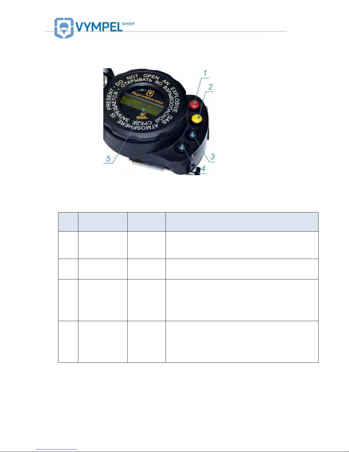
1.4.3 Control and display elements
Illustration 3
Refer to the table below for the function(s) of individual buttons
Table 3
The four-button control unit is used to operate and adjust the analyzer. The button pad
is located to the right of the LCD screen (pos. 1 to 4, illus. 3)
The buttons serve different functions depending on the control mode selected.
These functions are listed in table 2.
Pos.
Description
Color
Function
1
“Menu”
Red
Analyzer on/off;
Return to main menu without saving or applying
changes;
Quick access to the main menu
2
“Select”
Yellow
Open the main menu;
Return to the main menu (save / apply changes);
Switch illumination mode
3
“Up”
Black
Scroll through menu sub-points;
Increase the value of the selected parameter;
Raise the mirror temperature;
Mark the evaporation temperature
4
“Down”
Black
Reduce the value of the selected parameter;
Lower the mirror temperature;
Access cooling parameter adjustment mode;
Mark the condensation temperature

11
Information about the current measurement as well as information about the system is
displayed on the LCD screen (pos. 5, illus.3).
1.4.4 Turning the Hygrovision mini on and off
Hold down the menu button (red) for a few seconds to turn the analyzer on
(pos. 1, illus. 3).
After the device has been turned on, the software version is displayed on the LCD
screen for 2–3 seconds.
When this message disappears the analyzer is in the dew point measurement mode
and ready for operation.
To turn the analyzer off, hold down the menu (red) button until the LCD screen goes
off.
12
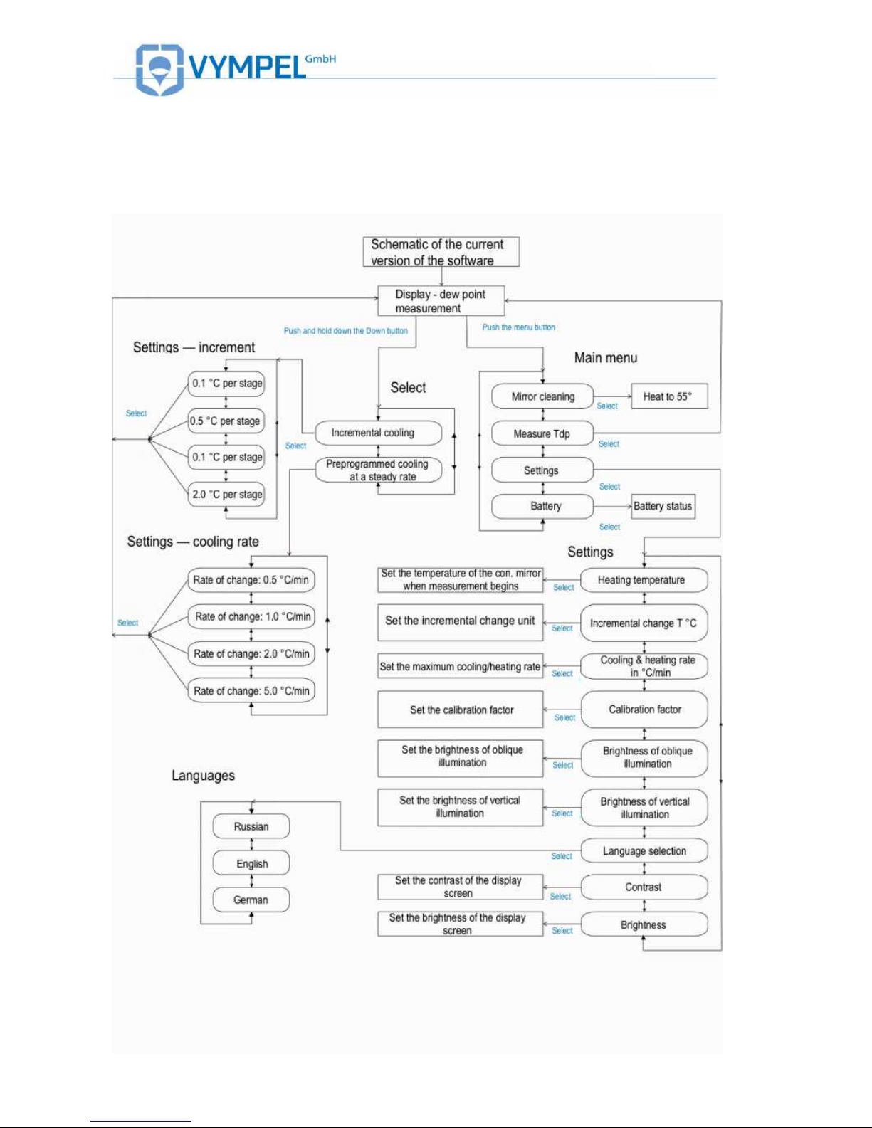
1.5 Menu of the Hygrovision mini
1.5.1 Menu structure

13
1.5.2 Main menu
Illustration 4
Briefly push the menu button to select the main menu.
The main menu consists of the analyzers main functions, which are organized
thematically under these four menu points:
• Mirror cleaning
• Dew point temperature measurement (Тdp)
• Settings
• Battery
1.5.3 “Mirror cleaning”
Illustration 5
In the “Mirror cleaning” mode, the analyzer automatically heats the surface of the condensation mirror to a predetermined temperature. This temperature will be maintained until the
cleaning program is completed. The factory preset mirror-cleaning temperature is +55 °С.
In cleaning mode, the Hygrovision mini displays the following information (illus. 5):
• Program code (M10);
• Pre-programmed mirror temperature (54.9 °C — large number in the display);
• Current housing temperature (Tb= 24.4 °C);
• Current battery charge (100%)
After the cleaning program is complete, visually inspect the condition of the mirror through
the microscope. If contaminants that could interfere with dew point measurement remain, follow the instructions for manually cleaning the mirror as described under point 5.2.
14
To leave the cleaning mode, press the menu button.
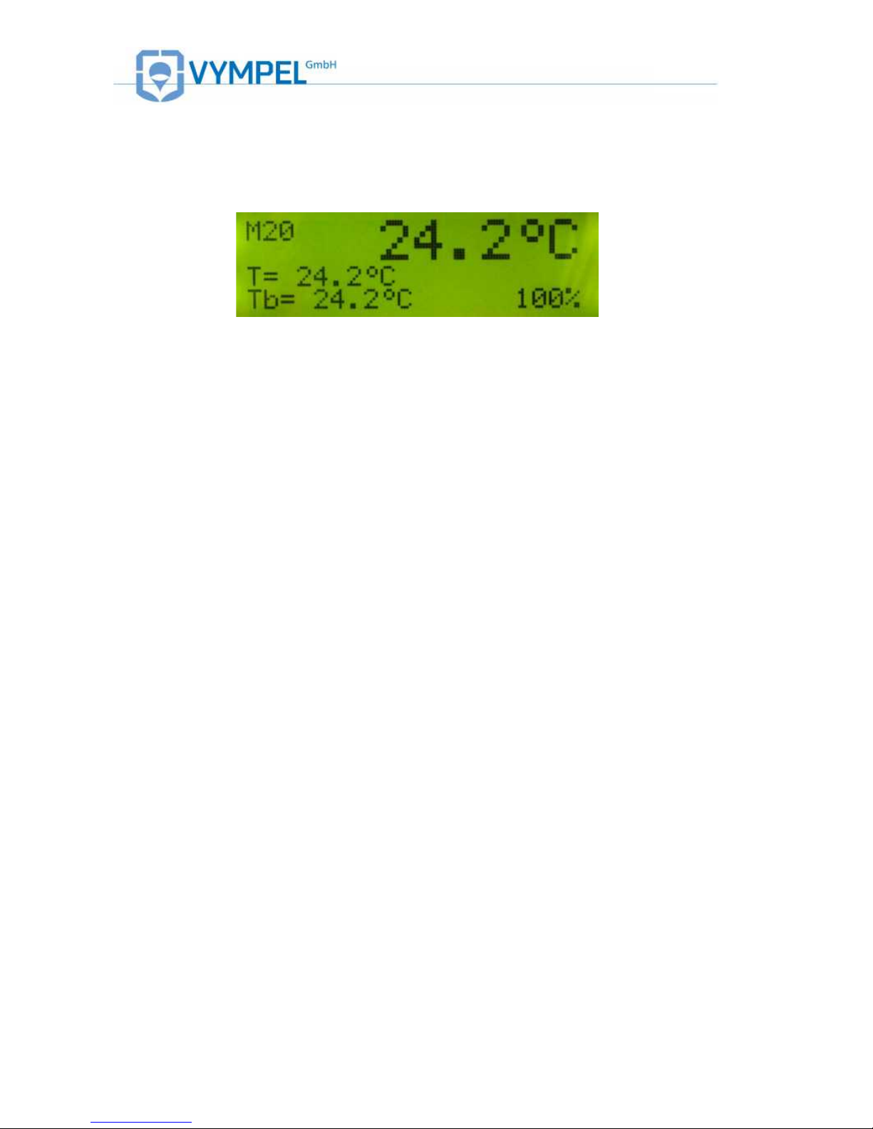
1.5.4 “Measuring the dew point: Тdp”
Illustration 6
Make sure the analyzer is turned on and select the “Dew point measurement” mode.
Use the “up” and “down” buttons to scroll through the menu points and push the “select” (yellow) button to choose the measurement mode.
When in the dew point measurement mode the analyzer will display the following information (illus. 6):
• Program code (М20);
• Current mirror temp. (24.2 °С — large number in the display);
• Pre-programmed mirror temperature: Т (24.2°С);
• Temperature of the housing Тb (24.2°С);
• Battery charge (100%)
In the dew point measurement mode, the mirror’s temperature is determined by the
temperature of the housing (Tb) and the parameter value stipulated under M31, which
specifies the “heating temperature” (see point 1.8.4).
During the dew point measurement process, the analyzer is controlled using the
select, up, and down buttons.
For specific information regarding the measurement of water and hydrocarbon dew
points, refer to points 4.2 to 4.5.
15
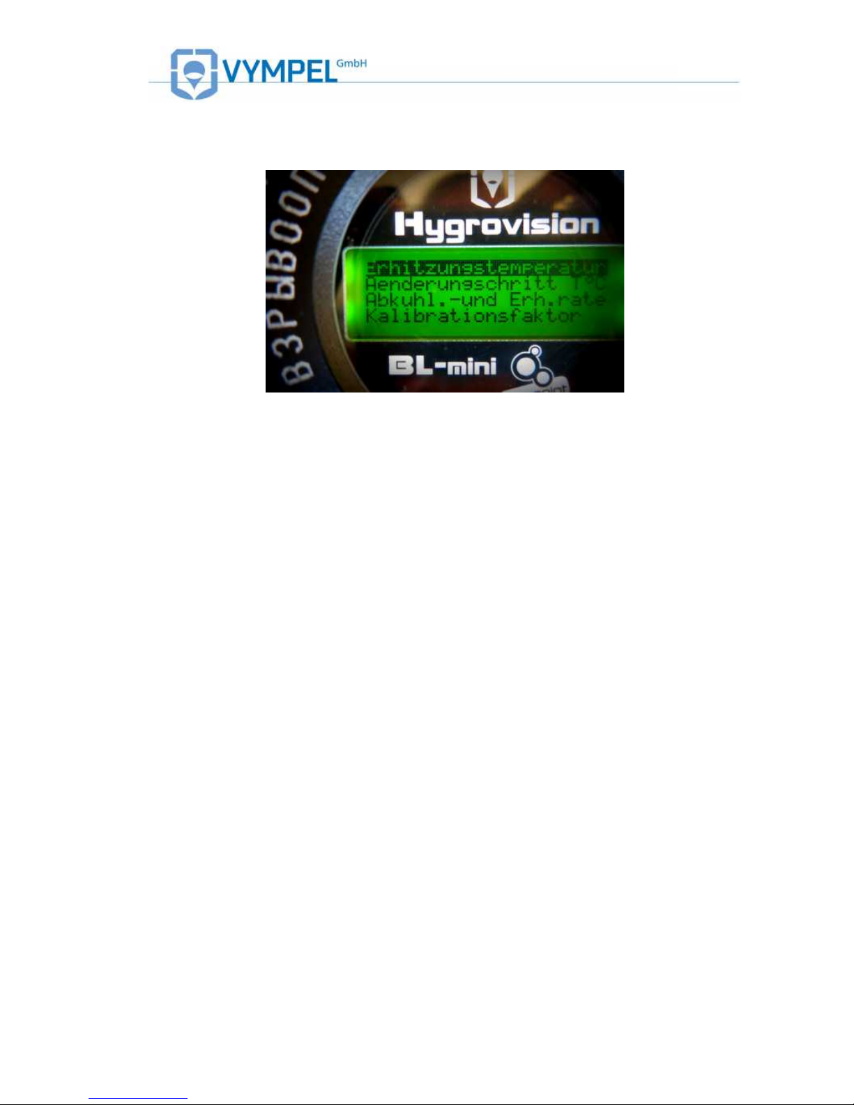
1.5.5 “Settings”
Illustration 7
The main operating parameters for the analyzers can be adjusted under the
“Settings” menu (Illustration 7). These parameters are:
• Heating temperature
• Temperature change interval for mirror cooling during the measurement cycle in
°С
• Rate of heating and cooling °C/min
• Calibration factor
• Brightness of side lighting
• Brightness of vertical lighting
• Language
• Contrast
• Display brightness
• Calibration coefficient
Use the Select (yellow) button to choose the corresponding sup-menu point.
Use the Up and Down buttons to make changes to the selected parameter.
Confirm the newly set value(s) by pushing the Select button again.
For the factory default parameter settings see Appendix C.
16
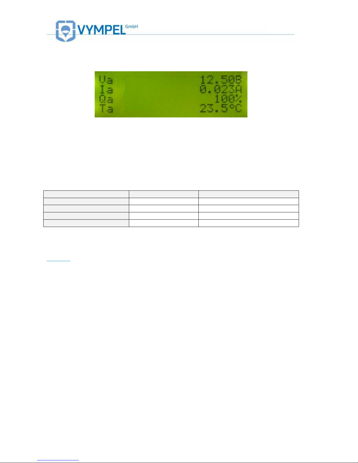
1.5.6 Status of the battery charge
Illustration 8
Under this menu, specific parameters regarding the status of the battery (IP 01) can be
viewed on the analyzer’s display (Illustration 8)
Table lists the most important parameters and the respective minimum and maximum
value tolerances.
Table 4
Parameter
Code
Value range
Voltage
Ua
9.0 – 12.6 V
Operating current
Ia
0.01 – 2.5 A
Charge status
Qa
5 – 100 %
Temperature
Ta
-20°C – + 60°C
If a battery parameter value is outside of the tolerance range listed in Table , the appropriate error message will be displayed. (See point 3.4 / Table 8).
Attention – In the first 5 seconds after this mode has been selected, the maximum op-
erating current detected during analyzer operation is determined and the voltage corresponding to this maximum power demand is displayed.

17
1.5.7 Program codes
Each of the analyzer’s program points has its own code, which is shown in the upper
left hand corner of the display.
Table 5 shows a list of these program codes.
Table 5
Code
Program point
М10
Mirror cleaning
М20
Measurement
М21
Measurement with incremental temperature change
М21М
Cooling parameters adjustment
М22
Measurement with cooling and heating rate
М23
Measurement with cooling and heating rate (when heating the mirror)
М30
Settings
М31
Heating temperature
М32
Change interval setting
М33
Maximum cooling rate setting
М34–A
Calibration factor setting A
М35
Contrast setting (side lighting)
М36
Contrast setting (vertical lighting)
М37
Language selection
М38
Display contrast setting
М39
Display illumination setting
М40
Battery
M34–B
Calibration factor setting B
18
1.6 Accessories and additional equipment
A number of accessories and additional equipment are included with delivery of the
Hygrovision mini.
A list of these items is provided under point 2.6 / Table 5.
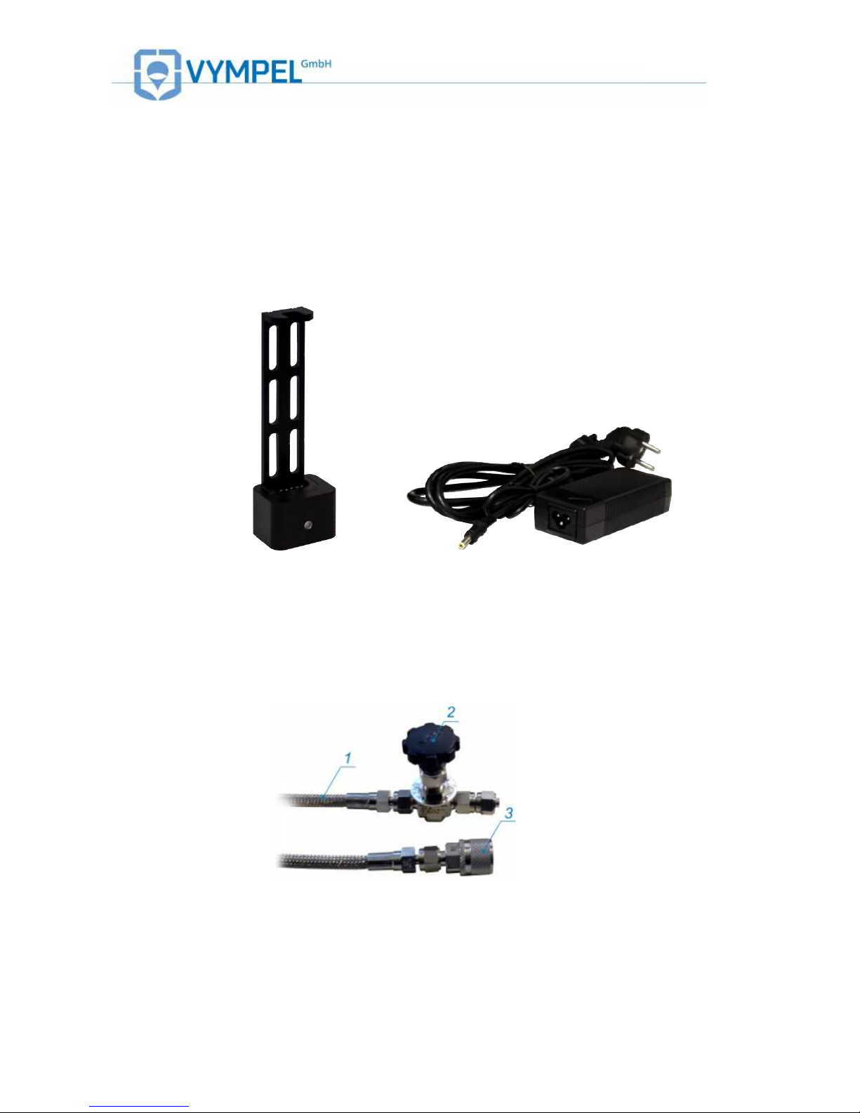
1.6.1 Battery charger
Illustration 9
In order to charge the analyzer’s battery (IP 01), a specially designed battery charger is
included with delivery. Instructions for using and handling this charger are listed on the
sticker (KRAY5.122.009EТ) that accompanies it.
1.6.2 Sample gas delivery system
Illustration 10
The sample gas delivery system included with the delivery of the Hygrovison mini consists of: a high-pressure valve (Illustration 10, Pos.2), 2.5 meters of high-pressure
hose (Illustration 10, Pos.1), and a quick-connect coupler (Illustration 10, Pos.3).
This system provides the user with a method for steadily supplying the analyzer’s
measurement chamber with sample gas.

19
1.6.3 Through-flow control system
Illustration 11
The through-flow control system consists of a fine control valve (Illustration 11,
Pos.2), manometer (Pos.3), rotameter with protective housing (Pos.5), and a quickconnect coupler (Pos.4). This system makes it possible to control and regulate the flow
of sample gas into the measurement chamber.
The system includes a 2.5-meter PVC hose to be attached to the rotameter’s outlet
nozzle for the safe release of the sample gas.
1.6.4 Particle filter
Illustration 12
Solid particulate matter with a crass-section of 15µm and larger as well as other mechanical contaminants are removed from the sample gas by means of a particle filter.
The filter cartridge (Pos.1) is inserted into the gas inlet nozzle of the gas delivery unit of
the analyzer’s housing (Pos.2).
The particle filter pre-installed when the analyzer is delivered.
Replacement filter cartridges are included with delivery as additional equipment.
For detailed instructions on replacing the particle filter refer to point 6.2.4.
The analyzer can also be operated without a particle filter.

20
1.6.5 Filter for the control of heavy hydrocarbons
Illustration 13
The filter for the control of heavy hydrocarbons is included with delivery of the analyzer.
It is intended for insertion as an additional control while measuring the dew point of water, when the sample gas contains a large quantity of glycols and heavy hydrocarbons.
The filter has a maximum operational life of 30 minutes at a flow rate of 2Nl/min.
1.6.6 Sample extraction set
In order to install a fixed sampling point, a gas sampling set can be ordered separately.
This set consists of a sample extraction module (see Appendix B) a by-pass valve, and
a membrane filter for removing liquids and particulates from the gas sample (see Appendix C.
1.6.7 Supplemental cooling system
Illustration 14
If very low dew point values (below -30 °C) are to be measured in situations where the
external temperature is high (over +35 °C) and the pressure conditions are over 70 bar,
it is recommended that supplemental cooling be used.
The supplemental cooling system is not included with delivery of the analyzer and must
be order separately. This system consists of two nozzles, and a valve for regulating the
coolant flow (see point 2.3.6).
Note: It is also possible to cool the housing of the analyzer using various liquids, such
as water or alcohol solutions.

21
1.7 Hygrovision mini set
Illustration 15
Table 6
Designation
Description
Pos.
No.
Notes
Included in Delivery
VMPL2.844.001
The «Hygrovision mini» dew point analyzer set
includes the following equipment and accessories:
1 1
KRAY3.821.003
Microscope
2 1
VMPL4.841.001
Microscope cable
3
VMPL4.161.001
Transportation case
4 1
VMPL5.122. 001
Battery charger
5 1
VMPL5.549.001
Rechargeable battery
6 1
VYMP5.183.001
Through-flow meter
7 1
VMPL6.450.001
High-pressure hose for sample gas supply (2.5 meters)
8 1
VMPL6.451.017
Filter for the of removal heavy hydrocarbons
9
KRAY4.160.001
Replacement cartridge set for the VYMP6.451.014
filter (10 replacement cartridges incl. adsorbent
medium)
10
VMPL8.392.001
Special key
11 1
PVC hose w/ inner diameter D6x1.5; Length: 2.48m
12 1
Optics cleaning solution (Eclipse 59 ml)
13 1
Cotton swabs for cleaning the sensor (50 pcs.)
14 1
Adapter (12V)
15 1

22
AC adapter (220V)
16
FE73A-15
Particle filter replacement cartridge (gas delivery system
insert)
17
DGV-2-S
Seal
18
VMPL.248.005
Sealing ring
19
Mounting connector set
DMC6M-20M15SA
Connector with external threads Dk-Lok
DMC6M-8R-SA
Connector with external threads Dk-Lok
DMC6M-8G-SA
Connector with external threads Dk-Lok
DFSA-D-6M-SA
Quick-connect coupler Dk-Lok
Operating documentation
VMPL2.844.001M
P
Testing documentation
VYMP2.844.001R
E
Operating manual
– 1
VYMP2.844.001F
O
Information form
VYMP5.122.001ET
Battery charger instruction manual
VYMP6.451.014ET
Filter instruction manual (VYMP6.451.014 filter)
Additional equipment (available by special order)*
VYMP5.549.001
Replacement battery IP-01
TH-650 DV
Stand (tripod)
VMPL5.880.006
Supplemental cooling set
FE73-15
Replacement particle filter
Accessories for installing a sample extraction point on the Pipeline
KPAY4.078.091
Gas sampling set (consists of a sampling
device (KRAY6.457.013) and a membrane
filter (KRAY6.457.022))
KPAY4.078.091-01
Gas sampling set (consists of a bypass
valve (KRAY6.451.013) and a membrane
filter (KRAY6.457.022-01))
130-502
Replacement membrane set for the
KRAY6.457.022 (-01) membrane filter
* The number of units varies depending on the order
Note: Depending on technical developments, instruments may have slight variations in
construction and delivery packaging, however these variations have no effect on the
fundamental safety and functionality of the analyzer.

23
1.8 Explosion safety provisions
The following features ensure that the Hygrovision mini is protected against explosion.
Spark arresting insulation barriers ensure the intrinsic safety of the electrical circuitry and
connections at the control buttons.
Bypass diodes and resistors ensure the intrinsic safety of the electrical circuit connected to
the control unit. These elements reduce the electrical current and voltage to the values
allowed by GOST R 52350.11 for electrical devices in Group II B. This reduction applies for
both normal and emergency operation modes. Electrical sparking is prevented through a
combination of resistors and a fuse module.
The sum of the electrical capacity and the inductivity of the electrical circuit that connects
the Hygrovision mini to external components via their individual intrinsically safe plugs
conform to the values required by GOST R 52350.11.
The electrical load does not exceed two thirds of the nominal capacity of components
ensuring intrinsic safety.
The construction and electrical properties of the LED conform to the specifications stated in
GOST R 52350.0 and GOST R 52350.1.
The maximal temperatures generated through internal heating, to which the electrical
components and the housing of the Hygrovision mini are exposed do not exceed those
allowed in GOST R 52350.0 for temperature class T5.
The connection points of the flameproof enclosure of the HV mini’s electronics unit conform
to the requirements of GOST R 523 50.1 for electrical apparatus of subgroup II B.
Lock nuts and adhesives are used to protect against the loosening of the screws, bolts, and
nuts that secure the various elements of the flameproof enclosure as well as the conductor
and grounding terminals. Similarly, locking devices are used to secure self-threading
connectors. The heads of external fixing screws are recessed and can only be accessed
using a special tool.
Cable entry points ensure that conductors have a stable and durable connection. Fasteners
comply with the requirements of the GOST R 52350.1 – 2005 directive.
The mechanical strength of the flameproof enclosure meets the requirements of GOST R
52350.0-2005 for electrical devices of Group II that are exposed to a strong risk for
mechanically inflicted damage. The surface area of the LCD display is limited to prevent
the buildup of static electricity.
Integration of electrical ports into the flameproof enclosure complies with the requirements
of GOST R 52350.0 und GOST R 52350.1.
The construction of the HV mini conforms to the general requirements of GOST R 52350.02005 for electrical equipment intended for operation in explosion-hazard areas. The seals
and connectors used for structural elements provide an IP 66 level of protection in
accordance with GOST 14254.

24
All applicable explosion protection information is displayed on the housing of the
Hygrovision mini as required by regulation.
1.9 Markings
Markings on the analyzer’s housing provide the following information:
! Trademark and name of the manufacturer
! Name of the device
! Explosion protection labeling
! Certifying Authority and Certificate Number
! Label regarding protection against the effects of solids and water according to
IEC 60529:1992 (IP54)
! Dew point measurement range
! Operating pressure limit
! Operating temperature of the device
! Serial number
! Country of manufacture
1.10 Packaging
The analyzer’s components must be appropriately protected prior to being
packaged for transportation or storage.
The device is to be packaged in a closed ventilated room with an ambient temperature of +15 °C to +40 °C and a relative humidity no higher than 80%.
The ambient air must not contain any aggressive components.
Proper packaging protects the device against the effects of climatic and mechanical stresses during loading and unloading, transportation, and storage.
The operating documentation is located under the lid of the transport case. The
packing list and accompanying certification is contained in watertight packaging
and is also located in the compartment in the lid of the case.
Illustration 16

25
2 Proper operation of the
Hygrovision mini
2.1 General requirements
2.1.1 Unpacking and visual inspection of the device
Upon delivery, please make sure that the packaging is in good condition. If it is damaged,
document this in writing and contact customer service at Vympel GmbH.
Unpack the analyzer carefully. Check that the delivery includes all of the components listed
on the accompanying inventory sheet.
Also check to make sure that neither the analyzer no any of its components has been
damaged during transportation.
Attention!
Upon receipt of a new analyzer, fully charge the battery (IP 01) of the Hygro-
vision mini before switching it on for the first time.
2.1.2 General requirements for the sample extraction site
Please observe the following criteria when selecting a site where the analyzer will be
connected to the pipeline:
! the location should offer convenient access for the mounting, installation and operation of
the analyzer
! gas samples should be collected at locations that are specially designed for this purpose
! the ambient temperature and the relative humidity should lie within the tolerance range as
listed under point 126.
2.1.3 General safety measures
In terms of protection against electrical shock, the Hygrovision mini is a Class 0I
(GOST norms 12.2.007.0 SSB) electrical device
The Hygrovision mini may not be used to take dew point measurements of aggressive
media or in an aggressive environment.
When in use, the battery charger must be connected to an electrical outlet that is
grounded (GOST norms 12.1.030 SSB).
Resistance in the ground circuit must not exceed 4 Ohms.

26
The valve of the gas sampling system must be closed and the pressure within the
sampling system must be adjusted to match ambient atmospheric pressure using the
needle valve before the analyzer is connected to or disconnected from the sample delivery pipe.
2.2 Connecting the analyzer
Place the analyzer on a level surface or affix it to a stand near the sampling point.
Ensure that the analyzer is positioned in such a way as to have adequate support.
Attach the through-flow meter (pos. 4, illus. 17) to the outflow nozzle of the measurement
chamber (pos. 5, illus 17). Ensure that the through-flow meter’s needle valve (pos.3) is closed.
Connect the PVC hose to the outlet nozzle of the rotameter (pos.1). The hose ensures
proper venting of the sample gas.
Connect the gas delivery system to the inlet nozzle of the analyzer’s measurement chamber
by means of the quick-connect coupling (pos.6). Ensure that the high-pressure valve of the
manometer is closed (pos.2).
Connections at the input and output nozzles of the analyzer are made via quick-connect
couplers that provide both a reduction in the (de)installation time and absolutely tight seals.
Please note: Gas mixtures that contain early-condensing hydrocarbons can make the visual
observation of water condensation difficult. In this situation, the filter for regulating heavy hydrocarbons (included in delivery) should be installed. The filter is installed between the highpressure hose and the gas delivery system.
Illustration 17
1- PVC hose
2- Manometer
3- Needle valve
4- Through-flow control system
5- Rotameter
6- Gas delivery system
7- Supplementary cooling system

27
2.3 Using the Hygrovision mini
2.3.1 Preparing to take dew point measurements
Switch on the Hygrovision mini portable dew point analyzer as described in the handbook above.
Slowly open the gas delivery system valve while watching the associated manometer,
in order to monitor the increase in pressure in the measurement chamber. When the
appropriate pressure is reached, open the needle valve to set the sample gas volume
flow rate of 0.5 Nl/min as indicated by the rotameter.
After the measurement chamber has been ventilated in this way for 10 minutes, reduce
the volume flow to 0.2 – 0.3 Nl/min to begin taking dew point measurements.
After the desired measuring pressure has been reached, ensure that the microscope is
optimally adjusted for observing the surface of the condensation mirror.
Use the focus ring for making fine adjustments to the sharpness of the image.
When working out of doors, the intensity of the mirror surface illumination may need to
be adjusted depending on environmental conditions and personal preferences.
After adjusting the illumination intensity and image sharpness, select the “Dew point
measurement” mode.
Attention!
When measuring the dew point of flammable gases, the
measurement chamber and the sampling connection hose must
be ventilated for 10 – 20 minutes before connecting the analyzer
to the power supply.
When doing maintenance and servicing work on the Hygrovision
mini, the analyzer should always be disconnected from the electrical
supply.
Upon completion of maintenance and servicing work, the
measurement chamber and the gas sampling connection
should be ventilated for 10 – 20 minutes before putting
the analyzer back into operation.

28
2.3.2 Visual identification of water condensation
Illustration 18 Illustration 19
When using the Hygrovision mini, the operator can observe the condensation of water
vapor utilizing either side lighting or vertical lighting.
Under side lighting, the dark surface of the mirror appears to become evenly covered
with red spots as condensation forms (illustration 18).
Under vertical lighting, the light surface of the mirror appears to become evenly
covered with dark spots as condensation forms (illustration 19)
Illustration 20 Illustration 21
In the temperature range between 0 °C and -10 °C, it may occasionally happen
that condensed water vapor on the mirror surface itself, is in a super-cooled
state for a certain period of time.
In the temperature range from -10°C to -50°C, when condensation occurs it can
form on the mirror’s surface in both a liquid and crystalline state simultaneously
(illustrations 20 and 21). In this situation the dew point is also the freezing point.

29
Illustration 22
Illustration 23
Under side lighting, the ice crystals that form appear as clear luminous red patches
when viewed through the microscope (illustration 22).
Under vertical lighting, the ice crystals that form appear as branching dark patches on
a light background when viewed through the microscope (illustration 23).
2.3.3 Visual identification of hydrocarbon
condensation
The condensation of hydrocarbons (HCs) can only be observed under vertical lighting.
In contrast to the observation of the condensation of water vapor, the condensation of
hydrocarbons cannot be observed under side lighting. When illuminated from the side
the surface of the mirror simply remains dark during hydrocar
bon condensation in
the "HC Dew Point” mode (illustration 25).
Illustration 24
Hydrocarbons that condense onto the mirror’s surface appear as a film of rainbow-colored gradients (illustration 20), These hydrocarbons range up to include
heptanes.
As the mirror continues to cool, this rainbow-colored film becomes colorless and
spreads out to cover the entire surface of the mirror.

30
Illustration 25
Illustration 26
Octane and higher hydrocarbons condense on the surface of the mirror in the form of
small, dilute dark spots. As the mirror continues to cool, these small spots slowly form
into droplets (illustration 26).
As the cooling process continues, the small condensation droplets slowly collect to
more completely cover the mirror’s surface, until it becomes noticeably darkened. Finally, larger colorless drops form on a rainbow-colored background (illustration 24).

31
2.3.4 Rough dew point measurement
Rough dew point measurements serve to establish the temperature range within which
the dew point is to be found. Rough dew point measurements are made exclusively using the incremental cooling process (manual mode).
To change the cooling parameter settings select the menu point “Cooling parameters”
" “Change interval”. Each time the “Dew point measurement” mode is started, the
value set for the change interval under the “Cooling parameters” menu will be used for
the measurement process.
The factory default setting for the change interval in the rough dew point measurement
program is 5 °C. This value can be changed as desired.
The size of the cooling interval is key to the accuracy of the rough measurement being
taken.
The size of the absolute error is directly influenced by the choices made in setting the
change interval parameters. For a change interval of 5 °C, the absolute error for the
measurement being taken is ± 2.5 °C.
Please carry out the preliminary dew point measurements according the process outlined in illustration 23.

32
Illustration 27

33
When the device is first switched on, all temperatures shown on the display (mirror
condensation temperature; housing temperature and target temperature) may vary by
up to ± 0.2 °C. The value for the condensation mirror temperature is determined by the
sum of the housing temperature value and the heating/cooling temperature value.
Illustration 28
By using the “down” button, the target temperature can be adjusted to a colder value.
The current temperature of the condensation mirror should reach this value within a
few seconds.
After the Down button is pushed once, a timer appears in the display showing the time
that is passing as the mirror changes to the temperature that has been entered. Each
time the Up or Down button is pushed the timer restarts.
2.3.5 Measuring water and hydrocarbon
dew points
After taking a rough dew point measurement, hold down the Up button for several seconds to select the normal dew point measurement mode.
A menu will appear on the display that offers the choice of either incremental cooling
(illustration 29) or automatic cooling (illustration 30) modes.
Illustration 29 Illustration 30
Please note: incremental cooling set to a temperature interval of 2 °C or automatic
cooling (at a rate of 1 °C per minute) will guarantee a water or hydrocarbon dew point
measurement with an accuracy ±1 °C.
A diagram of the dew point measurement process carried out in the incremental cooling mode is shown in illustration 32.
A diagram of the dew point measurement process carried out in the automatic cooling

34
mode is shown in illustration 31.
When taking water dew point measurements in automatic cooling mode, push the
Down button to fix the temperature at which condensation occurs, and to fix the temperature at which evaporation occurs push the Up button.
The dew point value will be calculated as the mean of these two temperatures (the
condensation and evaporation points) in automatic cooling mode and shown on the
analyzer’s display.
When measuring the dew point of hydrocarbons in automatic cooling mode fix the
condensation temperature as described above. However, unlike when measuring the
dew point for water, no evaporation temperature is registered for hydrocarbons. Instead
to establish the dew point of hydrocarbons push the Up button twice after fixing the
condensation temperature.
In incremental cooling mode the condensation and evaporation temperatures are not
automatically saved.
In order to calculate the dew point temperature of water and/or hydrocarbons in this
mode, use the following formula:
DP
Water
= (Т
C (W)
+ ТV)/2
DP
Hydrocarbons
= Т
C (HC)
Т
C
=
Fixed temperature value of the condensation of
water vapor (W) or hydrocarbon vapor (HC)
Т
V
=
Fixed temperature value of the evaporation of
the water condensate
DP
Hydrocarbons
=
Hydrocarbon dew point temperature
DP
Water
=
Water dew point temperature
Recommendations for determining the duration of the temperature stages in incremental cooling mode can be found under point 4.3.1 (Rough dew point measurements).
In the event that traces of condensate remain on the mirror’s surface after the dew
point measurement procedure has been completed, select the Mirror cleaning mode.

35
Illustration 31

36
Illustration 32

37
2.3.6 Supplemental cooling
Illustration 24
The graph in illustration 29 shows the effectiveness of the supplemental cooling system. The analyzer’s integrated cooling system is directly influenced by the housing
temperature, which in turn is directly influenced by the ambient temperature. In addition, the process of cooling the condensation mirror raises the temperature of the analyzer’s housing by 5 to 7 °C. In some situations, in order to take measurements at very
low temperatures (≤ -50°C) it may be necessary to lower the temperature of the housing by means of supplemental cooling.
A variety of media can be used to cool the housing (water; propane; natural gas, etc.)
The housing has built-in cooling channels that provide for the easy and reliable circulation of liquid and gas as cooling media. The inlet and outlet ports are designed to accept pipe connectors with G1/8 external threads.
The cooling system can withstand pressures of up to 100 bar.
The measurement of very low temperature dew point values under very high operating
pressure requires the introduction of supplemental cooling of the analyzer’s housing.
Please note: The analyzer’s housing temperature (T
housing
/ Tb) must always remain
at least 5 °C above the dew point temperature being measured throughout the supplemental cooling process.
To connect supplemental cooling, remove the caps from the analyzer housing
(Illustration 1, Pos. 7); (Illustration2; Pos.12). Attach the socket DMC3M-2G-NTA SA
(Illustration 34; Pos. 3) to the inlet opening of the cooling channel as well as the hose
connection adapter DHAM 10M-AG-S (Illustration; 34; Pos 5) to the outlet opening.
Connect the hose (Illustration 34; Pos. 1) with flow-line adapter (Illustration; Pos 4) with
the inlet socket (Illustration 34;Pos. 3). To connect the hose to the refrigerant bottle use
!75,0&
!70,0&
!65,0&
!60,0&
!55,0&
!50,0&
!45,0&
!40,0&
!35,0&
0& 5& 10& 15& 20& 25& 30& 35& 40&
Lowest possible T
(mirror)
°C
Housing temperature °C
9.0&MPa&
2.7&Mpa&
0.1&MPa&
33

38
fitting DMC 6M-14M15-SA; DMC 6M-16M15-SA or DMC 6M-18M15-SA (included with
the supplemental cooling accessories).
If necessary, connect a ventilation hose to the connection adapter DHAM 10M-AGS(Item 5) in order to properly vent used gas.
Water or natural gas may also be used as supplemental coolant media.
Illustration34
2.4 Deinstallation of the Hygrovision mini
Use the following procedure to uninstall the analyzer:
1) Switch off the analyzer;
2) Close the high pressure valve of the gas delivery system;
3) Using the needle valve integrated into the through-flow control system, adjust the
pressure in the measurement chamber to match that of the ambient environment;
4) Disconnect the sample gas delivery system and the through-flow control system from
the measurement chamber.

39
3 Maintenance
Analyzer maintenance consists of regular metrological recalibration, checks of the technical
condition and, if necessary, cleaning the condensation mirror and replacing filter elements.
Proper storage, transport, and operational conditions will ensure that the analyzer’s
metrological characteristics continue to conform to the relevant prescribed standards.
3.1 Function tests
When the analyzer is switched on, the following function tests should be carried out:
! Charge status and condition of the battery pack (IP-01)
! Condition of the condensation mirror
! Functionality of the thermoelectric battery
! Status of the lighting system
3.1.1 Check the status of the battery charge
Select “Battery” mode (see point 1.5.6). If the battery (IP-01) is in proper working order, values for parameters displayed will lie within the tolerances listed in Table
If the charge status is below 20%, fully charge the battery. Please, only use the charging unit
delivered with the analyzer the charge the IP-01 battery pack.
The charging unit can use either 220V AC current or 12V DC current to charge the battery.
The battery charging procedure is also illustrated on the sticker (VMPL5.122.001ET ) that is
delivered with the charging unit.
Attention!
The battery (IP-01) should only be (re)charged in an explosion-proof
area. The battery should only be charged using the charging unit delivered with the analyzer!

40
3.1.2 Check the condensation mirror
Perform a visual inspection of the state of the surface of the condensation mirror using
the microscope. Be sure to adjust the focus if necessary.
The condition of a clean condensation mirror surface may differ slightly from the illustrations in Appendix D. These differences are due to the heterogeneity of the mirror’s
dielectric material and the mechanical processing of the condensation surface. It may
therefore be the case that a few red dots or scratches are observed under side lighting
during this check.
Should three fourths of the surface of the mirror be covered with red dots, it will be necessary
to clean the condensation mirror (see point 3.2.2).
3.1.3 Check that the thermoelectric battery – TEB
(Peltier element) is functioning
In dew point “Measurement" mode, press the "down" function key (Illustration 3; Pos. 4)
several times to adjust the temperature of the mirror to between -15 °C and -25 °C. The
“current temperature” of the condensation mirror should not take more than 30 seconds in
order to reach the “input temperature”. This process can be monitored on the display using
the timer.
Now select "Mirror cleaning" mode. The “current temperature” of the condensation mirror
should level off at +55 °C (±0.2 °C) within a minute.
If all the above steps carried out without problems - it can be assumed that the
thermoelectric element is fully functional.
If no problems arise when carrying out the above steps, it can be assumed that the
thermoelectric element is fully functional.
3.1.4 Check the lighting systems
After the analyzer is first switched on (see 1.4.4), it takes two to three seconds for the
operating system to load. The version of the installed OS is displayed on the analyzer’s
LCD screen. When this initial start-up process is complete, the analyzer automatically
switches to measurement mode.
The vertical lighting system is activated during this initial process. Once the OS is
loaded and the analyzer switches to the dew point measurement mode, mirror illumination switches from vertical lighting to side lighting.
In Appendix D, example images of the mirror’s surface under both side and vertical
lighting are shown. These pictures show a clean mirror as well as several different
types of condensate accumulation.
Use the “select” button to switch between lighting modes.
Should the sequence described here proceed as outlined, it can be assumed that the
lighting systems are functioning normally.
Lighting intensity can be adjusted under the “Settings” menu (see point 1.5.5).

41
3.1.5 Perform a leak test
After the device is installed, all gas-sample line connections must be examined for
leaks in the following manner:
• Close the valve of the flow control system
• slowly open the inlet valve of the sampling line and the valve at the inlet of the ana-
lyzer’s measuring chamber
• Apply a soap emulsion to the connection points between the gas supply system, the
measuring chamber and the flow control system; making sure to completely coat over
the space between the lock nuts and the connecting sleeves
If bubbles form in the emulsion it is an indication that there is a leak. If this occurs, it is
necessary to reseal the leaky connection connection and retest it.
3.2 Maintenance procedures
Standard maintenance includes:
! Service the power supply unit (battery)
! Check the condition of the condensation mirror and clean if necessary
! Check the efficiency of mirror cooling (efficiency of the thermoelectric battery)
! Replace the particle filter
! Calibrate the analyzer
! Clear error messages
3.2.1 Servicing the power supply unit IP-01
Observing the following guidelines will ensure that the battery has a long service life:
• If the analyzer is not used for more than ten days, remove the battery to avoid
unnecessary discharging.
• The charge status of all batteries held in storage should be checked at least once
a month and when necessary fully recharged.
3.2.2 Cleaning the condensation mirror
In order to check the condition of the condensation mirror’s surface, set the analyzer to
“Mirror cleaning” mode.
If contamination that could interfere with water and/or hydrocarbon dew point measurements remains on the surface of the mirror after the automatic cleaning process is
completed, the following steps can be taken before manually cleaning the mirror.
1. Select the “Dew Point Measurement” mode.
2. In the incremental cooling mode, press the “down” button repeatedly to lower
the target temperature to between -25 °C and -30 °C.

42
3. After reaching the desired target temperature select “Mirror cleaning” mode
again.
Repeat this process up to three times if necessary.
If there is no improvement in the condition of the mirror’s surface after repeated cycles
in the “Mirror cleaning” mode, it will be necessary to clean the mirror manually.
Everything required for this procedure is included with delivery.
Attention!
Manual cleaning of the condensation mirror is only to be done in an
explosion proof environment!
Please follow these steps when cleaning the mirror manually :
1. Disconnect the illumination cable and remove the microscope.
2. Remove the eight bolts from the measurement chamber and open it. (This
should only be done in a “clean” environment).
3. Dip one of the cotton-swab applicators into the cleaning fluid and gently clean
the surface of the condensation mirror. An absolute minimum of pressure
should be applied to the mirror’s surface during this procedure (illustration 35).
Illustration 35
In certain cases the condensation mirror can alternatively be given a “quick” cleaning.

43
Using the special key provided (VYMP 8.392001), turn the sleeve containing the integrated observation window counter-clockwise and remove it from the gas delivery sys-
tem (illustration 36). Clean the surface of the condensation mirror with an applicator
dipped in the cleaning fluid (illustration 37).
Illustration 36 Illustration 37
Please note: If after cleaning the mirror in the manner described above
contaminants remain on the surface of the mirror, it can also be cleaned using acetone in place of the cleaning fluid delivered with the analyzer.
3.2.3 Checking the efficiency of the
thermoelectric battery (TEB)
Follow these steps to check the thermoelectric battery:
1. Switch on the analyzer;
2. Select the dew point “Measurement” mode and press the “down” button repeatedly to set the temperature T to -60 °C (±1);
3. After three minutes have passed, note the mirror temperature T and the housing temperature T
b
shown on the display. The difference between these two
values must not exceed 65 °C;
4. Select the “Mirror cleaning” mode.
Attention!
Please take the utmost care when cleaning the condensation mirror
manually as damage in the form of scratches or grooves will greatly reduce the performance of the analyzer. Mechanical damage to the condensation mirror caused during cleaning is not covered under the warranty.

44
3.2.4 Replacement of the particle filter
Illustration 38
Optimally, the particle filter cartridge should be replaced at least once a year.
To replace the filter cartridge (illustration 38):
1. Unscrew the inlet nozzle (Pos. 1) and remove it from the sample delivery
unit of the analyzer’s housing
2. Carefully remove the small spring (Pos. 2)
3. Carefully remove the filter cartridge (Pos. 3)
4. Place a new cartridge in the opening (Pos. 4)
5. Carefully replace the spring
6. Screw the inlet nozzle back into the sample delivery unit of the housing
3.2.5 Calibrating the Hygrovision mini
Calibration of the Hygrovision mini involves shifting the analyzer’s standard calibration curve to reflect a set value within the analyzer’s measurement range.
To make the adjustment, reset the calibration factors in the “Settings” mode:
⇒ Under the “Settings” menu, use the Up and Down buttons to select the calibration co-
efficient mode.
⇒ Set the coefficient to the desired value using the Up and Down buttons.
⇒ Press the Select button to confirm the set value.
The value for the calibration coefficient A is calculated as follows:
Т
calib
= A + B * Т
meas
Т
calib
= defined dew point value
Т
meas
= measured dew point value
Т
calib
; Т
meas
– Dew point temperature measured directly using a reference analyzer.
Calibration factor A is determined as Т
calib
= 0°C and calibration factor B =1.

45
3.3 Troubleshooting malfunctions
Possible technical failures as well as the appropriate responses in each case are presented
in Table 7.
Table 7
Failure
Possible cause
Response options
1.
The analyzer won’t switch
on.
The battery charge is too low.
(Re)charge the battery.
a) The battery temperature exceeds tolerable limits
(0 °C – + 45°C).
b) The electrical circuit between
the thermometer and the temperature control unit is defective.
2.
The battery cannot be
(re)charged: the
charging indicator is red.
c) There is no electrical contact
between the battery and the
charging unit.
Check the
appropriate parameters
and elements.
a) The lighting cable electrical circuit is defective.
Check the lighting cable
3.
The lighting for the optical
system is not functioning.
b) The light emitting diode is
defective.
Replace the cable with
the LED.
a) The microscope is not
properly installed.
Ensure that the microscope is properly aligned
and screwed into position
until it is tight.
b) The observation window
lens is dirty.
4.
The sharpness of the
mirror’s image can’t
be adjusted.
c) Condensation has accumulated
in the space between the
observation window and the lens
of the microscope.
Clean the optical
elements using the
cleaning fluid included in
the set for cleaning the
mirror.
a) The thermoelectric battery
is defective.
Replace the
thermoelectric battery.
5.
The mirror does
not reach the set
temperature.
b) The through-flow volume
in the measurement chamber is
too high.
Reduce the through-flow
volume in the measurement chamber to 0.5
Nl/min.

46
c) High operating pressure
or housing temperature
(see point 4,5)
Use supplemental cooling of the analyzer housing
a) From time to time the
analyzer switches off unexpectedly.
6.
b) Led indicator flickers.
The battery is not
properly (securely)
installed.
Ensure that the battery lid
is aligned correctly and
screw it down tight.
3.4 Error message codes
Table 8 presents a list of error codes and their meanings as well as a description of the
appropriate action to take in each case.
Table 8
Error mes-
sage
Diagnostic error message
Response
E 01
Poor battery contact!
Replace the battery!
Check the battery contacts; if necessary replace
the battery.
E 02
T
bat
≥ + 60.1 °C
Cool the battery!
In order for the analyzer to regain functionality,
allow the battery to cool down.
E 03
T
bat
≤ – 20.1°C.
Warm the battery!
In order for the analyzer to regain functionality,
allow the battery to warm up.
E 09
Circuit breaker tripped!
Cooler!
E 10
Circuit breaker tripped!
Requires + 5V.
E 11
Circuit breaker tripped Ia over 2500
mA
Switch the device off and then turn it on again. If
the same error message is displayed contact the
manufacturer.
E 12
Battery is low!
Charge battery!
Recharge the battery.
E 13
Tb ≤ – 45,1 °C!
Warm the device
E 14
Tb ≥ + 65,1 °C!
Cool the device
In order to regain functionality, heat/cool the analyzer so that it is within the temperature range
listed in Table 3.
If your analyzer displays an error code not listed in this table, please contact the
manufacturer.

47
4 Markings
Labeling on the analyzer’s housing provides the following information:
! Trademark and name of the manufacturer
! Name of the device
! Explosion protection labeling
! Certifying Authority and Certificate Number
! Information label about protection against the effects of solids and water according to
IEC 60529:1992 (IP54)
! Dew point measurement range
! Operating pressure limit
! Operating temperature of the device
! Serial number
! Country of manufacture
5 Packaging
The analyzer’s components must be appropriately protected prior to being packaged
for transportation or storage.
The device is to be packaged in a closed ventilated room with an ambient temperature
of +15 °C to +40 °C and a relative humidity of no more than 80%.
The ambient air must not contain any aggressive components.
Proper packaging protects the analyzer against climatic influences and mechanical
stress during (un)loading, transportation, and storage.
Operating documentation is located under the lid of the transport case, as are the packing list and accompanying certification. These are protected by watertight packaging.
6 Storage
Analyzers are to be stored exclusively in containers intended for that purpose supplied by the
manufacturer. These containers are designed to protect the device from mechanical damage, contamination and the effects of aggressive media.
For transportation purposes, analyzers may be held in storage (max. 6 months) in the transport packaging.

48
7 Transportation
Transportation requirements:
Analyzers are to be transported only in climate-controlled, hermetically sealed closed
containers.
When in service, the device must be transported in the carrying case included with delivery.
8 Recycling
The materials and work pieces used in the manufacture of the Hygrovision mini dew
point analyzer are environmentally friendly. During the period the device is in service as
well as after it has been decommissioned, these materials and work pieces can be
classified as non-hazardous to human health. Likewise they present no risk to production and storage spaces.
Hygrovision mini analyzers that are no longer being used may be disposed of in any
way deemed appropriate by the user.
Old disused batteries are to be turned over to companies that are licensed and/or
authorized to dispose of these products.

49
Anlage А
Factory settings
Table 9
Code
Parameter
Unit of
measurement
Measurement
range
Value
M 31
Warming temperature
°C
0 – 60
0.0
M 32
Change interval
°C
0 – 10
5.0
M 33
Cooling rate
°C / min
0 – 10
3.0
M 34
Calibration factor
°C
-10 – 10
0.0
M 35
Oblique illumination brightness
-preset level-
0 – 10
10
M 36
Vertical illumination brightness
-preset level-
0 – 10
5
M 37
Language selection
-
Russian
English
German
Russian
M 38
Display: contrast
-preset level-
0 – 10
6
M 39
Display: brightness
-preset level-
0 – 10
8
M34-B
Calibration coefficient
°C
-10 – +10
0,0

50
Appendix B
Sample extraction system
Illustration 39
The sample extraction system is intended for permanent installation on the main
gas line. This apparatus makes possible the extraction of a gas sample at the existing working pressure.
The sample extraction system is mounted onto the pipe by means of an installation
bushing (Illustration 39, pos. 1) attached to the gas line at the desired sampling
point. The installation bushing is made of 09G2C steel (9MnSi5/ 13Mn6) and is included with delivery of the extraction system.
Gas flow can be controlled or stopped by opening or closing the integrated ball valve. When the valve handle is in the vertical position (parallel to the gas flow) the
valve is open and gas flows into the extraction apparatus. When the handle is in the
horizontal position (perpendicular to the gas flow), the valve is closed and gas is
prevented from entering the sampling system.
The connection nozzles of the sample extraction system is intended to be connected to a pipe made of stainless (DK-Lok, THT-3R60-12-1). No additional rolling
of the pipe end is necessary in order to affix the pipe.

51
Appendix C
Membrane Filter (KRAY6.457.022)
Function
The membrane filter is designed to remove from the gas sample the liquids and particulate matter that could contaminate or damage the analyzer’s measuring chamber or
the components of the sampling unit.
Description
The filter consists of a housing and a membrane.
The filter housing has an inlet opening labeled B and an outlet opening labeled OUT.
(See schematic drawing KRAY4.078.091-01: A [Inlet opening], B [Purge], OUT [outlet
opening]). The gas sample enters the filter housing through the inlet port, passes
through the membrane, and exits through the outlet port. In this process small contaminants and even micro particles are trapped by the membrane and removed from
the gas sample.
Membrane
Illustration 40
The membrane has microscopic pores through which gas and water vapor molecules
can easily pass. Liquids, on the other hand, are comprised of a large number of molecules that are closely bound together. The surface tension inherent in liquids is very
strong. Due to this surface tension bonding, liquid molecules remain too large to pass
through the microscopic pores of the membrane. In this way even the smallest aerosols
and particles are removed from the gas stream (Illustration 40). And because all of the
gas-phase molecules can easily pass through the filter, the gaseous composition of the
sample remains unaltered. The membrane is extremely elastic and is appropriate for
use where a wide range of technological fluids may be present. The low adsorption
properties of the membrane mean that this filter is also appropriate for systems intended to have component concentration levels in the ppm or ppb range. The membrane is also constructed of a robust but soft and flexible material in order to ensure a
long service life.

52
Technical Data
Maximum operating pressure
250 bar
Recommended maximum gas flow volume through
the membrane: 130-502
72,000 cm3 / min
Gas flow volume through the membrane: 130-502
14,400 cm3 / min
Housing material / sealing ring material
Stainless steel / Viton
KRAY6.457.022
Dimensions (mm):
KRAY6.457.022-01
see Illustration 30
see Illustration 31
KRAY6.457.022
(inlet, outlet)
Outer diameter ø12.0 mm
Connection:
KRAY6.457.022-01
(inlet, outlet, purge)
Outer diameter ø 6.0 mm
Illustration 41
Illustration 42
Recommended installation and usage
The filter is available in two versions:
Version 1 – for mounting directly onto the sample extraction device
Version 2 – for installation within a sample delivery system

53
Illustration 43
For version 1, the filter is mounted in such a way that liquids seperated from the gas stream return
to the sample source. In this configuration (
Illustration 43) the filter is mounted vertically, immediately downstream of the
sample extraction point (Pos.2). The gas then flows through the OUT port toward the analyzer.
Illustration 44
Version 2 of the filter is also mounted vertically as shown in Illustration 33.
Pos.1
Filter
A
Sample gas inlet
B
Bypass outlet / purge
OUT
Outlet to analyzer
A minimum flow rate of 5 Nl/min is required to purge the filter through outlet B.
Ordering information:
Filter part number is KRAY6.457.022:
Replacement Membrane Set (5 pieces)

54
Anlage D
Examples of the appearance of
water and hydrocarbon condensation
(Microscope perspective)
Condensation mirror as seen
under side lighting
Condensation mirror as seen
under vertical lighting
Illustration 45
Absence of
condensation
(individual red dots and
scratches are acceptable)
Illustration 46
Illustration 47
Condensation mirror
showing water con-
densation
Illustration 48

55
Illustration
49
Water condensation in both
liquid and crystaline phases
Illustration 50
Illustration 51
Water condensation in
crystaline phase only
Illustration 52
Illustration 53
Hydrocarbon condensation
(inc. heptane)
Illustration 54

56
Illustration 55
Hydrocarbon condensation
(Octane and
higher ranked HCs)
Illustration 56

57
Appendix E
Illustration 57

58
Appendix F
Page:
No.
Adjusted
Replaced
New
Cancelled
Number of
documents
Document
number:
Signature
Date

59
 Loading...