

Precision | Economy | Safety
Operating Manual
Hygrovision BL
Dew point analyzer
www.vympel.de

!
!"#$"%&'&()*+,-./.,#&01&'&234567899::;3 <&
"!
!"#$%&'(&)'*!%*!+&
,-! .%*%/"$&0%+)/12!1'*& 3!
,-,-! 24/2'+%&"*0&(1%$0&'(&"22$1)"!1'*& 3!
"#$"%&'! (!
)*'+,!%)!-""+*.-/*%0! (!
/1"'&!%)!*0&/-++-/*%0&! (!
*0&/-++-/*%0!-0,!%"'$-/*02!$'3#*$'4'0/&! (!
,-5-! %62$'+1'*&2/'!%)!1'*& 7!
,-8-! 9%"+4/%9%*!&2/1*)12$%& ,:!
,-;-! "*"$<=%/&)'*+!/4)!1'*& ,5!
5-//'$1!"-.6! 78!
,->-! "*"$<=%/&2'?%/&+422$<& ,8!
,-@-! "001!1'*"$&)'92'*%*!+&"*0&"))%++'/1%+& ,;!
4*.$%&.%"'! 79!
2:;!<=>?!@!A:;!BCD;;ECD!F>GHC>=!;I;HDJ!K4>LD=!MM7N! 79!
2-&!,'+*O'$1!&1&/'4! ! 4%,'+!MM7! 7P!
"-$/*.+'!)*+/'$! 7P!
2+1.%+&!-0,!Q'-O1!Q1,$%.-$5%0&!)*+/'$! 7P!
'R/'$0-+!"%S'$!&#""+1!.-5+'! 7T!
*$!-,-"/'$! 7T!
&#""+'4'0/-+!.%%+*02!&1&/'4! 7(!
/$*"%,! 7(!
&-4"+'!2-&!'R/$-./*%0!&1&/'4! 7(!
Q*2QU"$'&&#$'! ! O'0/*02!4%,#+'! 7V!
2-&!"$'"-$-/*%0!&1&/'4! ! &2-UMM8! 7V!
,-3-! )'*!/'$&"*0&01+2$"<&%$%9%*!+& 5:!
,-A-! !B%&"*"$<=%/C+&9%*4& 5:!
/#$0*02!%0!/Q'!-0-+1W'$! XM!
,*&"+-1',!*0)%$4-/*%0! XX!
"$%"'$/*'&! XX!
-0-+1W'$!.Q'.6! XY!
-#/%4-/*.!,'S!"%*0/!4'-&#$'4'0/!4%,'! XY!
/#$0*02!%))!/Q'!-0-+1W'$! X9!
,-7-! )'**%)!1*.& & 2%/12B%/"$&0%D1)%+& 5@!
,-,:-! +2%)1(1)"!1'*+& 5A!
,-,,-! B<./'D1+1'*&#$&+!"*0"/0&%E4129%*!& 8:!
,-,5-! %62$'+1'*&+"(%!<&2/'D1+1'*+& 85!
5-! +"(%&'2%/"!1'*&'(&!B%&B<./'D1+1'*&#$& 8;!
5-,-! .%*%/"$&+"(%!<&9%"+4/%+& 8;!
5-5-! %62$'+1'*F+"(%&1*+!"$$"!1'*&"*0&'2%/"!1'*& 8;!
8-! 2/%2"/1*.&!B%&"*"$<=%/& & ('/&'2%/"!1'*& 8@!
8-,-! .%*%/"$&/%E41/%9%*!+& 8@!
#0"-.6*02!-0,!O*&#-+!*0&"'./*%0! 8P!

!
!"#$"%&'&()*+,-./.,#&01&'&234567899::;3<&
#!
%"'$-/*02!$'&/$*./*%0&! 8P!
"$'"-$*02!/Q'!$'.Q-$2'-5+'!5-//'$1!)%$!-0-+1W'$!%"'$-/*%0! 8P!
&-4"+'!'R/$-./*%0! 8T!
8-5-! )'**%)!1*.&!B%&"*"$<=%/& 83!
/'&/*02!&'-+!*0/'2$*/1! 8(!
8-8-! (4*)!1'*"$&!%+!& 87!
&S*/.Q*02!%0!/Q'!-0-+1W'$! 8V!
.Q'.6*02!/Q'!4*.$%&.%"'!+*2Q/*02! 8V!
.Q'.6*02!/Q'!.%0,'0&-/*%0!4*$$%$!-0,!/Q'!/Q'$4%'+'./$*.!5-//'$1! YM!
,-/'!-0,!/*4'! YM!
5-//'$1!"-.6!.Q-$2'!&/-/#&! YM!
&S*/.Q*02!%))!/Q'!-0-+1W'$! YM!
;-! '2%/"!1*.&!B%&B<./'D1+1'*&#$& ;,!
;-,-! 2/%)"4!1'*"/<&9%"+4/%+& ;,!
;-5-! B"*0$1*.&!B%&B<./'D1+1'*&#$& ;,!
"$'"-$*02!/%!/-6'!4'-&#$'4'0/&! Y7!
Q'-/*02!/Q'!.%0,'0&-/*%0!4*$$%$! YX!
.+'-0*02!/Q'!4*$$%$! YX!
-,Z#&/*02!/Q'!+*2Q/*02!*0/'0&*/1! YX!
4*$$%$!&.-0!@! Y8!
&.-00*02!4%,'! Y8!
/-6*02!,'S!"%*0/!4'-&#$'4'0/&! YY!
;-8-! B)&0%?&2'1*!&9%"+4/%9%*!&4+1*.&!B%&2/%2/'./"99%0&/"!%&'(&)''$1*.&G&B%"!1*.&!B%&
)'*0%*+"!1'*&91//'/& ;>!
;-;-! B)&0%?&2'1*!&9%"+4/%9%*!&)''$1*.&!B%&91//'/&+!%2&#<&+!%2& ;@!
;->-! ?"!%/&0%?&2'1*!&9%"+4/%9%*!&4+1*.&!B%&2/%2/'./"99%0&/"!%&'(&)''$1*.&G&B%"!1*.&!B%&
)'*0%*+"!1'*&91//'/& ;3!
;-@-! ?"!%/&0%?&2'1*!&9%"+4/%9%*!&)''$1*.&!B%&91//'/&+!%2&#<&+!%2& ;A!
;-3-! B)&0%?&2'1*!&9%"+4/%9%*!&1*&"4!'9"!1)&9'0%& ;7!
;-A-! ?"!%/&0%?&2'1*!&9%"+4/%9%*!&1*&"4!'9"!1)&9'0%& >:!
;-7-! +2%)1"$&)'*+10%/"!1'*+&?B%*&9%"+4/1*.&0%?&2'1*!&"!&D%/<&$ '?&!%92%/"!4/%+& >5!
4'-&#$*02!,'S!"%*0/!-/!O'$1!+%S!/'4"'$-/#$'&! 9X!
&#""+'4'0/-+!.%%+*02!&1&/'4! 98!
*0&/-++-/*%0!%)!/Q'!&#""+'4'0/-+!.%%+*02!&1&/'4! 9Y!
#&*02!/Q'!&#""+'4'0/-+!.%%+*02!&1&/'4! 9Y!
;-,:-! 4*1*+!"$$1*.&!B%&B<./'D1+1'*&#$& >@!
#0*0&/-++*02!/Q'!-0-+1W'$! 9P!
>-! !%)B*1)"$&9"1*!%*"*)%& >3!
>-,-! .%*%/"$&1*+!/4)!1'*+& >3!
>-5-! 9"1*!%*"*)%&2/')%04/%+& >3!
4-*0/'0-0.'!%)!/Q'!"%S'$!&#""+1!#0*/! 9T!
.+'-0*02!/Q'!.%0,'0&-/*%0!4*$$%$! 9(!
.+'-0*02!/Q'!.%0,'0&-/*%0!4*$$%$! PM!
/'&/*02!/Q'!/Q'$4%'+'./$*.!5-//'$1!K/'5N! PX!

!
!"#$"%&'&()*+,-./.,#&01&'&234567899::;3 <&
$!
.-+*5$-/*02!)%$!Q1,$%.-$5%0&! PX!
>-8-! $1+!&'(&2'++1#$%&%//'/&9%++".%+& @8!
@-! 9"/H1*.+& @>!
3-! 2")H".1*.& @>!
A-! +!'/".%& @@!
7-! !/"*+2'/!& @3!
/$-0&"%$/!.%0,*/*%0&! PT!
,:-! 0%)'991++1'*1*.&"*&0&01+2'+"$& @3!
,,-! "22%*016&I& @A!
,,-,-! B<./'D1+1'*F#$&"*"$<=%/J&9"1*&)'92' * % * !+& @A!
,5-! "22%*016&#& 3:!
,5-,-! B<./'D1+1'*F#$&%62$'+1'*&2/'!% ) ! 1 ' *& 3:!
,8-! "22%*016&)& 35!
,8-,-! ($'?&)'*!/'$&+<+!%9&9'0%$F::,&D<92>-,A8-::,-& 35!
,;-! "22%*016&0& 38!
,;-,-! ."+&0%$1D%/<&+<+!%9&9'0%$F::,&D<92$@-;>:-::,-& 38!
,>-! "22%*016&%& 3>!
,>-,-! )''$1*.&9'04$%&D<92>-AA:-::8-& 3>!
)'*+!/4)!1'*&0/"?1*.& 3>!
,@-! "22%*016&(& 33!
,@-,-! 2/%++4/%&/%04)!1'*&9'04$%&D92$5-A;A-::>-& 33!
,3-! "22%*016&.& 37!
,3-,-! B1.BF2/%++4/%&."+&/%$%"+%&9'04$%& 37!
,A-! "22%*016&B& A,!
,A-,-! %$%)!/1)"$&2"/"9%!%/+&'(&!B%&B<./'D1+1'*&#$C+&2$4.+& A,!
,7-! "22%*016&1& A5!
,7-,-! +%!!1*.+&9%*4& A5!
4'0#!,'&.$*"/*%0! (X!
*0,*O*,#-+!)#0./*%0!"-$-4'/'$!4'0#&! (Y!
5:-! "22%*016&K& A3!

!
!"#$"%&'&()*+,-./.,#&01&'&234567899::;3<&
%!
5:-,-! !B%&9'0#4+&/%.1+!%/& A3!
5,-! "22%*016&H& A7!
5,-,-! 4*1D%/+"$&!%/91*"$&2/'./"9J&B<./'D1+1'*-%6%& A7!
55-! "22%*016&$& 7;!
55-,-! 0%+)/12!1'*&'(&!B%&)"$1#/"!1'*&2/')%04/%&('/&B<0/')"/#'*+& 7;!
58-& 7@!
58-! "22%*016&9& 7@!
58-,-! %6"92$%+&'(&B)&"*0&?&)'*0%*+"!1'*& 7@!
5;-! "22%*016&*& 77!
5;-,-! 0')49%*!"!1'*&)B"/!& 77!

!
!"#$"%&'&()*+,-./.,#&01&'&234567899::;3 <&
&!
–
VYMPEL GmbH
Bahnstraße 17
40212 Düsseldorf
Deutschland
Tel: +49211 210 77 391
Fax: +49211 210 77 399
email: info@vympel.de
www.vympel.de
–
Responsible for manufacturing:
143530, Russia, Mossbauer Area, Istrinsky District,
Dedowsk, Shkolny Passage, No.11
Tel.: 8 (495) 992-38-60 (ext. 219)
Fax: 8 (495) 992-38-60 (ext.217)
e-mail: vympelm100@aha.ru
Internet: www.npovympel.ru

!
!"#$"%&'&()*+,-./.,#&01&'&234567899::;3<&
'!
1. GENERAL DESCRIPTION
1.1. PURPOSE AND FIELD OF
APPLICATION
This manual provides a description of the construction and function of the Hygrovision BL dew point analyzer, model number
KRAY2.844.007 (also called HV BL, Hygrovision, device, instrument, and analyzer in the text).
The Hygrovision BL is a compact portable analyzer used to establish the dew point temperature of water and hydrocarbons.
This portable hygrometer (hereinafter analyzer) functions according to the principal of direct measurement. It employs a
temperature-controlled mirror upon which condensation forms to
establish dew point.
The Hygrovision is one of a series of revolutionary new highprecision chilled-mirror analyzers that are characterized by the
inclusion of a supplemental visualization system. This system
makes it possible to physically observe the condensation (dew
point) process. In addition, this system has two different illumination options, which makes it possible to easily distinguish between water condensation and the formation of hydrocarbon
condensates.

!
!"#$"%&'&()*+,-./.,#&01&'&234567899::;3 <&
(!
PURPOSE
FIELD OF APPLICATION
TYPES OF INSTALLATIONS
The analyzer is designed to measure the dew point of water
(hereinafter also: W dew point, WDP, dpW) and the dew point of
hydrocarbons (hereinafter also HC dew point, HCDP, dpHC) in
natural gas and other gaseous media at operating pressures. It
is also intended for the visual monitoring of the condensation
process.
Hygrovision BL dew point analyzer are designed to be used for:
Spot checking in the field
Checking the functionality of permanently installed dew point
analyzers
Corroborating the accuracy of the measurements made by permanently installed units
Regular direct measurement of water and carbohydrate dew
points in locations that are not equipped with automatic throughflow analyzers are where such analyzers cannot be installed
Checking the results of various manufacturing and working
processes (such as the drying and vacuuming of equipment and
systems, damp presses, processes involving the use of steam,
regeneration, evacuation, etc.)
The BL can be employed by a variety of sectors, including the
gas, oil, and chemical industries, metallurgy, the power industry,
equipment manufacturing, and many other branches where the
quality of manufacturing and operating process can be evaluated through the control of water and hydrocarbon dew points.
INSTALLATION AND OPERATING
REQUIREMENTS
Only by qualified personnel may carry out the installation and
maintenance of the analyzer.
Operating personnel must be familiar with the requirements and
instructions contained in this manual and must be trained in the
operation of explosion-protected equipment.
It is strongly recommended that this training be provided by the
Vympel company.
!
!"#$"%&'&()*+,-./.,#&01&'&234567899::;3<&
)!
1.2. EXPLOSION PROTECTION
The analyzer consists of an electronics module and a measurement module. (see point 1.4).
The electronics module conforms to all of the requirements for
explosion-protected equipment in accordance with GOST R
52350.0-2005. The explosion Protection categories "flameproof
enclosure (d)" according to GOST R 52350.1-2005 and "Intrinsically safe circuit (i)“ according to GOST R 52350.11-2005
identify the instrument as safe for use in explosion hazard zones
both inside closed facilities and outside in the field according to
GOST R 52350.14-2006.
Electronic Components of the HV BL
Ex protection markings
Electronics module
1 Ex d[ib] IIA T5 Х
Electrical devices associated with the electronics
module (thermoelectric battery, temperature sensor, photo diodes)
These are located with the flameproof enclosure and therefore do not have Ex protection
Light diode
As a simple electrical apparatus according to
GOST R 52350.11 it has no Ex protection
markings.
Attention!
To ensure that the Hygrovision BL is safe with regard to explosions, it is important to
regularly purge the analyzer with air and to always fill the measurement chamber with
sample gas before switching the device on.
!
!"#$"%&'&()*+,-./.,#&01&'&234567899::;3 <&
*+!
=11>?@34@=AB& & CD&@,E"%&+FG+"HE., #
=11>?@34@=AB& & 6D&I%F"#&J.++, +&/$ +G "HF &$#KF+&
/.KF&%.*LE.#*&
=11>?@34@=AB& & MD&I%F"#&J.++, +&/$ +G "H F &$# K F+ &
J.H+,/H,NF&O-F+E.H"%P&%.*LE.#*&
=11>?@34@=AB& & 9D&?H"EEF+.#*&,G&%.*L E&+" )/ &K$ F &
E,&Q"EF+&H,#KF#/"E.,#&
1.3. MEASUREMENT PRINCIPLE
The Hygrovision BL is a compact, portable analyzer used for taking automatic and manual measurements of the dew point temperature of water and/or hydrocarbons.
This portable chilled-mirror automatic hygrometer operates according to the principle of direct measurement and employs a
temperature-controlled mirror to establish the dew point. During
the measurement process the reflectivity of the mirror is measured. As the temperature of the mirror is lowered, its reflectivity
begins to go down when the dew point is reached and condensation begins to form. In this process condensates are deposited on
the mirror (reflective surface).
A special system uses optical properties to register the formation
of this condensate film.
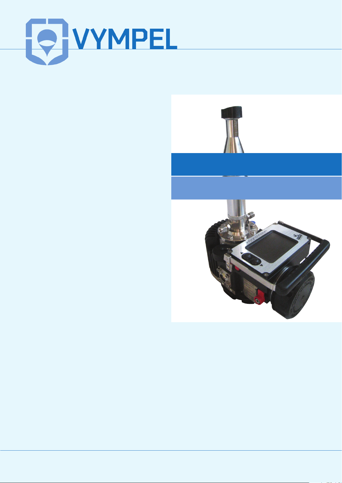
This system utilizes the phenomenon of total refraction to register
dew point.
A laser emitting vertically polarized light illuminates the interface
of a heterogeneous media (gas) 1 and a reflective dielectric surface (temperature controlled mirror) 2 at a specific angle. This
angle is known as Brewster’s Angle.
When the dew point mirror (dielectric surface) is clean, in other
words, when no condensate has formed, the polarized light rays
falling on the interface between the gas and the mirror’s surface
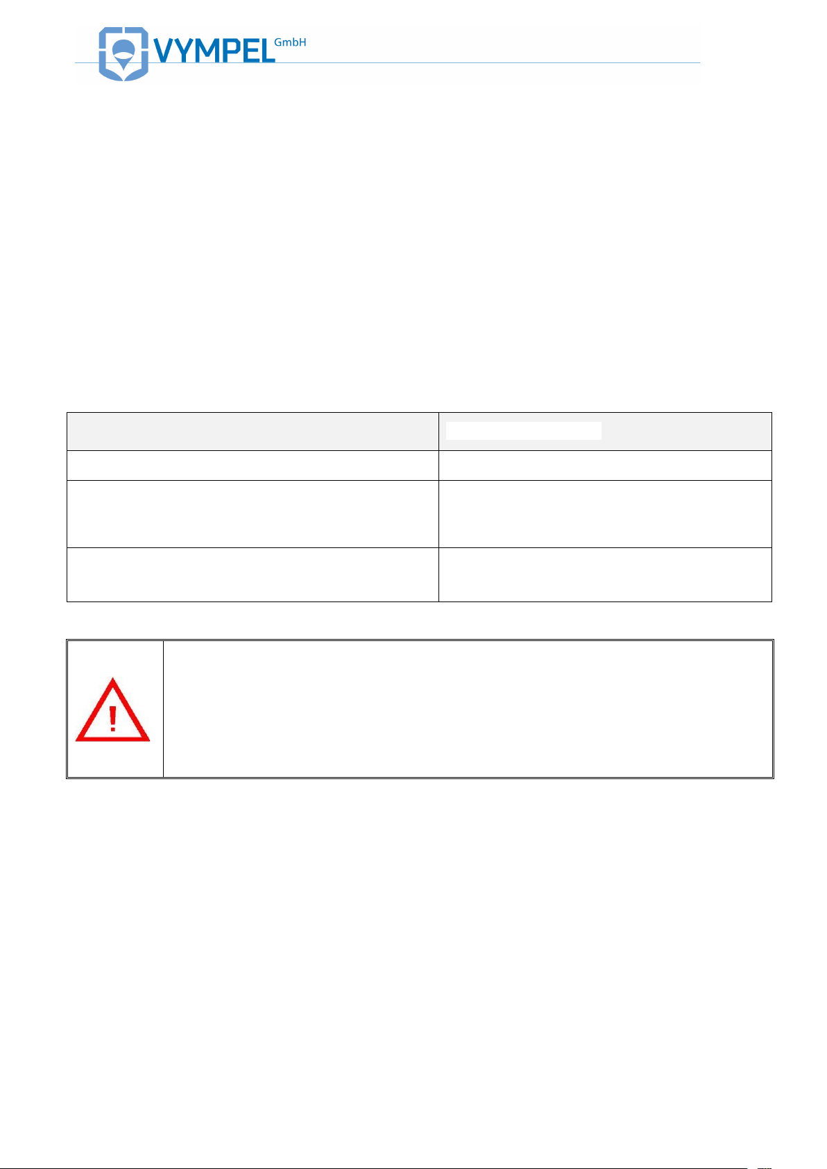
are completely refracted. As a result no light is reflected onto either of the photo detectors (F1 and F2). This results in a null signal from the sensors (ILLUSTRATION 1). With the microscope
attached, total refraction can be observed visually under both side
lighting and vertical lighting. Under side lighting*, the surface of
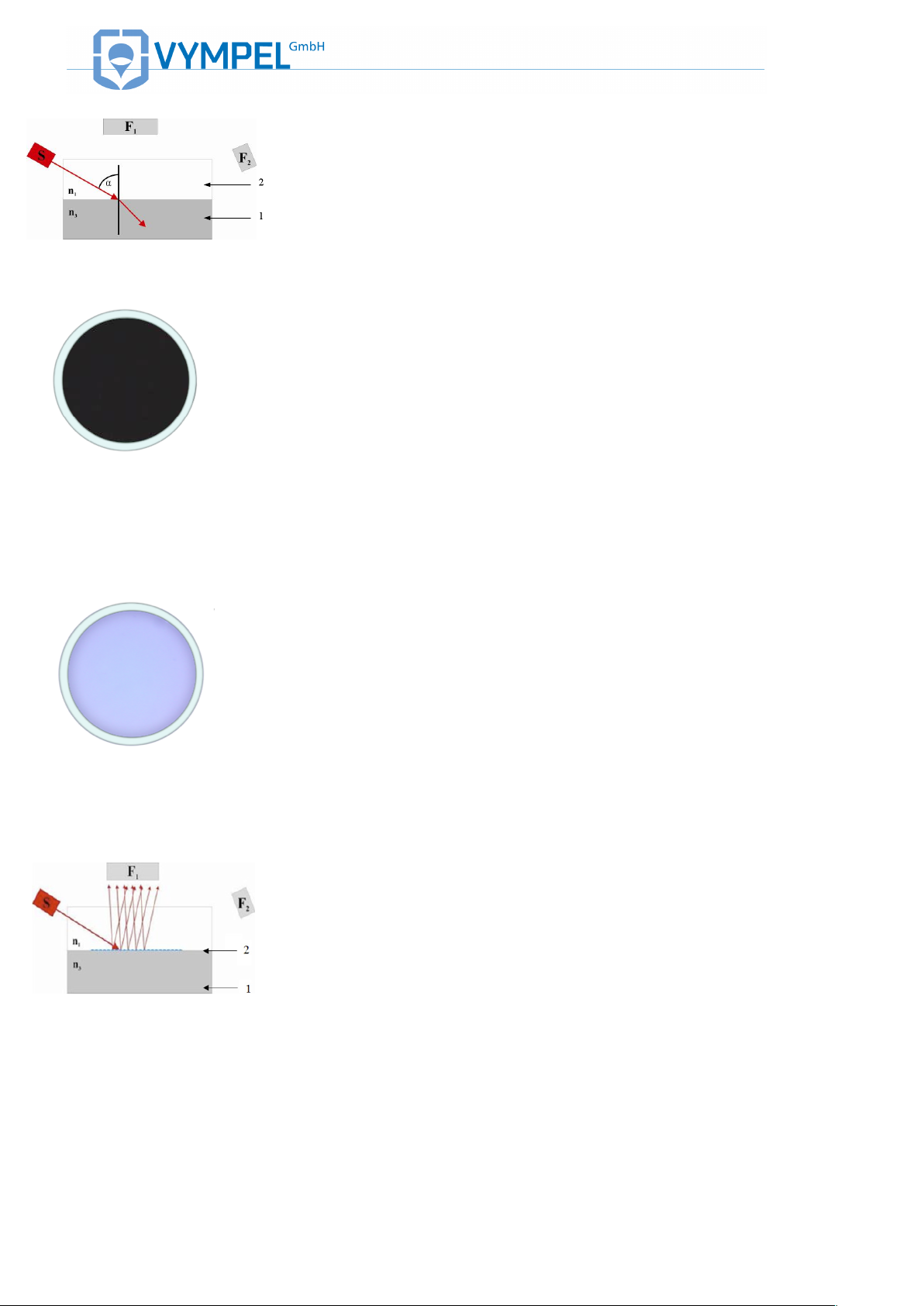
the dielectric mirror appears black (illustration 2). Under microscope (vertical) lighting the mirror’s surface appears light blue
(ILLUSTRATION 3).
*Please note: the side-lighting unit and the laser are not the same
component.
In the case of water vapor, as the temperature of the mirror is
lowered and condensation droplets begin to form, the angle at
which the polarized light strikes the surface changes with the result that refraction no longer occurs. Instead, the light rays are
reflected and scattered. The photoelectric registration system records an increase in the intensity of the light detected by the
photo detector located in position F1 (ILLUSTRATION 4). The
signal intensity (aka signal level) is dependent on the amount of
water condensation.
Under side lighting, water condensation appears in the form of an
accumulation of luminous, somewhat similarly sized red droplets
!
!"#$"%&'&()*+,-./.,#&01&'&234567899::;3<&
**!
=11>?@34@=AB& & RD&S&H,#KF# /" E., #&" /&/F F # &
$#KF+&/.KF&%.*LE.#*&
=11>?@34@=AB& & TD&S&H,#KF# /" E., #&" /&/F F # &
$#KF+&-F+E.H"%&%.*LE.#*&
=11>?@34@=AB& & ;D&1.*LE&+")&K.GG+"HE .,# &"# K&
+FG%FHE.,#&K$F&E,&(I&H,#KF#/"E.,#&
=11>?@34@=AB& & 8D&(I&H,#KF# /" E., #&O.#H %$ KU
.#*&LFNE"#F/P&
in the middle of the mirror’s surface (ILLUSTRATION 5). Under
vertical lighting this condensation appears as an accumulation of
little round black spots evenly distributed over the entire surface
of the condensation mirror (ILLUSTRATION 6).
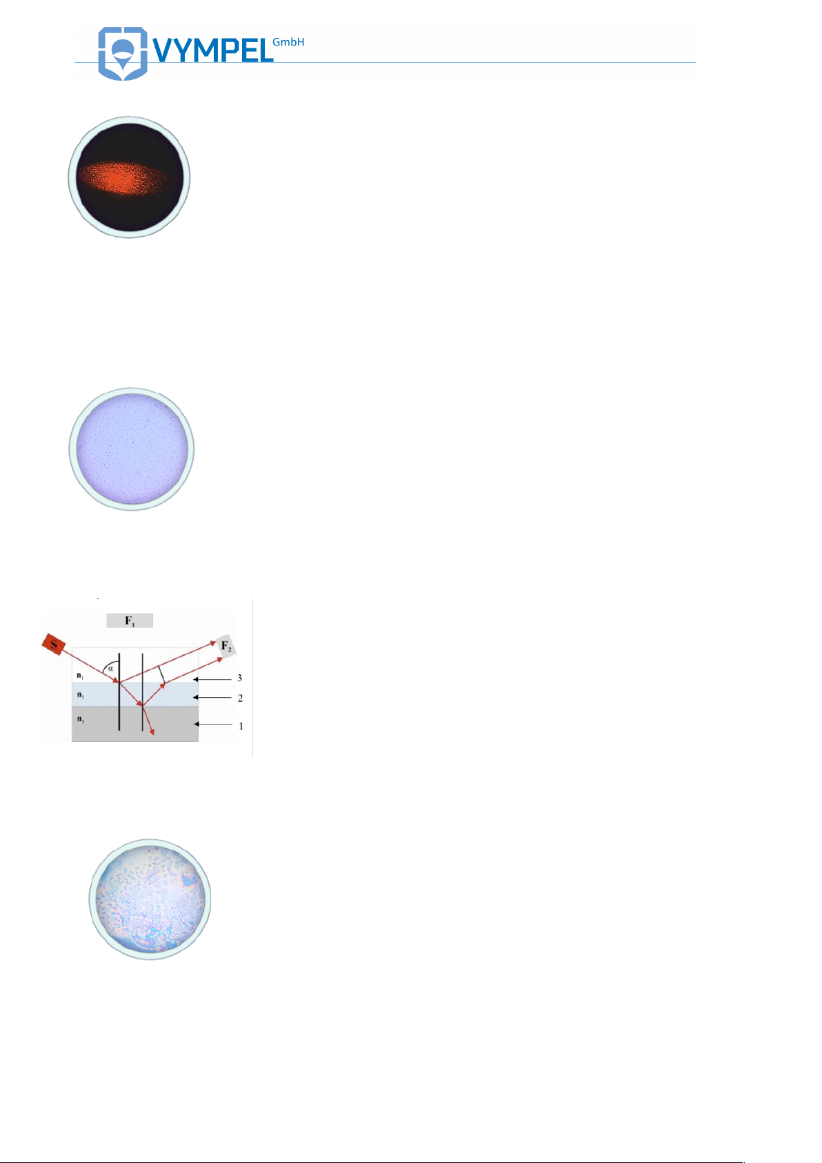
In the case of hydrocarbons, precipitated condensates accumulate in the form of a thin film on the surface of the mirror (Illustration 7). The building of a contiguous condensate layer (2) on the
mirrors surface (1) results in a change in the angle at which the
polarized light strikes the surface of the dielectric mirror.
The beam of light emitted by the laser is partially reflected as it
encounters the gas/condensate interface (3/2). This set of light
rays is then registered by the photo detector at position F2.
At the same time, due to the condensate film’s high degree of
transparency, a set of slightly refracted light rays, passes through
the gas/condensate interface and is reflected as it strikes the
condensate/mirror interface (2/1). These light rays are then also
registered by the photo detector at position F2. This second set of
rays is now slightly out of phase with the first set.
As a result, the registration system records two distinct light signals detected by the F2 sensor. These two light signals create an
interference pattern due to the slight phase difference.
The intensity of the light signal detected by the sensor is directly
dependent on the quantity of hydrocarbon condensates in the
condensation film.
The hydrocarbon condensation process can only be observed
visually under vertical illumination. In contrast to water vapor condensation, the process of HC condensation cannot be made visible under side lighting, so even though the sidelight is activated,
the mirror remains dark (ILLUSTRATION 2).
Hydrocarbons up to and including Heptanes form rainbow colored
spots. These spread out until they link up to form one continuous
thin iridescent film. (ILLUSTRATION 8). If the mirror continues
to be cooled further, this thin iridescent film becomes a colorless
plastic layer covering the entire condensation mirror’s surface.
Octane and heavier hydrocarbons condense onto the mirror in
the form of small dark semi-transparent dots. With further cooling,
these dots grow to become small droplets and spots
(ILLUSTRATION 9).
Continuation of the cooling process causes these small droplets
to continue to grow, eventually forming large colorless drops of
condensate on an iridescent background.
For further images of water and hydrocarbon condensation refer
to Appendix N.
!
!"#$"%&'&()*+,-./.,#&01&'&234567899::;3 <&
*"!
=11>?@34@=AB& & VD&(I&H,#KF# /" E., #&O, HE "# F &
"#K&LF"-.F+P&
1.4. ANALYZER CONSTRUCTION
The analyzer’s cold-body housing (see ILLUSTRATION 10 and
ILLUSTRATION 11) consists of the high-pressure chamber (1)
a sample sized receptacle (hereafter in the text the measurement
cell (2)) a removable visualization system with 40 power magnification (hereafter in the text microscope (16) and an electronic
module with an integrated touch screen display (10). The analyzer’s high-pressure chamber is designed for a working pressure
of up to 300 bar, and serves to supply and remove the sample
gas that passes over the condensation mirror. In order to observe
the condensation process, the high-pressure chamber is fitted
with a small window upon which the visualization system can be
mounted.
The microscope is mounted directly onto the Hygrovision’s highpressure chamber.
The electronic module controls the analyzer’s processes (cooling/heating); records the mirror temperature and regulates the
photoelectric registration system.
The Hygrovision BL is operated by means of control buttons and
the touch screen display.
Recorded dew point values can be downloaded by means of an
IR port and an RS 485 interface.
In order for the analyzer to operate independent of an external
power supply, a slot for a storage battery is integrated into the
Hygrovision‘s housing, as is a socket for connecting the unit to an
external power supply (12–32V, 15W).
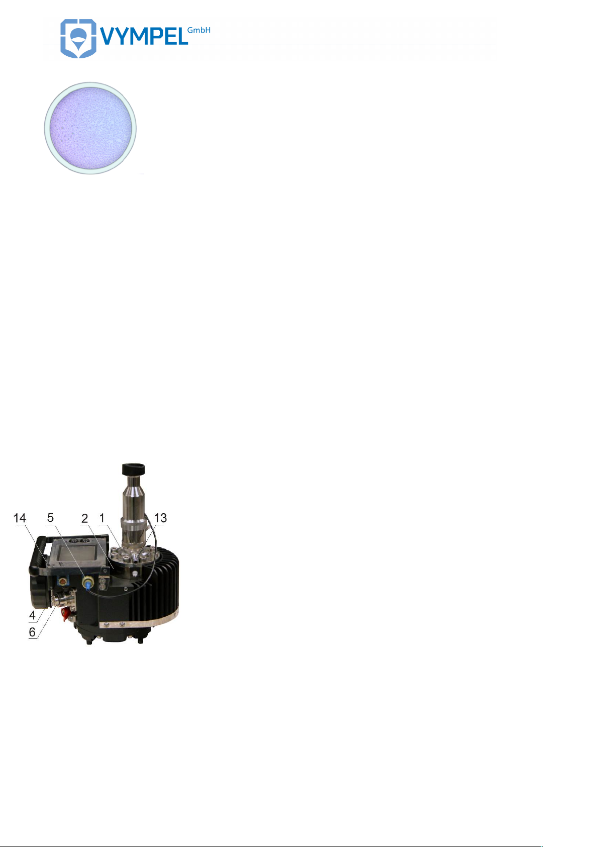
=11>?@34@=AB& & C:D&!".#&H,JN, #F # E/&, G&EL F & &
()*+,-./.,#&01&OCP&
Main components
(see ILLUSTRATION 10 and ILLUSTRATION 11)
• Gas delivery block (Pos.1);
• Measurement cell (PIP) (Pos.2);
• Battery compartment cap (Pos.3);
• Connection for the pressure sensor (Pos.4);
• Plug connector for the light emitting diode (Pos.5);
• RS 485 Modbus interface (Pos.6);
• Ventilation channel for supplementary cooling (Pos.7);
• IR port (Pos.8);
• On/off button (Pos.9)
• Touch screen (Pos.10);
• Control buttons (Pos.11);
• Sample gas inlet nozzle (Pos.12);
• Sample gas outlet nozzle (Pos.13);
• Stylus for use with the touch screen (Pos.14);
• Battery cap securing device (Pos.15).
!
!"#$"%&'&()*+,-./.,#&01&'&234567899::;3<&
*#!
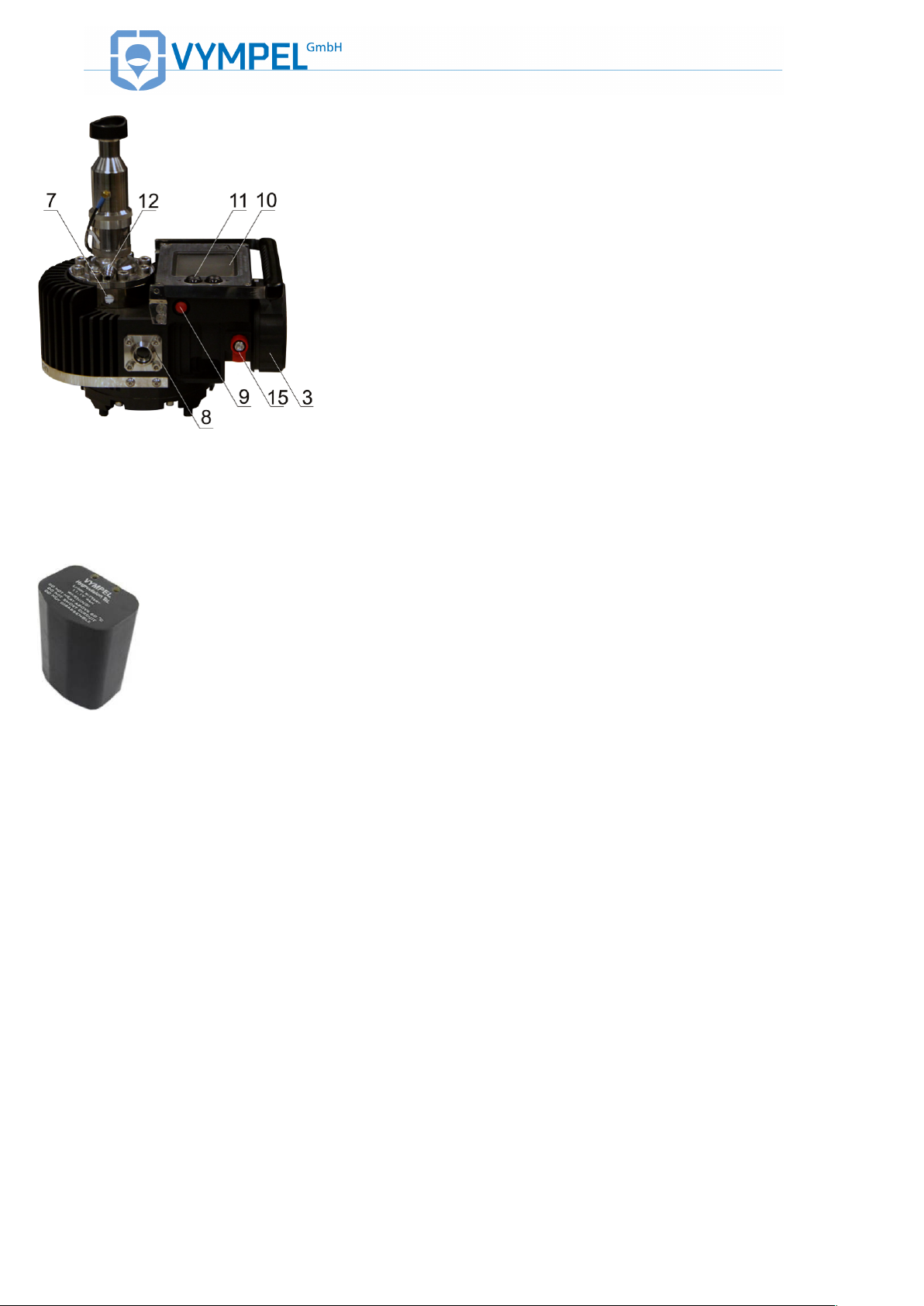
=11>?@34@=AB& & CCD&!".#&H,JN, #F # E/&, G&EL F & &
()*+,-./.,#&01&O6P&
The measurement cell, the electronic module with integrated touch
screen and the power supply module (storage battery) are enclosed within the analyzer’s metal housing (see Appendix A). The
housing is made up of three chambers.
Two of the three chambers (chambers 1 and 2) are pressure resistant encapsulations. These chambers house the circuit boards for
the electronic module (chamber 1) and the storage battery (chamber 2). The connection points for the external power supply and the
IR data port are located on the side of chamber 1.
The third chamber (chamber 3) houses all of the electronic module’s control and display elements. The touch screen display is integrated into the top of chamber 3. Connection points for an external pressure sensor and the microscope’s side-lighting element are
located on the side of this chamber. All of the electrical circuits
housed in chamber three meet the requirements for intrinsic safety.
BATTERY PACK
=11>?@34@=AB& & C6D&3FHL"+*F"W %F&W "EEF +)&
N"HX&
1.5. ANALYZER POWER SUPPLY
Hygrovision series analyzers have an independent onboard power
supply, the BP-06 power supply unit (hereinafter also referred to as
the rechargeable battery, battery, BP)
Important technical data for the BP:
Battery type
LIR18650 (Li-Ion);
Number of elements
6
Rated voltage
11.1 V
Max. discharge current
≤ 3 А
Electrical capacity
4 А h
Service life
300 recharging cycles
(max. 2 years)
Operating conditions
-20 °C – + 60 °С
!
!
A detailed description of the BP unit’s operating requirements can
be found in the manual (KRAY5.549.006 ET) (included in delivery).
It is strongly recommended that only the (KRAY4.841.082) connection cable be used to connect the Hygrovision BL to an external
power source (12 – 32V DC). This cable is designed specifically for
this purpose (ILLUSTRATION 13).
Refer to ILLUSTRATION 35 when connecting the analyzer to an
external power supply.
The Hygrovision’s battery pack should only be recharged using the
specially designed battery charger (KRAY5.122.007) included with
delivery. Information about the use of the charger can be found on

!
!"#$"%&'&()*+,-./.,#&01&'&234567899::;3 <&
*$!
!
!
=11>?@34@=AB& & CMD&0"EEF+)&HL"+*F +&
O"HHF//,+)P
the label (KRAY5.122.007ET).
1.6. ADDITIONAL COMPONENTS AND
ACCESSORIES
Additional components include those systems and accessories that
ensure the optimal performance of desired analyzer functions.
Additional components fall into one of two categories:
• Additional components included as part of the Hygrovision
BL’s standard equipment;
• Additional components supplied at the customer’s request.
Standard equipment
Included with delivery as standard equipment:
• Microscope (KRAY3.821.003);
• Gas flow and gas pressure control system Model 001
(VMPL5.183.001);
• Gas delivery system Model 001
(VMPL6.450.001)Model -001 VMPL6.450.001;
• Filter for the control of glycols and heavy
hydrocarbons;
• Accessories used for the installation and maintenance
of the measuring system and for individual analyzer
modules.
!
!"#$"%&'&()*+,-./.,#&01&'&234567899::;3<&
*%!
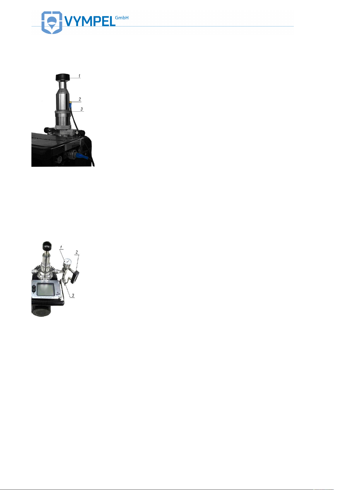
MICROSCOPE
!
=11>?@34@=AB& & C9D&!.H+,/H,NF&
ILLUSTRATION 14 is an exterior view of the microscope
(KRAY3.821.003).
The optical system is positioned immediately above the high-pressure
chamber. Equipped with 40X magnification, this system makes it possible to directly monitor processes taking place on the mirror’s surface
inside the measurement chamber to visually evaluate the compositional quality of the gas (see also 1.3).
The microscope is mounted onto the analyzer by way of a threaded
coupling integrated into the housing for this purpose.
Important components:
• Eyepiece (Pos.1);
• Electrical socket for the lighting system LED (Pos.2);
• Focusing ring (Pos.3)
Gas flow / gas pressure
control system (Model
001)
!
=11>?@34@=AB& & CRD&Y"/&G%,Q&"#K&
*"/&N+F//$+F&H,#E+,%&/)/EFJ&
The gas flow / gas pressure control system Model 001
(VMPL5.183.001) (ILLUSTRATION 15) displays information about
the operating pressure within the analyzer’s measurement chamber.
This system also provides a means to not only adjust the pressure
but also regulate the gas flow rate during the measurement process
(0.5 – 1NL/min).
Included in delivery of the gas flow / gas pressure control system are:
• Manometer (Pos.1);
• Float flow meter with metal housing (Pos.2);
• Flow rate fine adjustment valve (Pos.3);
• Mounting and connecting elements
Refer to Appendix C for a mounting diagram of the gas flow and gas
pressure control system.
Please note:
Most of the systems and system modules are attached to the analyzer by
means of quick-coupling connectors. The advantage such connectors provide is
that no tools or special skills are needed for the installation of various modules
and installation can be accomplished in the shortest mount of time.
!
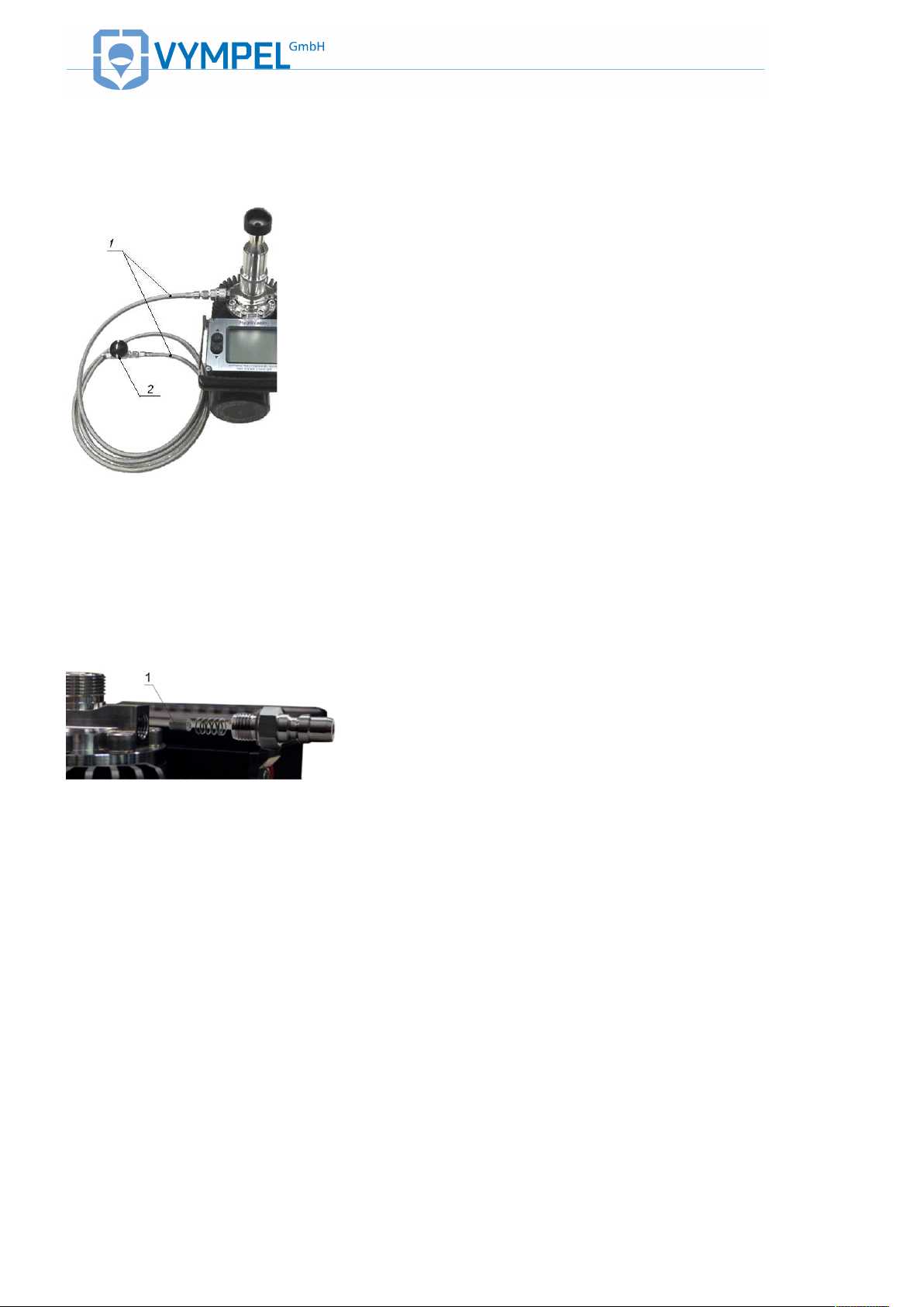
GAS DELIVERY SYSTEM
MODEL 001
!
=11>?@34@=AB& & CTD&Y"/&KF%.-F+)&/)/EF J&
The gas delivery system provides a hermitically sealed
connection between the analyzer and the sample extraction
site. In addition, this system makes it possible to evenly
regulate delivery of the sample gas to the Hygrovision’s
measurement chamber.
Included in delivery of the gas delivery system are:
• Flexible high pressure hose (Pos.1;
ILLUSTRATION 16);
• Fine control valve (Pos.2; ILLUSTRATION 16)
Refer to Appendix D for gas delivery system assembly
instructions..
Please note:
The fittings included in delivery make it possible to connect the analyzer with various measurement equipment, devices, and systems in
the shortest amount of time and do not require additional tools or specialized skills.
PARTICLE FILTER
!
=11>?@34@=AB& & C;D&Z,/.E.,#&,G&ELF&N"+E .H%F &G.%EF+ &
The analyzer is also equipped with an integrated particle filter
in order to remove solid particulates and other mechanical
contaminates from the sample gas. This filter (FE73A-15) is
positioned in the inlet side of the gas delivery housing (Pos.
1; ILLUSTRATION 17) and protects the condensation mirror from possible damage from solid particulates and contaminates in the gas mixture.
The particle filter is included with delivery of the analyzer and
is preinstalled in the analyzer’s housing prior to initial delivery.
A replacement filter cartridge is included with the additional
components delivered with the analyzer as standard equipment.
Please note:
There is a replacement filter cartridge included with the analyzer as
standard equipment. Additional replacement cartridges can be ordered
from Vympel at any time.
GLYCOLS AND HEAVY
HYDROCARBONS FILTER
When taking measurements to determine the dew point of
water, it is common for a variety of gas mixtures to have high
levels of glycol and heavy hydrocarbons. A specially designed filter (KRAY6.451.017) is used for the taking of measurements under these conditions. This filter is included as a
standard additional component with the Hygrovision BL.
(ILLUSTRATION 18).
The filter is installed directly in front of the fine control valve
!
!
=11>?@34@=AB& & C8D&Y%)H,%/&"#K&LF"- )&( I &G.%EF + &
at the end of the flexible high-pressure hose of the gas delivery system (VMPL6.450.001).
In terms of active filtering, the average service life of the filter
cartridge is eight hours. Therefore, the replacement interval
depends in large measure on the type and composition of
heavy hydrocarbons.
Usage requirements as well as detailed information about the
filter can be found in the manual (KRAY6.451.017ET), which
is included with delivery.
The glycol and heavy hydrocarbon filter is delivered with the
analyzer as standard equipment.
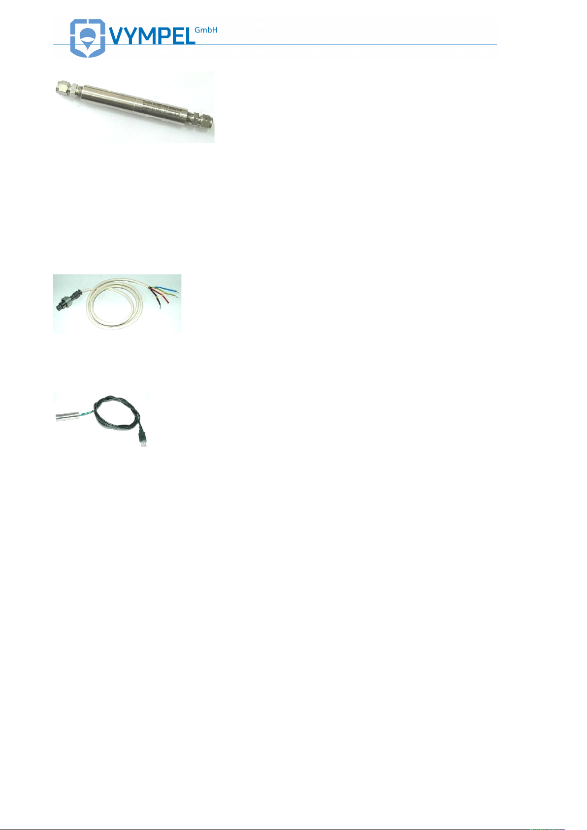
EXTERNAL POWER SUPPLY CABLE
!
=11>?@34@=AB& & CVD&Z,QF+&/$NN%)&H"W%F&
The external power supply cable (Illustration 20) is included
with the analyzer as standard equipment. It serves not only to
provide the device with electricity but also to transmit measurement data by way of the RS 485 interface using the standard Modbus/RTU protocol.
Please refer to Table 5 for instructions concerning electrical
configuration and connection..
IR ADAPTER
!
=11>?@34@=AB& & 6:D&=3&4K"NEF+&
The analyzer’s integrated infrared (IR) port can be connected
to a computer by means of the IR adaptor (KRAY5.999.005).
The position of the IR port is shown in Pos.8;
ILLUSTRATION 11.
Additional components that are available for order as optional
accessories include:
• Supplemental cooling system VMPL5.880.003;
• Tripod (Libec TH-650DV);
• Sample extraction system KRAY4.078.091(- 01);
• Pressure reduction system VMPL2.848.005;
• High-pressure outflow module VMPL4.078.025;
• For a detailed list of the Hygrovision BL’s standard
and optional components, please refer to Table 3,
Point 1.12.
!
SUPPLEMENTAL COOLING SYSTEM
!
=11>?@34@=AB& & 6CD&?$NN%FJF#E"%&H,,%.#*& &
/)/EFJ&
The supplemental cooling system (VMPL5.880.003) should
be used when measuring dew point values below -30°C at
ambient temperatures above +30°C and at pressures over
100 bar (ILLUSTRATION 21).
The cooling system consists of a container filled with carbon
dioxide, two connector fittings, and a regulator valve to control the flow of refrigerant.
The system is connected to the outlet nozzle of the venting
channel (Pos.7; ILLUSTRATION 11).
Please refer to Appendix E for mounting instructions.
For a detailed description of the supplemental cooling system
please refer to “Special considerations when measuring dew
point at very low temperatures ”
TRIPOD
In order to make operating the analyzer more convenient
when in the field, the Hygrovision can be mounted on a Libec
TH-650DV tripod.
A tripod attachment point is integrated into the underside of
the Hygrovision’s housing. When mounted, the analyzer can
be oriented in the desired position.
SAMPLE GAS EXTRACTION SYSTEM
The optional sample extraction system (KRAY4.078.091 or
KRAY4.078.091-01) can be installed to create a stationary
sample gas extraction site. The system set consists of the
sample extraction apparatus (or a bypass valve) and a membrane filter for the removal of liquids and particulates from the
gas sample.
Information regarding mounting and operating this system as
well as ordering replacement filter elements can be found in
the manual delivered with the set (KRАY4.078.091EТ or
KRAY4.078.091-01ET).
!
PRESSURE REDUCTION SYSTEM
=11>?@34@=AB& & 66&
The pressure reduction system (VMPL2.848.005) provides
for the reduction of the sample gas pressure from the working pressure (max. inflow pressure is 250 bar) to a pressure
within the range 0.30 – 35 bar.
The module includes a heating element to pre-warm the gas
sample in order to prevent premature condensation due to
the Joule-Thomson effect (a drop in temperature that is a
consequence of a drop in pressure in the gas mixture).
ILLUSTRATION 22 shows an overall view of the Pressure
Reduction System (PRS). For a schematic drawing, please
refer to Appendix F.
Detailed mounting and operating information can be found in
the manual (VYMP2.848.005RE) delivered with the PRS.
HIGH-PRESSURE
VENTING MODULE
The venting module (VMPL4.078.025) is used to channel the
sample gases flowing out of the Hygrovision’s measurement
chamber into the main venting line, in those situations where
the Hygrovision is used as a reference analyzer (Appendix
G).
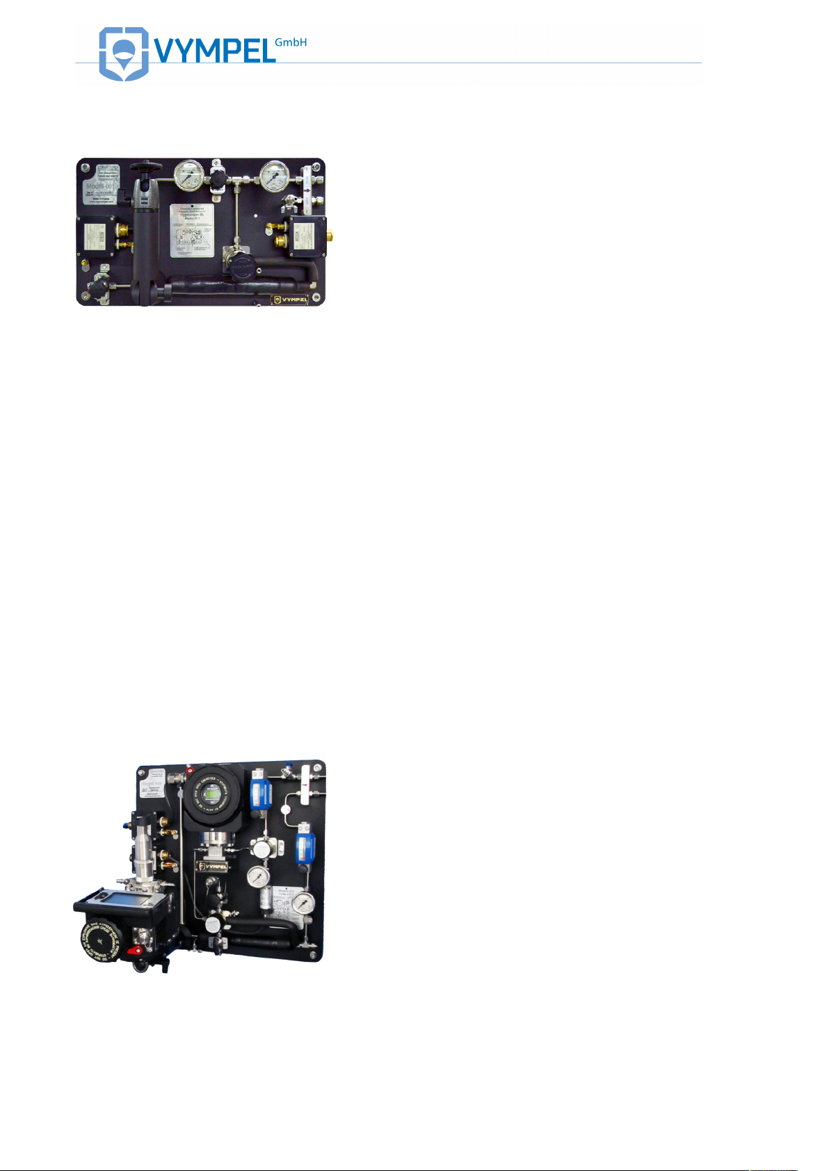
GAS PREPARATION SYSTEM
SGA-003
!
=11>?@34@=AB& & 6MD&?Y4&::M&.#H%7&( )* + , - ./., # &0 1 &
The SGA 003 gas preparation system, or simply SGA,
(ILLUSTRATION 23) provides for the removal of various
aerosol and mechanical contaminants from the sample gas at
a working pressure of up to 160 bar.
The SGA is designed to accommodate the optional use of a
Hygrovision BL as a temporary reference analyzer. To that
end, a foldout mounting arm, and supplemental sample gas
connection points are integrated into the SGA’s construction.
In addition, the SGA is also fitted with a supplemental access
point on the explosion-proof terminal box in order to connect
the Hygrovision BL to an external power supply and link it to
the data transfer system.
!
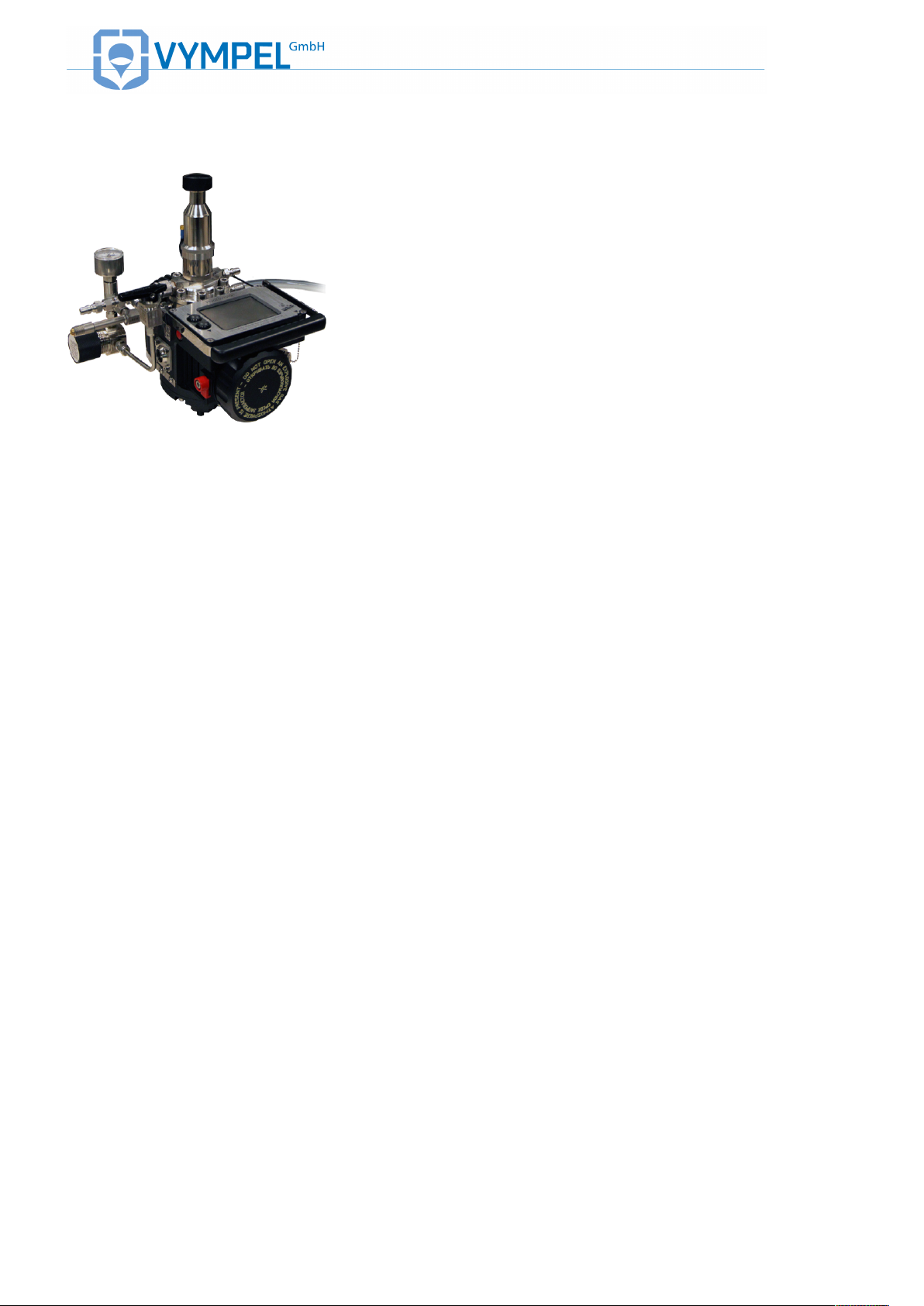
1.7. CONTROL AND DISPLAY ELEMENTS
The analyzer has the following control elements:
On / off button (Pos.9; ILLUSTRATION 11);
Control buttons (Pоs.11; ILLUSTRATION 11) for regulating
the temperature of the condensation mirror.
The touch screen display (Pos.10; ILLUSTRATION 11) is
used to set and adjust the analyzer’s operating parameters.
The display presents information in the form of text and
graphics.
The touch screen stylus can be used to operate the display
(Pos. 14; ILLUSTRATION 10).
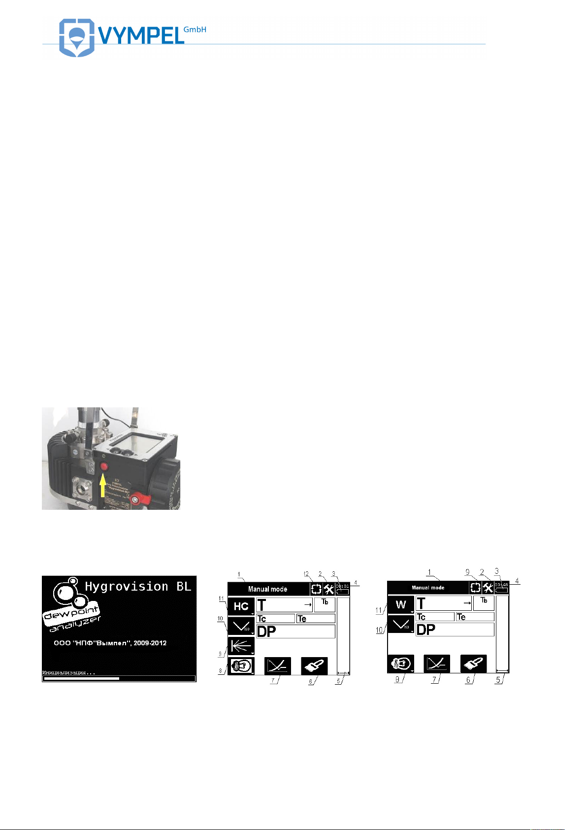
1.8. THE ANALYZER’S MENU
TURNING ON THE ANALYZER
=11>?@34@=AB& & 69&
To turn on the Hygrovision BL press and hold the on/off button for several seconds (Illustration 24).
After the analyzer has been switched on, the touch screen
will display the software version information for two to three
seconds. (Illustration 25)
The BL is ready to begin measurement operations when the
software message is no longer displayed. The analyzer will
automatically revert to the operation at which it was set
when turned off (Illustration 26, 27).
The following control “icons” are displayed on the analyzer’s
screen:
!
=11>?@34@=AB& & 6R&
!
=11>?@34@=AB& & 6T&
!
=11>?@34@=AB& & 6;&
!
!
Operating mode
Shows the currently selected operating mode (Pos.1
ILLUSTRATION 26; ILLUSTRATION 27);
Mode selection
Used to select the desired operating mode (Pos.12,
ILLUSTRATION 26; ILLUSTRATION 27);
Properties
Used to select and access the analyzer’s basic operating parameters in order to make adjustments (Pos.2, ILLUSTRATION
26; ILLUSTRATION 27) A description of the properties menu is
included in Appendix I.
Measurement channel
Used to select the desired measurement type:
• Dew point of water (channel W) or
• Dew point of hydrocarbons (channel HC)
(Pos.11, ILLUSTRATION 26, ILLUSTRATION 27);
Mirror-cooling modality
a
Used to select the mirror-cooling mode when taking measurements manually:
• a) Cooling of the condensation mirror at a continuous
preprogrammed rate (Pos.10, ILLUSTRATION 26;
ILLUSTRATION 27);
b
• b) Stepwise cooling of the condensation mirror by prepro-
grammed temperature intervals (Pos.10, ILLUSTRATION
26; ILLUSTRATION 27).
Laser activation icon
Used to switch the laser on and off (Pos.9, ILLUSTRATION 26;
ILLUSTRATION 27).
This icon only appears when the microscope lighting button has
been activated. The laser is preset in the on position.
Rough DP – Scan
This button activates a scanning process that finds a preliminary
dew point value in order to establish the basic temperature range
within which an accurate dew point value can be measured
(Pos.7, ILLUSTRATION 26, ILLUSTRATION 27).
Microscope lighting
Used to switch the microscope (vertical) lighting on and off
(Pos.8, ILLUSTRATION 26; ILLUSTRATION 27)
Mirror-cleaning mode
Used to activate the mirror-cleaning mode. In this mode the condensation mirror is heated to a specific temperature in order to
free the mirror surface of condensate residue by means of evaporation (Pos. 6, ILLUSTRATION 26; ILLUSTRATION 27).
!
Measurement scale
Used to change the measurement scale during the measurement
process (Pos. 5, ILLUSTRATION 26; ILLUSTRATION 27)
DISPLAYED INFORMATION
• Battery charge status – Pos.3 (ILLUSTRATION 26;
ILLUSTRATION 27);
• Timer – Pos.4 (ILLUSTRATION 26; ILLUSTRATION
27);
• Current temperature of the condensation mirror – Т;
• Housing temperature – Tb;
• Condensation temperature – Tc;
• Evaporation temperature – Te;
• Temperature interval during mirror cooling - ;
• Signal level of the photodiode - U;
• Dew point temperature – DР.
In stepwise cooling mode an automatic timer is activated
which displays the time spent at each temperature level.
The battery status display consists of nine segments — each
segment represents 10 percent of the battery’s charge.
PROPERTIES
!
=11>?@34@=AB& & 68D&Z+,NF+E.F/D&?)/EFJ&'&
ANF+"E.#*&/)/EFJ&
When the icon is tapped, additional information is displayed.
The window that opens when the properties icon is tapped
displays information about the operating system
(ILLUSTRATION 28), the time and date (ILLUSTRATION
29), and the battery status (ILLUSTRATION 30).
!
!
=11>?@34@=AB& & 6VD&Z+,NF+E.F/D&?)/EF J&'&["EF&
"#K&E.JF&
Use the < and > icons to navigate between individual menu
points.
Please note that the date and time are set using the Settings
menu (see also Appendix I).
!
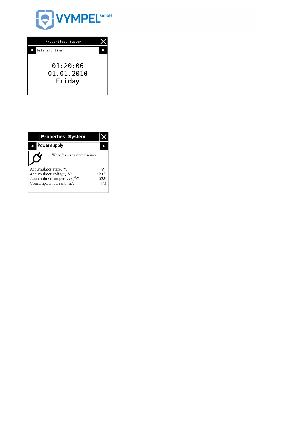
=11>?@34@=AB& & M:D&Z+,NF+E.F/D&?)/EF J&'&Z,QF+&
/$NN%)&
The Hygrovision’s battery should be fully recharged as described in the manual (KRAY5.122.007 ET) when the charge
falls below 20%.
!
ANALYZER CHECK
!
=11>?@34@=AB& & MCD&@+"#/K$HF+&H%F "# .#* &J,KF&
In order to check the functionality of the analyzer follow these
steps:
Tap the icon to switch to the mirror-cleaning mode
(Pos.6, ILLUSTRATION 26; ILLUSTRATION 27)
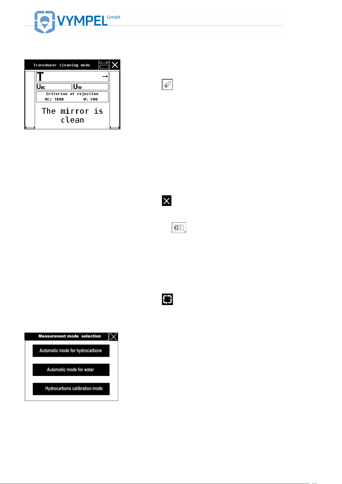
The analyzer’s display will show the “Transducer cleaning
mode” window (ILLUSTRATION 31)
If the device is operating normally, the condensation mirror
should heat to temperature of +50° ± 0.1° C (Т value).
Please note:
Should there continue to be residue on the surface of the mirror after
the mirror-cleaning cycle has been completed, the error message “The
mirror is dirty” will be displayed. In this case it is necessary to repeat
mirror cleaning as described in Point 5.2 .
Tap the icon to switch to the main menu.
Check that the microscope lighting is working properly by
tapping the icon.
When the microscope lighting is switched on, the symbol appears as a black drawing on a light background.
When this lighting is switched off, the symbol, appears as a
light drawing on a dark background.
AUTOMATIC DEW POINT
MEASUREMENT MODE
Tap the icon (Pos12, ILLUSTRATION 26;
ILLUSTRATION 27) to switch to automatic dew point
measurement mode.
!
=11>?@34@=AB& & M6&
Select one of the three modes that displayed in the window
that opens (ILLUSTRATION 32):
• Automatic mode for hydrocarbons
• Automatic mode for water
• Hydrocarbons calibration mode
To activate the desired mode, simply tap the related field.
!
!
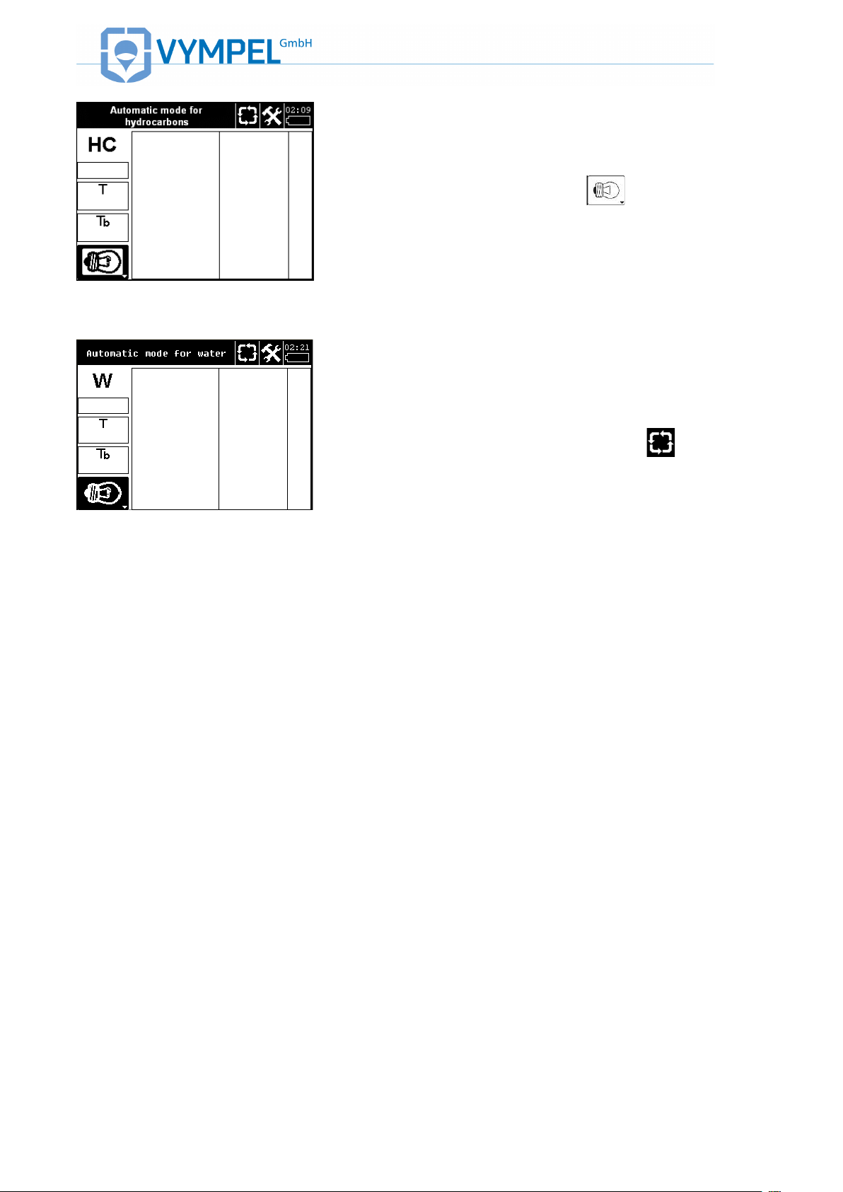
=11>?@34@=AB& & MM&
In order to visually observe the measurement process in
automatic mode for hydrocarbons, the microscope lighting
must be activated by tapping the icon.
(ILLUSTRATION 33).
!
=11>?@34@=AB& & M9&
In the automatic mode for water, the microscope lighting is
switched off (,--./0120,34! ! #$). Visual monitoring of the
measurement process in this mode is carried out with the
microscope lighting turned off.
In order to switch between modes tap the icon again
(Pos.12, ,--./0120,3 4! ! "&5!,--./01 2 0 ,3 4! ! "') and select the
desired operation by tapping the related field 6,--./0120,34! !
#"78
TURNING OFF THE ANALYZER
To turn off the analyzer, press the red button on the left side of
the touch screen housing (Pos. 9, ,--./ 0 1 2 0 ,3 4! ! **7!and hold it
down until the display switches off (about five seconds).

!
1.9. CONNECTING
PERIPHERAL DEVICES
The following connection points are located on the right side of
the analyzer’s housing:
• ХР2 – used for maintenance purposes
• ХР3 – microscope lighting connection socket (Pos.5 ;
,--./0120,34! ! *+)
• XР1 – socket for connecting the analyzer to an external
power supply and for transferring measurement data
over a RS-485 interface using the Modbus/RTU – Protocol (Pos.6; ,--./ 01 2 0 ,34! ! *+)
A description of the Modbus register is included in 299:;<=>!?.
Attention!
The sockets (Pos. 4, 5) are intrinsically safe devices.
Sockets ХР2 and ХР3 have light blue caps.
The IR port is located on the left side of the analyzer’s housing (Pos.8; ILLUSTRATION 11). This connection port
makes it possible to connect the Hygrovision to an terminal
module or computer in order to transfer measurement data
via the IR adapter (KRAY5.999.005), which is included with
delivery as a standard component.
Measurement data is transferred using the standard terminal
programs Hygrovision.exe (299:;<=>!@).
!
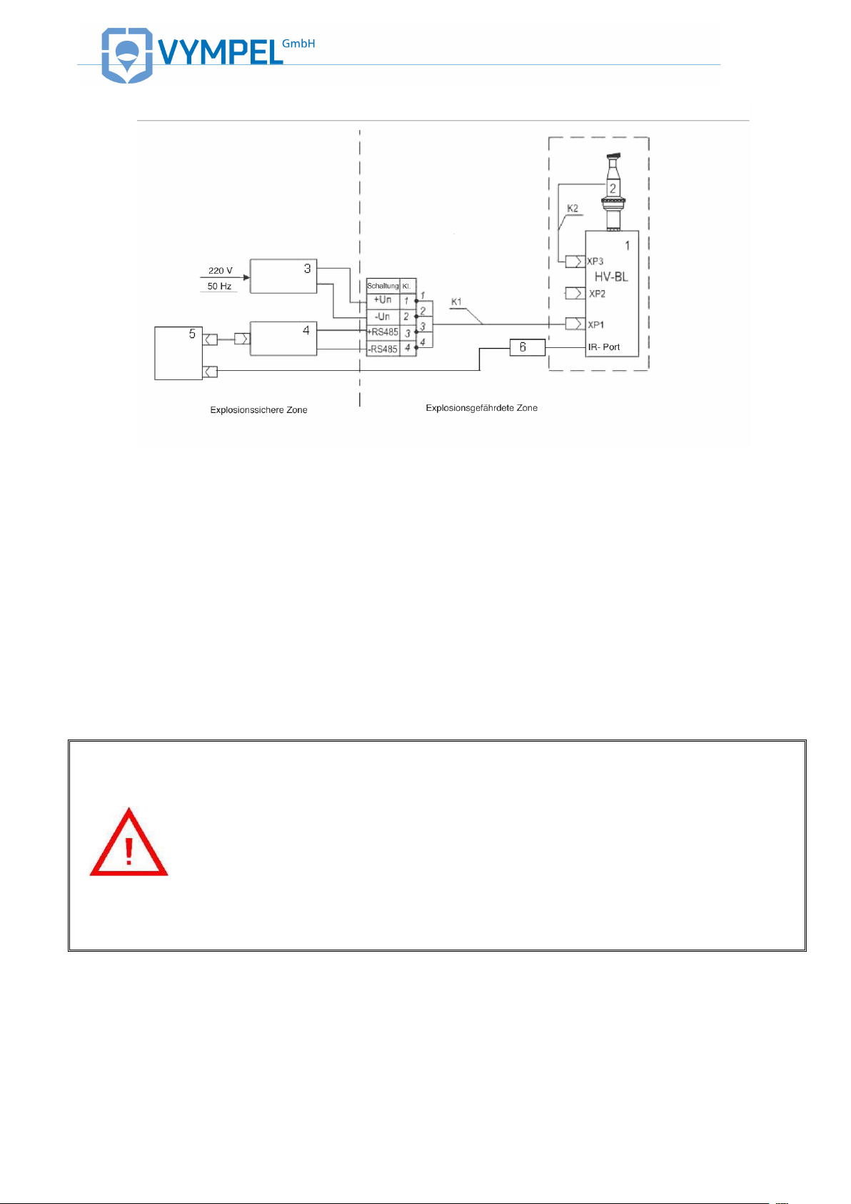
=11>?@34@=AB& & MRD&?HLFJ"E.H&K+" Q .# *&G, +&EL F &H, # #F H E.,#&,G&NF+.NLF+"%&KF-.HF/&
Position of elements in illustration 35:
1 – Hygrovision BL dew point analyzer
2 – Microscope (KRAY3.821.003)
3 – AC power adapter (12- 32) V / 15 W
4 – Interface connector RS – 232 / 485
5 – Computer terminal
6 – IR Adapter (KRAY5.999.005)
К1 – Cable (KRAY4.841.082)
К2 – Cable (VMPL4.841.007)
Attention!
The AC power cable is connected to the analyzer via a supplemental junction box.
Within the junction box, connection of the intrinsically safe and not intrinsically safe
electrical circuits must be carried out separately, in accordance with GOST
R52350.11-2005 and Point 6 of this manual.
&
!
&&&
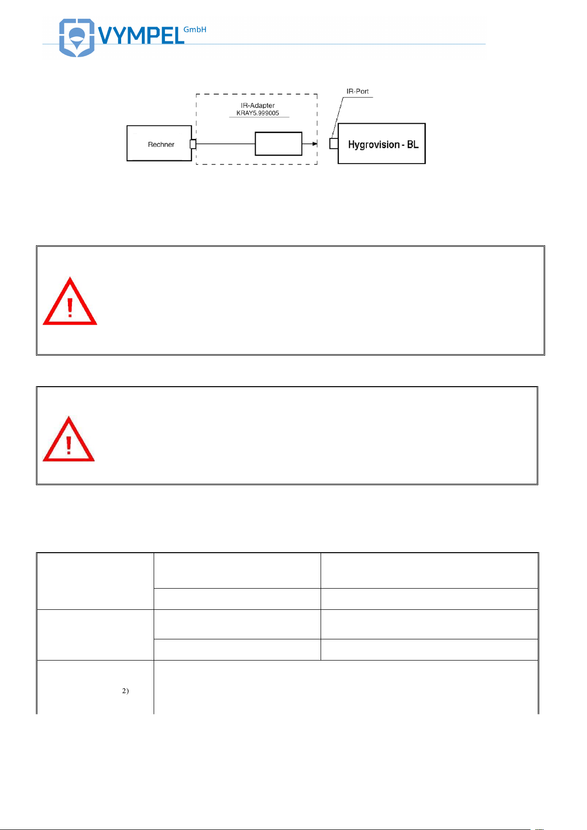
=11>?@34@=AB& & MTD&I,##FHE.,#&,G&"&H ,JN$EF+&EF+J.#"%&-."&ELF&=3&N,+E
Attention!
The terminal computer and the IR adapter (KRAY5.999.005) are not explosion-proof
devices.
For this reason, connection of these devices to the analyzer may only be carried out
in explosion-proof zone.
1.10. SPECIFICATIONS
@"W%F&C&
Water
-30 ºС – TH
Measurement range
Hydrocarbons
-30 ºС – TH
Water
±0.5 °С
Measurement error
Hydrocarbons
±0.5 °С
Recommended
gas-flow volume
0.5 – 1 Nl/min
Attention!
To ensure the analyzer’s explosion safety, unused socket connections must be secured with the caps included with delivery.
!
Battery-powered operation
= (8.4 – 12.6) V, 4 mА / 15 W
Electrical supply
(Voltage / Power)
External power supply
= (12 – 32) V / 15 W
Battery-powered operation
4 h
Operating time
External power supply
Unlimited
Ambient
Temperature
-10 – +50 0С
Working pressure
≤ 250 bar (dependent on BL version)
Level of housing
protection
IP66
Dimensions
(without micro-
165х204х257 mm
Weight
(without accesso-
7.5 kg
Installation
Suitable for enclosed indoor spaces and open outdoor areas
(hazardous zones)
Sample extraction
connection
Pipe connection module (Dk-Lok connection pipe with an outer diameter of
ø 6mm)
Service life:
Analyzer
Measurement cell
Rechargeable
battery
10 years
3 years
300 charge/ discharge cycles (max. two years)
!
1.11. HYGROVISION BL STANDARD EQUIPMENT
&
&
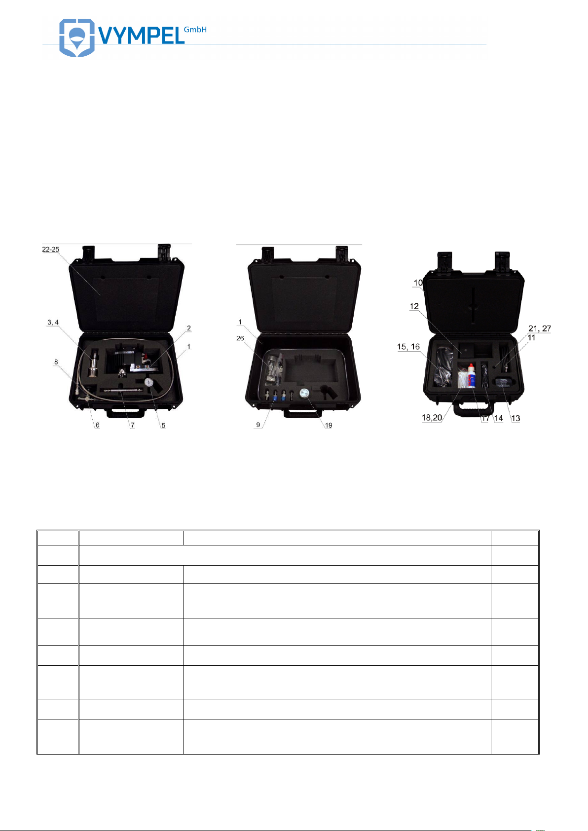
Table 2 gives an overview of the important standard components delivered with the Hygrovision BL.
@LF&N,/.E.,#/&.#&=11>?@34@=AB& & M;\&=11>?@34@=AB& & M8\&=11>?@ 3 4 @ =AB& & MV&H,++F/N,#K&E,&ELF&#$JW F +.# * &.# &E" W %F &6 7& &
&
Table 2.
!
=11>?@34@=AB& & M;&
!
=11>?@34@=AB& & M8&
!
=11>?@34@=AB& & MV&
&
&
@"W%F&6&
Pos.
Article Number
Description
No.
Main components:
1
VMPL 4.161.003
Transport case
1
2
KRAY 2.844.007
Hygrovision BL dew point analyzer set (including the
following accessories)
1
3
KRAY 3.821.003
Microscope
1
4
VMPL.841.007
Cable
5
VMPL 5. 183.001
Gas flow and gas pressure control system Model 001
1
6
VMPL 6.450.001
Gas delivery system Model 001
1
7
KRAY 6.451.017
Filter for the control of glycols and heavy hydrocarbons
1

!
8 – PVC pipe: inner diameter ø 6х1.5, length= 2500 mm
1
9 – Mounting fittings (set)
1
10
VMPL 4.161.004
Transport case
1
11
KRAY 4.841.082
External power supply cable
1
12
KRAY 5.122.007
Battery charger
1
13
KRAY 5.549.006
AC adapter unit BP-06
1
14
KRAY 5.999.005
IR data connection line
1
15 – Power supply adapter cord IBM 16B; 4.5A ; plug 5.5/2.5
1
16 – Power cord with auto cigarette lighter plug 5.5/2.5
1
17 – Eclipse optics cleaner (59 ml)
1
18 – Cotton swabs (package of 50)
1
19
KRAY 4.160.001
Tube of replacement cartridges for filter KRAY6.451.017
(10 cartridges with adsorbent МАU)
1
20
VMPL 8.392.001
Special disassembly key
1
21
VMPL 8.248.005
Sealing ring
Operating documentation and software
22
KRAY
2.844.007RE
Operating manual
1
23
KRAY2.844.007
FD
Form
1
24
KRAY
2.844.007МL
Verification methodology
1
25
KRAY 2.844.00701 D21
Software
1
Additional equipment*
26
VMPL 5.880.003
Supplemental cooling system
27 – Element made of sintered steel (FE73A-15)
– Libec TH-650DV tripod
KRAY 4.160.001
Tube containing additional replacement filter cartridges
KRAY 5.549.006
Power unit BP-06
KRAY 4.078.091
(- 01)
Sample extraction module
130-502
Membrane filter replacement membranes (5 pcs.)
KRAY6.457.022(-01)
VMPL 2.848.005
Reduction unit model 001
VMPL4.078.025
High pressure venting module
* quantity dependent on customer order
Please note:
Depending on technical developments, the shipment inventory and the design of individual elementss may be
different than what is depicted here, however these alterations will have no effect on basic function and intrinsic
safety.

!
!
1.12. EXPLOSION SAFETY PROVISIONS
The analyzer is fitted with a flameproof enclosure and intrinsically safe electrical circuitry to provide safety against explosion (Table 1).
Other design features that ensure the Hygrovision BL is protected against explosion are:
Spark arresting insulation barriers that ensure the intrinsic safety of the electrical connections at
the control buttons.
Bypass diodes and resistors that ensure the intrinsic safety of the electrical circuit connected to
the display unit. These elements reduce the electrical current and voltage to the values allowed
by GOST R 52350.11 for electrical devices in Group II B. This reduction applies for both normal
and emergency operation modes. Electrical sparking is prevented through a combination of resistors and a fuse module.
The sum of the electrical capacity and the inductivity of the electrical circuit that connects the Hygrovision BL to external components via their individual intrinsically safe plugs conform to the
values required by GOST R 52350.11.
Optoelectronic coupling provides galvanic separation of the signal and the internal circuitry of the
Hygrovision BL.
Electrical clearances and seepage, and the stability of the electrical insulation of the intrinsically
safe circuitry are in accordance with the requirements of GOST R 52350.11
The electrical load does not exceed two thirds of the nominal capacity of components that ensure
intrinsic safety.
The construction and electrical properties of the LED conform to the specifications stated in
GOST R 52350.0 and GOST R 52350.1.
The maximal temperatures generated through internal heating, to which the electrical components
and the housing of the Hygrovision BL are exposed do not exceed those allowed in GOST R
52350.0 for temperature class T5.
The HV BL’s electronics unit connection points through the flameproof enclosure meet the requirements of GOST R 523 50.1 for electrical apparatus of subgroup II B.
Lock nuts and adhesives are used to protect against the loosening of the screws, bolts, and nuts
that secure the various elements of the flameproof enclosure as well as the conductor and
grounding terminals. Similarly, locking devices are used to secure self-threading connectors. The
heads of external fixing screws are recessed and can only be accessed using a special tool.
Cable entry points ensure that conductors have a stable and durable connection. Fasteners comply with the requirements of the GOST R 52350.1 – 2005 directive.
The mechanical strength of the flameproof enclosure meets the requirements of GOST R
52350.0-2005 for electrical apparatus of Group II that are exposed to a strong risk for mechanically inflicted damage. The surface areas of the LCD display and the IR interface are limited to

!
prevent the buildup of static electricity.
Integration of electrical ports into the flameproof enclosure complies with the requirements of
GOST R 52350.0 und GOST R 52350.1.
The construction of the HV BL conforms to the general requirements of GOST R 52350.0-2005
for electrical equipment designed to be operated in explosion-hazard areas. The seals and connectors used for structural elements provide an IP 66 level of protection in accordance with GOST
14254.
All applicable explosion protection information is displayed on the housing of the Hygrovision BL
as required by regulation.

!
2. SAFE OPERATION OF THE HYGROVISION BL
2.1. GENERAL SAFETY MEASURES
The Hygrovision analyzer is a class 0I electrical device (as defined by GOST Standards 12.2.007.0
SSBT), in terms of protection against electrical shock.
Do NOT use the HV BL to take measurements in situations where the analyzer will be exposed to corrosive media or an aggressive.
The charging unit must be plugged into a grounded socket (GOST Norm 12.1.030 SSB). Resistance
in the grounding circuit must not exceed 4 ohms.
Installation and removal of the analyzer should be done only after the valve on the sampling device
has been closed and the pressure within the sampling equipment has been adjusted to atmospheric
pressure using the fine adjustment valve.
2.2. EXPLOSION-SAFE INSTALLATION AND OPERATION
Installation and maintenance of the analyzer may only be carried out by qualified personnel. The device should only be operated by individuals who are familiar with the unit’s documentation and the
guidelines for working in explosion-hazard areas. It is strongly recommended that users of the Hygrovision BL receive training and/or instruction provided by Vympel GmbH in order to fully comply with
the above stated requirements.
The analyzer can be operated in both indoor and outdoor explosion-hazard areas in accordance with
GOST R 52350.14-2006 and other normative standards that regulate the operation of electrical devices in explosion-hazard areas (see 1.2).
A visual inspection of the analyzer must be carried out before the unit is installed to ensure that the
device is in accordance with the information presented in Appendix B. Specific points to check include
but are not limited to the ignition-proof markings, the mechanical integrity of the housing, the state of
the Hygrovision’s various components, and the proper connection of the external intrinsically safe
equipment (the microscope).
Make all necessary electrical connection in accordance with the schematic drawing in section 1.9. After the unit has been installed, check that it is properly grounded and that the grounding resistance
does not exceed 4 ohms.
During installation, it is essential to avoid any friction or shocks that could lead to the creation of
sparks.
Please observe the following guidelines during installation:
• Properly plug in all detachable connection;
• Make sure that all of the housing screw-connector coverings are fully in place, as are all of the
lids and locking mechanisms.

!
When in operation, the analyzer should undergo a regular visual inspection that includes the following
points:
• Check the integrity of all the seals;
• Check that all of the lids and caps are properly in place;
• Check the integrity of the insulation of all the wiring (power supply and data transfer);
• Check the integrity and connection of the grounding wire;
• Check for the presence of dents or other visible mechanical damage, dust, or contamination
that could interfere with the analyzer’s operation.
• Use of an analyzer that is damaged or defective is strictly prohibited.

!
3. PREPARING THE ANALYZER
FOR OPERATION
3.1. GENERAL REQUIREMENTS
UNPACKING AND VISUAL
INSPECTION
Upon receipt, please confirm that the packing in which the analyzer
is delivered is in good condition. Should the packing show signs of
damage, please document this, and contact customer services at
Vympel GmbH.
Carefully unpack the analyzer and its accessories. Refer to the
packing list to ensure that the delivery is complete.
Confirm that there has been no damage during transportation.
OPERATING RESTRICTIONS
Please refer to the restrictions that pertain to analyzer operation
which are listed under point 2.2 of this manual.
Attention!
Completely charge the rechargeable battery of a new Hygrovision before putting the
analyzer into operation for the first time.
PREPARING THE
RECHARGEABLE
BATTERY FOR ANALYZER
OPERATION
A battery charger (KRAY5.122.007), specially designed for charging
the Hygrovision’s battery pack is included with delivery.
The battery can be charged by connecting it to either:
• a 220 V A/C power supply
or
• a 12 V D/C power source
Instructions for using the battery charger can be found on the
charger’s label (KPAY5.122.007 EТ).

!
Attention!
The Hygrovision’s battery must be charged/recharged only in an explosion-proof zone.
SAMPLE EXTRACTION
When selecting a sample extraction site, the following points should be
considered:
! The ambient temperature and the relative humidity lie within the pa-
rameters listed in table 1, point 1.1;
! The temperature of the sample gas as it enters the measurement
chamber must not be lower than temperature of the gas at the extraction site.
If the temperature of the sample supply line (the ambient temperature) is
below the temperature of the sample gas at the point of extraction, the
sample supply line must be heated by means of an electric heating element.
3.2. CONNECTING THE ANALYZER
Place the analyzer on a level surface or mount it on the tripod near
the extraction site. Take care that the bearing surface provides sufficient support for the analyzer.
Attach the gas delivery system (VYMP6.450.001; Pos.1,
ILLUSTRATION 40) to the inlet port of the analyzer’s measuring
chamber. Confirm that the high-pressure valve is closed.
Next, attach the gas flow and gas pressure control system
(VYMP5.183.001; Pos. 3, ILLUSTRATION 40) to the outlet port of
the measuring chamber (Pos. 2). Confirm that the fine adjustment
valve of the gas flow / gas pressure control system is closed.

!
!
=11>?@34@=AB& & 9:&
Both of these systems use quick-connect couplers to attach to the
analyzer’s inlet and outlet ports in order to not only reduce the time
required for (de)installation but also to ensure an airtight seal at
each of these points.
The analyzer connects to the gas supply by means of a flexible
high-pressure hose equipped with a fine adjustment valve (Pos.2).
Connect the end of the hose to outlet port of the extraction system’s shut-off valve. (Dk-Lok connector with an outer diameter of ø
6mm).
Gas that has passed through the measuring chamber is vented
through a PVC hose (included with delivery) that is connected to
the outlet nozzle (Pos.5) of the gas flow / gas pressure control system.
The gas flow can be altered as desired by means of the fine adjustment control valve on the gas flow / gas pressure control system. The manufacturer recommends an optimal volume flow of 0.5
– 1.0 Nl/min.
If the gas composition includes a large number of early-condensing
hydrocarbons that interfere with the clear visual detection of the
formation of water condensation, the user should install the supplemental filter for the control of heavy hydrocarbons
(KRAY6.451.017; included with delivery).
This filter should be mounted between the high-pressure hose and
the gas delivery system (VYMP6.450.001).
Attention!
When (de)installing pressurized devices in the sample gas extraction system or the
gas preparation system (SGA), it is necessary to reduce the operating pressure to
atmospheric pressure.
TESTING SEAL INTEGRITY
After the analyzer has been installed it is necessary to check that
integrity of the sample delivery system connections using the following procedure:
1. Close the valve on the gas flow / pressure control system;
2. Slowly open the sample extraction system shutoff valve
and the valve at the inlet port of the analyzer’s measuring
chamber;
3. Apply a soapy emulsion to the points of connection be-
tween the gas delivery system, the measuring chamber,
and the gas flow and pressure control system, including
between the locknut and connecting sleeve at each joint.

!
4. If bubbles are seen forming in the soapy emulsion it is a
sign that the corresponding connection is not properly
sealed. The connection seal must be reseated to ensure
air tightness.
Attention!
In situations where the dew point of inflammable gases is being measured, it is
necessary to ventilate the analyzer’s measuring chamber and the sample gas delivery lines for 10 to 20 minutes before connecting the device to the power supply.
3.3. FUNCTIONAL TEST
When carrying out a functional test, use the following procedures (as
described in detail below):
1. Switch on the analyzer;
2. Check the microscope lighting;
3. Check the condition of the condensation mirror;
4. Confirm that the thermoelectric battery is working properly;
5. Check that the date and time are correct;
6. Check the charge status of the rechargeable battery pack
7. Switch the analyzer off
SWITCHING ON THE
ANALYZER
!
=11>?@34@=AB& & 9C&
Press the red button on the left side of the analyzer to switch the device on (ILLUSTRATION 41).
The operating program (OP) requires one or two seconds to load.
When the program has completed the startup sequence, the touch
screen will display the last operating mode to which the device was
set (ILLUSTRATION 26; ILLUSTRATION 27; ILLUSTRATION
33; ILLUSTRATION 34).
When the analyzer is switched on, the temperature of the condensation mirror (T) should largely correspond to the temperature of the
housing (Tb), with a maximum deviation of ≈ ± 0.5°C.
CHECKING THE MICROSCOPE
Confirm that the microscope lighting is operating properly by tapping
the “microscope lighting” icon (Pos.8, ILLUSTRATION 26;

!
LIGHTING
ILLUSTRATION 27). Look through the microscope to visually confirm that the lighting switches on and off.
Make sure that the microscope is optimally adjusted for viewing the
surface of the condensation mirror.
Use the focusing ring to adjustment the sharpness of the image.
CHECKING THE
CONDENSATION MIRROR AND
THE THERMOELECTRIC
BATTERY
Activate the “Transducer Cleaning Mode” as described in Point 4.2.
It should only take a few minutes for the condensation mirror to heat
up to a “cleaning” temperature of about +50 °C ± 0.1 °C.
If there are no problems during this process, it can be assumed that
the thermoelectric element is functioning properly.
Check that the signal levels for UHC und UW are within tolerance.
If the system message “The mirror is dirty” is displayed, carry out
technical maintenance as described in Point 5.2.
DATE AND TIME
Open the “Properties: System” menu window for “Date and Time” as
described in Point 1.8 (ILLUSTRATION 29).
Should these parameters require correcting, go the “Properties”
menu and follow the procedure as described in Appendix I.
BATTERY PACK CHARGE
STATUS
Open the “Properties: System” menu window for “Power supply” as
described in Point 1.8 (ILLUSTRATION 30).
If the rechargeable battery pack (BP) is in good condition, the parameters that are displayed will be within the ranges depicted here.
@"W%F&M&
Parameter
Unit
Acceptable
value
Charge status
Qa
10 – 100%
Voltage
Ua
9.0 – 12.6 V
Operating current
Ia
0.01 – 2.5 A
Temperature
Ta
-20 °C – + 60 °C
If the charge status of the BP is below 20%, fully recharge it according
to the instructions provided on the recharging unit label
(KRAY5.122.007ET).
SWITCHING OFF THE
ANALYZER
Switch the analyzer off by pressing and holding the red button until
the touch screen goes off. (ILLUSTRATION 41).

!
4. OPERATING THE HYGROVISION BL
4.1. PRECAUTIONARY MEASURES
The analyzer may be operated in both indoor and outdoor explosion
hazard areas in accordance with GOST R 52350.14-2006 and other
normative documents that regulate the use of electrical devices in explosion hazard areas.
Only fully qualified personnel are to install and operate this device.
Further, this device may only be used by persons who are completely
familiar with the guidelines and normative documents pertaining to
working in explosion hazard areas. It is therefore strongly recommended that the relevant personnel receive instruction and training
from Vympel GmbH.
During installation of the analyzer it is essential to avoid any friction or
shocks that could generate sparks.
Before the analyzer may be (de)installed the shut-off valve on the
sample extraction system and the shutoff valve on the gas delivery
system must both be in the closed position and the pressure within the
analyzer’s measurement chamber must be reduced to the ambient
atmospheric pressure.
4.2. HANDLING THE HYGROVISION BL
PREPARING TO TAKE
MEASUREMENTS
Before taking any measurements, please make sure that the analyzer and its accessory parts are all in proper working order.
When preparing the Hygrovision BL for operation:
• Affix the analyzer to a tripod or place it on a level surface;
• Carefully mount the microscope and plug ends of the micro-
scope lighting cord into the appropriate sockets;
• Connect additional accessories (computer terminal, pressure
transmitter, etc.) to the analyzer at the appropriate points;
• Before switching on the analyzer make sure that all of the
components are mounted in accordance with the requirements of Point 2.2;
• Carry out a functional test of the analyzer immediately before
beginning to take measurements. Also check the power
source as described in point 1.8 of this manual.

!
HEATING THE
CONDENSATION MIRROR
!
=11>?@34@=AB& & 96&
Always clean the mirror before taking measurements by activating
the “Transducer cleaning mode”.
Tap the icon to activate this mode (Pos.6; ILLUSTRATION
26; ILLUSTRATION 27).
When the icon is tapped the “Transducer cleaning mode” menu
window is opened. The information displayed in this mode includes
values for the mirror temperature (T), the signal levels for hydrocarbons (UHC) and water (UW), and signal level rejection criteria, as well
as a text message confirming that the mirror is either clean or “dirty”.
The process of heating the mirror to 50 °C is depicted as a changing
value for T (,--./0120,34! ! $").
CLEANING THE MIRROR
If the message “The mirror is dirty” is displayed after the “Transducer
cleaning mode” cycle is complete (,--./0120,34! ! $#), it will be necessary to clean the condensation mirror according to the instructions
found under Point 5.2.
!
=11>?@34@=AB& & 9M&
When the desired measurement pressure has been reached, ensure
that the microscope and the microscope lighting are adjusted to provide optimal viewing of the surface of the condensation mirror.
Adjust the sharpness of the mirror’s image using the focus ring on the
microscope (Pos.3 ,--./0120,34! ! *$)
ADJUSTING THE LIGHTING
INTENSITY
When working out-of-doors it may be desirable to adjust the intensity
of the condensation mirror illumination in response to various environmental factors and personal preference.
When taking dew point measurements, the process of condensation
can be directly observed visually by means of the microscope
(,--./0120,34! ! *; ,--./0120,3 4! ! ") alternatively, condensation can
be monitored on the display by means of the optical-electric registration system (measurement scale – Pos.5, ,--./0120,3 4 ! ! "&5!
,--./0120,34! ! "'7

!
MIRROR SCAN /
SCANNING MODE
!
=11>?@34@=AB& & 99&
Scanning serves to simplify the process of registering the dew point
manually. In scanning mode, the analyzer establishes an approximate dew point range within which lies the actually dew point.
Tap the function icon (Pos.7; ILLUSTRATION 26;
ILLUSTRATION 27) to begin the scanning process. In this mode
the condensation mirror is cooled at a rate of 0.5 °C per second until
reaching a temperature at which a condensation film of water or hydrocarbons begins to form. When this point is reached the mirror is
automatically reheated to a temperature exactly 10 °C above that at
which the formation of condensation was initially registered.
The signal strengths corresponding to water and/or hydrocarbons
condensation are displayed in the UW and U
HC
menu windows.
In the “Level of fixation” window a value limit for the signal strength
of the UHC and UW channels is displayed. When one of these values
is exceeded the temperature of the mirror will stabilize at the corresponding level. The analyzer will determine whether the condensate
is made of water or hydrocarbons based on which value is exceeded.
When the scanning process is completed, the letters HC will be displayed if the analyzer registers hydrocarbon condensation whereas
the letter W will be shown for water condensation.
To end the scanning process, tap the icon (ILLUSTRATION
44). The analyzer will then be set to standby mode and the mirror
will be maintained at the approximation temperature established in
scanning mode (condensation temperature +10 °C).
At this point, select the desired dew point measurement mode by
tapping the corresponding icon (Pos.10, ILLUSTRATION 26;
ILLUSTRATION 27) to begin the DP measurement process.

!
TAKING DEW POINT
MEASUREMENTS
The Hygrovision BL is designed to provide two methods of dew point
registration:
• Manually controlled dew point registration
• Automatic dew point registration
There are four options for manually controlled dew point registration:
• Hydrocarbon dew point measurement while cooling and
heating the condensation mirror at a preprogrammed rate
• Hydrocarbon dew point measurement while cooling the con-
densation mirror step by step
• Water dew point measurement while cooling and heating the
condensation mirror at a preprogrammed rate
• Water dew point measurement while cooling the condensa-
tion mirror step by step
There are two options for automatic dew point registration:
• Automatic measurement of the hydrocarbon dew point
• Automatic measurement of the water dew point
Dew point results registered in automatic mode are saved in the
analyzers non-volatile memory and can be displayed at any time.
The Hygrovision BL is equipped with an IR-Port and an RS 485 interface for data transfer purposes. The corresponding computer
software (Appendix K) is also included in delivery.
Attention!
When taking measurements for the dew point of water, if a significant amount of
early-condensing hydrocarbons are observed (the formation of non-water drop like
condensation), it will be absolutely necessary to install the filter (KRAY6.451.017)
used for the control of heavy hydrocarbons.

!
!
=11>?@34@=AB& & 9R&
!
=11>?@34@=AB& & 9T&
4.3. HC DEW POINT MEASUREMENT USING
THE PREPROGRAMMED RATE OF COOLING /
HEATING THE CONDENSATION MIRROR
!
1. Select the hydrocarbon measurement channel by activating the
icon (Pos.11, ILLUSTRATION 45). Set the analyzer to the
preprogrammed rate of cooling / heating (per ISO) mode by choos-
ing the icon (Pos.10). Tap the icon to activate the microscope lighting (Pos.8).
2. Push the “down” button (Pos.14, ILLUSTRATION 46) to begin
cooling the condensation mirror at the preprogrammed rate (the factory default setting is 1 °C per minute).
3. As soon as a visually observable film of condensation begins to
form, fix the temperature of the condensation mirror by once again
pushing the “down” button (Pos.14, ILLUSTRATION 46). This fixed
temperature value is shown in the Tc field of the display and the mirror temperature is maintained at this level.
4. Now push the “up” button (Pos.13, ILLUSTRATION 46) to begin
heating the mirror at the preprogrammed rate. As soon as the condensate is observed to begin evaporating push the “up” button again
to fix this temperature. This second fixed temperature value is
shown in the Te field of the display.
In the case of hydrocarbons, the Tc value is, in fact, equivalent to the
Te value. In other words, condensation temperature and evaporation
temperature are the same for hydrocarbons. The fixed Tc and Te
values may not diverge by more than 0.2 °C.
5. The measured dew point temperature is now shown in the DP
field of the display and is stored in the analyzer’s memory.
6. To complete the measurement cycle, tap the icon (Pos.6,
ILLUSTRATION 45) to switch the analyzer to mirror cleaning
mode. At this point the condensation mirror will automatically be
heated to 50 °C and the signal level will be reset to the starting
value.
Pleas note:
Should concurrent condensation of water vapor impair the observation of hydrocarbon condensation, the laser diode can be switched off by tapping the
icon.

!
4.4. HC DEW POINT MEASUREMENT
COOLING THE MIRROR STEP BY STEP
!
=11>?@34@=AB& & 9;&
1. Select the hydrocarbon measurement channel by activat-
ing the icon (Pos.11, ILLUSTRATION 47). Set the
analyzer to step by step cooling mode by choosing the
icon (Pos.10). Tap the icon to activate the microscope
lighting (Pos.8).
2. Begin cooling the mirror by pushing the “down” button
(Pos.14, ILLUSTRATION 46). When the “down” button is
pushed the temperature of the condensation mirror is lowered by 1 °C (factory default setting). The current mirror temperature is shown in the T field of the display. A timer also
appears on the display, which shows how long the mirror has
been at its current temperature.
A newly entered temperature, in other words the next step to
which the mirror will be further cooled, is shown in the
field of the display.
3. Each time the “down” button (Pos. 14, ILLUSTRATION
46) is pushed the newly entered temperature will be lowered
by 1 °C and the timer will be reset to start over.
4. As soon as a visually observable condensation film begins
to form, fix the HC condensation temperature by pushing the
“up” button (Pos.13, ILLUSTRATION 46). The condensation mirror will also be raised by 1 °C and the timer will be
reset.
5. Fixation of the evaporation temperature is analogous to
the process described under point 4.3.
6. To complete the measurement cycle, tap the icon
(Pos.6, ILLUSTRATION 47) to switch the analyzer to mirror
cleaning mode.
Please note:
Should concurrent condensation of water vapor impair the observation
of hydrocarbon condensation, the laser diode can be switched off by
tapping the icon.

!
4.5. WATER DEW POINT MEASUREMENT
USING THE PREPROGRAMMED RATE OF
COOLING / HEATING THE CONDENSATION
MIRROR
!
=11>?@34@=AB& & 98&
1. Select the water measurement channel by activating the
icon (Pos.11, ILLUSTRATION 48). Set the analyzer
to the preprogrammed rate of cooling / heating (per ISO)
mode by choosing the icon (Pos.10). Tap the
icon to deactivate the microscope lighting (Pos.8).
2. Push the “down” button (Pos.14, ILLUSTRATION 46) to
begin cooling the condensation mirror at the preprogrammed
rate (the factory default setting is 1 °C per minute).
3. As soon as a visually observable film of condensation begins to form, fix the temperature of the condensation mirror
by once again pushing the “down” button (Pos.14,
ILLUSTRATION 46). This fixed temperature value is shown
in the Tc field of the display and the mirror temperature is
maintained at this level.
4. Now push the “up” button (Pos.13, ILLUSTRATION 46)
to begin heating the mirror at the preprogrammed rate. As
soon as the condensate is observed to begin evaporating
push the “up” button again to fix this temperature. This second fixed temperature value is shown in the Te field of the
display.
The measured dew point temperature for water is now shown
in the DP field of the display and is stored in the analyzer’s
memory. The condensation mirror is maintained at the
evaporation temperature. Stored dew point values can be
accessed and displayed on the screen at any time.
5. To complete the measurement cycle, tap the icon
(Pos.6, ILLUSTRATION 48). to switch the analyzer to mirror cleaning mode.

!
4.6. WATER DEW POINT MEASUREMENT
COOLING THE MIRROR STEP BY STEP
&
=11>?@34@=AB& & 9V& &
C7&?F%FHE&ELF&Q"EF+&JF"/$+FJF#E&HL"##F%&W)&"HE.-"E.#*&ELF& &.H,#&OZ,/7CC\& &
ILLUSTRATION 49). Set the analyzer to step by step cool-
ing mode by choosing the icon (Pos.10). Tap the
icon to deactivate the microscope lighting (Pos.8).
2. Begin cooling the mirror by pushing the “down” button
(Pos.14, ILLUSTRATION 46).
When the “down” button is pushed the temperature of the
condensation mirror will be lowered by 1 °C (factory default
setting). The current mirror temperature is shown in the T
field of the display. A timer also appears on the display,
which shows how long the mirror has been at its current temperature. A newly entered temperature, in other words the
next step to which the mirror will be further cooled, is shown
in the field of the display.
3. Each time the “down” button (Pos. 14, ILLUSTRATION
46) is pushed the newly entered temperature will be lowered
by 1 °C and the timer will be reset to start over.
4. As soon as a visually observable condensation film begins
to form, fix the W condensation temperature by pushing the
“up” button (Pos.13, ILLUSTRATION 46). The condensation mirror will also be raised by 1 °C and the timer will be
reset.
5. Fixation of the evaporation and dew point temperatures is
analogous to the process described under point 4.5.
T7&@,&H,JN%FEF&ELF&JF"/$+FJF#E&H)H%F\&E"N&ELF& & .H,#&OZ,/7T\J& &
ILLUSTRATION 49) to switch the analyzer to mirror cleaning mode..
Please note:
The manufacturer recommends that during step by step heating and
cooling, the mirror remain at each temperature for about 1 minute.

!
4.7. HC DEW POINT MEASUREMENT IN
AUTOMATIC MODE
!
=11>?@34@=AB& & R:&
Tap the icon to set the analyzer to automatic mode for
haydrocarbons. Refer to point 1.8.
When measuring the hydrocarbon dew point in automatic
mode the following information will be shown on the left side
of the display (see ILLUSTRATION 50):
• Current measurement mode HC;
• HC signal level;
• Current temperature of the condensation mirror T;
• Current temperature of the housing Tb;
• Icon for activating the microscope lighting
Measurement of the HC dew point is done by slowly cooling
the condensation mirror at a preprogrammed rate (the factory
default setting is 1 °C/min.) until the temperature is reached
at which hydrocarbons begin to form a condensation film.
The measurement results are listed in a table that shows the
following information:
• Time of the measurement;
• Dew point value in °C;
• Pressure in bar (when a pressure analyzer is con-
nected)
To erase the analyzer’s memory (measurement values
shown in the table) push the “up” button (Pos. 13,
ILLUSTRATION 46) and confirm your selection when
prompted.
To change the parameters of the automatic measurement
mode for hydrocarbons go to the “Settings: automatic mode”
menu (Appendix I).
Please note:
Adjustments to the analyzer’s sensitivity when measuring the hydrocarbon dew point can be made in the “HC- calibration” mode (refer to
Appendix M).

!
Attention!
Values for the dew point of water that are registered in the HC mode are approximations and should only be used for purposes of general orientation. For accurate
WDP values switch to the automatic mode for measuring the dew point of water.
4.8. WATER DEW POINT MEASUREMENT
IN AUTOMATIC MODE
!
=11>?@34@=AB& & RC&
Tap the icon to set the analyzer to automatic mode for
Water. Refer to point 1.8.
When measuring the water dew point in automatic mode the
following information will be shown on the left side of the display (ILLUSTRATION 51):
• Current measurement mode W;
• Signal level Uw;
• Current temperature of the condensation mirror Т;
• Current temperature of the housing Tb;
• Icon for activating the microscope lighting
In this mode the microscope lighting should be turned off for
visual observation of the condensation process.
The measurement results are listed in a table that shows the
following information:
• Time of the measurement;
• Dew point value in °C;
• Pressure in bar (when a pressure analyzer is con-
nected)
To erase the analyzer’s memory (measurement values
shown in the table) push the “up” button (Pos. 13,
ILLUSTRATION 46) and confirm your selection when
prompted.

!
If the message “<” is shown in the DP field it means that the dew point
could not be registered during the current measurement cycle. In this situation the lowest temperature to which the condensation mirror was cooled is
entered in the table.
If this message is shown on your analyzer’s display, you should attach the
supplemental cooling module and repeat the measurement process.
Water dew point measurement is done by means of slowly cooling the temperature-controllable condensation mirror (the faculty default setting is
1 °C/min.) At the point that condensation begins to form on the mirror’s surface, the current temperature is fixed as the Tc value. Next the mirror’s surface is slowly heated to the point at which the condensation begins to
evaporate. This is fixed as the Te value. The dew point is the average of
these two values.
To change the parameters of the automatic measurement mode for hydrocarbons go to the “Settings: automatic mode” menu (Appendix I).

!
4.9. SPECIAL CONSIDERATIONS WHEN
MEASURING DEW POINT AT VERY LOW
TEMPERATURES
MEASURING DEW POINT AT
VERY LOW TEMPERATURES
The diagram in ILLUSTRATION 52 shows the effectiveness of
the integrated cooling system with regard to controlling the temperature of the condensation mirror under a range of operating
conditions.
The graph illustrates that the cooling system’s achievable results
are directly dependent on the operating pressure as well as the
housing temperature, which in turn is dependent on the ambient
temperature.
Please note that the mirror cooling process can lead to an increase in the housing temperature. This increase can result in a
housing temperature that is 5 °C – 7 °C above the ambient temperature.
As a result it may occasionally be necessary to subject the housing to supplemental cooling for individual measurements (-50°C).
The housing can be cooled using a variety of refrigerant media
such as water, propane, natural gas, etc.
The analyzer housing has a cooling channel that provides for the
smooth circulation of liquid and gaseous media under a maximum
pressure of 100 bar.
The inlet and outlet connections for the housing cooling channel
are fitted with cylindrical G1/8 male threading.
Alternatively, the supplemental cooling system can be used when
taking dew point measurements at extremely low temperatures
and very high working pressures. For information about the construction and function of this system refer to Point 1.6.

!
!
=11>?@34@=AB& & R6
Please note:
The analyzer’s housing temperature (T
housing
/ Tb) must remain at least
5 °C above the dew point being measured for the entire period of any
supplemental cooling.
SUPPLEMENTAL COOLING
SYSTEM
!
=11>?@34@=AB& & RM&
The vortex tube-based supplemental cooling system
(VMPL5.880.003) is available as an optional accessory module
See ILLUSTRATION 53.
The system is employed to cool the condensation mirror for
measurements below -20 °C and under working pressure of
more than 70 bar by means of the sample gas. For mounting
and connection information refer to Appendix E.
The maximum allowable gas pressure at the entrance of the
vortex tube is 17 bar. For this reason, the sample gas passes
through a pressure regulator before reaching the vortex tube.
The recommended regulator output pressure is 7 – 9 bar
(factory default setting).

!
INSTALLATION OF THE
SUPPLEMENTAL COOLING
SYSTEM
Observe the following procedure when installing the supplemental cooling system:
1. Mount all of the cooling system’s components as illustrated in Appendix E:
2. Install the inlet fitting (Pos.12, Appendix E) into the ventilation channel for supplemental cooling;
3. Install the outlet fitting (Pos.19, Appendix E) into the ventilation channel for supplemental cooling;
4. Connect the input of the gas delivery system to the supplemental cooling system by means of a T- junction
(Pos. 8)
5. The T- junction is attached to the inlet fitting of the analyzer-gas delivery system (Pos. 12) by means of a quickconnect coupler.
6. Connect the outlet of the cooling system to the ventilation channel inlet fitting (Pos.18).
7. The sample gas is discharged from the end of the vortex
tube through a vinyl hose (Pos. 1). The sample gas flow
rate is adjusted by means of the pressure regulator.
The gas-flow volume passing through the vortex tube should be:
• 45L/min for cold gas;
• 32L/min for hot gas.
USING THE SUPPLEMENTAL
COOLING SYSTEM
Use the following procedure to take dew point measurements
when the supplemental cooling system is attached to the analyzer:
1. Connect the analyzer/supplemental cooling system assembly to the gas delivery system.
2. Initiate the flow of sample gas into the measurement
chamber. Allow the gas to flow through the chamber for
about five minutes at a volume flow rate of around
1L/min.
3. Switch on the analyzer.

!
4. Should the dew point lie beyond the range of the analyzer’s integrated cooling system, it is necessary to
also supply sample gas to the supplemental cooling system. To do this, open the valve at Pos. 11, Appendix E.
5. Use the microscope to visually monitor the condition of
the mirror’s surface. Determine at what temperature the
condensation process begins, then, after the analyzer
goes through a mirror cleaning cycle, take a dew point
measurement.
6. Once dew point measurement is completed, close
the valves controlling the gas flow and switch off the
analyzer.

!
4.10. UNINSTALLING THE HYGROVISION BL
UNINSTALLING THE ANALYZER
Use the following procedure when uninstalling the analyzer:
1. Switch off the analyzer;
2. Close the high pressure valve on the gas delivery system (Pos. 2, ILLUSTRATION 16)
3. Use the fine control valve integrated into the flow control
system (Pos.1, ILLUSTRATION 15) to adjust the pressure within the measurement chamber until it is reduced
to coincide with the ambient atmospheric pressure.
4. Disconnect the flexible high-pressure hose from the
analyzer (the hose connected to the sample extraction
device.

!
5. TECHNICAL MAINTENANCE
5.1. GENERAL INSTRUCTIONS
In general, maintenance of the device consists of regular metrological
recalibration, checking of the technical condition of the analyzer, and
when appropriate, cleaning the mirror in accordance with Point 5.2.
Any repair that requires the opening of the analyzer’s seals must be carried out by the manufacturer or the manufacturer’s authorized agent.
5.2. MAINTENANCE PROCEDURES
Maintenance operations should include:
• Maintenance of the power supply unit
(rechargeable battery pack);
• Inspection of the condition of the mirror and, when necessary,
cleaning of the mirror;
• Checking the mirror cooling efficiency (the efficiency of the
thermoelectric battery);
• Analyzer calibration;
• Visual inspection of the analyzer;
• Troubleshooting
MAINTENANCE OF THE POWER
SUPPLY UNIT
Please observe the following guidelines to maximize the service life
of the rechargeable battery pack:
• Continually monitor the charge status of the battery pack
and recharge it when necessary;
• The charge status of the battery pack should be checked
both during the preparation for taking dew point measurements as well as during the measurement procedure itself.
For complete information refer to Point 3.3;

!
• When installing the battery pack, screw down the lid (Pos.3;
ILLUSTRATION 11) that covers the battery pack slot until
it is fully seated. Use the locking device (Pos.15;
ILLUSTRATION 11) to secure the lid in place;
• If the analyzer is to be out of service for a period exceeding
ten days, please remove the battery pack to avoid
undesired battery discharge;
• All battery packs in storage should be checked once a
month with regard to their charge status and when necessary fully recharged.
CLEANING THE
CONDENSATION MIRROR
Inspection of the condensation mirror’s surface is carried out in
“Transducer cleaning mode”.

!
!
=11>?@34@=AB& & R9&
In “Transducer cleaning mode” the following elements are displayed on the touch screen:
• Temperature of the condensation mirror Т;
• Signal levels UHC and Uw (digital);
• Rejection criteria (maximum acceptable signal levels)
If the UHC und UW signal levels do not exceed the maximum acceptable values, it is not absolutely necessary to clean the condensation mirror.
If, after the “Transducer cleaning mode” cycle has complete,
contaminants remain on the mirror’s surface, and these contaminants interfere with the visual observation and determination of the presence of water or hydrocarbon condensation on
the mirror’s surface, please take the following steps before
cleaning the mirror manually:
• Close the fine control valve (Pos. 2;
ILLUSTRATION 16) on the gas delivery system;
• Adjust the pressure in the gas delivery system and the
analyzer’s measurement chamber to the level of the ambient atmospheric pressure. Track changes in the pressure conditions by monitoring the flow control system’s
manometer (Pos.1; ILLUSTRATION 15);
• Select the mode for water dew point measurement cool-
ing the mirror step by step (see point 4.6);
• Set the target temperature (displayed in the field) to
a value of -25 °C to -30 °C by repeatedly pressing the
down button (Pos.14; ILLUSTRATION 46);
• When the target temperature has been reached, select
the “Transducer cleaning mode”;
• Repeat this procedure up to three times if necessary;
If there is no improvement after several repetitions, it will be
necessary to clean the condensation mirror manually.
All of the necessary items required for this procedure are included in delivery.
Please note:
To increase the effectiveness of the sensor cleaning cycle, the manufacturer recommends the regularly purging of the analyzer’s measurement
chamber using air or oxygen.

!
Attention!
Manual cleaning of the condensation mirror is ONLY to be carried out in an explosion
safe environment!
CLEANING THE CONDENSATION
MIRROR
!
=11>?@34@=AB& & RR&
Use the following procedure when cleaning the condensation
mirror manually:
• Switch off the analyzer;
• Close the fine control valve of the gas delivery system
(Pos.2; ILLUSTRATION 16);
• Adjust the pressure in the gas delivery system and the
analyzer’s measurement chamber to the level of the ambient atmospheric pressure. Track changes in the pressure conditions by monitoring the flow control system’s
manometer (Pos.1; ILLUSTRATION 15);
• Disconnect the analyzer from the gas supply line and
take it to an explosion-safe area;
• Disconnect the lighting system cord and remove the
microscope by unscrewing it from its mounting;
• Cover the eyepiece of the microscope with the specially
designed cap;
• Now, loosen and remove the eight bolts that secure the
measurement chamber. The measurement chamber
may only be opened in a sterile environment;
• Switch on the analyzer and start the Transducer clean-
ing mode (as described above);
• Using a cotton swab dipped in cleaning fluid, cleanse the
surface of the condensation mirror (ILLUSTRATION
55) employing very little to no pressure at all.

!
!
=11>?@34@=AB& & RT&
!
=11>?@34@=AB& & R;&
In some situations it is possible to carry out a “quick cleaning” of
the condensation mirror.
Using the special key provided (VMPL 8.392001), unscrew the
insert that houses the measurement chamber observation window and remove it (ILLUSTRATION 56). Once the insert is
removed the surface of the condensation mirror is accessible
and can be cleaned as described above (ILLUSTRATION 57).
Attention!
Extreme care should be taken when cleaning the mirror manually. Possible damage in
the form of scratches or scoring greatly reduces the efficiency of the analyzer.
Mechanical damage to the condensation mirror is not covered under warranty.
!
=11>?@34@=AB& & R8&
After cleaning has been completed, if the signal values for U
HC
and Uw are once again within the normal range the message
“The mirror is clean” will be displayed on the touch screen.
Reassemble the analyzer components following the above
steps in reverse order.
Definitions for rejection criteria are initially set by the manufacturer (factory default settings). Changes to these values can be
made under “Settings: Cleaning transducer” (see Appendix I).

!
Attention!
The rejection criteria are intended as recommendations from the manufacturer. These
values serve to alert the operator that an excessive amount of contamination has accumulated on the surface of the condensation mirror and it should be inspected. If this
contamination does not interfere with the measurement process, cleaning the mirror is
not absolutely necessary.
TESTING THE THERMOELECTRIC
BATTERY (TEB)
The efficiency of the thermoelectric battery should be checked
prior to calibrating the Hygrovision BL, as well as whenever the
analyzer malfunctions (Pos.6; Table 4).
Use the following procedure to check the thermoelectric battery:
1. Select the step by step mode for taking dew point meas-
urements (Pos.10; ILLUSTRATION 49);
2. Press the down button (Pos.14; ILLUSTRATION 46)
until the target temperature is reached: -60 °С;
3. After three minutes, fix the currently displayed mirror
temperature T and the housing temperature Tb;
4. Start the Transducer cleaning mode by tapping
the icon;
5. At a housing temperature of 25 °C (± 5°C), the fixed
mirror temperature T should not exceed -50 °C (± 5°C).
CALIBRATING FOR
HYDROCARBONS
The supplementary “Hydrocarbons calibration mode” makes it
possible for the operator to fine tune the HC measurement channel when taking dew point measurements for hydrocarbons. For
instructions on using this feature please refer to 299:;<=>!L.
Calibration of the analyzer is to be carried out in accordance
with KRAY2.844.011MP.
The analyzer should be recalibrated about once a year.

!
5.3. LIST OF POSSIBLE ERROR MESSAGES
0ABC:!$ contains a list of possible error messages that could be shown on
the Hygrovision’s touch screen display.
@"W%F&9&
Problem
Possible cause
Solution
The analyzer won’t switch on
The battery pack has no charge
Recharge the battery pack
The battery temperature is outside
the tolerance range:
0 °C to + 45 °C.
The temperature control circuit is
in some way defective.
The battery pack doesn’t recharge.
(battery indicator light is red)
The battery is not making good
contact with the recharging unit.
Inspect the relevant
parameters and elements.
After starting the Transducer
cleaning mode the error message “Clean the transducer”
appears.
The signal level of the photo diodes exceeds the rejection criteria
values.
The lighting system for the microscope doesn’t function.
The lighting cord is not plugged in
properly or the circuit is defective.
Inspect the lighting system
cord.
The optical system is not mounted
properly.
Screw down the optical system (microscope) until it is
fully seated. Ensure that the
threading is properly aligned.
The observation widow lens is
dirty.
The image seen through the
microscope cannot be brought
into focus.
Condensation has accumulated in
the space between the observation window and the lens of the
microscope.
Clean the optical elements
using the fluid provided for
cleaning the condensation
mirror.
The thermoelectric battery is defective.
Replace the measurement
cell.
The flow rate of the sample gas
through the measurement chamber is too high.
Reduce the gas flow rate
through the measurement
chamber to 0.5 Nl/min.
The mirror temperature does
not reach the preset temperature.
The dew point is below -30 °C.
The sample gas has a high content of early-condensing, light hydrocarbons.
Use external supplemental
cooling of the condensation
mirror.

!
During battery-powered operation, the analyzer switches itself
off from time to time.
The LED indicator flickers.
The battery pack is not securely in
place.
Screw down the battery
compartment lid until it is
tightly seated.
The touch screen display does
not respond normally or does
not respond at all.
The touch screen calibration has
been disrupted.
Check the calibration of the
display by following these
steps:
1. Switch off the
analyzer;
2. Switch the analyzer
back on while holding
down the Down button (Pos.14;
ILLUSTRATION 46)
3. The message “calibrate touch screen
sensitivity” appears.
4. Click on the icon.
5. The unit will carry out
the touch screen display calibration procedure.
6. When calibration is
completed the unit
will restart automatically and switch to
the manual dew point
measurement mode
If there is a problem with your analyzer that is not listed in this table, please contact the manufacturer.

!
6. MARKINGS
Labeling on the analyzer’s housing provides information about:
• Trademarks and the name of the Manufacturer
• Description of the device
• Markings about ignition protection
• Certifying authority and certification number
• Markings about protection against the effects of solid con-
taminants and moisture in accordance with IEC 60529:1992
(IP 54)
• Dew point measurement range
• Maximum permissible operating pressure
• Operating temperature of the analyzer
• Serial number
• Country of manufacture
7. PACKAGING
Proper steps must be taken to preserve the analyzer’s various components
before they can be packed.
The device must be packed in a closed, well-ventilated room with an ambient
temperature of +15 °C to +40 °C and a relative humidity of no more than
80%.
The ambient atmosphere must be free of any aggressive constituents.
The packaging protects the device against climatic influences and mechanical
stresses during loading and unloading, transportation, and storage.
Operating information and manuals are to be found in the closable compartment in the upper half of the carrying case. Shipping documents are also located in this compartment and are protected by watertight packaging.

!
&
8. STORAGE
The device may only be stored in a container made by the manufacturer
that is specifically designed for this purpose. Such a container protects the
device from mechanical damage, contamination, and the effects of aggressive media
For transportation purposes, analyzers can be temporarily stored in the
specially designed transportation packaging (max. 6 months).

!
9. TRANSPORT
TRANSPORT
CONDITIONS
!
=11>?@34@=AB& & RV&
Transportation requirements:
Analyzers may only be transported in closed containers on board closed
climate controlled vehicles.
When in service, the device may only be transported in the carrying case
included with delivery (ILLUSTRATION 59).
10. DECOMMISSIONING AN D DISPOSAL
The materials used in the manufacture of the Hygrovision dew point analyzer
are environmentally friendly. As such, both during and after the service life of
the device, no danger is posed to the health of the people who come into contact with it, nor is any risk posed to production and storage facilities.
With the exception of their batteries and battery pack, analyzers that have
been decommissioned may be disposed of in any way deemed suitable by
the user.
Old batteries and battery packs are to be disposed of by an appropriately licensed company or facility.
Attention!
Please dispose of (rechargeable) batteries that are no longer usable by means of
specially equipped and licensed facilities or companies.
The disposal of lithium-ion batteries by way of regular household trash is expressly
prohibited!!

!
11. APPENDIX А
11.1. HYGROVISION-BL ANALYZER: MAIN COMPONENTS
=11>?@34@=AB& & T:
Pos.
Description
Pos.
Description
1
Housing
13
Socket for connecting an external power
supply and the RS-485 Interface
2
Bottom cover
14
Locking device
3
Gas delivery
15
Ground terminal
4
Measurement cell
16
Gas inlet cover
5
Electronics block
17
Heat exchanger
6
Touch screen Display
18
Infrared port (IR – Port)
7
Power supply block
19
On / off button

!
8
Battery slot lid
20
Sample gas inlet fitting
9
Viewing window
21
Sample gas outlet fitting
10
Manual mode control buttons
23
Ventilation channel for additional cooling
of the analyzer housing
11
Pressure transmitter socket
24
Moister absorber
12
Microscope lighting (vertical) connection socket
25
Battery cover locking device

!
12. APPENDIX B
12.1. HYGROVISION-BL EXPLOSION PROTECTION
=11>?@34@=AB& & TCD&<]N%,/.,#&N+,EF H E., # &JF"/$+F/&2345678997::;[ R
=11>?@34@=AB& & T6D&<]N%,/.,#&N+,EF H E., # &JF"/$+F/&2345678997::;[R
(continues on the following page)

!
=11>?@34@=AB& & TMD&()*+,-./.,#&01&F]N%,/.,#&N+,EFHE.,#&JF"/$+F/&2345678997::;[R&OH,#E.#$"E.,#P

!
13. APPENDIX C
13.1. FLOW CONTROL SYSTEM MODEL-001 VYMP5.183.001.
!
Construction drawing
&
=11>?@34@=AB& & T9D&I,#/E+$HE.,#&/HLFJ"E.H&,G&ELF &G%,Q &H, #E+ ,%&/)/EFJ&J,KF%&::C&
Pos.
Designation
Description
Qty.
Note
1
VMPL8.034.004
Housing
1
2
VMPL 8.034.011
Housing
1
3
VMPL 8.626.003-01
Tubing
1
4
VMPL 8.626.003-02
Tubing
1
5
VMPL 8.626.009
Tubing
2
6 Screw М3х16 А2 DIN7991
1
7 Flow measurement device
Dwyer MMF-1
1
8 Manometer 131.11.040, 0 – 160 bar
1
«WIKA»
9
DT2ARF-6M-4GG-6MS
T-fitting
1
«DkLok»
10
DFBA-D-6M-SA
Quick-coupler socket
1
«DkLok»
11
VM1D-D-6M-S
Fine control valve
1
«DkLok»
12
DGG-4
Seal
1
«DkLok»
13 Intermediate collar
1
«Adria»
14 Corner piece
1
«Adria»

!
14. APPENDIX D
14.1. GAS DELIVERY SYSTEM MODEL-001 VYMPL6.450.001.
Construction drawing
=11>?@34@=AB& & TR
1.) All measurements are intended as reference information.
2.) Connection to the flow-through channel (Pos. 3) as well as both ends of the hose (Pos.7) are
made by holding down the quick-release mechanism. Insert the plug end of the fine control
valve set (Pos.4) into the socket of the quick-coupling connector.
3.) The supporting disk (Pos.1) is to be mounted above the fine control valve (Pos.4).
4.) All connections are to be tested in accordance with VMPL1.456.002I: Directions for testing the
integrity and tightness of connections.
5.) Further technical requirements to comply with OST4 GO.070.015

!
Pos.
Designation
Description
Qty.
Note
1
VMPL8.600.004
Supporting disk
1
2
DCP- 6M
Flow-through channel connector
1
«Dk-Lok»
3
V15B-D-6M-R-S
Fine control valve
1
«DRKLok»
4
DFBA-D-6M-SA
Quick-coupler socket
1
«DRKLok»
5
MFH4P-TM6-4 0CM-S
Hose
1
«DRKLok»

!
15. APPENDIX E
15.1. COOLING MODULE VYMP5.880.003.
CONSTRUCTION DRAWING
=11>?@34@=AB& & TT
=11>?@34@=AB& & T;
Pos.
Designation
Description
Qty.
Note
1
VYMP5.880.004
Vortex tube
1

!
2
VYMP 8.626.002
Tubing
1
3
Model 131.11.40
Manometer: 0 – 25 bar
1
«WIKA»
4
ВВ-13АН1KN99004-S
Pressure regulator
1
«Dk-Lok»
5
VL82B-D6M-A
Ball valve (angular configuration)
1
«Dk-Lok»
6
DMC6M-2N-SA
Connector fitting
2
«Dk-Lok»
7
DT2ARF-6M-4GG-6MS
T-fitting
1
«Dk-Lok»
8
DTRA-6M-SA
T-fitting
1
«Dk-Lok»
9
DFSA-D-6M-SA
Quick-coupler plug
1
«Dk-Lok»
10
DFBA-D-6M-SA
Quick-coupler socket
1
«Dk-Lok»
11
DCF 6M-2N-SA
Adapter
1
«Dk-Lok»
12
DMC8M-2G-SA
Connector fitting
2
«Dk-Lok»
13
DGG-4
Seal ring
1
«Dk-Lok»
14
DCP-6M
Connecting element for the flow-through
channel
2
15
Article: 8203-22-125
Filter
1

!
16. APPENDIX F
16.1. PRESSURE REDUCTION MODULE VMPL2.848.005.
Main view / overall dimensions
!
=11>?@34@=AB& & T8D&!".#&-.FQ&^&,-F+"%%&K.JF#/.,#/
Pos.
Designation
Description
Qty.
1, 5
V15B-D-6M-R-S
Fine control valve
2

!
2, 6
Model 213.53.50
Manometer: 0 – 160bar;
connector on the back: G 1/4"
2
3
VMPL 5.863.004
Heating element
1
4
44-2264-221-S
Pressure regulator
1
7
V81A-D-6M-BF-S
Ball valve
1
8, 9
DUB-6M-SA
Coupling rail
2
10
BPGC01.00-029
Terminal box
1
11
BPGC01.00-027
Terminal box
1
12
VMPL 6.854.002
Fold-out support
1
13
VMPL 8.220.005
Locking knob
1
14 Position lock
1
15 Removable pedestal
1
16
VMPL8.942.001
Washer
1

!
17. APPENDIX G
17.1. HIGH-PRESSURE GAS RELEASE MODULE
Construction drawing
!
=11>?@34@=AB& & TVD&I,#/E+$HE.,#&K+"Q.#* D&*"/U+F%F"/F&J,K$%F

!
Pos.
Designation
Description
Qty.
1
DK 32
Flow regulator:
Measurement media – Methane
Flow volume: 0 – 1 Nl/min
Connector: G 1/4"
1
2
V15В-D-6M-R-S
Fine control valve
1
3
DFBA-D-6M-SA
Quick-connect plug
1

!
18. APPENDIX H
18.1. ELECTRICAL PARAMETERS OF THE HYGROVISION BL’S PLUGS
The following tables list the parameters for the plugs and electrical circuits
Plug ХР3: used for connecting the microscope lighting
@"W%F&R&
Contact
Description
Circuit characteristics
6
+ LED
10
GND
Output signal, U0: 7 V, IO: 27 мА
Plug XP1: electrical supply and data link
@"W%F&T&
Contact
Description
Circuit characteristics
1
+24V
Electrical properties, U
max
: 32 V, I
max
: 2 A
2
-24V
Electrical properties, U
max
: 32 V, I
max
: 2 A
3
Data+
Input - output, U
max
: 6 V, I
max
: 200 мA
4
Data-
Input - output, U
max
: 6 V, I
max
: 200 мA
Circuit parameters: XP3
@"W%F&;&
Contact
Description
Circuit characteristics
6
+LED
10
GND
Input signal, Ui: 7 V, Ii: 30 мА

!
19. APPENDIX I
19.1. SETTINGS MENU
MENU DESCRIPTION
The Settings menu can be accessed from any mode by tapping
the icon.
A menu window will open displaying the icons for functions that
have parameters which can be adjusted:
!
!
!
!
- Automatic mode
- Manual mode
- Transducer cleaning
- Microscope lighting
- Display
- Electrical supply
- Date and time
- Language
- Data output

!
MANAGEMENT AND ADJUSTMENT
OF FUNCTION PARAMETERS IN
THE SETTINGS MENU
&
=11>?@34@=AB& & ;:&
&
&
&
!
=11>?@34@=AB& & ;C&
!
To open a given function, tap the corresponding icon once to
select and a second time to confirm.
Use the icons to navigate between individual parameter points (ILLUSTRATION 72).
Confirm parameter settings by tapping the icon.
To return to the main Settings menu tap the icon.
Tap the icons to adjust parameter values. As these icons
are relatively small, the manufacturer recommends using the
stylus for this purpose.
Alternatively, a desired value can be entered directly using the
number pad, which can be opened by tapping the icon
(ILLUSTRATION 73).
After parameter settings have been changed, tap the icon
to confirm the new settings.

!
INDIVIDUAL FUNCTION
PARAMETER MENUS
!
=11>?@34@=AB& & ;6& &
!
=11>?@34@=AB& & ;M&
!
=11>?@34@=AB& & ;9
Automatic mode
The following automatic mode parameters can be adjusted:
• General
• HC cycle
• W cycle
Manual mode
This menu includes all of the parameters for the scanning mode
as well as those for taking dew point measurements in the
stepwise cooling mode.
Transducer cleaning mode
In this menu the two parameters that determine contamination
tolerance of the mirror can be adjusted in, i.e. the signal levels
for criterion of rejection for hydrocarbons (HC) and for water (W)
(ILLUSTRATION 72). Should the signal output of either or both
of the sensors exceed the values entered here, the system error
message “The mirror is dirty” will be displayed.
Refer to point 5.2 for further information.
Microscope lighting
The intensity of the microscope lighting can be adjusted in this
menu by sliding the indicator to the left (dimmer) or the right
(brighter).
Display
In this menu the brightness and contrast of the display can be
adjusted by sliding the corresponding indicator to the left
(dimmer/less contrast) or to the right (brighter/ sharper contrast)
(ILLUSTRATION 76)
Additionally, by activating the appropriate menu field □ the display can switch to inverted colors and the orientation of the displayed image can also be rotated 180°.

!
!
=11>?@34@=AB& & ;R&
!
=11>?@34@=AB& & ;T&
&
!
=11>?@34@=AB& & ;;&
&
!
=11>?@34@=AB& & ;8&
Power supply
The display will switch to standby mode after a given period of
time if it is not actively operated. This period can be altered in
the Power supply menu. Proper adjustment of this value will
maximize the period of battery-powered operation. The following
options for this setting are available:
• In 15 seconds
• In 30 seconds
• In 1 minute
• In 2 minutes
• In 3 minutes
• never
The icons can be used to change the value of this setting (ILLUSTRATION 75).
Date and time
Changes to the settings for date and time can be made in the
menu (ILLUSTRATION 76).
Language
The language for all of the information displayed on the touch
screen can be set In this menu. (ILLUSTRATION 77). Here the
options are:
• English
• German
• Russian
Data transmission
The Data transfer menu has two windows. The first window is labeled General. In this window changes can be made to the unit’s
network address (for purposes of transmitting data from the onboard memory — see 299:;<=>!@). The factory default setting for
this address is 100 (ILLUSTRATION 80).
The second window is labeled Interface RS-485. In this window
alterations can be made to the parameter settings for data trans-

!
&
=11>?@34@=AB& & ;V&
&
fer via the RS-485 interface. (ILLUSTRATION 81). The settings
shown in the illustration are the factory default values for the Modbus / RTU protocol. For further information please refer to
299:;<=>!@.

!
20. APPENDIX J
20.1. THE MODBUS REGISTER
@"W%F&8&
ModBus/RTU protocol parameters:
Baud rate
38400
Parity
No
Stop-Bit
1
Address
Modbus address: 100
0ABC:!(: Modbus input register
@"W%F&V&
Register address
Type
Parameter description
6-7
uint32_t
Current time. Number of seconds
elapsed since 0:00:00 Jan. 1, 1970
14-15
float
Pressure
16
uint16_t
Pressure indications
17
float
Housing temperature in °С
Dp(HC) – Measurement process
19-20
uint32_t
Current time. Number of seconds
elapsed since 0:00:00 Jan. 1, 1970
21-22
float
Dp(HC), in °С
23-24
float
Pressure at which dp(HC) was
measured
25
uint16_t
Dp(HC) – Codes
Dp(W) – Measurement process
26-27
float
Current time. Number of seconds
elapsed since 0:00:00 Jan. 1, 1970

!
28-29
uint16_t
Dp(W), in °С
30-31
uint32_t
Pressure at which dp(W) was
measured
32
Dp(W) – Codes
Battery pack parameters
44
uint16_t
Charge status in %
45-46
float
Voltage, V
47-48
float
Battery pack temperature in °C
49
uint16_t
Battery pack condition – Codes
Dp(HC/W) – Codes include the following information:
Bit-Number
Parameter
0 – for hydrocarbons
8
DP measurement mode:
1 – for water
14
More than 4 hours have elapsed since the dew point was measured
1 – manual mode
15
DP measurement mode:
0 – automatic mode
Charge status codes include the following information
Bit-Number
Parameter
0
External power supply is connected
1
The battery pack is charging

!
21. APPENDIX K
21.1. UNIVERSAL TERMINAL PROGRAM: HYGROVISION.EXE
Application
The Hygrovision.exe terminal program serves two functions:
• To collect measurement data from the analyzer;
• To calibrate the analyzer.
System requirements
• IBM PC compatible: Intel Core i3 or newer
• OS: Windows XP / Windows 7
• RAM: minimum 2024MBs
• Hard drive: minimum 400 MBs free
• Display resolution: minimum 1366 x 768
• Mouse
Installing the terminal program
Copy the folder named “Hygrovision_4.5” from the CD (included with delivery) to the hard drive of
your computer.
Configuring the data connection
Connect the Hygrovision BL analyzer to the COM port of your computer by means of the USB/RS
485 converter. Start the Hygrovision.exe program from the “bin” subfolder. After the program has
loaded the following window will appear:
=11>?@34@=AB& & 8:&

!
Next, click on the “Connections” drop-down menu and select “Settings”. This opens the pop-up window shown in ILLUSTRATION 83.
Now select the COM port to which the analyzer is connected. Confirm that the Modbus address
listed corresponds to the address set in the Analyzer (the factory default address is “100”). Click
“OK” to confirm your connection settings.
=11>?@34@=AB& & 8C&
Once again click on the “Connection” drop down menu. This time select “Connect”.
If the correct COM port has been selected, a connection will be established between your computer
terminal and the Hygrovision analyzer (see ILLUSTRATION 84).
=11>?@34@=AB& & 86&
The analyzer number is displayed in the upper right-hand corner of the window.
When a connection has been established, the field in the lower right-hand corner of the window will
have a green background .
If a connection has not been made successfully, the field in the lower right-hand corner will have a
red background . In this situation, check the COM port setting. (Refer to the
text regarding ILLUSTRATION 83 above).

!
After the connection has been successfully established, dew point values will be listed in the table to
the right in the main window and the sequence of temperatures registered during the measurement
process will be plotted linearly on the scrolling graph.
The period of observation is listed in minutes. The interval can be adjusted by means of the “Period”
filter (just to the right of the list of dew point values).
Use the “Record”, “Clear”, and “Copy” buttons to respectively save, delete, and copy the collected
data.
To make adjustments to the graphical presentation, double click on the graph itself (using the left
mouse button) to open a pop-up window. Select “Settings” to make changes to the values used for
plotting the graph. Or select “Trends” to make changes to the appearance of the graph.
(ILLUSTRATION 83)
=11>?@34@=AB& & 8M&
Accessing the calibration function
When the terminal program is started, the default access level is "0". This allows the user to store
and display measurement data in both graphical and digital form, as well as track measurements for
the purpose of analyzing the functionality of the device.
Should the user desire to calibrate the instrument, access level "1" is required.
Attention: Access to the calibration mode is protected by a password that is distributed on an individual basis as requested by the organization.
In order to change the level of access, click on the “Access” drop-down menu and select “Change”.
In the “Authorization” pop-up window that appears, select Level: 1 and enter the ten-digit password
(ILLUSTRATION 84).
=11>?@34@=AB& & 89&
After entering a change to the authorization level, it is necessary to re-establish the analyzercomputer connection under the menu point “Connection”. Once the connection has been updated

!
(re-established) an additional menu point will appear labeled “Device” (see ILLUSTRATION 85).
Various calibration protocols are accessible for alteration under this menu point. Newly entered values will be automatically entered in the calibration table.
Reading the analyzer’s current calibration values
The first step in the process of calibrating the Hygrovision BL is to “read” the current values in the
devices on-board calibration table.
Click on the “Device” drop-down menu and select “Read”. The values stored on-board the analyzer
will be called up and displayed in the table to the right.
=11>?@34@=AB& & 8RD&!F#$&Q.#K, Q &Q .EL &"H H F //&E, &EL F &H" %.W+" E., #& G$# HE.,#&
Adjusting the calibration
A general view of the calibration menu window is shown in ILLUSTRATION 86. Select the “Calibration” tab (to the upper left of the screen), then click on “Water calibration” to display the calibration
table (to the right of the screen) as shown in ILLUSTRATION 88.

!
=11>?@34@=AB& & 8TD&I"%.W+"E.,#&K."%,*$F&Q.#K,Q&
To (re)calibrate the Hygrovision BL, enter the DP(W) value measured by a reference instrument in
the column labeled “Calibrated”. The corresponding dew point value measured by the Hygrovision
BL (that is being calibrated) is entered in the “Measured” column.
If the table does not exist or if it needs to be expanded to included more values, click on the “Add”
button.
To delete individual values, click on the “Delete” button.
To save changes, after the calibration process has been completed select the “Device” drop-down
menu and click on “Write”.

!
22. APPENDIX L
22.1. DESCRIPTION OF THE CALIBRATION PROCEDURE FOR
HYDROCARBONS
In order to increase accuracy, settings for the hydrocarbon measurement channel can be fine tuned
in the Hydrocarbons calibration mode.
Calibration is carried out using a reference medium.
The hydrocarbon dew point is given by the generator (connected to the analyzer for purposes of
calibration) or determined under operating conditions with the aid of a reference analyzer.
Connect the analyzer to a sampling device delivering gas that has a known dew point value.
Tap the icon (ILLUSTRATION 87) and select Hydrocarbons calibration mode.
&
=11>?@34@=AB& & 8;&
Enter the dew point value that was determined using the
reference medium (or generator) in the “T” (temperature)
field.
Next, tap the field labeled “Calibrate”.
This will switch the analyzer to HCdp mode. The dew
point values measured now are determined based on
the newly defined parameters and signal level values.
&
=11>?@34@=AB& & 88& &
Enter the dew point value that was determined using the
reference medium (or generator) in the “T” (temperature)
field.
Next, tap the field labeled “Calibrate”.
This will switch the analyzer to HCdp mode. The dew
point values measured now are determined based on
the newly defined parameters and signal level values.

!
After calibration is complete, tap the icon to switch to automatic HC dew point measurement
mode. To reset the HC calibration parameter, open the menu “Settings; Parameters for the
automatic mode; HC cycle” or, alternatively, recalibrate the analyzer using the Hydrocarbons
calibration mode (as described here).
!
=11>?@34@=AB& & 8V& &
Individual calibration results are listed in the table on the
analyzer’s display (T
given
±2 °C in 0.5 °C intervals).
The signal level that corresponds to the given HC dew
point (in bold) will automatically be stored in the analyzer’s memory as the HC calibration parameter.
Until the first calibration is carried out, the calibration parameter “HC calibration” will be the same as the signal
level for UHC.

!
23. APPENDIX M
23.1. EXAMPLES OF HC AND W CONDENSATION
?.KF&%.*LE.#*&
!.H+,/H,NF&%.*LE.#*& & & & & & & & & & & & & & &&&&&&&&&
O-F+E.H"%&%.*LE.#*P&
DC:A;!EF;<:;GAH=F;!I=JJFJ!
!
!
0K:!GLJMAE:!FM!HK:!I=JJFJ!A99:AJG!<AJN8!
0K:!GLJMAE:!FM!HK:!I=JJFJ!A99:AJG!C=OKH!BCL:8!
DF;<:;GAH=F;!FM!PAH:J!QA9FJ!AG!A!C=RL=<!
!
!
SA;T!H=;T!J:<!<FHG!EJ:AH:!A;!FQAC!9AHH:J;!=;!HK:!I=<U
<C:!FM!HK:!I=JJFJVG!GLJMAE:8! !
SA;T!GIACC!BCAEN!<FHG!AJ:!:Q:;CT!<=GHJ=BLH:<!AEJFGG!
HK:!C=OKH!BCL:!GLJMAE:!FM!HK:!I=JJFJ8! !
!
!
!

!
DF;<:;GAH=F;!FM!PAH:J!QA9FJ!AG!GFC=<!EJTGHACG! !
!
!
SA;T!=;<=Q=<LAC!BJ=OKH!J:<!<FHG!EJ:AH:!A;!FQAC!9AHH:J;!
=;!HK:!I=<<C:!FM!HK:!I =J JF JVG!G L JMA E: 8! !
SA;T!BCAEN!<FHG!AJ:!:Q:;CT!<=GHJ=BLH:<!AEJFGG!HK:!C=OKH!
BCL:!GLJMAE:!FM!HK:!I=JJFJ88!
DF;<:;GAH=F;!FM!KT<JFEAJBF;G!
!
!
!
!
!
!
!
!
-=OKH:J!KT<JFEAJBF;G!6L9!HF!K:9HA;:G7!EF;<:;G:!AG!
=J=<:GE:;H!G9FHG!HKAH!R L =EN CT!E F Q: J!HK : !: ;H =J: !I =J JF J!A G!
A!JA=;BFPUC=N:!M=CI8! !

!
!
!
WT<JFEAJBF;!EF;<:;GAH=F;!=G!;FH!Q=G=BC:!L;<:J!G=<:!
C=OKH=;O!GF!HK:!I=JJFJ!J: I A =; G!< AJN8!
3EHA;:!A;<!K:AQ=:J!KT<JFEAJBF;G!EF;<:;G:!=;!HK:!
MFJI!FM!GIACC!G:I=UHJA;G9AJ:;H!<AJN!G9FHGX!OJA<LACCT!
B:EFI=;O!IFJ:!F9ARL:!<JF9G8!

!
24. APPENDIX N
24.1. DOCUMENTATION CHART
Page:
No.
Altered
Replaced
New
Cancelled
Total number of
document pages
Document no.
Signature
Date
!

 Loading...