

Vykon VT76X7, VT7657B5x28(X), VT7607B5x28(X) User Manual
PIR Ready VT76X7 Series
Programmable & Non-Programmable Thermostats
With Humidification & Dehumidification Strategy
For Commercial HVAC Applications
September 1, 2010
Product overview
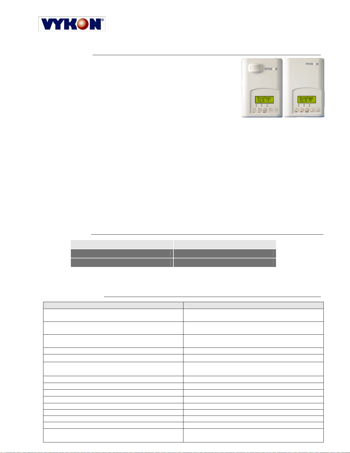
The VT76x7 PI thermostat family is specifically designed for single stage
and multi-stage control of heating/cooling equipment such as rooftop and
self-contained units with humidifier and/or dehumidifier. The product
features an embedded complete humidity solution with an intuitive, menudriven, backlit LCD display that walks users through the programming
steps, making the process extremely simple. Accurate temperature &
relative humidity control is achieved due to the product’s PI time
proportional control algorithm, which virtually eliminates temperature offset
associated with traditional, differential-based thermostats.
All models contain one digital input, which can be set by the user to
monitor filter status, activate a remote temporary occupancy switch, and/or used as a general purpose service
indicator. The two models contain a SPST auxiliary switch, which can be used to control lighting or disable the
economizer function and a discharge air sensor input.
The thermostats are also compatible with the new Vykon PIR cover accessories. Thermostats equipped with
a PIR cover provide advanced active occupancy logic, which will automatically switch occupancy levels from
Occupied to Stand-By and Unoccupied as required by local activity being present or not. This advanced
occupancy functionality provides advantageous energy savings during occupied hours without sacrificing
occupant comfort. All thermostats can be ordered with or without a factory installed PIR cover ( see ordering
notes below ).
The additional following documentation is available:
• VYKONStat PIR Ready VT76xx Series BACnet Integration Guide
• VYKONStat PIR Ready VT6x7 Series LonWorks Integration Guide
• VYKONStat PIR Application Guide
• VYKONStat PIR Cover Assembly Installation Guide
• VYKONStat Wireless Controller Application Guide
Models Available
Application 2 Heat / 2 Cool
Model (programmable) VT7657B5x28(X)
Model (non-programmable) VT7607B5x28(X)
Ordering Information Notes:
- (X) model number represents available communication options: X=none for Stand-alone, X=B for BACnet MS-TP, X=E for Echelon and X=W for
Wireless
- Thermostats can be ordered with a factory installed PIR cover. Please use (5500) extension instead of the (5028) only extension.: Ex. VT7607B5500E.
- Thermostats ordered without a PIR cover can be retrofitted with a separate PIR accessory cover afterwards when required
Features and benefits
Features Benefits
• Advanced occupancy functions ⇒ Through the network or smart local occupancy sensing
• Ready for PIR accessory cover ⇒ Fully integrated advanced occupancy functionality with
a PIR accessory cover
• Embedded humidification sequence (0-10 Vdc output)
⇒ Simplifies installation and reduce installation costs
and dehumidification sequence (dry contact)
• Internal embedded RH sensor ⇒ Eliminates components
• Proportional RH high limit override ⇒ Prevents costly damage due to over-humidification
• Humidity setpoint reset based on outdoor temperature ⇒ Saves energy and prevents window condensation in
colder climates
• PI time proportioning algorithm ⇒ Increased comfort , accuracy, and energy savings
• 1 digital input ⇒ Adds functionality
• Smart fan ⇒ Saves energy during night mode
• Unique configuration key with password protection ⇒ Minimizes parameter tampering
• 6 hour reserve time for clock ⇒ No need to reprogram day/time after power shortage
• Remote outdoor temperature sensor ⇒ Increase flexibility and functionality
• Auxiliary output ⇒ Can be used for lighting and/or economizer override
• Discharge air humidity sensor ( 0-10 Vdc input ) ⇒ Can be used to limit supply RH levels
• Intuitive, menu-driven programming (7 day, 2/4 events -
on programmable models only)
⇒ Can be used for all types of establishments

2
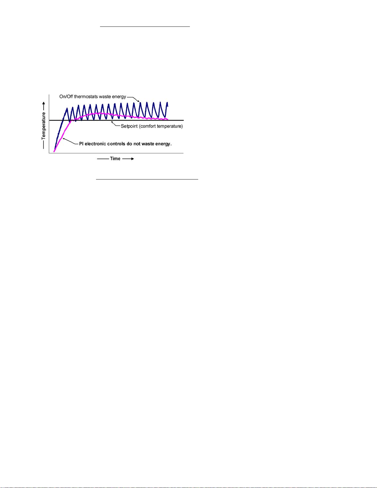
Theory of operation
The VT76x7 uses a Viconics proprietary adaptive logic
algorithm to control the space temperature. This
algorithm controls the heating / air conditioning system
to minimize overshoots while still providing comfort. It
provides exceptional accuracy due to its unique PI
time proportioning control algorithm, which virtually
eliminates temperature offset associated with
traditional, differential-based on/off thermostats.
Fig.2 - On/Off mechanical control vs PI electronic control.
Features overview
• 7 day programmable models, 2 or 4 events
• Gas/oil or electric system compatibility for all type
of applications
• Internal RH sensor and remote RH input with
humidification and dehumidification sequence of
operation embedded
• Remote outdoor sensing capability for added
flexibility
- System mode lock out
- Humidity setpoint reset
• High limit input to prevent over-humidification
• Lockable keypads for tamper proofing. No need for
thermostat guards
• Automatic frost protection to prevents costly freeze
damage
• Anti short cycle and minimum on/off run time
protection. Reduces wear and maximizes life span
of mechanical equipment.
• Programmable digital input for added flexibility. The
input can be programmed as the following:
- None: No function will be associated with the
input
- Service: a backlit flashing Serv
ice alarm will be
displayed on the thermostat LCD screen when
the input is energized. It can be tied in to the AC
unit control card, which provides an alarm in
case of malfunction.
-
Filter: a backlit flashing Filter alarm will be
displayed on the thermostat LCD screen when the
input is energized. It can be tied to a differential
pressure switch that monitor filters
- Rem NSB: remote NSB timer clock input. Will
disable the internal scheduling of the thermostat.
The scheduling will now be set as per the digital
input. The menu part related to scheduling is
disabled and no longer accessible. It provides low
cost setback operation via occupancy sensor or
from a dry contact
- RemOVR: temporary occupancy contact. Disables
all override menu function of the thermostat. . The
override function is now controlled by a manual
remote momentarily closed contact. When
configured in this mode, the input operates in a
toggle mode.
With this function enabled it is now possible to
toggle between unoccupied & occupied setpoints
for the amount of time set by parameter
(TOccTime) temporary occupancy time.
Fan lock: used in conjunction with a local airflow
sensor connected to the input. Locks out the
thermostat heating and cooling action and displays
a local alarm if no air flow is detected 10 seconds
after the fan ( G terminal ) is energized.
• Programmable smart fan operation saves
energy during night mode
• Non volatile EEPROM memory prevents loss of
parameters during power shortage
• Built in default profile set-up for easier start up
and commissioning
• Configurable SPST output relay on
programmable models for lighting, exhaust fan
or fresh air control
• 6 hour typical reserve time for clock in case of
power loss
• 0 to 10 Vdc humidification output
- Built in proportional humidity controller
- Proportional humidity high limit when used
with the analog input for supply humidity
- Automatic humidity setpoint reset when
outside air temperature value is used.
3
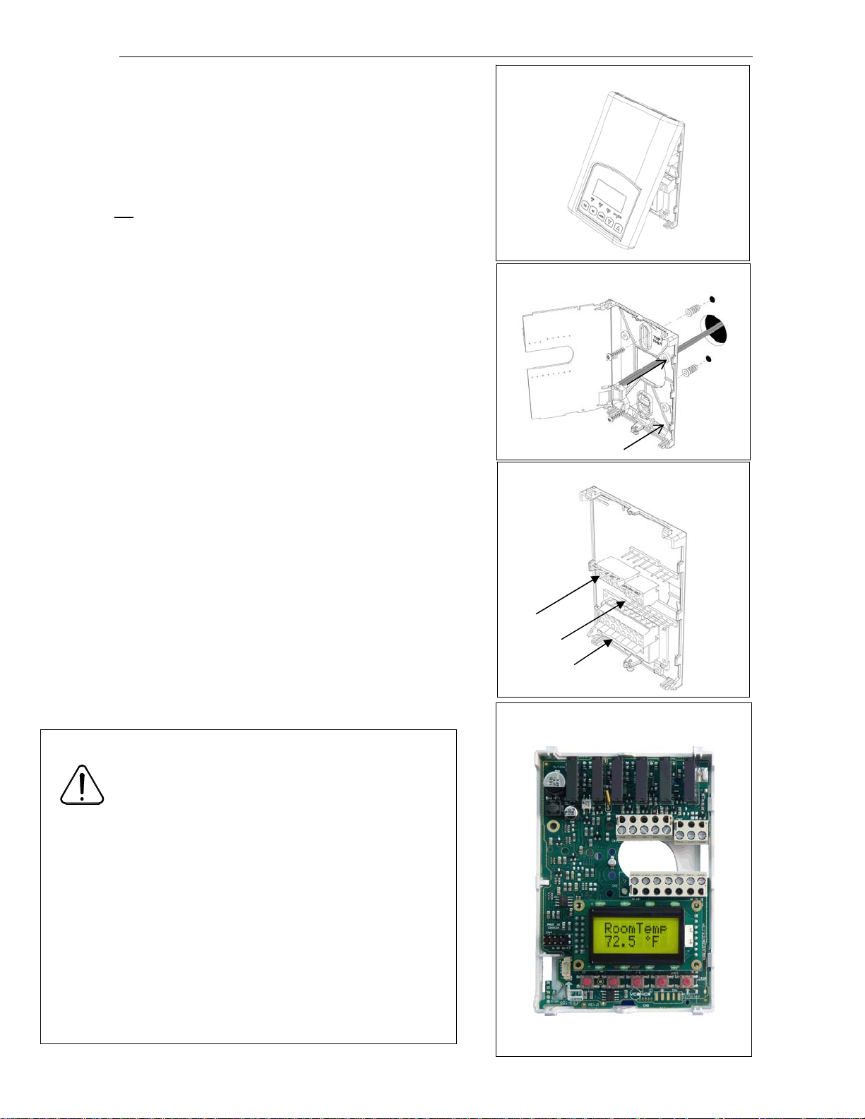
Installation
4
• Remove security screw on the bottom of thermostat cover.
• Open up by pulling on the bottom side of thermostat.
• Remove Assembly and wiring terminals from sticker. (Fig. 3)
• Please note the FCC ID and IC label installed in the cover upon
removal of cover for the wireless products.
A) Location:
1- Should not
be installed on an outside wall.
2- Must be installed away from any heat source.
3- Should not be installed near an air discharge grill.
4- Should not be affected by direct sun radiation.
5- Nothing must restrain vertical air circulation to the thermostat.
B) Installation:
1- Swing open the thermostat PCB to the left by pressing the PCB
locking tabs. (Fig. 4)
2- Pull out cables 6” out of the wall.
3- Wall surface must be flat and clean.
4- Insert cable in the central hole of the base.
5- Align the base and mark the location of the two mounting holes
on the wall. Install proper side of base up.
6- Install anchors in the wall.
7- Insert screws in mounting holes on each side of the base.
(Fig. 4)
8- Gently swing back the circuit board on the base and push on it
until the tabs lock it.
10- Strip each wire 1/4 inch.
11- Insert each wire according to wiring diagram.
13- Gently push back into hole excess wring (Fig. 5)
14- Re-Install wiring terminals in correct location. (Fig. 5)
15- Reinstall the cover (top side first) and gently push back extra
wire length into the hole in the wall.
16- Install security screw.
• If replacing an old thermostat, label the wires before
removal of the old thermostat.
• Electronic controls are static sensitive devices.
Discharge yourself properly before manipulation and
installing the thermostat.
• Short circuit or wrong wiring may permanently damage
the thermostat or the equipment.
• Anti-short cycling can be set to 0 minutes for equipment
that posses their own anti cycling timer. Do not use that
value unless the equipment is equipped with such
internal timer. Failure to do so can damage the
equipment.
• All VT7000 series thermostats are to be used only as
operating controls. Whenever a control failure could
lead to personal injury and/or loss of property, it
becomes the responsibility of the user to add safety
devices and/or alarm system to protect against such
catastrophic failures.
Fig.3
Fig.5
Fig.4
Re-install terminal blocks
Thermostat assembly
(VT7600B5x28 shown)
Fig.6
Wiring identification & screw terminal arrangement
Part Number VT7657B5x28(X) VT7607B5x28(X)
Programmable Yes No
Top left terminal block
Y2 X X
Y1 X X
G X X
RC X X
C X X
Top right terminal block
RH X X
W1 X X
W2 X X
Bottom terminal block
HUM X X
AUX X X
DEHUM X X
DI X X
HS X X
SCOM X X
OS X X
HL X X
5 pole left top connector
Y2
RCGY1
8 pole bottom connector
DE
HUM
AUX
HUM
DI
3 pole left top connector
C
HS OS
W1RH
S
COM
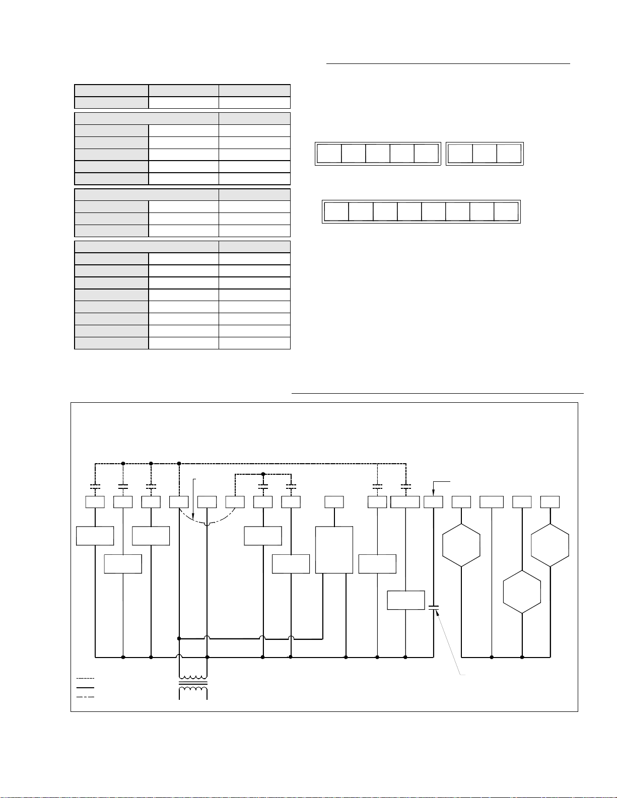
Detailed wiring diagrams for selected models
VT76X7B5X28(X)
2 Heat / 2 Cool / Humidifier & Dehumidifier Outputs / Programmable & Non-Programmable
Jumper J1
Y2 Y1
See note 1
(previous
page)
RCG C
W1RH W2
HUM AU
DeHum
Digital Input
DI HS
Scom
W2
HL
OS
5
HL
Cool
Stage 2
Cool
Stage 1
Thermostat internal wiring
System wiring
Jumper J1
Fan
24 Vac
T1
Heat
Stage 1
Heat
Stage 2
0-10 Vdc
Com24V
Auxiliary
Output
Dehum
Output
0-10 Vdc
Remote
Humidity
Sensor
Field contact
Remote
Outdoor
Sensor
0-10 Vdc
High Limit
Humidity
Sensor
Wiring notes:
Note 1: If the same power source is used for the heating stages, install jumper across RC & RH. Maximum current is 2.0
amps.
Note 2: If auxiliary output is used to toggle occupancy of the electronic control card inside the equipment, configure the
relay parameter (Aux cont ) to the N.O. setting. A second relay can be added for additional functionality of the
occupancy output.
Note 3: Humidifier output uses a half bridge rectifier. Reference of the control signal is the common of the power supply of
the thermostat. (terminal C)
Note 4: Electromechanical contact are to be used with the digital input. Electronic triacs cannot be used as mean of
switching for the input. The switched leg to the input for the input to activate is terminal C ( common )
Note 5: The transformer of the unit provides power to the thermostat and the additional loads that will be wired to the
thermostat.
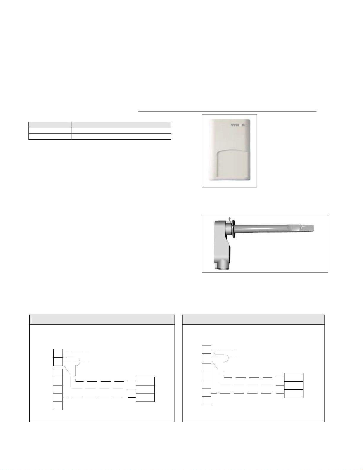
Remote humidity sensor accessories
Model no. Description
VH2020W1028 Wall mounted humidity sensor
VH2020D1028 Duct mounted humidity sensor
VH2020W1028, remote wall mounted room humidity sensor.
This sensor can be used for:
• Remote return or room air humidity sensing with the
sensor mounted on the wall.
Fig.7– VH2020W1028
Remote wall mounted sensor
VH2020D1028, remote duct mounted humidity sensor c/w
junction box.
This sensor can be used for:
• Remote return air humidity sensing with the sensor
mounted on the return air duct.
• Supply air humidity sensor used as a high limit
protection.
6
Wiring example of remote room humidity sensor:
VT76x7 Series
Thermostat
C
RC
HL
OS
Scom
HS
DI
24 Vac Power
To Thermostat
VH2020W1000
Remote wiring
1
Common
2
Power
0-10 Vdc
4
Fig.9 – VH2020D1028
Remote duct mounted humidity sensor
Wiring example of duct humidity sensor:
VT76x7 Series
Thermostat
C
RC
HL
OS
Scom
HS
DI
Valid for both hight limit sensor (HL) or
main remote humidity sensor (HS) connections
24 Vac Power
To Thermostat
VH2020D1000
Remote wiring
1
Common
2
Power
0-10 Vdc
4
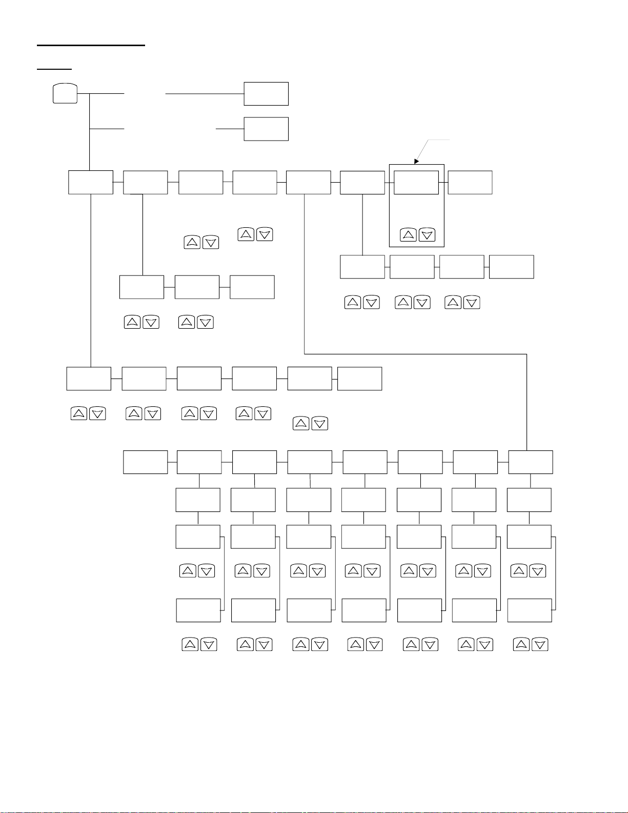
User menu flow chart:
NOTE:
Prompts may not all be present depending on model selected
MENU
If statu s is:
Unoccupied
7
Over ri de
schd Y/ N
If statu s is:
Temporary Occupied Time,
Occupied hold or
Resume
schd Y/ N
Unoccupied hold
Temperat
set ? Y/ N
Humi d i t y
set ? Y/ N
Sys mode
set ? Y/ N
Off
Heat
Cool
Fan mode
set ? Y/ N
On
Smart
Auto
Auto
Dehumi di
set ? Y/ N
Humi d i f i
set ? Y/ N
Exi t ?
Y/ N
RH% RH%
Cooling
set ? Y/ N
Heat i ng
set ? Y/ N
Unocc CL
set ? Y/ N
Unocc HT
set ? Y/ N
Temperature Temperature Temperature Temperature
Schedul e
set ? Y/ N
°F/°C
set ? Y/ N
°C
°F
Cl oc k
set ? Y/ N
Ti me
set ? Y/ N
Time
Exi t ?
Y/ N
Schedul e
hol d Y/ N
Resume
Occ Hold
Uno Hold
Da y
set ? Y/ N
Day
On stand-alone
models only
Exi t ?
Y/ N
12/ 24hrs
set ? Y/ N
12 / 24
Exi t ?
Y/ N
Exi t ?
Y/ N
Sunday
set ? Y/ N
Occupi ed
day? Y/ N
Occupi ed
12: 00 pm
Time
Unoccup
12: 00 pm
Time
Sat ur da y
set ? Y/ N
Occupi ed
day? Y/ N
Occupi ed
12: 00 pm
Time
Unoccup
12: 00 pm
Time
Fr i da y
set ? Y/ N
Occupi ed
day? Y/ N
Occupi ed
12: 00 pm
Time
Unoccup
12: 00 pm
Time
Thur sday
set ? Y/ N
Oc cupi e d
day? Y/ N
Oc cupi e d
12: 00 pm
Time
Unoccup
12: 00 pm
Time
We dnesda
set ? Y/ N
Occupi ed
day? Y/ N
Occupi ed
12: 00 pm
Time
Unoccup
12: 00 pm
Time
Tuesday
set ? Y/ N
Occupi ed
day? Y/ N
Occupi ed
12: 00 pm
Time
Unoccup
12: 00 pm
Time
Monday
set ? Y/ N
Occupi ed
day? Y/ N
Occupi ed
12: 00 pm
Time
Unoccup
12: 00 pm
Time
Programming and status display instructions
1. Status display
The thermostat features a two-line, eight-character display. There is a low-level backlit level that is always active and can only
be seen at night. When left unattended, the thermostat has an auto scrolling display that shows the actual status of the
system. Each item is scrolled one by one with the backlighting off. Pressing any key will cause the backlit to come on.
Sequence of auto-scroll status display:
Room Temp &
Humidity
x.x °C or °F Monday Sys mode Occupied Outdoor Service
xx % RH 12.00 AM auto x.x °C or°F
If humidity display is
enabled
RoomTemp
x.x °C or °F
If humidity display is not
enabled
Clock status System mode Schedule status
Sys mode
off
Sys mode
heat
Sys mode
cool
Occupied
hold
Unoccup
Unoccup
hold
Override
Outdoor
temperature
Frost ON
SetClock
Filter
Fan lock
Alarms
Manual scroll of each menu item is achieved by pressing the Yes (scroll) key repetitively. The last item viewed will be shown on the
display for 30 seconds before returning to automatic scrolling. Temperature is automatically updated when scrolling is held.
Outdoor air temperature display is only enabled when outdoor air temperature sensor is connected or a network value is
received.
• A maximum range status display of 50 °C (122 °F) indicates a shorted sensor. Associated functions, such as mode lockouts
are automatically disabled.
• A minimum range status -40 °C (-40 °F) is not displayed and indicates a opened sensor or a sensor not connected.
Associated functions, such as mode lockouts are automatically disabled.
If alarms are detected, they will automatically be displayed at the end of the status display scroll. During an alarm message
display, the backlit screen will light up at the same time as the message and shut off during the rest of the status display. Two
alarms maximum can appear at any given time. The priority for the alarms is as follows:
Frost ON
SetClock
Service
Filter
Fan lock
Indicates that the heating is energized by the low limit frost protection room temperature setpoint 5.6 °C (42 °F )
Indicates that the clock needs to be reset. There has been a power failure which has lasted longer than 6 hours
Indicates that there is a service alarm as per one of the programmable digital input (DI1 or DI2)
Indicates that the filters are dirty as per one of the programmable digital input (DI1 or DI2)
Indicates that the heating and cooling action are locked out due to a defective fan operation
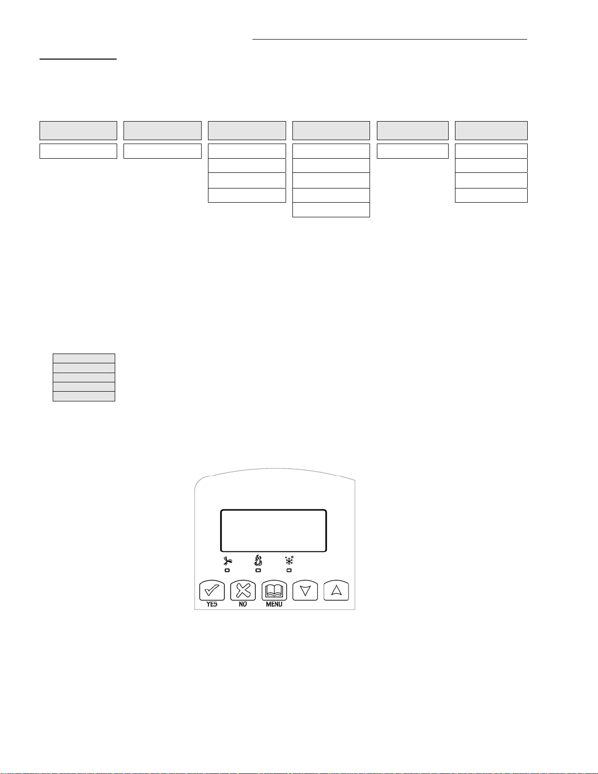
Three status LEDs on the thermostat cover are used to indicate the status of the fan, a call for heat, or a call for cooling.
• When the fan is on, the FAN LED will illuminate.
• When heating is on, the HEAT LED will illuminate.
• When cooling is on, the COOL LED will illuminate.
Fig.10 – VT7657 and VT7607 cover
8
 Loading...