

Page 1

Artisan Technology Group is your source for quality
new and certied-used/pre-owned equipment
• FAST SHIPPING AND
DELIVERY
• TENS OF THOUSANDS OF
IN-STOCK ITEMS
• EQUIPMENT DEMOS
• HUNDREDS OF
MANUFACTURERS
SUPPORTED
• LEASING/MONTHLY
RENTALS
• ITAR CERTIFIED
SECURE ASSET SOLUTIONS
SERVICE CENTER REPAIRS
Experienced engineers and technicians on staff
at our full-service, in-house repair center
Instra
Remotely inspect equipment before purchasing with
our interactive website at www.instraview.com
Contact us: (888) 88-SOURCE | [email protected] | www.artisantg.com
SM
REMOTE INSPECTION
View
WE BUY USED EQUIPMENT
Sell your excess, underutilized, and idle used equipment
We also offer credit for buy-backs and trade-ins
www.artisantg.com/WeBuyEquipment
LOOKING FOR MORE INFORMATION?
Visit us on the web at www.artisantg.com for more
information on price quotations, drivers, technical
specications, manuals, and documentation
Page 2

EX2500
LXI-VXI SLOT 0 INTERFACE
QUICK START GUIDE
P/N: 82-0115-001
Rev: May 23, 2006
VXI Technology, Inc.
2031 Main Street
Irvine, CA 92614-6509
(949) 955-1894
Page 3

VXI Technology, Inc.
2 EX2500 Preface
Page 4

www.vxitech.com
TABLE OF CONTENTS
INTRODUCTION
Certification..........................................................................................................................................................4
Warranty...............................................................................................................................................................4
Limitation of Warranty.........................................................................................................................................4
Restricted Rights Legend......................................................................................................................................4
DECLARATION OF CONFORMITY...............................................................................................................................5
GENERAL SAFETY INSTRUCTIONS.............................................................................................................................6
Terms and Symbols..............................................................................................................................................6
Warnings...............................................................................................................................................................7
SUPPORT RESOURCES ...............................................................................................................................................8
SECTION 1....................................................................................................................................................................9
OVERVIEW................................................................................................................................................................9
Introduction ..........................................................................................................................................................9
VISA Requirements..............................................................................................................................................9
Agilent VISA as Primary VISA Installation Path...........................................................................................9
Agilent VISA as Secondary VISA Installation Path .......................................................................................9
AGILENT VISA AS PRIMARY VISA ........................................................................................................................10
VISA Installation................................................................................................................................................10
EX2500 Driver Installation.................................................................................................................................14
Add the EX2500 Interface to Agilent VISA.......................................................................................................16
AGILENT VISA AS SECONDARY VISA ...................................................................................................................21
VISA Installation................................................................................................................................................21
EX2500 Driver Installation.................................................................................................................................25
Configure NI-VISA for Use with Agilent VISA................................................................................................27
Add the EX2500 Interface to Agilent VISA.......................................................................................................28
Web Interface .....................................................................................................................................................33
Front Panel Indicators.........................................................................................................................................34
EX2500 Preface 3
Page 5

VXI Technology, Inc.
CERTIFICATION
VXI Technology, Inc. (VTI) certifies that this product met its published specifications at the time of shipment from
the factory. VTI further certifies that its calibration measurements are traceable to the United States National
Institute of Standards and Technology (formerly National Bureau of Standards), to the extent allowed by that
organization’s calibration facility, and to the calibration facilities of other International Standards Organization
members.
WARRANTY
The product referred to herein is warranted against defects in material and workmanship for a period of three years
from the receipt date of the product at customer’s facility. The sole and exclusive remedy for breach of any warranty
concerning these goods shall be repair or replacement of defective parts, or a refund of the purchase price, to be
determined at the option of VTI.
For warranty service or repair, this product must be returned to a VXI Technology authorized service center. The
product shall be shipped prepaid to VTI and VTI shall prepay all returns of the product to the buyer. However, the
buyer shall pay all shipping charges, duties, and taxes for products returned to VTI from another country.
VTI warrants that its software and firmware designated by VTI for use with a product will execute its programming
when properly installed on that product. VTI does not however warrant that the operation of the product, or
software, or firmware will be uninterrupted or error free.
LIMITATION OF WARRANTY
The warranty shall not apply to defects resulting from improper or inadequate maintenance by the buyer, buyersupplied products or interfacing, unauthorized modification or misuse, operation outside the environmental
specifications for the product, or improper site preparation or maintenance.
VXI Technology, Inc. shall not be liable for injury to property other than the goods themselves. Other than the
limited warranty stated above, VXI Technology, Inc. makes no other warranties, express or implied, with respect to
the quality of product beyond the description of the goods on the face of the contract. VTI specifically disclaims the
implied warranties of merchantability and fitness for a particular purpose.
RESTRICTED RIGHTS LEGEND
Use, duplication, or disclosure by the Government is subject to restrictions as set forth in subdivision (b)(3)(ii) of the
Rights in Technical Data and Computer Software clause in DFARS 252.227-7013.
VXI Technology, Inc.
2031 Main Street
Irvine, CA 92614-6509 U.S.A.
4 EX2500 Preface
Page 6
www.vxitech.com
D ECLARATION OF C ONFORMITY
Declaration of Conformity According to ISO/IEC Guide 22 and EN 45014
ANUFACTURER’S NAME VXI Technology, Inc.
M
ANUFACTURER’S ADDRESS 2031 Main Street
M
Irvine, California 92614-6509
RODUCT NAME LXI-VXI Slot 0
P
ODEL NUMBER(S) EX2500
M
RODUCT OPTIONS All
P
RODUCT CONFIGURATIONS All
P
VXI Technology, Inc. declares that the aforementioned product conforms to the requirements of
the Low Voltage Directive 73/23/EEC and the EMC Directive 89/366/EEC (inclusive 93/68/EEC)
and carries the “CE” mark accordingly. The product has been designed and manufactured
according to the following specifications:
AFETY EN61010 (2001)
S
EMC EN61326 (1997 w/A1:98) Class A
CISPR 22 (1997) Class A
VCCI (April 2000) Class A
ICES-003 Class A (ANSI C63.4 1992)
AS/NZS 3548 (w/A1 & A2:97) Class A
FCC Part 15 Subpart B Class A
EN 61010-1:2001
I hereby declare that the aforementioned product has been designed to be in compliance with the relevant sections
of the specifications listed above as well as complying with all essential requirements of the Low Voltage Directive.
May 2006
Steve Mauga, QA Manager
EX2500 Preface 5
Page 7
Review the following safety precautions to avoid bodily injury and/or damage to the product.
These precautions must be observed during all phases of operation or service of this product.
Failure to comply with these precautions, or with specific warnings elsewhere in this manual,
violates safety standards of design, manufacture, and intended use of the product.
Service should only be performed by qualified personnel.
TERMS AND SYMBOLS
These terms may appear in this manual:
WARNING
CAUTION
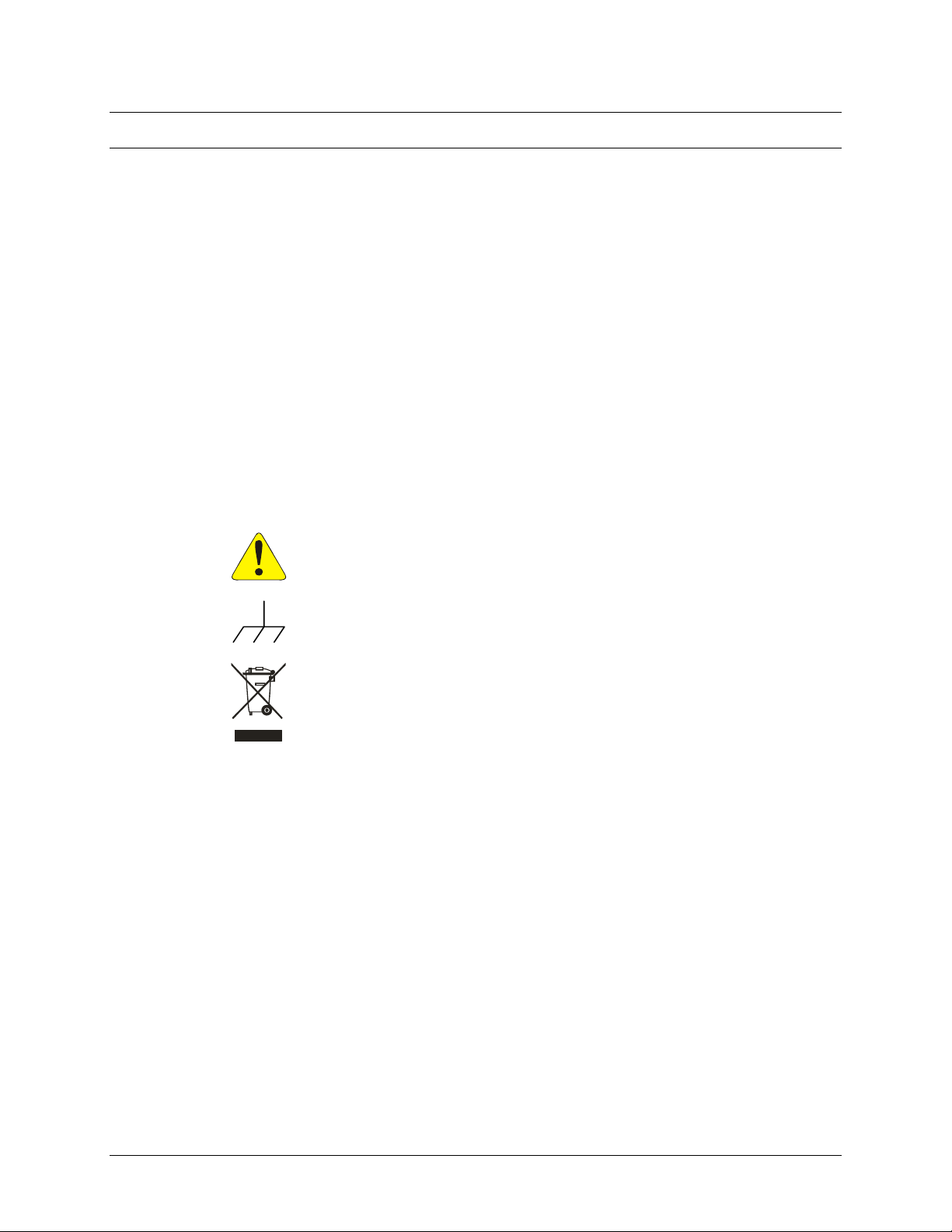
These symbols may appear on the product:
VXI Technology, Inc.
GENERAL SAFETY INSTRUCTIONS
Indicates that a procedure or condition may cause bodily injury or death.
Indicates that a procedure or condition could possibly cause damage to
equipment or loss of data.
ATTENTION - Important safety instructions
Frame or chassis ground
Indicates that the product was manufactured after August 13, 2005. This mark is
placed in accordance with EN 50419, Marking of electrical and electronic
equipment in accordance with Article 11(2) of Directive 2002/96/EC (WEEE).
End-of-life product can be returned to VTI by obtaining an RMA number. Fees
for take-back and recycling will apply if not prohibited by national law.
6 EX2500 Preface
Page 8

www.vxitech.com
WARNINGS
Follow these precautions to avoid injury or damage to the product:
Connect Cables Properly
Avoid Electric Shock
Ground the Product
Operating Conditions
Class 1 Laser Product
Improper Use
To avoid damage and potential loss of phone service, ensure that
the RJ-45 connector on the front panel of the EX2500 is not
connected to a standard telephone jack. This should only be
connected to a network interface card, network router, or network
hub.
To avoid electric shock or fire hazard, do not operate this product
with the covers removed. Do not connect or disconnect any cable,
probes, test leads, etc. while they are connected to a voltage source.
Remove all power and unplug unit before performing any service.
Service should only be performed by qualified personnel.
This product is grounded through the grounding conductor of the
power cord. To avoid electric shock, the grounding conductor must
be connected to earth ground.
To avoid injury, electric shock or fire hazard:
- Do not operate in wet or damp conditions.
- Do not operate in an explosive atmosphere.
- Operate or store only in specified temperature range.
- Provide proper clearance for product ventilation to prevent
overheating.
- DO NOT operate if any damage to this product is suspected.
Product should be inspected or serviced only by qualified
personnel.
The SFP module in this instrument is a Class 1 Laser device. Do not
attempt to disassemble this module. In the interest of safety, this
equipment should only be serviced by an authorized VXI
Technology representative. Please observe the following safety
precautions:
• Do not open the unit
• If the unit requires service, contact VXI Technology
• Ensure proper use by reading and following the
instructions carefully
• Do not attempt to make any adjustments to the unit
The operator of this instrument is advised that if the equipment is
used in a manner not specified in this manual, the protection
provided by the equipment may be impaired.
Conformity is checked by inspection.
EX2500 Preface 7
Page 9

VXI Technology, Inc.
SUPPORT RESOURCES
Support resources for this product are available on the Internet an d at VXI Technology customer
support centers.
VXI Technology
World Headquarters
VXI Technology, Inc.
2031 Main Street
Irvine, CA 92614-6509
Phone: (949) 955-1894
Fax: (949) 955-3041
VXI Technology
Cleveland Instrument Division
5425 Warner Road
Suite 13
Valley View, OH 44125
Phone: (216) 447-8950
Fax: (216) 447-8951
VXI Technology
Lake Stevens Instrument Division
VXI Technology, Inc.
1924 - 203 Bickford
Snohomish, WA 98290
Phone: (425) 212-2285
Fax: (425) 212-2289
Technical Support
Phone: (949) 955-1894
Fax: (949) 955-3041
E-mail:
Visit
http://www.vxitech.com for worldwide support sites and service plan information.
8 EX2500 Preface
Page 10

www.vxitech.com
SECTION 1
OVERVIEW
INTRODUCTION
The EX2500 driver was written to be used with Agilent®VISA and, therefore, requires this
software to be installed to function properly. Two software installation paths should be considered
by users when installing the required EX2500 software:
• Use with Agilent VISA software, where Agilent VISA is installed as the primary VISA.
• Use with existing National Instruments
VISA to be installed as the secondary VISA and NI-VISA to be configured properly to
support Agilent VISA.
NOTE The screenshots provided in this section were captured on a Windows®XP® system using specific
VISA (Virtual Instrument Software Architecture) installations. As such, it is possible that the
images provided in this guide may not be identical to the images seen during a specific
installation.
©
VISA (NI-VISA) software, which requires Agilent
VISA REQUIREMENTS
In order to work properly in a test system, the EX2500 requires Agilent VISA to be installed on
the host PC. Agilent VISA may be installed as either the primary VISA, or may be installed
secondary to NI-VISA. The EX2500 is compatible with the following VISA software revisions:
1) Agilent VISA Revision 14.1 or la t er
2) NI-VISA Revision 2.6 or later for guaranteed operation (VXI Technology, Inc., however,
recommends using revision 3.4 or later)
Agilent VISA as Primary VISA Installation Path
If Agilent VISA revision 14.1 or later is installed on the PC that will be co nnected to the EX25 00,
go to page
install revision 14.1. It is recommended that previous versions of Agilent VISA be removed before
installing revision 14.1.
14. If a different version of Agilent VISA is installed on the host PC, go to page 10 to
Agilent VISA as Secondary VISA Installation Path
If NI-VISA revision 2.6 or later is installed on the host PC, go to page 21. If the version of
NI-VISA installed on the host PC is lower than revision 2.6, please install an appropriate version
of NI-VISA and then go to page
EX2500 Quick Start Guide 9
21.
Page 11
AGILENT VISA AS PRIMARY VISA
VISA INSTALLATION
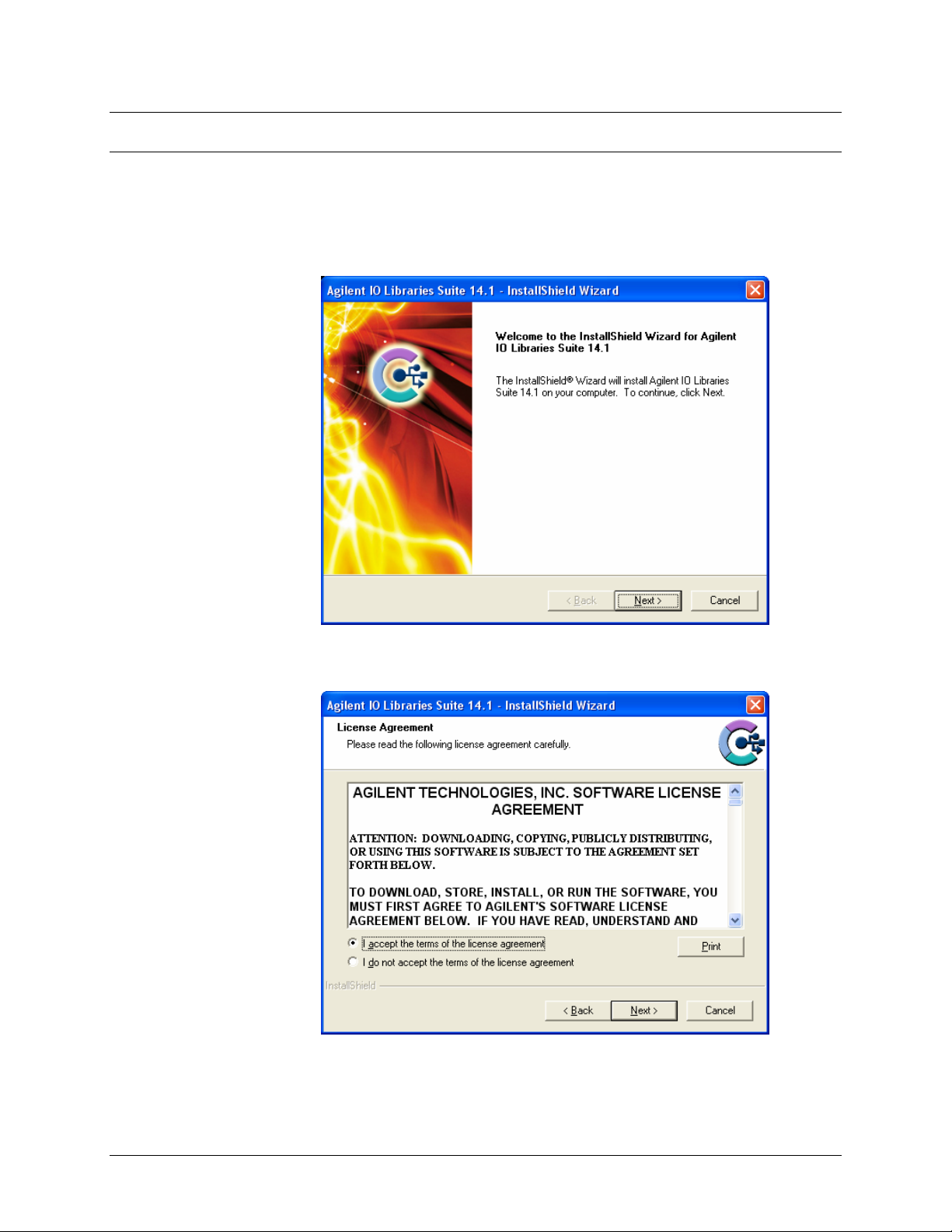
1) Start installation of Agilent VISA. From the VXI Technology, Inc. Distribution CD, run the
program iolibs_suite_14_1_8016_0.exe (or later). At the Welcome screen, click the Next
button.
VXI Technology, Inc.
2) At the License Agreement dialog box, click on the “accept” radio button to accept the license
agreement, and then click Next to continue. If this is not done, installation will cease.
10 EX2500 Quick Start Guide
Page 12
www.vxitech.com
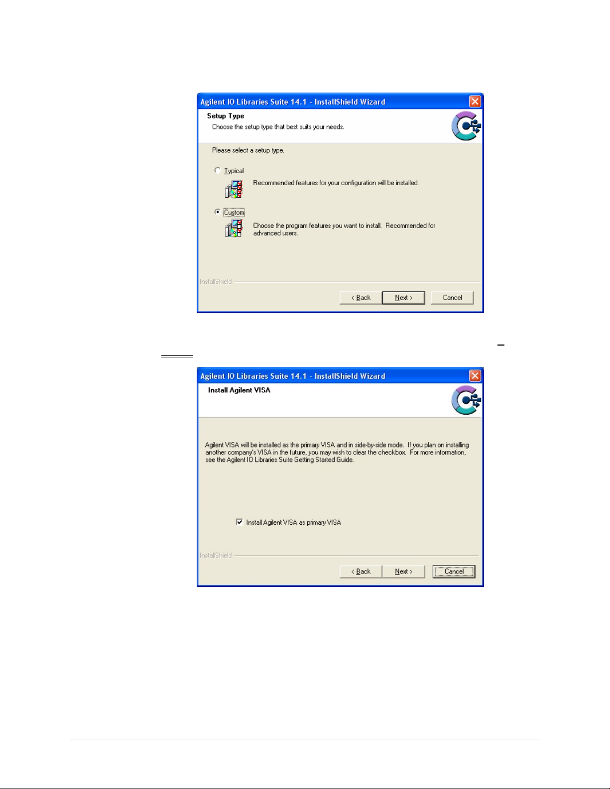
3) At the Setup Type dialog box, select the “Custom” radio button, then click the Next button.
4) At the Install Agilent VISA dialog box, a prompt appears asking if Agilent VISA will be
installed as the primary VISA. Ensure that “Install Agilent VISA as primary VISA” is
selected, and then click the Next button.
EX2500 Quick Start Guide 11
Page 13
VXI Technology, Inc.
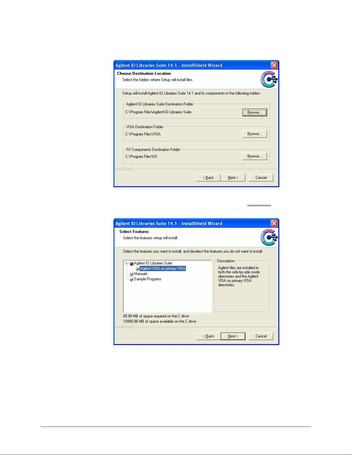
5) No changes are required at the Choose Destination Location dialog box. Click the Next
button to continue.
6) At the Select Features dialog box, a summary of features that will be installed is provided.
Make certain that the “Agilent VISA as primary VISA” check box is selected
. Once this has
been verified, click the Next button to continue.
12 EX2500 Quick Start Guide
Page 14
www.vxitech.com
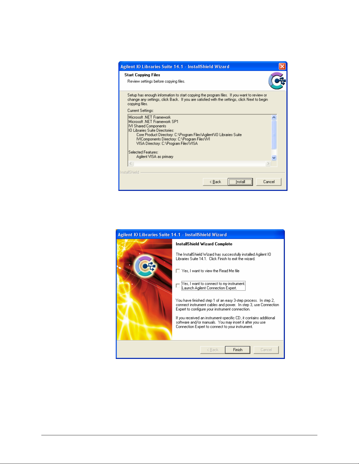
7) Next, the Start Copying Files dialog box will appear. To begin software installation, click the
Install button.
8) Once Agilent VISA installation is complete, the InstallShield Wizard Complete dialog box
will appear. As the EX2500 driver must be installed before the Agilent Connection Expert can
be used, ensure that both check boxes on this dialog box are not selected. Click the Finish
button to complete VISA installation.
EX2500 Quick Start Guide 13
Page 15
EX2500 DRIVER INSTALLATION
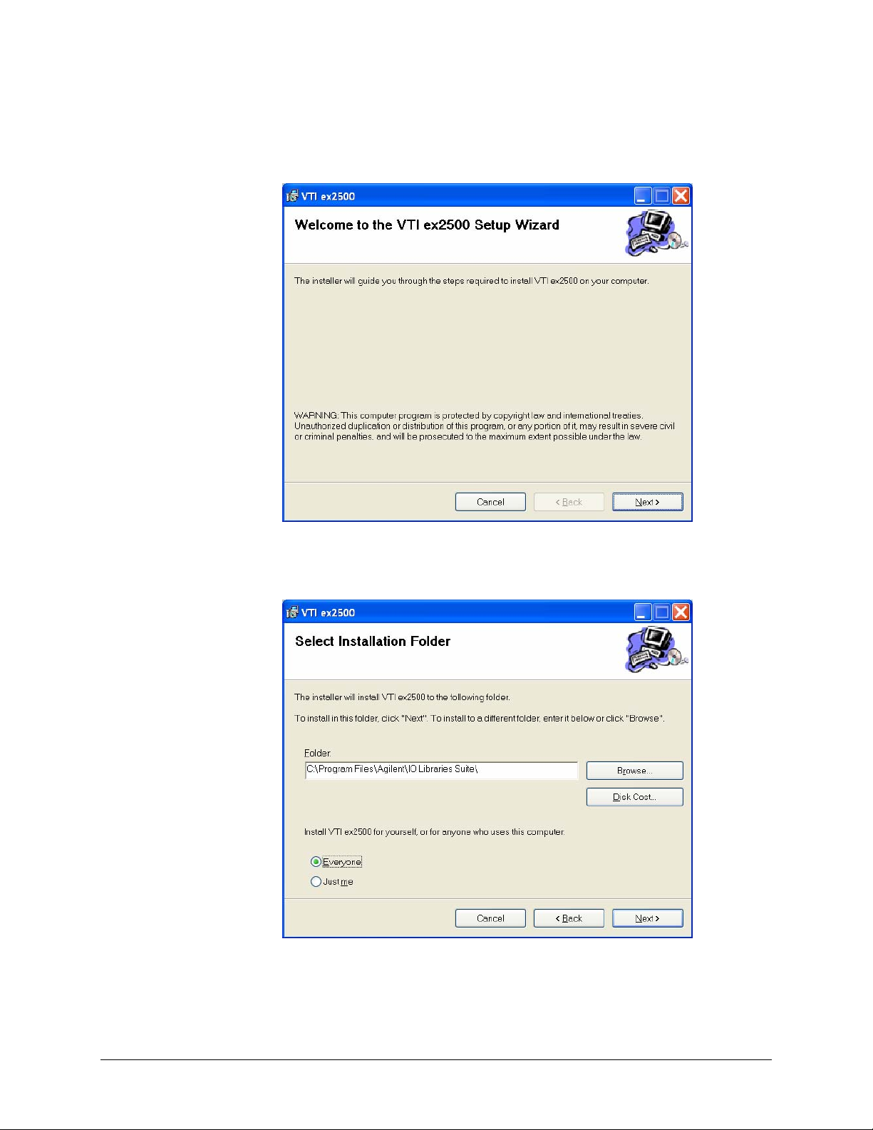
1) From the VXIplug&play Drivers and Product Manuals CD, run the program
EX2500_Driver_R1p0p0.msi (or later). At the Welcome dialog box, click the Next button.
VXI Technology, Inc.
2) From the Select Installation Folder dialog box, select an appropriate radio button according
to host PC demands. No changes are required in the Folder field. Click the Next button to
proceed.
14 EX2500 Quick Start Guide
Page 16
www.vxitech.com
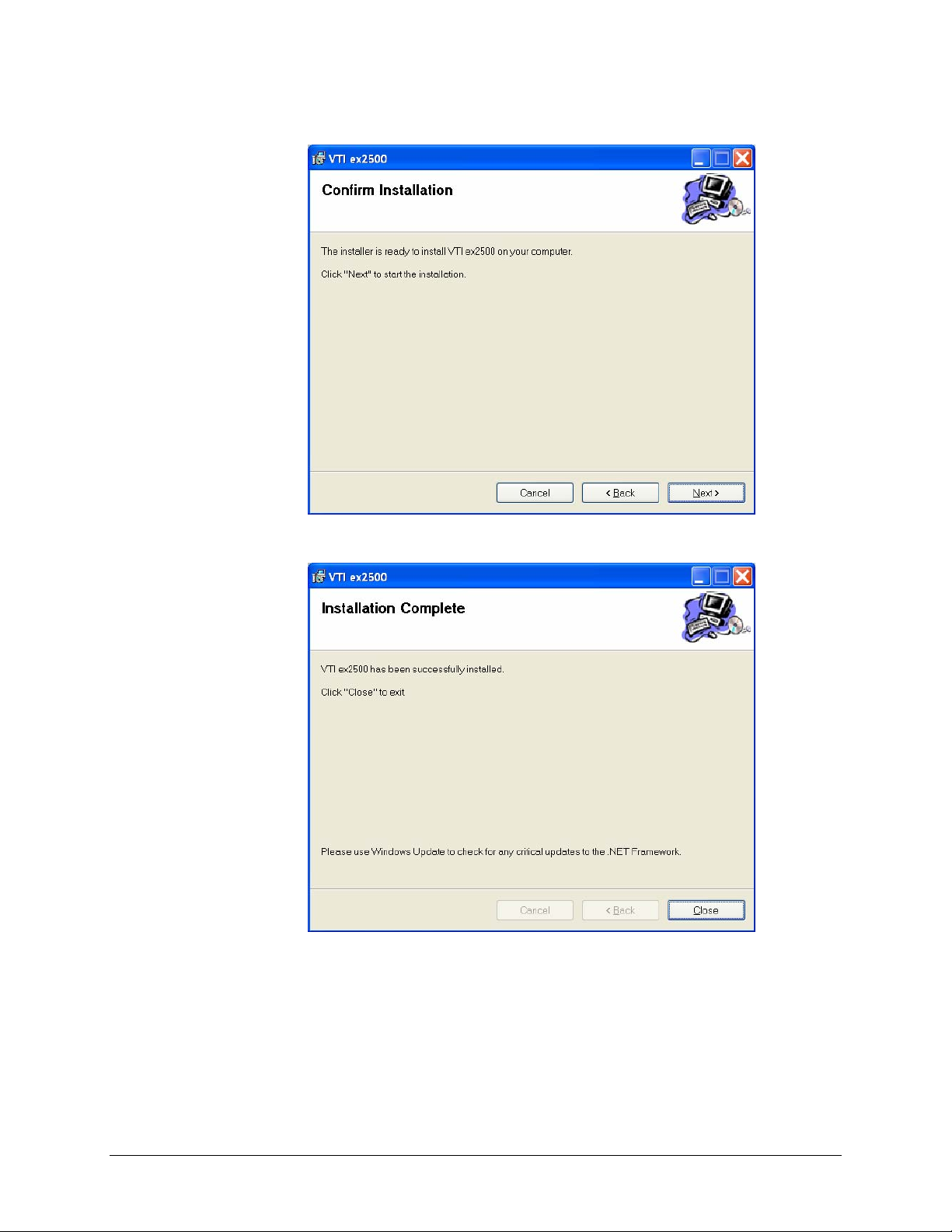
3) At the Confirm Installation dialog box, click the Next button.
4) Click the close button and continue to
Add the EX2500 Interface to Agilent VISA.
EX2500 Quick Start Guide 15
Page 17
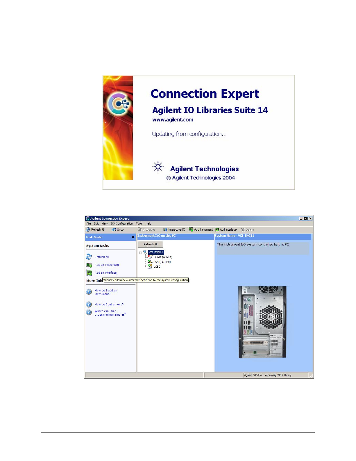
ADD THE EX2500 INTERFACE TO AGILENT VISA
1) Open Agilent’s Connection Expert© from the Start Menu via the path Start > All Programs >
Agilent IO Libraries Suite > Agilent Connection Expert.
VXI Technology, Inc.
2) From the Connection Expert main window, click the “Add an interface” link in the Task
Guide field.
16 EX2500 Quick Start Guide
Page 18
www.vxitech.com
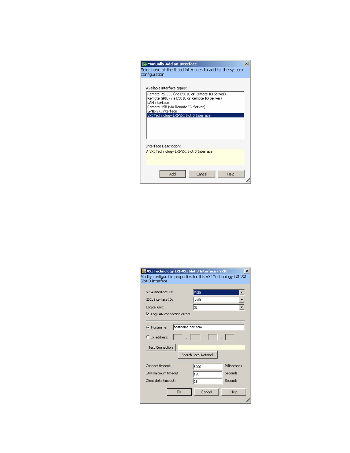
3) From the Manually Add an Interface dialog box, select “VXI Technology LXI-VXI Slot 0
Interface” from the list and then click Add.
4) A configuration window will appear where a module is assigned a VISA interface ID which is
then mapped to the device’s IP address. There must be a unique VISA interface ID for each
interface defined in a system. NOTE: if NI-VISA is installed, a VISA Interface ID other than
VXI0 must be assigned, as NI-VISA reserves VXI0 for MXI-2 devices (whether a MXI-2
device is installed or not). To automatically search for the module, click on Search Local
Network on the configuration window. This software utility will search for EX2500s. If the
EX2500 is connected directly to the Network Interface Card (NIC) in the host system, the
EX2500 software will automatically assign a link-local IP address based on the MAC address
of the module. If the module is connected to a LAN that is DHCP enabled, the DHCP server
will assign an IP address to the module. To determine if a LAN is DHCP enabled, please
contact your Network Administrator.
EX2500 Quick Start Guide 17
Page 19
VXI Technology, Inc.
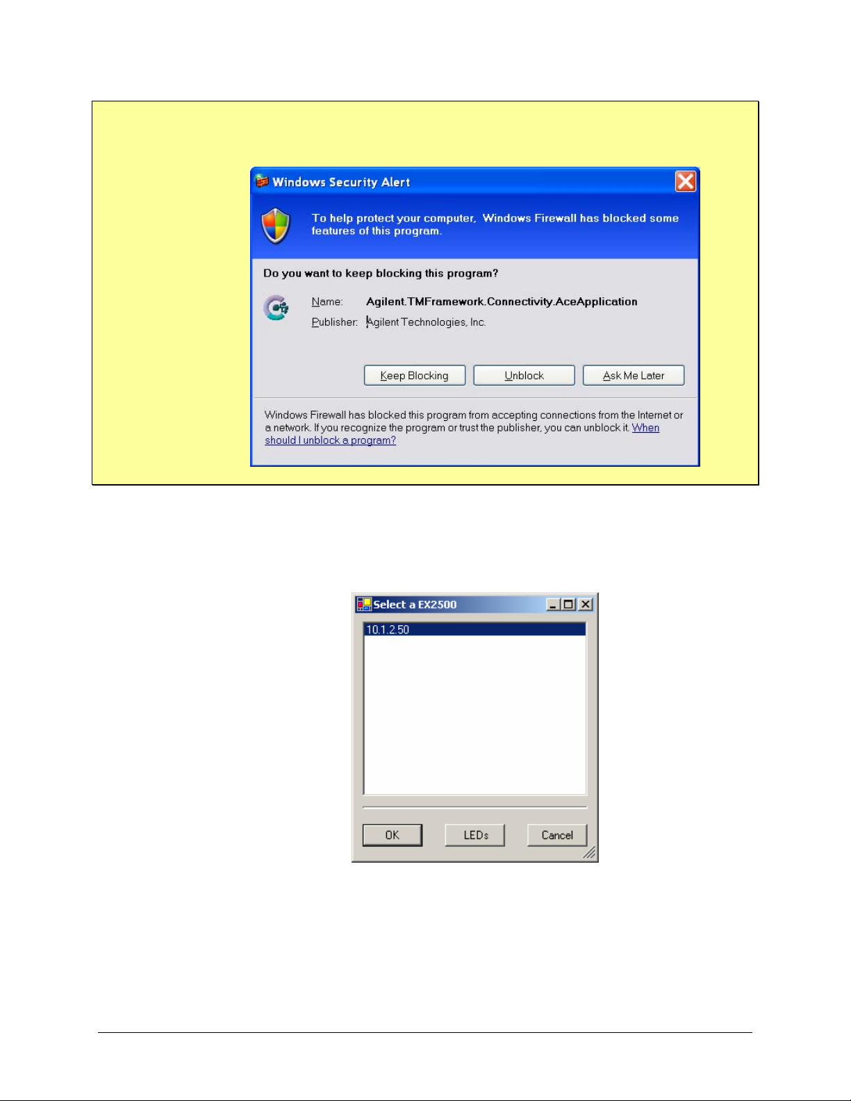
NOTE On PCs running Windows XP, the Windows Firewall utility may try to block Connection
Expert from connecting to the EX2500. To avoid blocking multiple connections, it may be
desirable to turn off Windows Firewall. Refer to Wind o ws Help f or more inf ormation.
5) Connection Expert will display the IP address of all EX2500s discovered on the network.
Clicking LEDs runs a test on the LEDs of the highlighted EX2500 causing the Link Status
LEDs to blink in a “leap-frog pattern”. An additional dialog box will appear asking if this is
the correct module. It this is the module of interest, click OK to establish the highlighted
EX2500 as the target module.
18 EX2500 Quick Start Guide
Page 20
www.vxitech.com
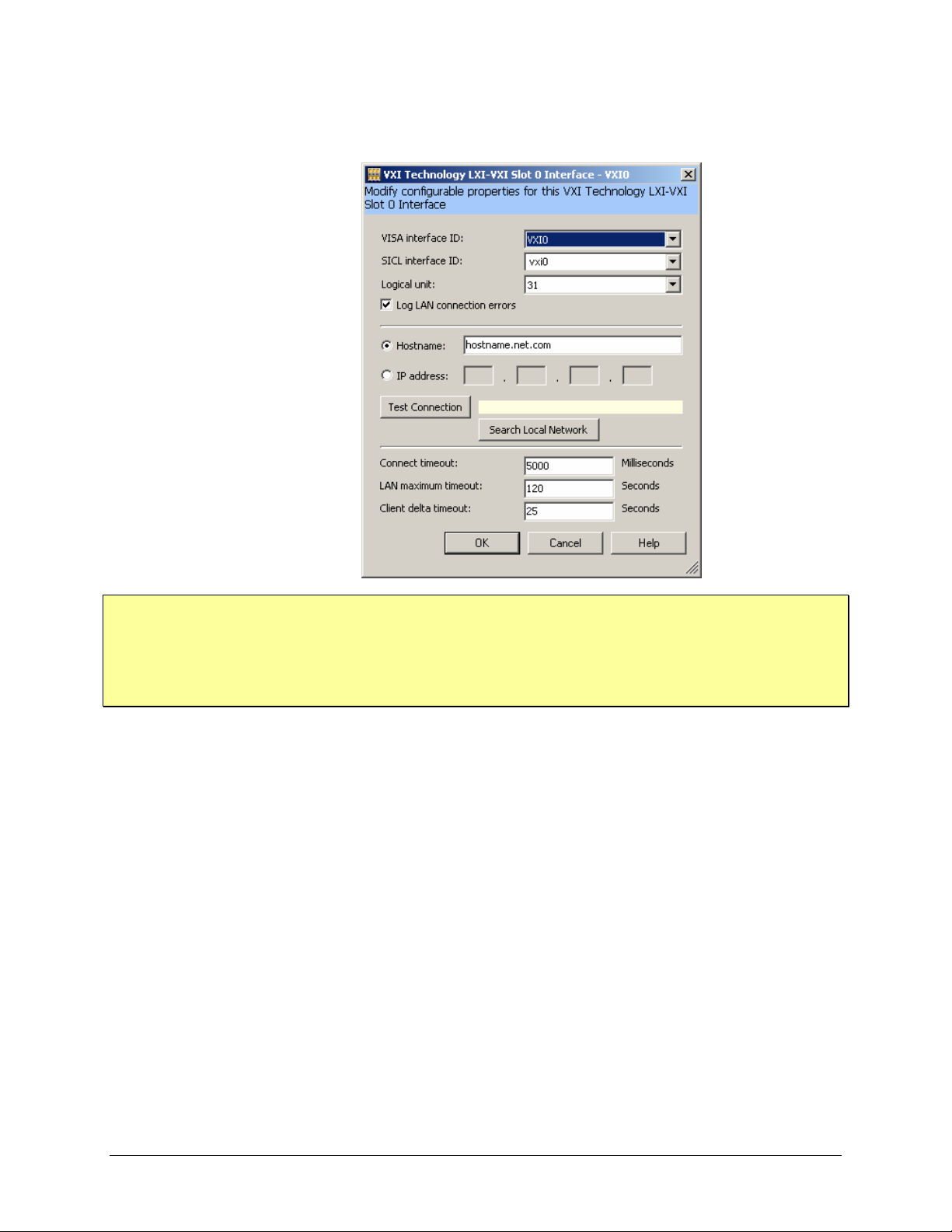
The IP address field will now contain the IP of the target EX2500. Clicking OK assigns the
VISA interface ID shown to the target EX2500.
NOTE This process should be repeated for each EX2500 included in a test syste m. It is imperative that
each EX2500 module have a unique VISA interface ID.
If a MXI-2 interface will be installed into a mainframe after an EX2500 has been installed, the
EX2500 should have its VISA interface ID reassigned if its ID is VXI0. If this is not done, it will
cause the I/O software to perform improperly and make accessing the EX2500 impossible.
EX2500 Quick Start Guide 19
Page 21
VXI Technology, Inc.
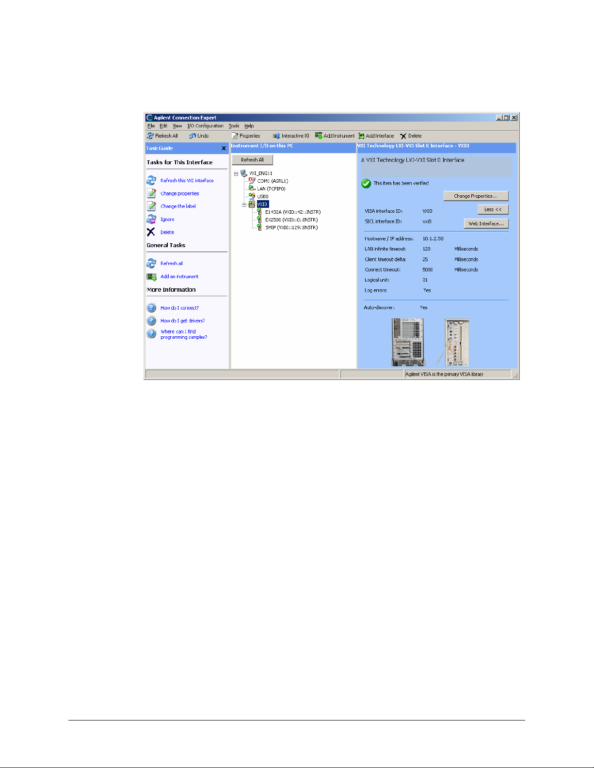
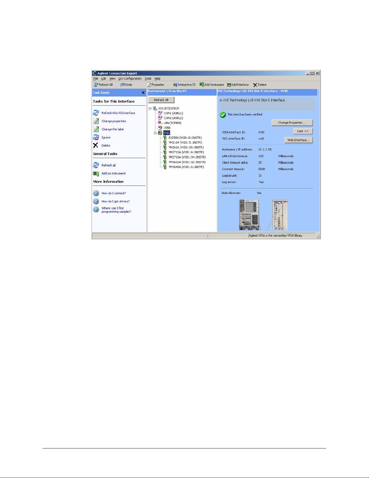
6) The Slot 0 interface to the EX2500 should now appear in the Instrument I/O on this PC
field. The adjacent field contains buttons that allow for EX2500 properties to be changed and
provide access to the built-in web interface.
The EX2500 soft front panel and other programs should now be accessible.
20 EX2500 Quick Start Guide
Page 22
www.vxitech.com
AGILENT VISA AS SECONDARY VISA
VISA INSTALLATION
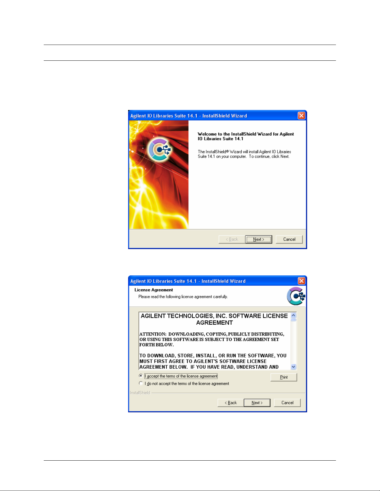
1) Start installation of Agilent VISA. From the VXI Technology, Inc. Distribution CD, run the
program iolibs_suite_14_1_8016_0.exe (or later). At the Welcome screen, click the Next
button.
2) At the License Agreement dialog box, click on the “accept” radio button to accept the license
agreement, and then click Next to continue. If this is not done, installation will cease.
EX2500 Quick Start Guide 21
Page 23
VXI Technology, Inc.
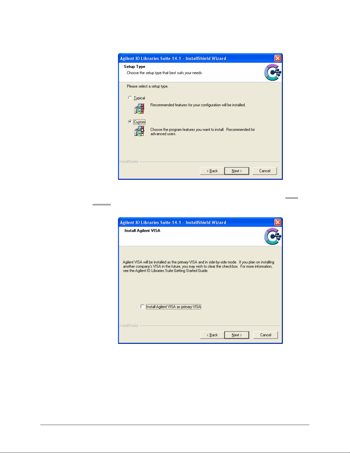
3) At the Setup Type dialog box, select the “Custom” radio button, then click the Next button.
4) At the Install Agilent VISA dialog box, a prompt appears asking if Agilent VISA will be
installed as the primary VISA. Ensure that “Install Agilent VISA as primary VISA” is not
selected
already installed.
, and the click the Next button. The screenshot below is from a system with NI-VISA
22 EX2500 Quick Start Guide
Page 24
www.vxitech.com
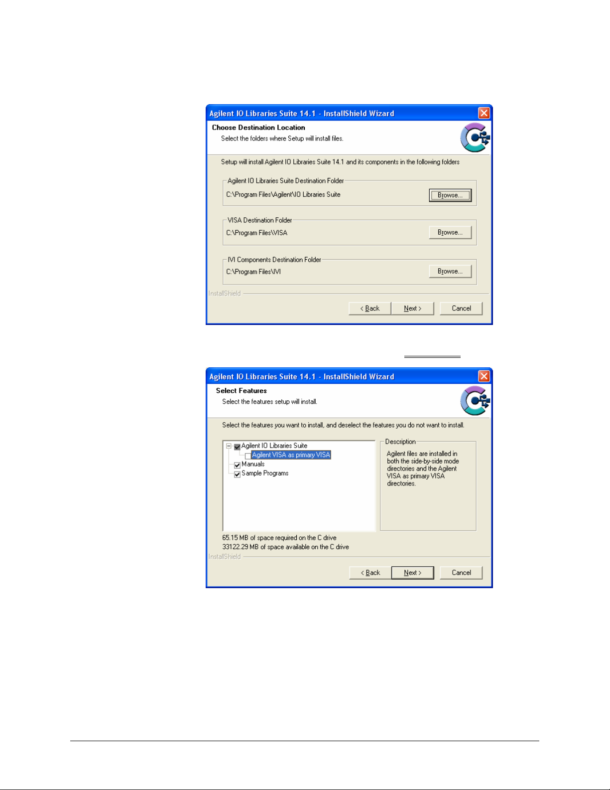
5) No changes are required at the Choose Destination Location dialog box. Click the Next
button to continue.
6) At the Select Features dialog box, a summary of features that will be installed is provided.
Ensure that the “Agilent VISA as primary VISA” check box is not selected
.
EX2500 Quick Start Guide 23
Page 25
VXI Technology, Inc.
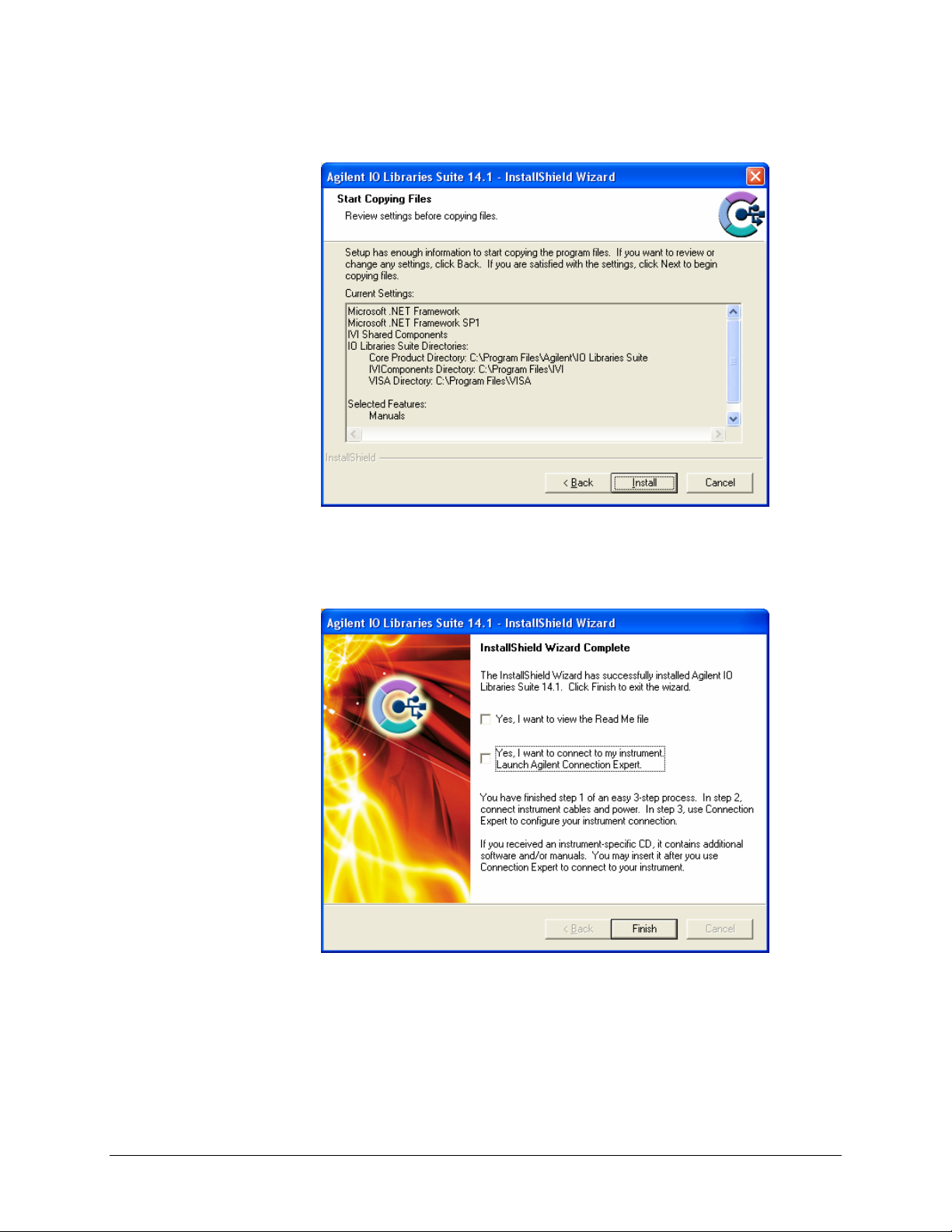
7) Next, the Start Copying Files dialog box will appear. To begin software installation, click the
Install button.
8) Once Agilent VISA installation is complete, the InstallShield Wizard Complete dialog box
will appear. As the EX2500 driver must be installed before the Agilent Connection Expert can
be used, ensure that both check boxes on this dialog box are no selected. Click the Finish
button to complete VISA installation.
24 EX2500 Quick Start Guide
Page 26
www.vxitech.com
EX2500 DRIVER INSTALLATION
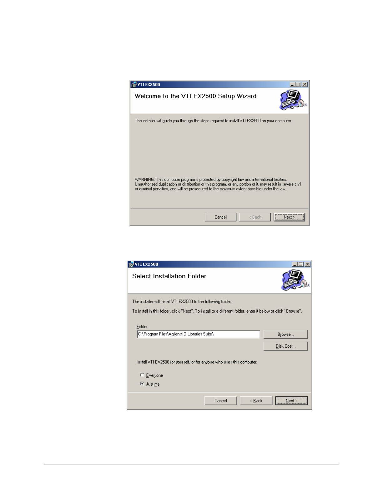
1) From the VXIplug&play Drivers and Product Manuals CD, run the program
EX2500_Driver_R1p0p0.msi (or later). At the Welcome dialog box, click the Next button.
2) From the Select Installation Folder dialog box, select an appropriate radio button according
to host PC demands. No changes are required in the Folder field. Click the Next button to
proceed.
EX2500 Quick Start Guide 25
Page 27
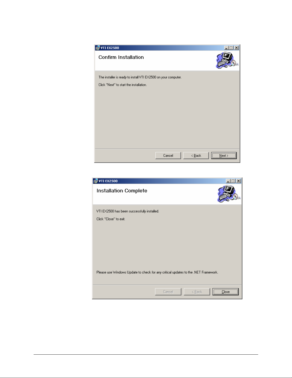
3) At the Confirm Installation dialog box, click the Next button.
VXI Technology, Inc.
4) Click the close button and go to
Configure NI-VISA for Use with Agilent VISA.
26 EX2500 Quick Start Guide
Page 28
www.vxitech.com
CONFIGURE NI-VISA FOR USE WITH AGILENT VISA
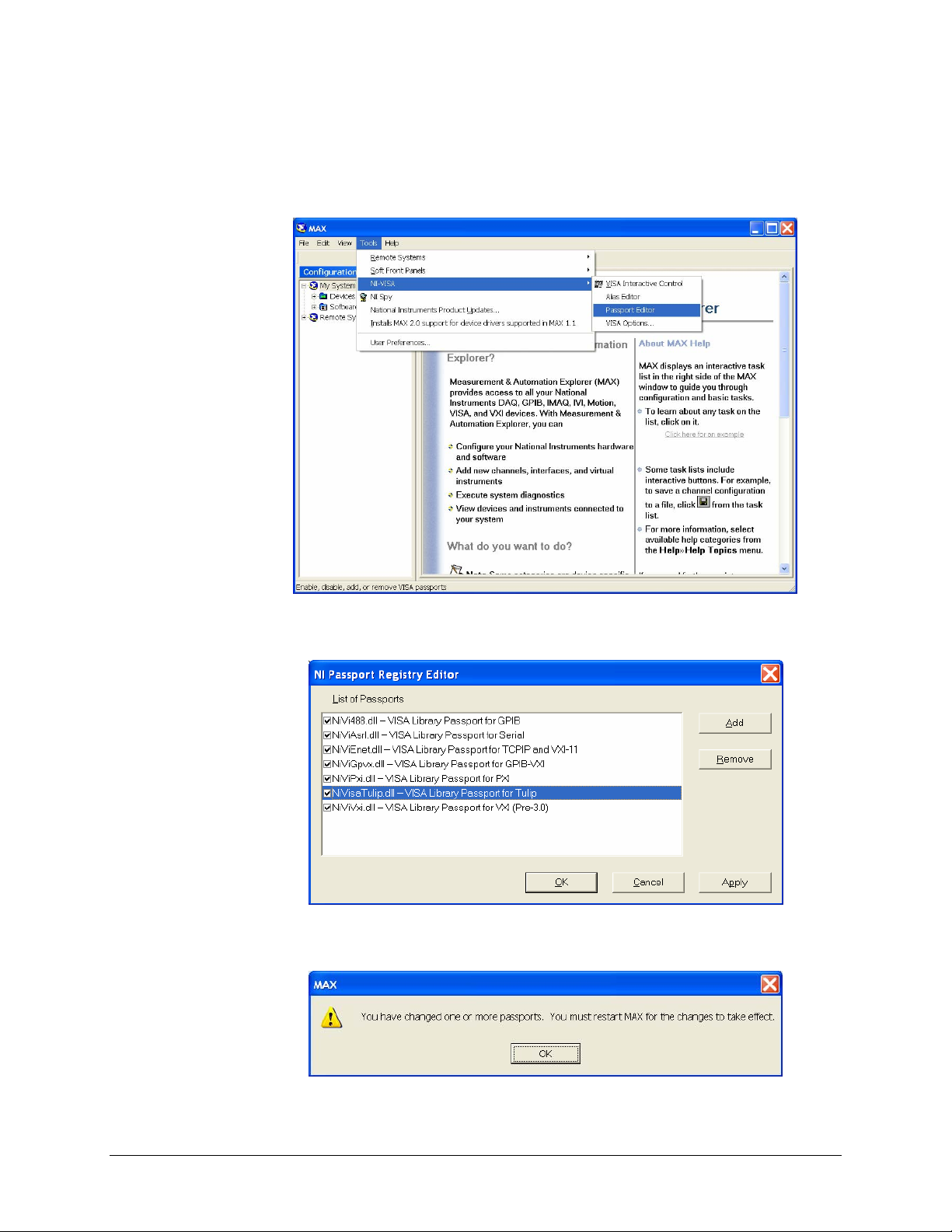
1) Open NI’s MAX® (Measurement and Automation Explorer) software and go to Tools>NI-
VISA>Passport Editor. Note that in other versions of NI_VISA, Passport Editor may be
found in another location. Please refer to the software’s Help file for additional assistance.
2) When the NI Passport Registry Editor dialog box appears, ensure that the NiVisaTulip.dll
check box is selected. Click Apply, and then click OK.
3) A warning will appear, indicating that MAX must be restarted for changes to take effect.
Click OK, then close MAX.
EX2500 Quick Start Guide 27
Page 29
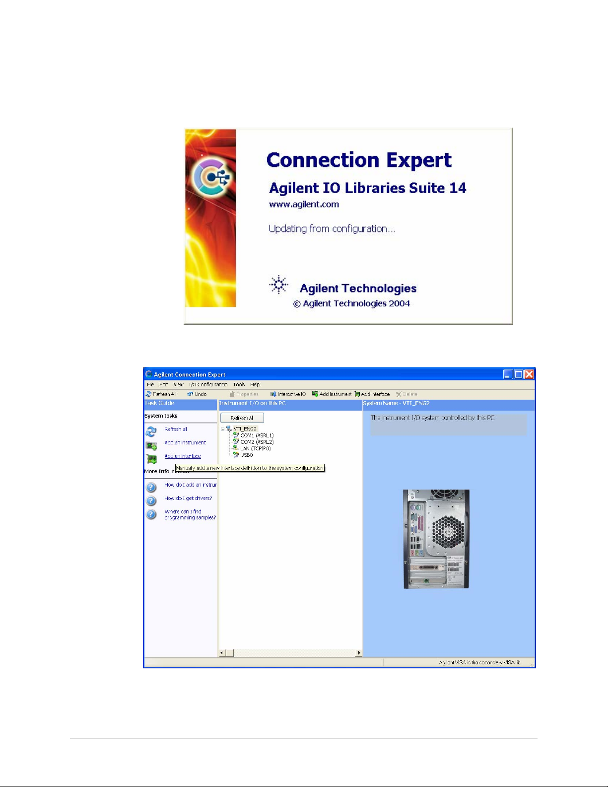
ADD THE EX2500 INTERFACE TO AGILENT VISA
1) Open Agilent’s Connection Expert© from the Start Menu via the path Start > All Programs >
Agilent IO Libraries Suite > Agilent Connection Expert.
VXI Technology, Inc.
2) From the Connection Expert main window, click the “Add an interface” link in the Task
Guide field.
28 EX2500 Quick Start Guide
Page 30
www.vxitech.com
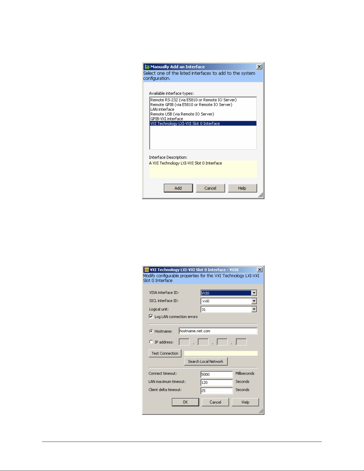
3) From the Manually Add an Interface dialog box, select “VXI Technology LXI-VXI Slot 0
Interface” from the list and then click Add.
4) A configuration window will appear. In VXI systems, the VISA interface ID cannot conflict
with any other existing VXI interface IDs (in multi-mainframe systems). To ensure that this
does not occur, click on Search Local Network on the configuration window. This software
utility will search for EX2500s. If the EX2500 is connected directly to the NIC in the host
controller, the EX2500 software will automatically assign an IP address based on the MAC
address of the module. If the module is connected to a LAN that is DHCP enabled, the DHCP
server will assign an IP address to the module. To determine if a LAN is DHCP enabled,
please contact your Network Administrator.
EX2500 Quick Start Guide 29
Page 31
VXI Technology, Inc.
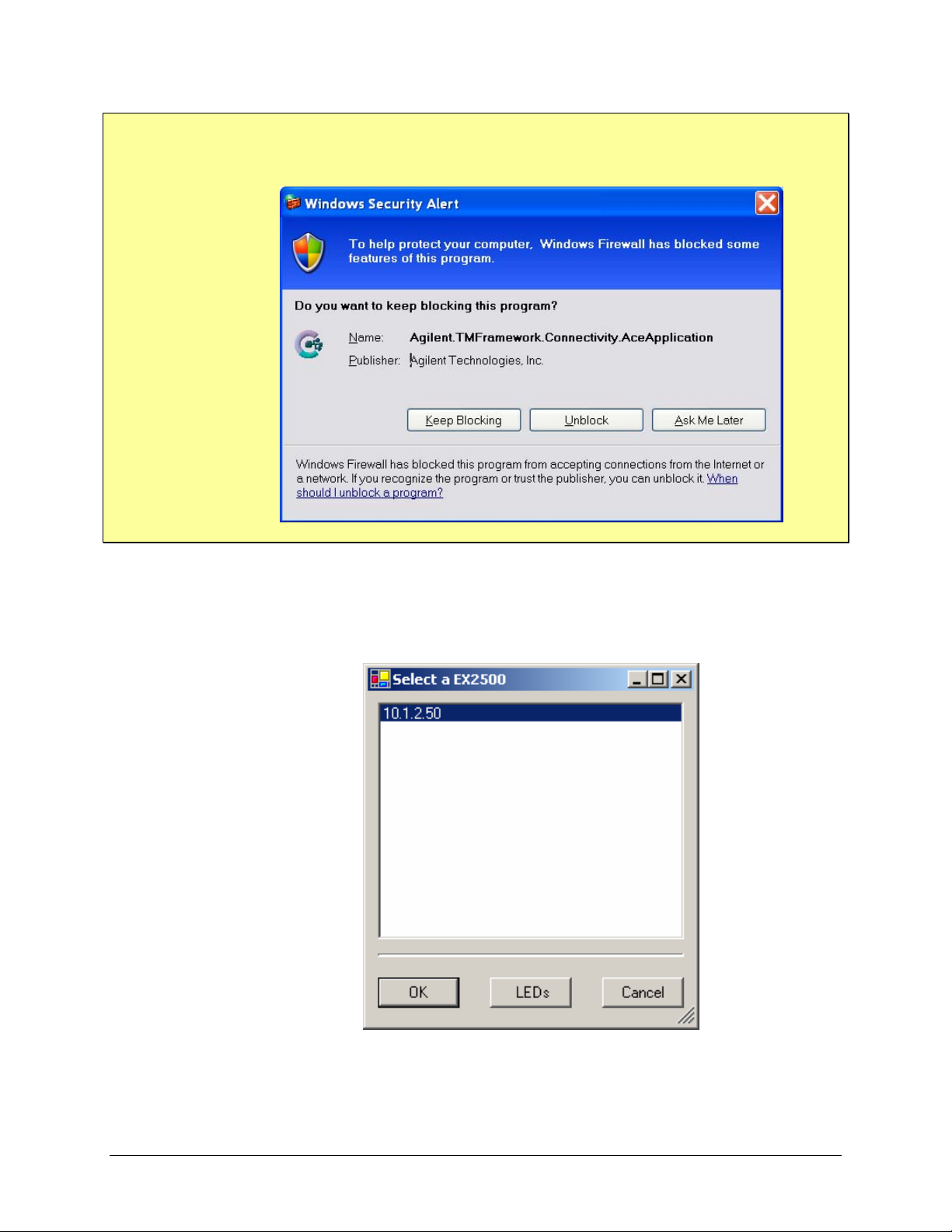
NOTE On PCs running Windows XP, the Windows Firewall utility may try to block Connection
Expert from connecting to the EX2500. To avoid blocking multiple connections, it may be
desirable to turn off Windows Firewall. Refer to Wind o ws Help f or more inf ormation.
5) Connection Expert will display the IP address of all EX2500s discovered on the network.
Clicking LEDs runs a test on the LEDs of the highlighted EX2500 causing the MODE LEDs
to blink in a “leap-frog pattern.” An additional dialog box will appear asking if this is the
correct module. It this is the module of interest, click OK to establish the highlighted EX2500
as the target module
30 EX2500 Quick Start Guide
Page 32
www.vxitech.com
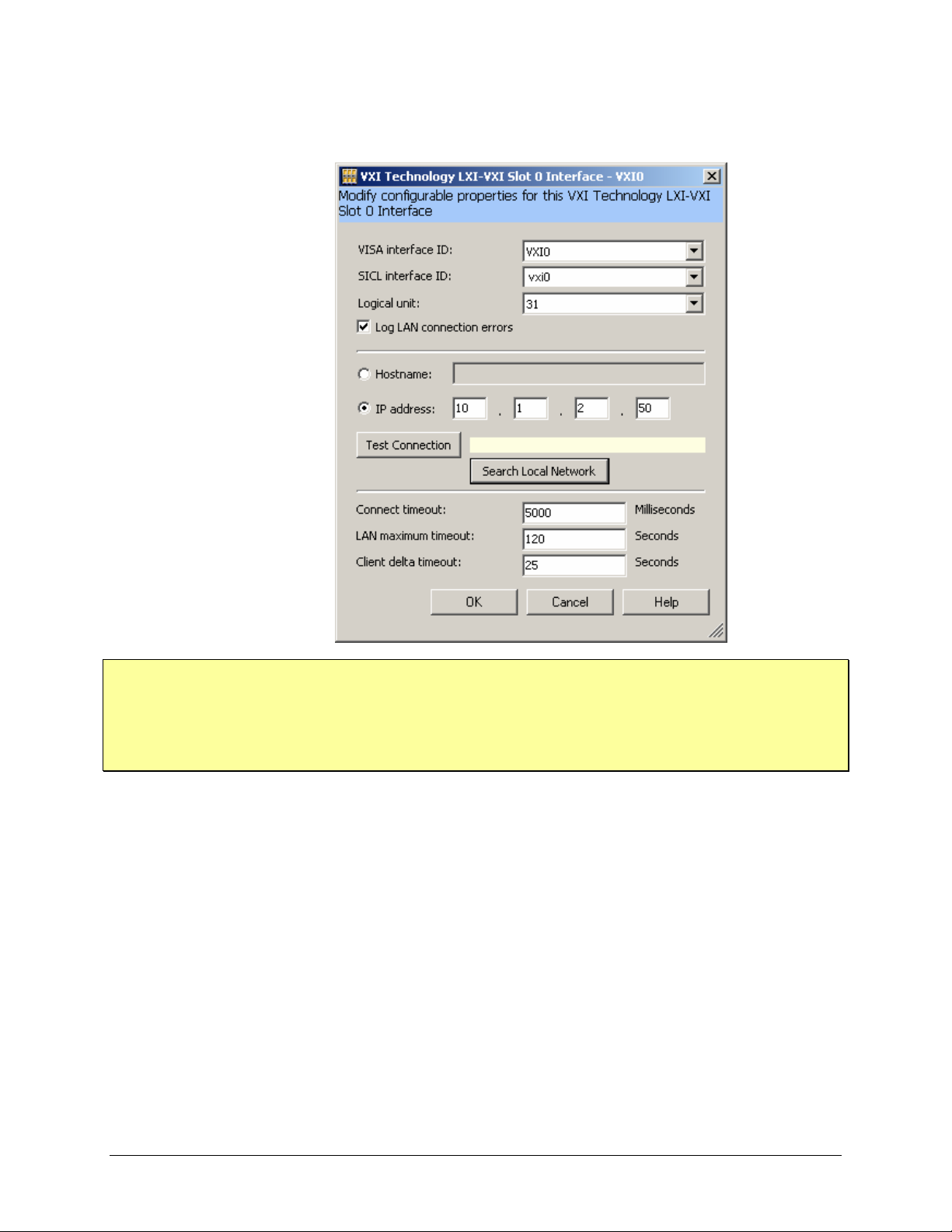
The IP address field will now contain the IP of the target EX2500. Clicking OK assigns the
VISA interface ID shown to the target EX2500.
NOTE This process should be repeated for each EX2500 included in a test syste m. It is imperative that
each EX2500 module have a unique VISA interface ID.
If a MXI-2 interface will be installed into a mainframe after an EX2500 has been installed, the
EX2500 should have its VISA interface ID reassigned if its ID is VXI0. If this is not done, it will
cause the I/O software to perform improperly and make accessing the EX2500 impossible.
EX2500 Quick Start Guide 31
Page 33
VXI Technology, Inc.
6) The Slot 0 interface to the EX2500 should now appear in the Instrument I/O on this PC
field. The adjacent field contains buttons that allow for EX2500 properties to be changed and
provide access to the EX2500’s web interface.
The EX2500 soft front panel and other programs should now be accessible.
32 EX2500 Quick Start Guide
Page 34
www.vxitech.com
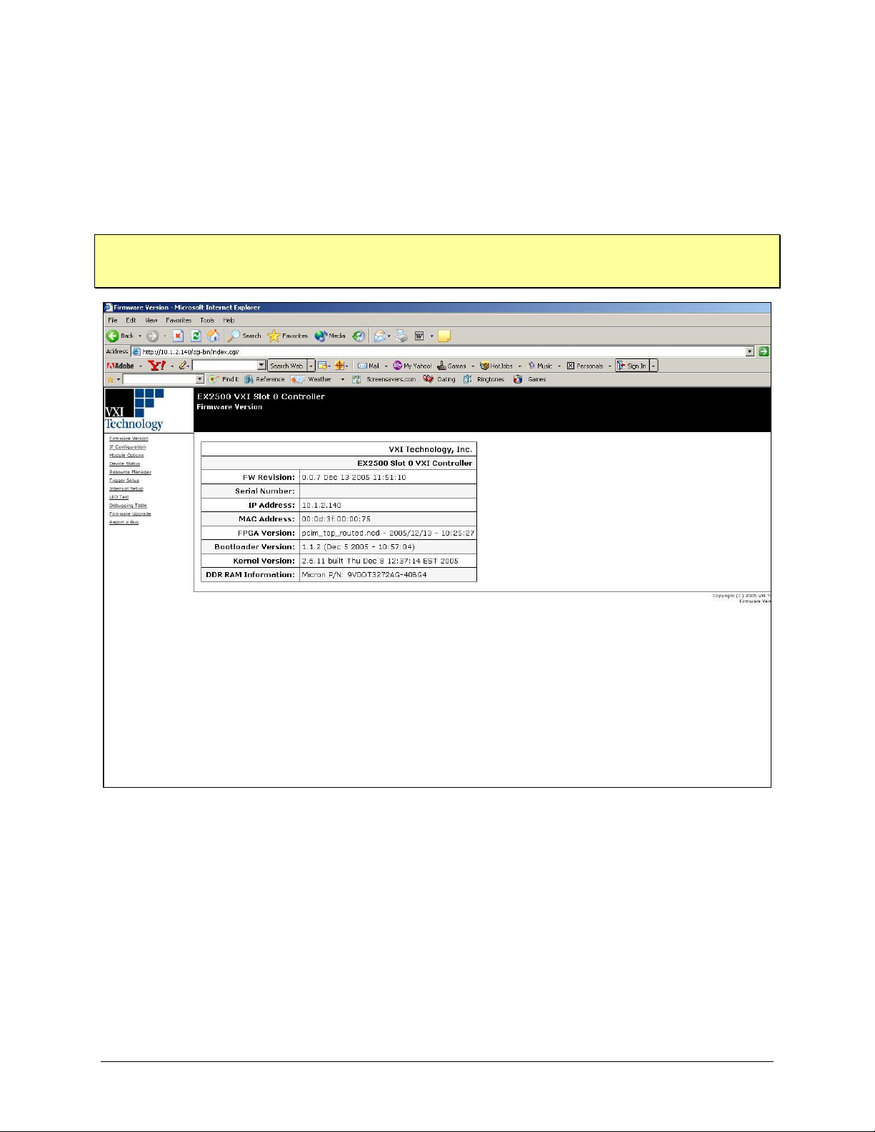
WEB INTERFACE
The EX2500’s embedded web interface can be accessed via standard Internet browsers, such as
Internet Explorer
©
. Simply type the module’s IP address (10.1.2.140 from the example above) into
the browser’s address bar to access the web interface. The web interface allows user’s to pass
formatted I/O commands (to message-based devices) or to directly access device registers through
the “device status” hyperlink.
NOTE The web interface currently supports network configuration of the EX2500 along with trigger
setup, interrupt setup, and other functions. Because the EX2500 includes RESMAN in the module,
the modules in the rack can be identified, peeked and poked, or sent word serial commands.
F
IGURE 1-1: EX2500 WEB INTERFACE
EX2500 Quick Start Guide 33
Page 35
V
XI ACC
SYSFAIL
CLK
IN
CLK
OUT
RESET
VXI Technology, Inc.
FRONT PANEL INDICATORS
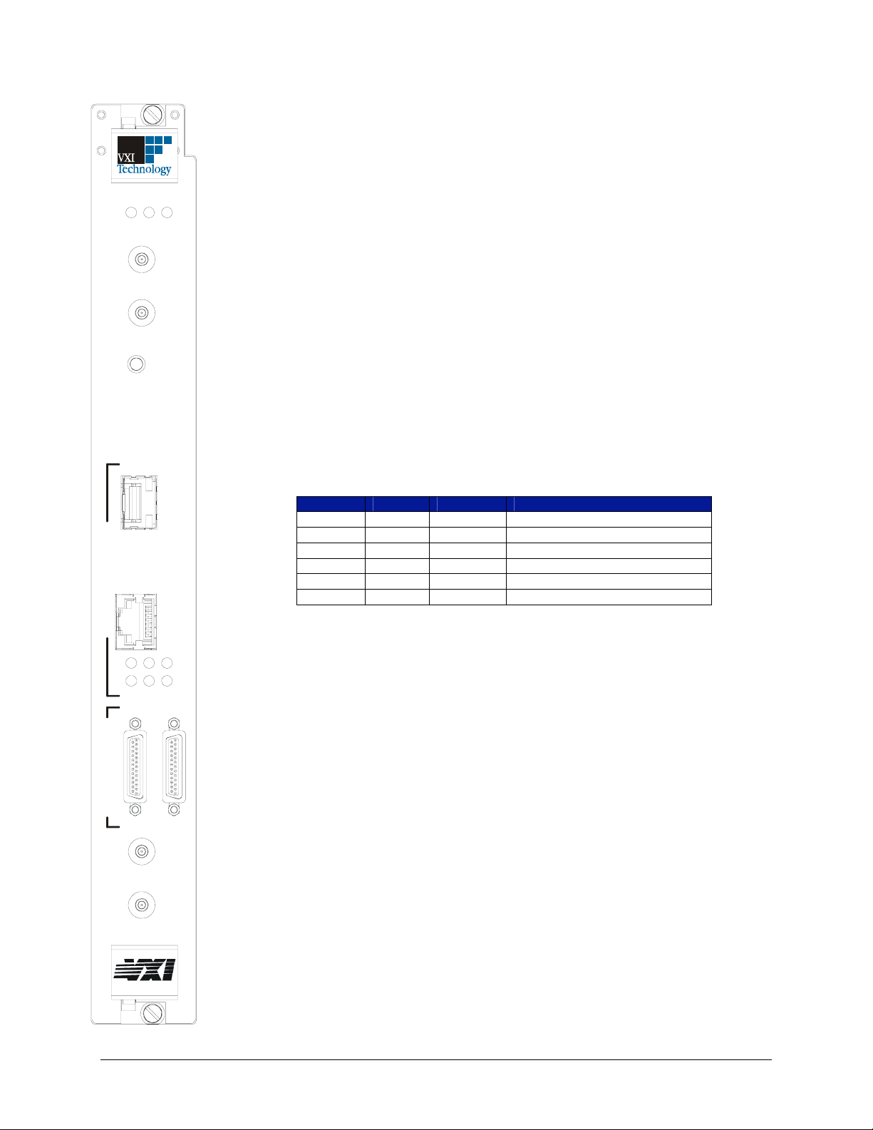
The front panel of the unit includes the following interfaces and indicators:
• VXI_ACC – VXI access indication, this LED will blink green for backplane accesses
that terminate properly. It will blink orange for accesses that terminate in retry or bus
error.
• SYSFAIL – This LED shows the Sysfail status of the EX2500.
• EXT CLK IN and OUT – These SMB connectors provide external clocking options for
the EX2500.
• RESET – Issues system reset and initiates Resource Manager Execution.
• GIGABIT ETHERNET – The module provides connection to gigabit Ethernet via
either a Small Form Factor Pluggable (SFP) fiber module or via standard category 5
(Cat 5) twisted pair. The EX2500 automatically detects which interface is active and
switches without user intervention. For Cat 5 connections, the EX2500 provides au toMDIX (medium dependent interface crossover) functionality that automatically handles
crossover in point-to-point connections. The unit will also detect and correct pairs that are
wired backwards. Therefore, crossover cables can be used, although are not required.
Multiple gigabit indicators are present to provide detailed information to the user
regarding link status. Individual TX, RX, and DUPLEX LEDs are provided. Link status
is shown on mode LEDs A, B, and C per the following table. NOTE: Ensure that LED
control is returned to “Normal” when exiting the LED test section of the web interface.
SFP
FIBER
OPTIC
CAT5e
GIGABIT ETHERNET LXI TRIGGER BUS
A
Tx Rx DUPLEX
B C
TRIG
TRIG
M
O
D
E
IN
OUT
LED A LED B LED C Mode
OFF ON ON 1000 Mb/s Fiber, Link-up
ON OFF ON 1000 Mb/s Cat 5 Master, Link-up
OFF OFF ON 1000 Mb/s Cat 5 Slave, Link-up
OFF ON OFF 100 Mb/s Cat 5, Link-up
ON OFF OFF 10 Mb/s Cat 5, Link-up
OFF OFF OFF Link Down
• TRIGGER BUS – The trigger bus is an 8-channel LXI compliant trigger mechanism that
can be used to route all VXI TTL triggers rack to rack or rack to LXI module.
• EXT TRIG IN and OUT – These SMB connectors allow users to route VXI TTL
triggers and trigger bus signals.
EX2500
bus
34 EX2500 Quick Start Guide
Page 36

Artisan Technology Group is your source for quality
new and certied-used/pre-owned equipment
• FAST SHIPPING AND
DELIVERY
• TENS OF THOUSANDS OF
IN-STOCK ITEMS
• EQUIPMENT DEMOS
• HUNDREDS OF
MANUFACTURERS
SUPPORTED
• LEASING/MONTHLY
RENTALS
• ITAR CERTIFIED
SECURE ASSET SOLUTIONS
SERVICE CENTER REPAIRS
Experienced engineers and technicians on staff
at our full-service, in-house repair center
Instra
Remotely inspect equipment before purchasing with
our interactive website at www.instraview.com
Contact us: (888) 88-SOURCE | [email protected] | www.artisantg.com
SM
REMOTE INSPECTION
View
WE BUY USED EQUIPMENT
Sell your excess, underutilized, and idle used equipment
We also offer credit for buy-backs and trade-ins
www.artisantg.com/WeBuyEquipment
LOOKING FOR MORE INFORMATION?
Visit us on the web at www.artisantg.com for more
information on price quotations, drivers, technical
specications, manuals, and documentation
 Loading...