

Page 1

bus
CT-100C SERIES
SIX-SLOT VXIBUS CHASSIS
USER’S
MANUAL
P/N: 82-0102-000
Released June 7th, 2016
VXI Technology, Inc.
2031 Main Street
Irvine, CA 92614-6509
(949) 955-1894
Page 2

VXI Technology, Inc.
2
Page 3

www.vxitech.com
CT-100C Preface 3
TABLE OF CONTENTS
INTRODUCTION
Table of Contents ...................................................................................................................................................... 3
Certification ......................................................................................................................................................... 4
Warranty............................................................................................................................................................... 4
Limitation of Warranty ......................................................................................................................................... 4
Restricted Rights Legend ..................................................................................................................................... 4
Declaration of Conformity ........................................................................................................................................ 5
General Safety Instructions ....................................................................................................................................... 6
Terms and Symbols .............................................................................................................................................. 6
Warnings .............................................................................................................................................................. 6
Support Resources .................................................................................................................................................... 8
SECTION 1 .................................................................................................................................................................... 9
Introduction ............................................................................................................................................................... 9
Introduction .......................................................................................................................................................... 9
General Description ........................................................................................................................................... 10
Backplane ........................................................................................................................................................... 10
Performance ....................................................................................................................................................... 10
Flexibility ........................................................................................................................................................... 11
CT-100C Mainframe Features ............................................................................................................................ 12
Voltage Monitor LEDs ....................................................................................................................................... 13
CT-100C Specifications ..................................................................................................................................... 15
SECTION 2 .................................................................................................................................................................. 19
Installation .............................................................................................................................................................. 19
Introduction ........................................................................................................................................................ 19
Backplane ........................................................................................................................................................... 19
Remote Power-On Option .................................................................................................................................. 20
+5 V Standby Usage ........................................................................................................................................... 21
Fan Speed Switch ............................................................................................................................................... 22
Rackmount Option Installation ............................................................................................................................... 23
Overview ................................ ............................................................................................................................ 23
Rackmount Kit Installation ..................................................................................................................................... 24
Rack Slide Installation (20” and 24”) ..................................................................................................................... 26
Rackmount Door Kit Installation ............................................................................................................................ 28
Acrylic Rackmount Door Kit Installation ............................................................................................................... 30
Installation of VXI Modules ................................................................................................................................... 32
Overview ................................ ............................................................................................................................ 32
Disconnecting the Mainframe ................................................................................................................................. 33
SECTION 3 .................................................................................................................................................................. 35
Service Information................................................................................................................................................. 35
Introduction ........................................................................................................................................................ 35
Replicable Parts List .......................................................................................................................................... 35
CT-100C Power Supply Replacement ................................................................................................................ 36
Cleaning the Mainframe ..................................................................................................................................... 38
INDEX ......................................................................................................................................................................... 39
Page 4

VXI Technology, Inc.
4 CT-100C Preface
CERTIFICATION
VXI Technology, Inc. (VTI) certifies that this product met its published specifications at the time of shipment from
the factory. VTI further certifies that its calibration measurements are traceable to the United States National
Institute of Standards and Technology (formerly National Bureau of Standards), to the extent allowed by that
organization’s calibration facility, and to the calibration facilities of other International Standards Organization
members.
WARRANTY
The product referred to herein is warranted against defects in material and workmanship for a period of three years
from the receipt date of the product at customer’s facility. The same warranty applies to the power supply for a
period of one year. The sole and exclusive remedy for breach of any warranty concerning these goods shall be repair
or replacement of defective parts, or a refund of the purchase price, to be determined at the option of VTI.
For warranty service or repair, this product must be returned to a VXI Technology authorized service center. The
product shall be shipped prepaid to VTI and VTI shall prepay all returns of the product to the buyer. However, the
buyer shall pay all shipping charges, duties, and taxes for products returned to VTI from another country.
VTI warrants that its software and firmware designated by VTI for use with a product will execute its programming
when properly installed on that product. VTI does not however warrant that the operation of the product, or software,
or firmware will be uninterrupted or error free.
LIMITATION OF WARRANTY
The warranty shall not apply to defects resulting from improper or inadequate maintenance by the buyer, buyersupplied products or interfacing, unauthorized modification or misuse, operation outside the environmental
specifications for the product, or improper site preparation or maintenance.
VXI Technology, Inc. shall not be liable for injury to property other than the goods themselves. Other than the
limited warranty stated above, VXI Technology, Inc. makes no other warranties, express or implied, with respect to
the quality of product beyond the description of the goods on the face of the contract. VTI specifically disclaims the
implied warranties of merchantability and fitness for a particular purpose.
RESTRICTED RIGHTS LEGEND
Use, duplication, or disclosure by the Government is subject to restrictions as set forth in subdivision (b)(3)(ii) of the
Rights in Technical Data and Computer Software clause in DFARS 252.227-7013.
VXI Technology, Inc.
2031 Main Street
Irvine, CA 92614-6509 U.S.A.
Page 5

www.vxitech.com
CT-100C Preface 5
DE C L A R A T I O N O F C O N F O R M I T Y
Declaration of Conformity According to EN ISO/IEC 17050-1:2004
MANUFACTURER’S NAME VXI Technology, Inc.
MANUFACTURER’S ADDRESS 2031 Main Street
Irvine, California 92614-6509
PRODUCT NAME Six-Slot VXIbus Chassis
MODEL NUMBER(S) CT-100C
PRODUCT OPTIONS All
PRODUCT CONFIGURATIONS All
VTI Instruments (formerly VXI Technology) declares that the aforementioned product conforms to
the requirements of the Low Voltage directive (European Council directive 2014/35/EU, dated 22
July 1993) and the Electromagnetic Compatibility directive (European Council directive
2014/30/EU; generally referred to as the EMC directive). In substantiation, the products were
tested and/or evaluated to the standards shown below:
SAFETY EN61010-1:2010
EMC EN61326-1:2013
EN55011 Class A Group 1
EN61000-4-2
EN61000-4-3
EN61000-4-4
EN61000-4-5
EN61000-4-6
EN61000-4-8
EN61000-4-11
CISPR 22
June 2016
Steve Mauga, QA Manager
Page 6
VXI Technology, Inc.
6 CT-100C Preface
GENERAL SAFETY INSTRUCTIONS
Review the following safety precautions to avoid bodily injury and/or damage to the product.
These precautions must be observed during all phases of operation or service of this product.
Failure to comply with these precautions, or with specific warnings elsewhere in this manual,
violates safety standards of design, manufacture, and intended use of the product.
Service should only be performed by qualified personnel.
TERMS AND SYMBOLS
These terms may appear in this manual:
WARNING
Indicates that a procedure or condition may cause bodily injury or death.
CAUTION
Indicates that a procedure or condition could possibly cause damage to
equipment or loss of data.
These symbols may appear on the product:
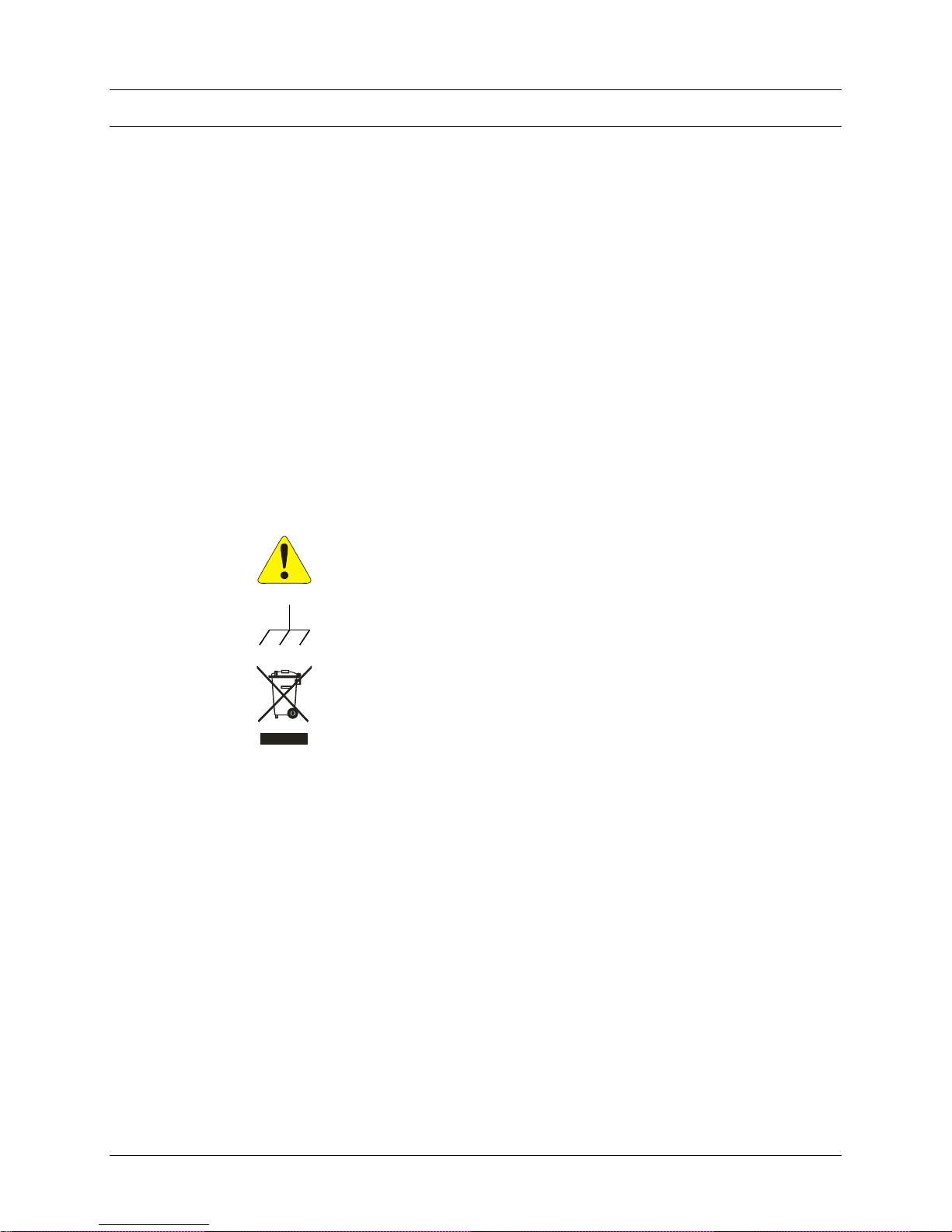
ATTENTION - Important safety instructions
Frame or chassis ground
Indicates that the product was manufactured after August 13, 2005. This mark is
placed in accordance with EN 50419, Marking of electrical and electronic
equipment in accordance with Article 11(2) of Directive 2002/96/EC (WEEE).
End-of-life product can be returned to VTI by obtaining an RMA number. Fees
for take-back and recycling will apply if not prohibited by national law.
WARNINGS
Follow these precautions to avoid injury or damage to the product:
Use Proper Power Cord
To avoid hazard, only use the power cord specified for this product.
Use Proper Power Source
To avoid electrical overload, electric shock, or fire hazard, do not
use a power source that applies other than the specified voltage.
Page 7

www.vxitech.com
CT-100C Preface 7
WARNINGS (CONT.)
Avoid Electric Shock
To avoid electric shock or fire hazard, do not operate this product
with the covers removed. Do not connect or disconnect any cable,
probes, test leads, etc. while they are connected to a voltage source.
Remove all power and unplug unit before performing any service.
Service should only be performed by qualified personnel.
Ground the Product
This product is grounded through the grounding conductor of the
power cord. To avoid electric shock, the grounding conductor must
be connected to earth ground.
Operating Conditions
To avoid injury, electric shock or fire hazard:
-
Do not operate in wet or damp conditions.
-
Do not operate in an explosive atmosphere.
-
Operate or store only in specified temperature range.
-
Provide proper clearance for product ventilation to prevent
overheating.
-
DO NOT operate if any damage to this product is suspected.
Product should be inspected or serviced only by qualified
personnel.
Improper Use
The operator of this instrument is advised that if equipment is
used in a manner not specified in this manual, the protection
provided by this equipment be may be impaired.
Page 8

VXI Technology, Inc.
8 CT-100C Preface
SUPPORT RESOURCES
Support resources for this product are available on the Internet and at VTI Instruments customer
support centers.
VTI Instruments Corp.
World Headquarters
VTI Instruments Corp.
2031 Main Street
Irvine, CA 92614-6509
Phone: (949) 955-1894
Fax: (949) 955-3041
VTI Instruments
Cleveland Instrument Division
5425 Warner Road
Suite 13
Valley View, OH 44125
Phone: (216) 447-8950
Fax: (216) 447-8951
AMETEK Instruments Pvt. Ltd. India
4th Floor, Block A,
Divyashree NR Enclave,
EPIP Industrial Area,
Whitefield,
Bangalore – 560066 INDIA
Phone: +91 80 6782 3200
Fax: +91 80 6782 3232
Technical Support
Phone: (949) 955-1894
Fax: (949) 955-3041
E-mail: [email protected]
Visit http://www.vtiinstruments.com for worldwide support sites and service plan information.
Page 9
www.vxitech.com
CT-100C Introduction 9
SECTION 1
INTRODUCTION
INTRODUCTION
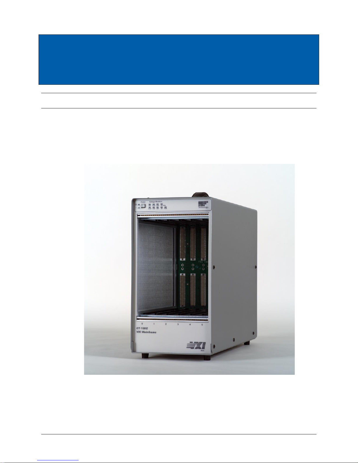
The CT-100C portable C-size VXIbus mainframe provides cost-effective test situations in a small
footprint. When using VMIP instruments such as DMMs, waveform generators, digitizers, etc.,
complete test scenarios can easily be configured.
FIGURE 1-1: CT-100C SIX SLOT CHASSIS
Page 10

VXI Technology, Inc.
10 CT-100C Introduction
GENERAL DESCRIPTION
The CT-100C chassis is a portable, C-size, six-slot, VXIbus compatible chassis that conforms fully
to VXIbus Specification Revision 2.0. The chassis employs a multi-layer backplane to ensure
premium VXIbus and VMEbus performance and provides all power supplies required by the
VXIbus specification.
The CT-100C supports conventional existing rack designs through an optional rackmounting kit
(see Section 1). The six-slot design minimizes the use of precious rack space and is an economical
alternative to a larger chassis when fewer slots are required.
The CT-100C chassis contains six slots in the card cage, five of which are available for use by
VXIbus compatible instruments. The sixth slot in the card cage (slot 0) is typically dedicated to the
VXIbus Resource Manager.
The CT-100C is designed to operate at line frequencies between 47 Hz and 63 Hz and utilizes a
power supply that automatically adjusts to accept line voltages between 100 V ac and 240 V ac.
There is an internal fuse that provides protection against catastrophic failures and is designed to
operate within the valid input range.
The rear panel provides a connector for 5V STANDBY. Power supplied to this connector is
passed directly to the backplane line +5V STDBY. This allows properly configured systems to
take advantage of an alternate power supply source, i.e., battery backup of memory or energizing
high stability reference oscillators.
BACKPLANE
The backplane is a monolithic, multi-layer design, with automatic, solid-state daisy-chain
jumpering for the interrupt acknowledge and VMEbus grant lines. This eliminates the need for
manual jumpering and provides improved reliability over mechanical jumper-less backplane
designs. Instrument modules can now be added or removed without concern for the backplane
configuration.
PERFORMANCE
The CT-100C uses a pressurized airflow system. As air enters the mainframe from the rear, it is
pressurized below the cards and is then evenly distributed across all slots and along the total length
of each card slot, avoiding hot spots common in other designs. The air exhausts through the top
and away from the user. This cooling approach helps increase MTBF (Mean Time Before Failure)
figures and module performance.
High-quality power supplies are used in the CT-100C that are UL, CSA, and TUV approved. The
power supplies are short-circuit, over-voltage, reverse-voltage and thermal-shutdown protected.
Auto-ranging power supplies are used to avoid any concern about the voltage source used. In
addition, all supply lines are monitored and displayed on the front panel to provide user feedback
of correct operation (see Figure 1-4).
Page 11
www.vxitech.com
CT-100C Introduction 11
FLEXIBILITY
The CT-100C is designed to provide flexibility of use in bench-top and rackmount applications, as
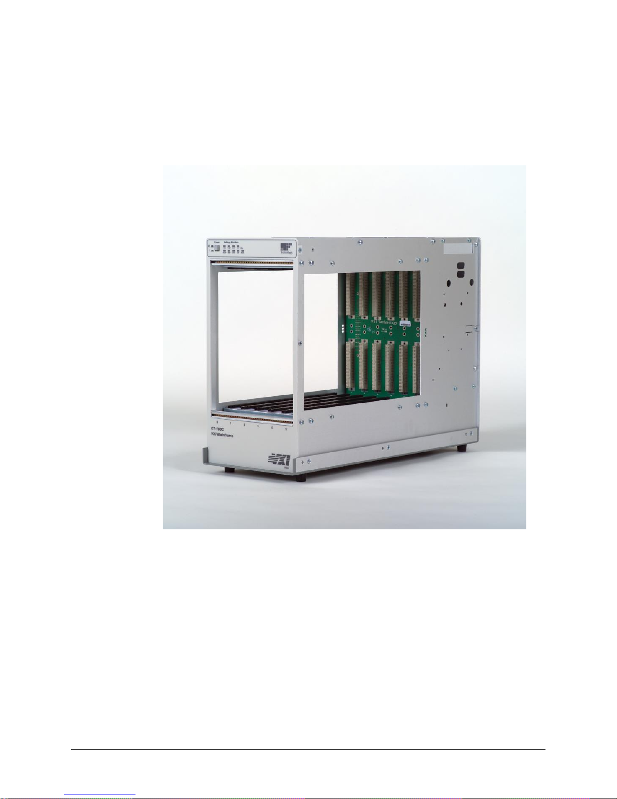
well as in portable environments. The outside cover is removable for easy access to the VXIbus
modules during bench-top development, troubleshooting, or calibration. For rackmount
applications, a rackmount kit allows the CT-100C to mount flush or be recessed four inches. A
latched door is provided with the rackmount kit, which can be user-modified to accept connectors,
switches, or indicators. See Section 1 for rackmount installation.
FIGURE 1-2: CT-100C SIX-SLOT CHASSIS – COVERS OFF
Page 12
VXI Technology, Inc.
12 CT-100C Introduction
CT-100C MAINFRAME FEATURES
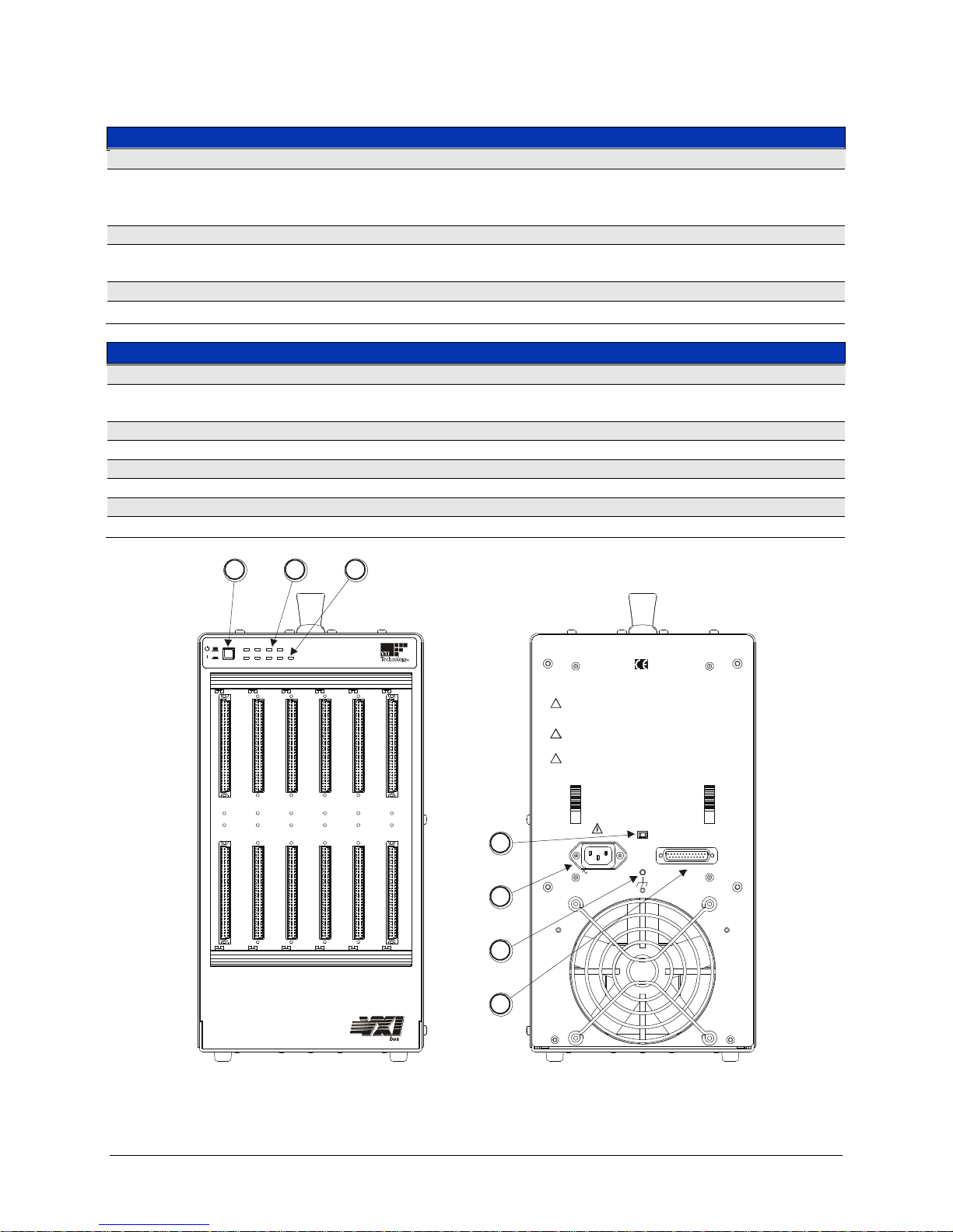
FRONT PANEL FEATURES
POWER SWITCH
Feature 1
When elevated, the mainframe is in standby mode, where power is supplied to the
mainframe, but not to the VXI modules.
When depressed, power is supplied to both mainframe and VXI modules
VOLTAGE INDICATORS
Feature 2
Indicates whether specific backplane voltages are within specifications. See Figure 1-4
for details.
FAN INDICATOR
Feature 3
Indicates whether the fan voltages are within specifications. See Figure 1-4 for details.
REAR PANEL FEATURES
FAN SPEED SWITCH
Feature 4
Enables the user to vary the speed of the fan between HIGH and LOW. See Figure 1-3
for details.
J200 CONNECTOR
Feature 5
AC power receptacle.
GROUND STUD
Feature 6
Used to electrical ground the mainframe.
J201 CONNECTOR
Feature 7
See Figure 1-5 and Table 1-1 for connector pin assignments.
VXI Technology
FAN SPEED
HIGH / LOW
J201
MONITOR / CONTROL
100-240 VAC
10A MAX.
47 - 63 Hz
J200
WARNING - TO PREVENT POSSIBLE ELECTRIC SHOCK HAZARD, DISCONNECT POWER
CORD BEFORE REMOVING THE POWER SUPPLY MODULE FROM THE MAINFRAME.
ATTENTION - POUR EMP Ê CHER LE RISQUE POSSIBLE DE D É CHARGE É LECTRIQUE,
DEBRANCHER LE CORDON DE SECTEUR AVANT D'ENLEVER LE MODULE
D'ALIMENTATION D' É NERGIE DE L'UNIT É CENTRALE .
WARNING - FOR PROTECTION FROM ELECTRIC SHOCK, THE GROUNDING CONNECTION
IN THE POWER CORD MUST BE PROPERLY CONNECTED.
ATTENTION - POUR LA PROTECTION CONTRE LE CHOC É LECTRIQUE , LA PRIS E DE
TERRE AU SOL DANS LE CORDON DE SECTEUR DOIT Ê TRE CORRECTMENT RELI É E.
WARNING - NO OPERATOR SERVICEABLE PARTS INSIDE. REFER SERVICING TO
TRAINED SERVICE PERSONNEL.
ATTENTION - AUCUNES PI È CES REPARABLES PAR UN OP É RATEUR À L'INT É RIE UR.
R É F É REZ L'ENTRETIEN AU PERSONNEL QUALIFI É.
!
!
!
0 1 2 3 4 5
Voltage Monitors Power
+5V +12V +24V +5V Stby
-5.2V -12V -24V -2V FAN
CT-100C
VXI Mainframe
1 2
3
4
5
6
7
FIGURE 1-3: MAINFRAME FEATURE LOCATIONS
Page 13
www.vxitech.com
CT-100C Introduction 13
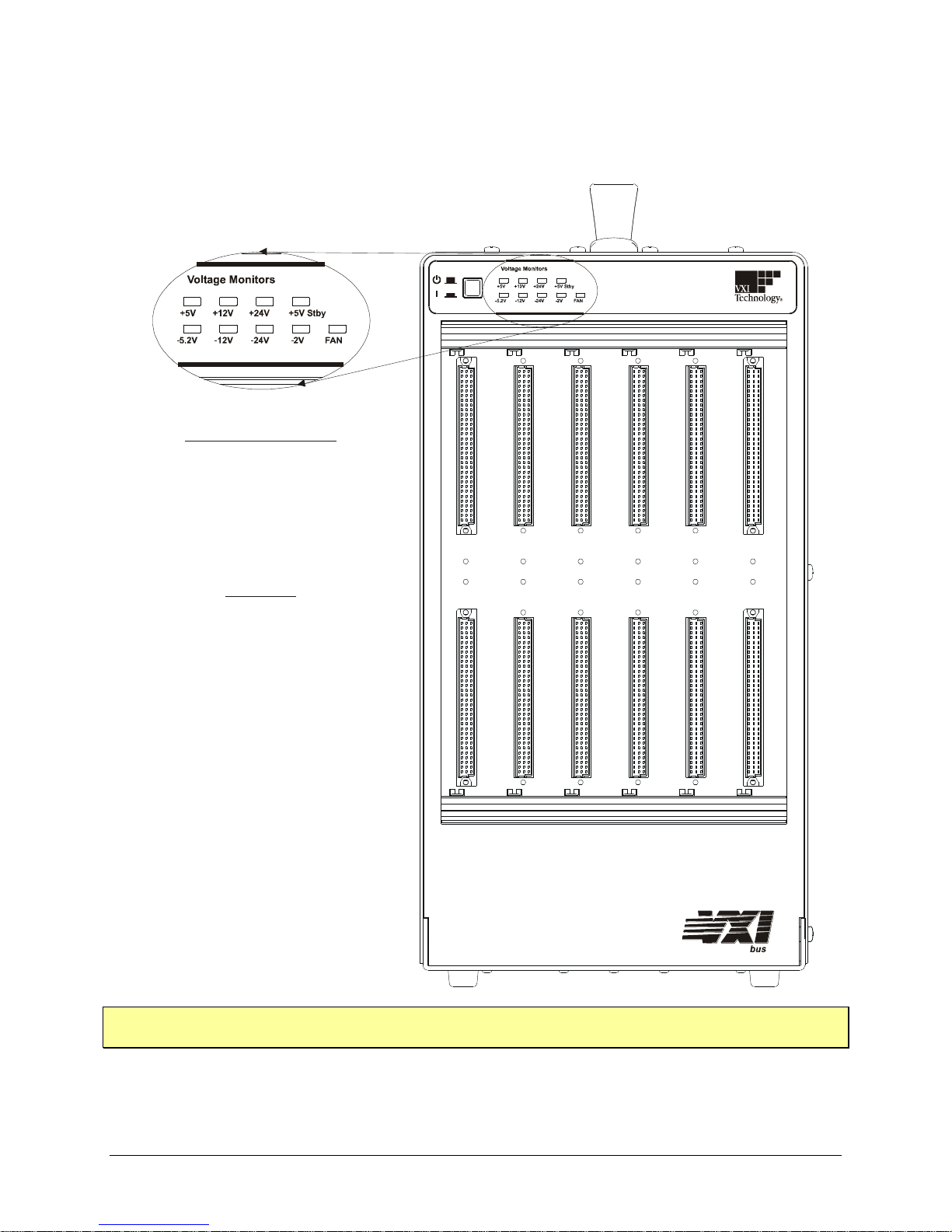
VOLTAGE MONITOR LEDS
The power supply lines are monitored and displayed on the front panel, providing information
pertaining to the chassis operational status.
0 1 2 3 4 5
Voltage Monitors Power
+5V +12V +24V +5V Stby
-5.2V -12V -24V -2V FAN
CT-100C
VXI Mainframe
Voltage Monitor LEDs
Green : Within Voltage Specifications
: Under Voltage Specifications
: Over Voltage Specifications
Not Lit
Red
FAN LEDs
*Note: +5 V Stby is lit only when the +5 V is supplied by the
user to the + 5 V Stby pins (pins 8 & 12) of the monitor
connector located on the rear panel.
Green : Within Voltage Specifications
: Under Voltage Specifications
: Over Voltage Specifications
Not Lit
Red
NOTE At power up, the voltage monitor LED may blink for the first several seconds if the fan speed is set
to “HIGH”.
FIGURE 1-4: FRONT PANEL VOLTAGE MONITORS
Page 14
VXI Technology, Inc.
14 CT-100C Introduction
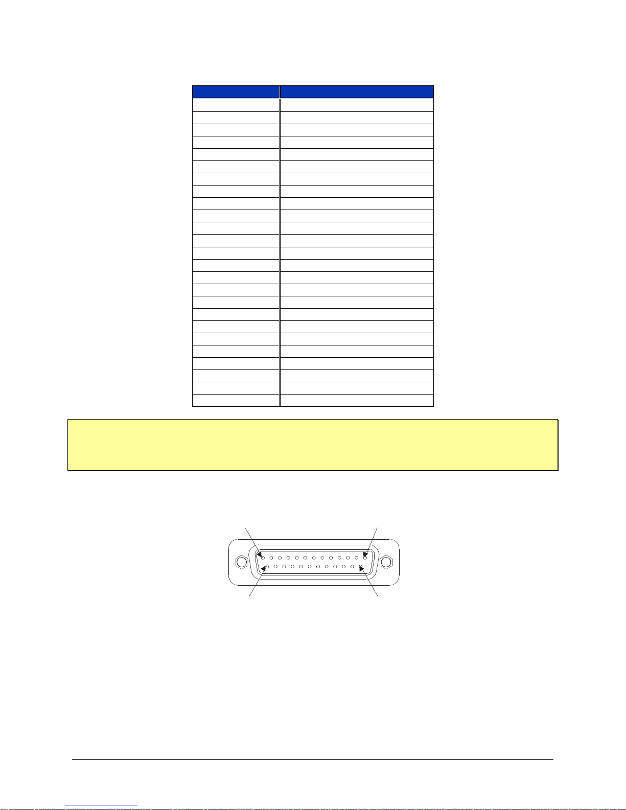
TABLE 1-1: J201 CONNECTOR PIN ASSIGNMENTS
Pin Number
Description
1
+5 V Monitor†
2
-12 V Monitor†
3
-24 V Monitor†
4
-2 V Monitor†
5
Remote Power Switch
6
+5 V Output‡
7
+12 V Output‡
8
+5 V Standby Input
9
Ground
10
Backplane Reset I/O
11
N/C
12
N/C
13
Fan OK Output
14
+12 V Monitor†
15
+24 V Monitor†
16
-5.2 V Monitor†
17
Ground
18
Remote Power Switch Return
19
Ground
20
Ground
21
+5 V Standby
22
Ground
23
AC Fail I/O
24
Ground
25
N/C
NOTE Monitor lines function as outputs only.
‡
Pin 6 and Pin 7 (+5 V Output and +12 V Output, respectively) can provide 0.5 A from the power
supply.
Both jackscrews connect to ground.
Pin 13
Pin 1
Pin 25
Pin 14
FIGURE 1-5: J201 CONNECTOR PIN DETAIL
Page 15

www.vxitech.com
CT-100C Introduction 15
CT-100C SPECIFICATIONS
GENERAL SPECIFICATIONS
SIZE
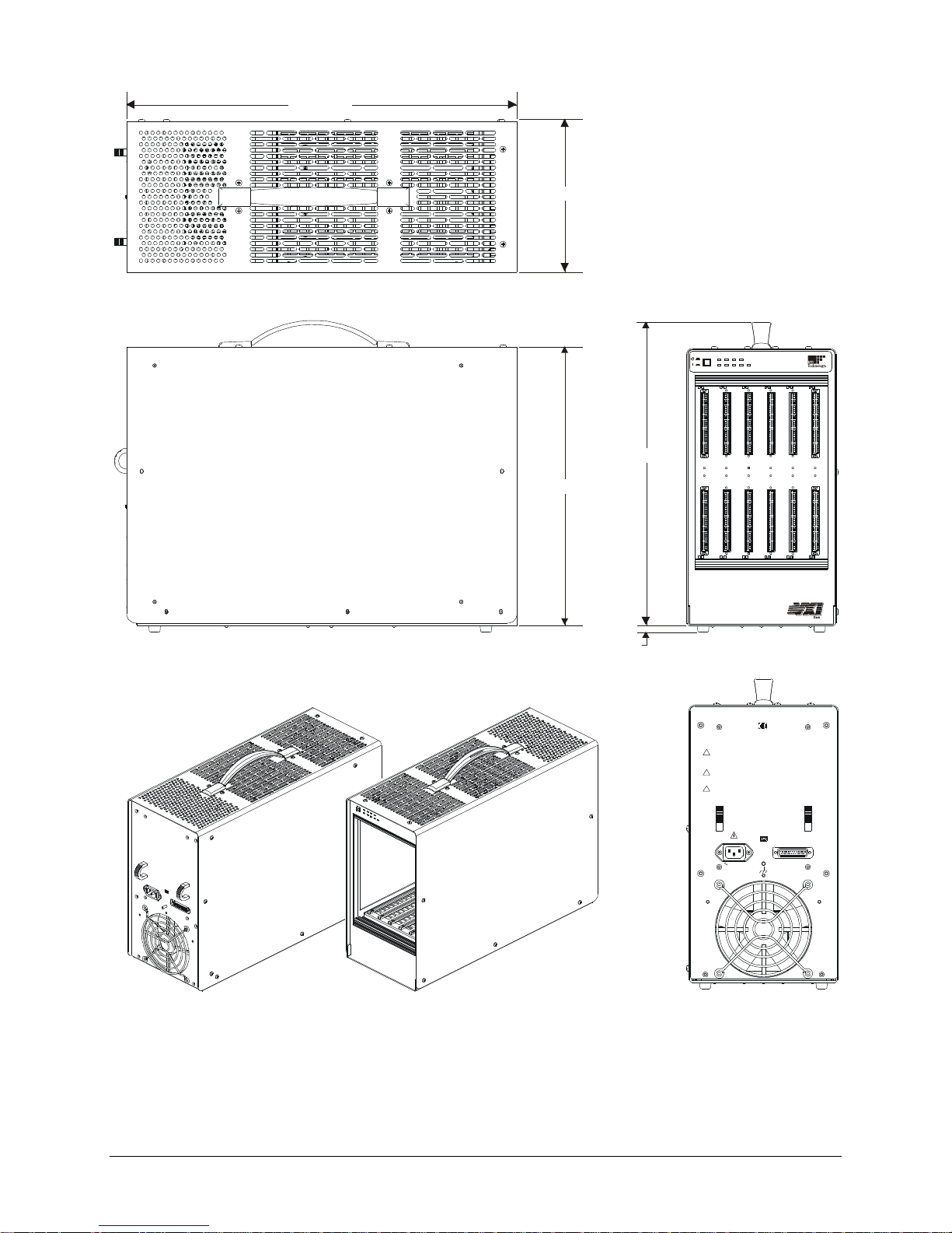
6.96" (176.78 mm) W x 15.00" (381.00 mm) H x 21.3" D (541.02 mm)
Six C-size VXIbus card slots (see Figure 1-6 for details)
WEIGHT
22 lb / 10 kg
VXIBUS VERSION
2.0
MTBF
100,000 hr
MTTR
5 min
ENVIRONMENTAL SPECIFICATIONS
OPERATING LOCATION
This chassis should be operated indoors in a controlled environment, protected
from exposure to the elements (i.e. direct sunlight, precipitation, wind, etc.).
Pollution degree 2. Installation Category II.
TEMPERATURE
Operating
Storage
0 C to +55 C
-40 C to +70 C
HUMIDITY
Operating
Non-operating
Up to 95% (non-condensing) at up to 30 °C; up to 45% at up to 55 °C
Up to 95% (non-condensing) at up to 55 °C
ALTITUDE
Operating
Non-operating
15,000 ft (4,570 m)
40,000 ft (12,190 m)
RANDOM VIBRATION*
Operating
Non-operating
0.27 g-rms total from 5 Hz to 55 Hz
2.28 g-rms total from 5 Hz to 55 Hz
* Three axis, 30 min total, 10 min per axis.
FUNCTIONAL SHOCK
Operating
Half sine, 30 g, 11 ms duration
Meets functional shock requirements of MIL-T-28800E, Type III, Class 5
Page 16

VXI Technology, Inc.
16 CT-100C Introduction
POWER SPECIFICATIONS
USEABLE POWER
500 W to 50 °C, derated by 2.5%/ °C above 50 °C
DC SUPPLY VOLTAGE
Voltage
Peak
Current
(IMP)
Dynamic
Current
(IMD)
Allowed Variation
Ripple/Noise
DC Load
Induced
Ripple
Noise
+5 V
40 A
5 A
+0.25 V / -0.125 V
50 mV
50 mV
-5.2 V
10 A
5 A
-0.26 V / +0.125 V
50 mV
50 mV
-2 V
8 A
2 A
-0.10 V / +0.72 V
50 mV
50 mV
+12 V
8 A
2 A
+0.60 V / -0.36 V
50 mV
50 mV
-12 V
4 A
2 A
-0.60 V / +0.36 V
50 mV
50 mV
+24 V
4 A
2 A
+1.20 V / -0.72 V
150 mV
150 mV
-24 V
4 A
2 A
-1.20 V / +0.74 V
150 mV
150 mV
POWER INPUT
Input Voltage / Freq.
Nominal AC
Inrush Current
Input Power
Input Leakage
Input Harmonics
Fuse
Minimum 100 V ac to a maximum 240 V ac, 50 Hz/60 Hz
< 40 A (cold start)
10 A max
< 1.24 MA @ 264 V ac, 53 Hz
Meets EN61000-3-2
Internal and independent of line voltage (not user accessible)
POWER SUPPLIES
UL, CSA, TUV approved, CE marked
Shout circuit, over-voltage, reverse voltage and thermal shutdown protection
COOLING SPECIFICATIONS
COOLING REQUIREMENTS*
Low Fan Speed
High Fan Speed
56 W/slot for a 10°C Rise
84 W/slot for a 15°C Rise
80 W/slot for a 10°C Rise
120 W/slot for a 15°C Rise
*Calculated using VXI-8 Rev. 2.0 standards
COOLING MODES
High or low speed cooling modes can be selected by moving the Fan Speed
switch at the rear of the chassis. The power supply and modules are cooled by
separate fans.
AIR FLOW PATH
Air is drawn into the chassis from the rear and is pressurized below the cards.
The air is then distributed across all slots along the total length of each slot and is
exhausted through the top of the mainframe. When the mainframe is rack
mounted, allow approximately 2 inches (50 mm) of clearance at the top and rear
for proper airflow.
ACOUSTIC NOISE
High Speed Fan Mode < 40 dBA
Low Speed Fan Mode < 30 dBA
Page 17
www.vxitech.com
CT-100C Introduction 17
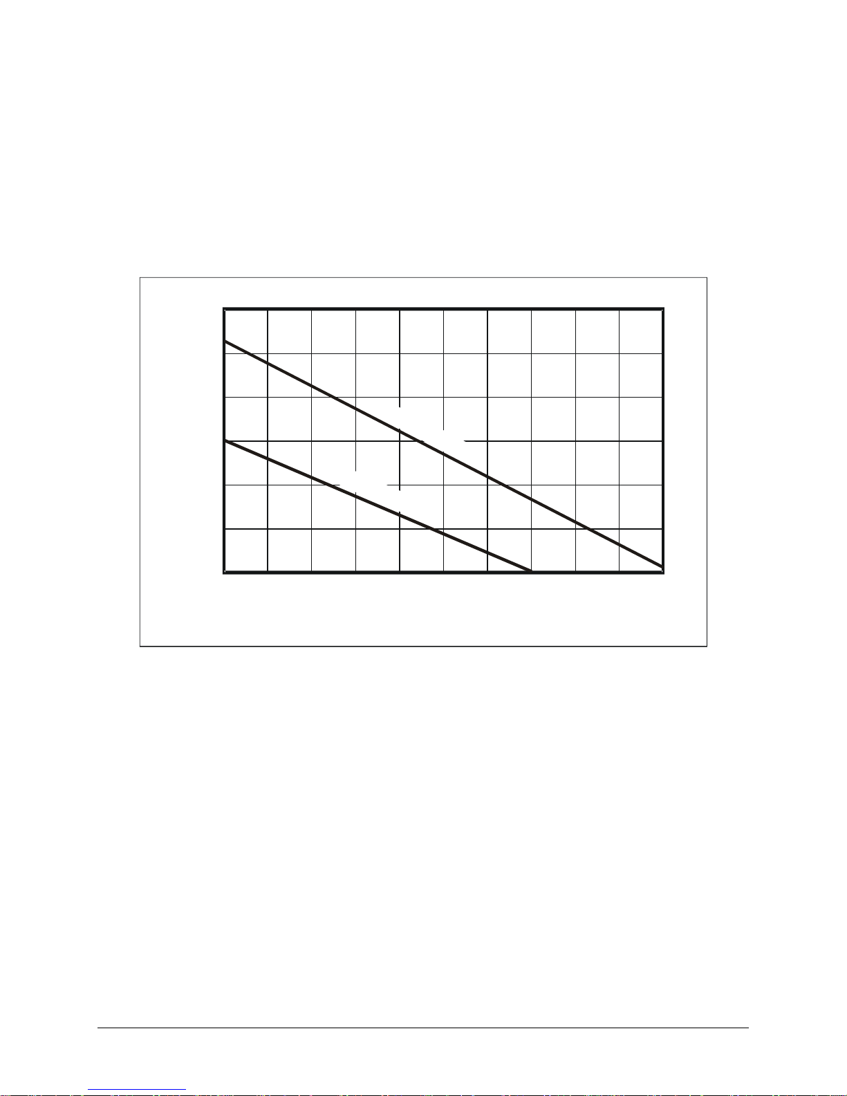
* Covers all slots, unrestricted
0.0
1.0
2.0
0 2.0 4.0 6.0 8.0 10.0
0.5
1.5
2.5
Pressure Drop - mm H
2
O
Airflow - liters/s
3.0
F
a
n
a
t
H
i
g
h
S
p
e
e
d
F
a
n
a
t
L
o
w
S
p
e
e
d
FIGURE 1-6: COOLING CAPACITY FOR CT-100C
Page 18
VXI Technology, Inc.
18 CT-100C Introduction
8.100 (205.74)
21.000 (533.40)
0.343 (8.71)
16.425 (417.20)
14.979 (380.47)
VXI Technology
FAN SPEED
HIGH / LOW
J201
MONITOR / CONTROL
100-240 VAC
10A MAX.
47 - 63 Hz
J200
WARNING - TO PREVENT POSSIBLE ELECTRIC SHOCK HAZARD, DISCONNECT POWER
CORD BEFORE REMOVING THE POWER SUPPLY MODULE FROM THE MAINFRAME.
ATTENTION - POUR EMP Ê CHER LE RISQUE POSSIBLE DE D É CHARGE É LECTRIQUE,
DEBRANCHER LE CORDON DE SECTEUR AVANT D'ENLEVER LE MODULE
D'ALIMENTATION D' É NERGIE DE L'UNIT É CENTRALE.
WARNING - FOR PROTECTION FROM ELECTRIC SHOCK, THE GROUNDING CONNECTION
IN THE POWER CORD MUST BE PROPERLY CONNECTED.
ATTENTION - POUR LA PROTECTION CONTRE LE CHOC É LECTRIQUE , LA PRISE DE
TERRE AU SOL DANS LE CORDON DE SECTEUR DOIT Ê TRE CORRECTMENT RELI É E.
WARNING - NO OPERATOR SERVICEABLE PARTS INSIDE. REFER SERVICING TO
TRAINED SERVICE PERSONNEL.
ATTENTION - AUCUNES PI È CES REPARABLES PAR UN OP É RATEUR À L'INT É RIEUR.
R É F É REZ L'ENTRETIEN AU PERSONNEL QUALIFI É.
!
!
!
0 1 2 3 4 5
Voltage Monitors Power
+5V +12V +24V +5V Stby
-5.2V -12V -24V -2V FAN
CT-100C
VXI Mainframe
Note: Dimensions in parentheses are in millimeters.
FIGURE 1-7: CT-100C DIMENSIONAL DIAGRAM
Page 19

www.vxitech.com
CT-100C Installation 19
SECTION 2
INSTALLATION
INTRODUCTION
When the CT-100C is unpacked from its shipping carton, the contents should include the following
items:
(1) CT-100C Six-Slot Chassis
(1) CT-100C Module User’s Manual (this manual)
(1) Power cord
All components should be immediately inspected for damage upon receipt of the unit.
BACKPLANE
The CT-100C mainframe has a jumper-less, auto-configurable backplane using active-automatic
daisy chaining for the VME Interrupt acknowledge and bus grant daisy chain signal lines. This
eliminates the need to manually configure the backplane and insures that these signals are properly
configured at all times.
The power cord is the only way to disconnect the CT-100C mainframe from ac power.
Therefore, the power cord must be accessible to the operator at all times. When the CT-100C
mainframe is mounted in a system rack, the power cord need not be accessible since the rack
must have its own disconnect device.
Le cordon de secteur est la seule manière de démonter l’unité centrale de CT-100C du
courant alternatif Par conséquent, le cordon de secteur doit être accessible à l’opérateur à
tout moment. Quand l’unité centrale de CT-100C est montée dans un support de système, le
cordon de secteur n’a pas besoin d’être accessible puisque le support doit avoir son propre
dispositif de débranchement.
Page 20
VXI Technology, Inc.
20 CT-100C Installation
REMOTE POWER-ON OPTION
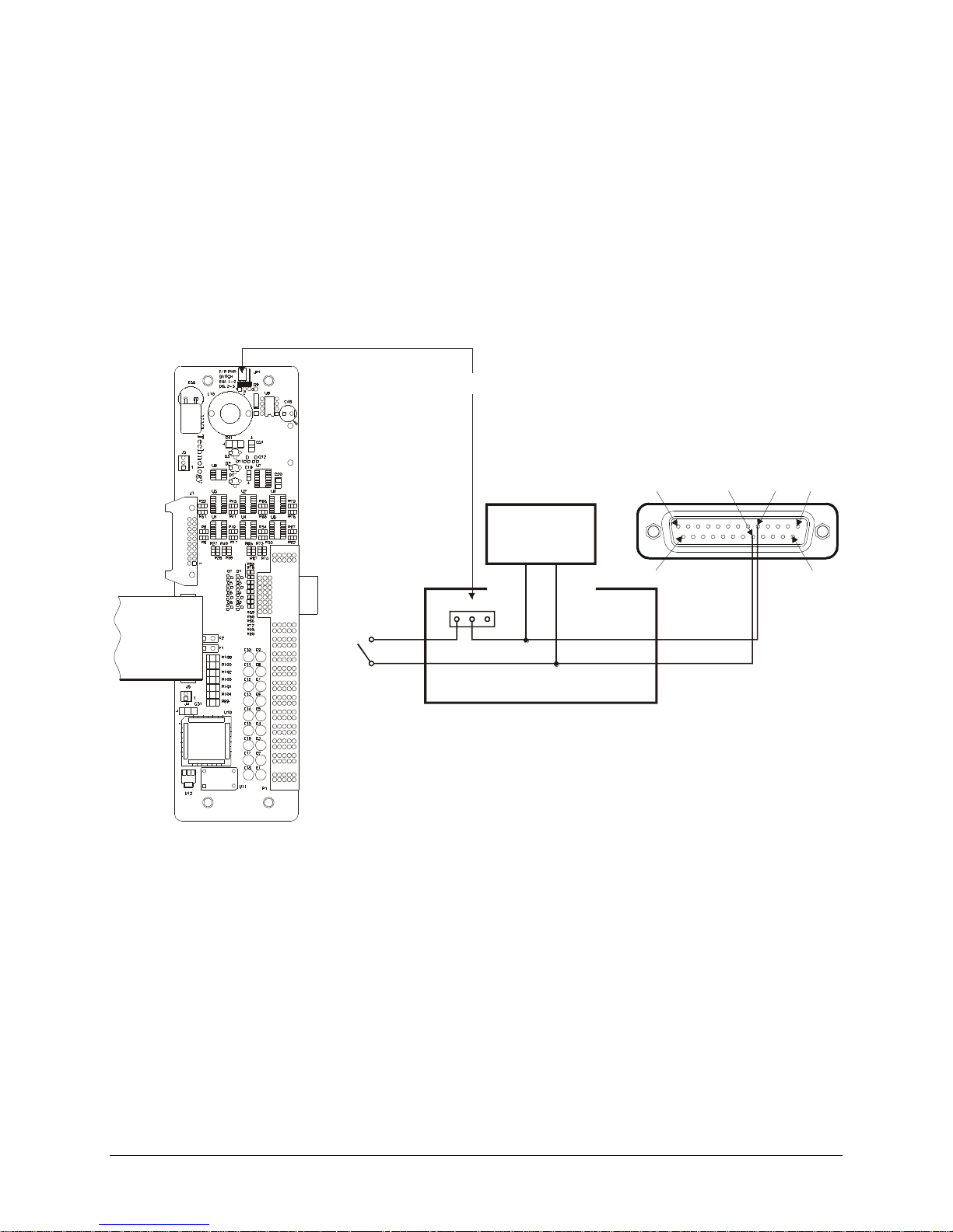
If the CT-100C mainframe is to be installed in a remote location, it is possible to apply and remove
power from the unit via the remote power pins located on connector J201. To utilize the remote
power feature, set the front panel switch to the standby position. Remove the power cord, then
remove the power supply from the chassis and place the jumper on the power interface board to the
2 – 3 position (see Figure 2-1 for power supply removal instructions). The power interface board
will be located inside the mainframe at the top right. Doing this will disable the front panel power
switch. Pins 5 and 18 can now be used to remotely control the powering of the chassis. The circuit
is diagramed below:
Power Interface Board
Pin 13 Pin 1
Pin 5Pin 18
Pin 25
Power Interface Board
Front
Panel
Switch
1 2
3
Pin 18
Pin 5
Pin 14
Power
Supply
Jumper Location
FIGURE 1-1: REMOTE POWER-ON SWITCH WIRING
Page 21
www.vxitech.com
CT-100C Installation 21
+5 V STANDBY USAGE
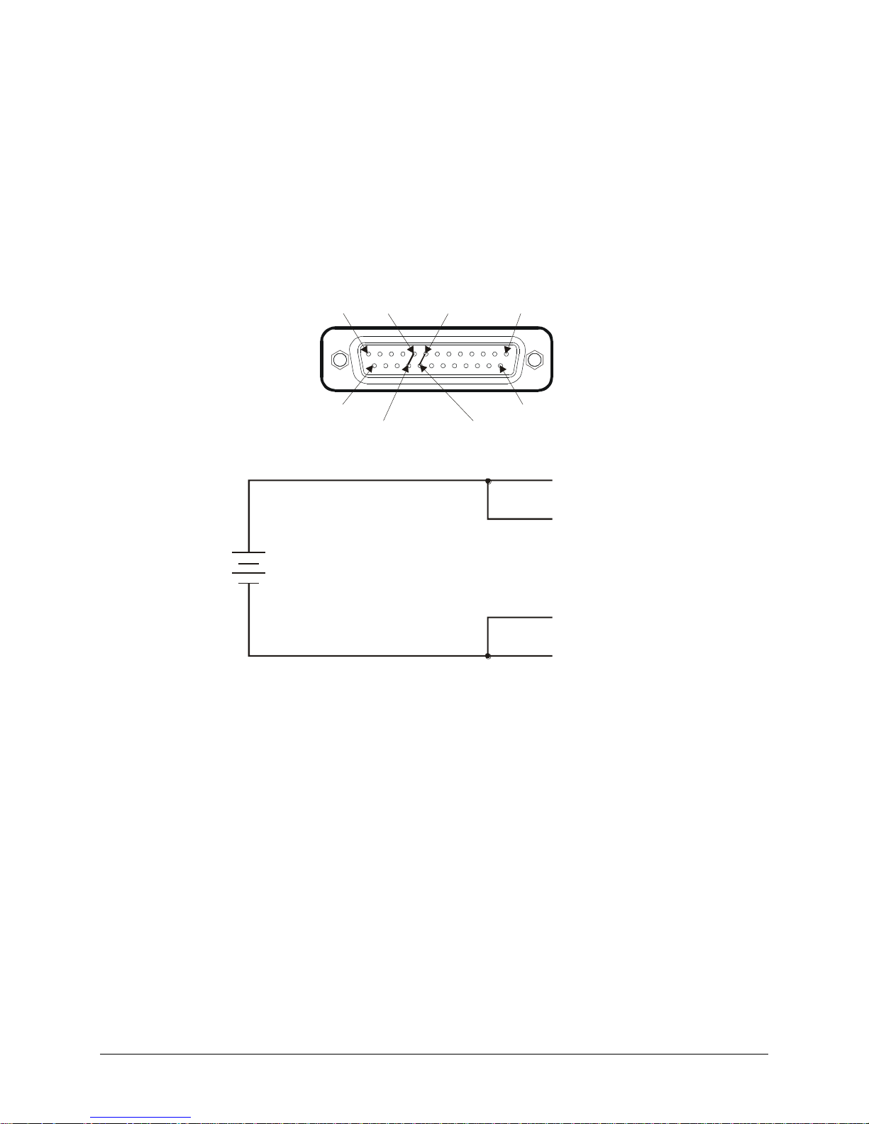
To prevent timers and other circuits from loosing power when the CT-100C is in standby mode,
+5 V Standby pins are made available on connector J201. An external power source can be wired
to these pins with a maximum allowed current of 1 A total across Pins 8 and 21, as these pins are
wired in parallel.
Pin 13 Pin 1
Pin 8
Pin 21
Pin 25
Pin 14
Pin 9
Pin 22
Pin 8 (+5 V Standby)
Pin 9 (+5 V Standby Return)
External
+5 V Standby
Power Source
Pin 21 (+5 V Standby)
Pin 22 (+5 V Standby Return)
FIGURE 1-2: +5 V STANDBY WIRING DIAGRAM
Page 22
VXI Technology, Inc.
22 CT-100C Installation
FAN SPEED SWITCH
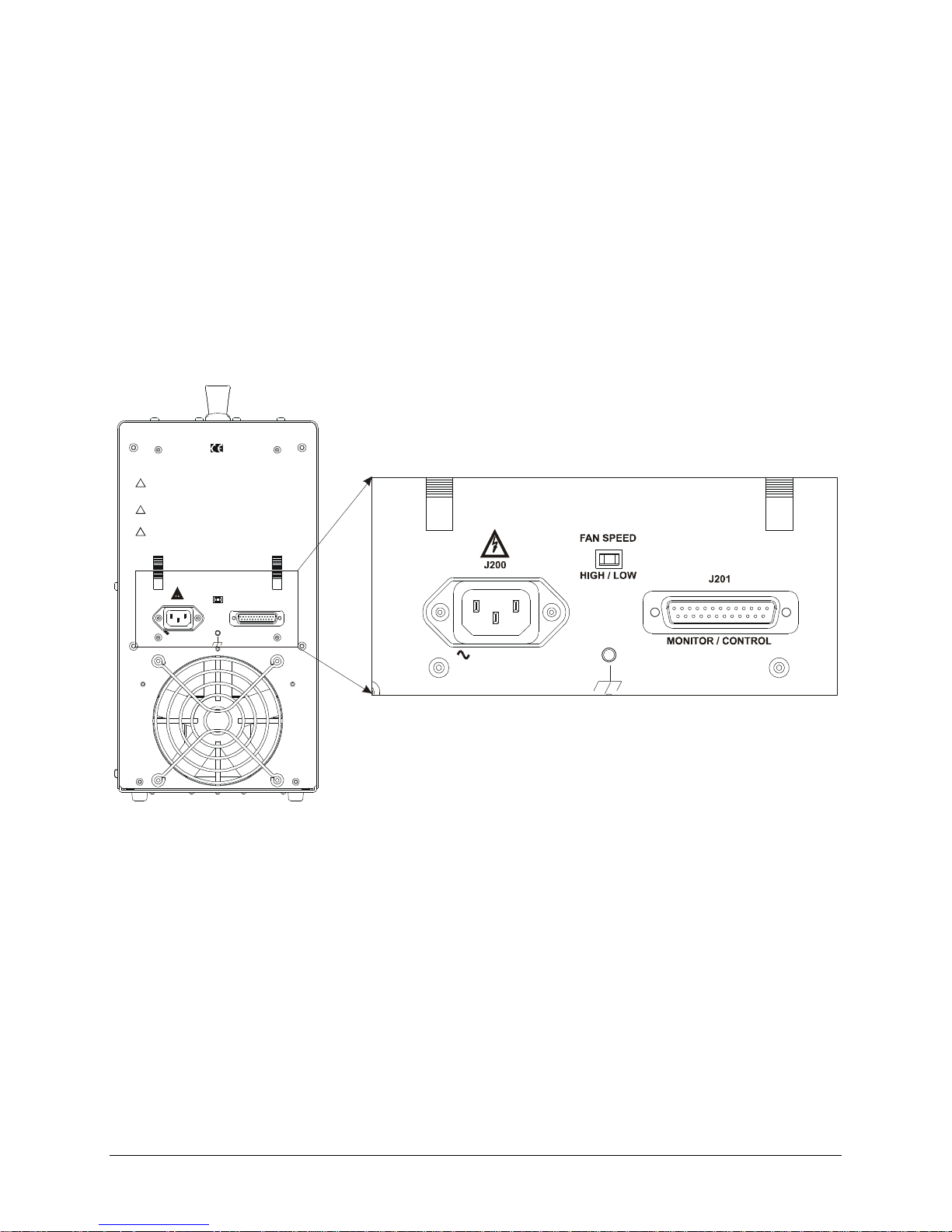
A fan speed selector switch is located at the rear of the CT-100C chassis. To set the fans to operate
at HIGH speed, move the switch at the rear of the chassis to the left. At HIGH speed, the chassis is
provided maximum cooling to the instruments.
The fans will operate in the LOW speed mode when the fan speed switch is toggled to the right.
The low speed mode provides for quieter operation, but decreases the cooling capability of the
fans. To best determine which mode of operation is best in a given application, refer to Figure 1-6
on page 17 that delineates the cooling requirements of populated mainframes. If all instruments
installed in the chassis receive adequate cooling in the low speed mode, then this mode may be
used.
VXI Technology
HIGH / LOW
WARNING - TO PREVENT POSSIBLE ELECTRIC S HOCK HAZARD, DISCONN ECT POWER
CORD BEFORE REMOVING THE POWER SU PPLY MODULE FROM THE M AINFRAME.
ATTENTION - POUR EMP Ê CHER LE RISQUE POSSIBLE DE D É CH ARGE É LECTRIQU E,
DEBRANCHER LE C ORDON DE SECTEUR AVANT D'ENLEVER LE MODULE
D'ALIMENTATION D' É NERGIE DE L'UNIT É CENTRA LE.
WARNING - FOR PROTECT ION FROM ELECTRIC SHOCK, THE GROU NDING CONNECTION
IN THE POWER CORD MUST BE PROPERLY CONN ECTED.
ATTENTION - POUR LA PROT ECTION CONTRE LE CH OC É LECTRIQUE , LA PRISE DE
TERRE AU SOL DANS LE C ORDON DE SECTEU R DOIT Ê TRE CORRECTMENT RE LI É E.
WARNING - NO OPERATOR SER VICEABLE PARTS INSIDE. REFE R SERVICING TO
TRAINED SERVICE PER SONNEL.
ATTENTION - AUCUNES PI È CES REPARABLES PAR UN OP É RATEUR À L'INT É RIEUR.
R É F É REZ L'ENTRETIEN AU PERSO NNEL QUALIFI É.
!
!
!
Fan Speed Switch Location
(Rear Panel of CT-100C Mainframe)
100-240 VAC
10A MAX.
47 - 63 Hz
100-240 VAC
10A MAX.
47 - 63 Hz
J200
FAN SPEED
HIGH / LOW
J201
MONITOR / CON TROL
FIGURE 1-3: FAN SPEED SWITCH LOCATION
Page 23

www.vxitech.com
CT-100C Installation 23
RACKMOUNT OPTION INSTALLATION
OVERVIEW
This section contains the procedures for installing a CT-100C chassis in a standard 19” relay rack.
The available rackmounting options are:
Option 59 – Rackmount Ear Kit
Option 60 – Rackmount Door Kit
Option 63 – 20” Slide Kit
Option 64 – 24” Slide Kit
Option 65 – Acrylic Rackmount Door Kit
The rackmount ear kit provides the basic hardware necessary to rackmount the CT-100C chassis
and must be purchased to install any other rackmounting options. Because the chassis is only 15”
wide, standard rack support rails cannot provide mechanical support to the chassis. If the
equipment mounted below the CT-100C cannot provide mechanical support to the chassis, either
20” or 24” slides will be required to support the chassis in the rack. The rackmounting ears are
designed to allow the chassis to be flush mounted in the rack or recessed 4”.
The rackmount door kit provides the necessary hardware to install either a 1/8” thick aluminum
door or a 1/8” thick acrylic door in front of the rackmounted chassis. These options require that the
rackmount ear kit also be installed and configured for recessed mounting. The door may be
customer modified to hold connectors, controls, indicators, and similar components.
The 20” and 24” slide kits provide the ability to easily remove the chassis from the rack for
servicing and provides mechanical support for the chassis when installed in the rack. The 20” slide
kit is used when the chassis is flush mounted in the rack. If the chassis is to be recess mounted,
then the 24” slides are required.
Page 24

VXI Technology, Inc.
24 CT-100C Installation
RACKMOUNT KIT INSTALLATION
The rackmount kit (Option 59) provides the basic hardware necessary to rack mount the CT-100C
chassis. With the chassis being only 15” wide, standard rack support rails cannot provide
mechanical support to the chassis. If the equipment mounted below the CT-100C cannot provide
mechanical support to the chassis, either 20” or 24” rack slides will be required to support the
chassis when installed into the rack. The rackmounting ears are designed to allow the chassis to be
flush mounted in the rack or recessed 4”.
Required Tools
1. #2 Phillips Screwdriver
Parts List
QTY
ITEM
VTI P/N
4
Screw, 6-32 x 1/2", Phillips/Sems
37-0028-050
1
Bracket, Rack Flange w/ hinge mounting holes
41-0135-000
1
Bracket, Rack Flange
41-0135-001
Assembly Procedure
1. Remove the four (4) black plastic feet from the bottom of the chassis.
2. Lay the chassis on a protected work surface on its long side with the voltage monitor LEDs of
the chassis facing front with the power switch toward the top.
3. Locate and remove four black plastic feet on the side of the chassis and four black plastic feet
on the bottom of the chassis. Retain the feet if restoring the chassis to its original portable use
is anticipated.
4. Find two threaded holes on each side of the chassis (the plastic feet were attached to two of
these holes) towards the front of the unit.
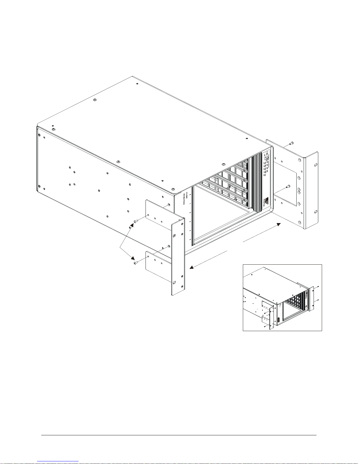
5. Line up the rackmount ears with the threaded holes selecting the flush or recessed position as
desired. Refer to the rackmount ear Figure 1-4 for visual assistance.
6. Secure the rack ears using the supplied #8-32 hardware.
Before installing the chassis into an EIA switch rack, the chassis handle should be removed. This
can be done by doing the following:
1. Remove the four screws located near the handle.
2. Remove the two black decorative covers at each end of the carrying handle using the flat blade
screwdriver. Place a piece of paper under the screwdriver blade to prevent scratching the
chassis cover.
3. Remove the four Phillips screws holding the handle in place and then remove the handle itself.
Retain the carrying handle components if there may be some need to restore the chassis to its
original portable use in the future.
Page 25
www.vxitech.com
CT-100C Installation 25
Black Oxide
Pan Head
Phillips Screws (x4)
Rack Mount Ears (x2)
Flush Rackmount Configuration
* Recessed Rackmount Installation Shown
FIGURE 1-4: RACKMOUNT EAR INSTALLATION DIAGRAM
Page 26
VXI Technology, Inc.
26 CT-100C Installation
RACK SLIDE INSTALLATION (20” AND 24”)
The 20” and 24” slide hardware kits (Options 63 and 64, respectively) provide standard flanges to
mount the slides into standard EIA relay racks. It should be noted that the slide flanges in the front
should be installed behind the rack’s front panel mounting rails. This will allow the rackmounting
ears to sit flush with the front of the rack. It should also be noted that although the hardware
provided in this kit will provide all the necessary components to successfully install the CT-100C
into a rack, there are many variations in how EIA relay racks are designed and additional adapter
hardware may be required to install the chassis. Please refer to the relay rack manufacture’s catalog
for additional options.
This procedure provides instructions for installing the 20” or 24” slide kits. Note that the 20” and
24” slide kits are identical except for the length of the slide units. A 20” slide kit is used when the
chassis is flush mounted and a 24” slide kit is used when the chassis is recess mounted. Note,
Option 59 must be purchased and installed prior to installing the rack slides.
Required Tools
1. #2 Phillips Screwdriver
2. 1/8" Flat Blade Screwdriver
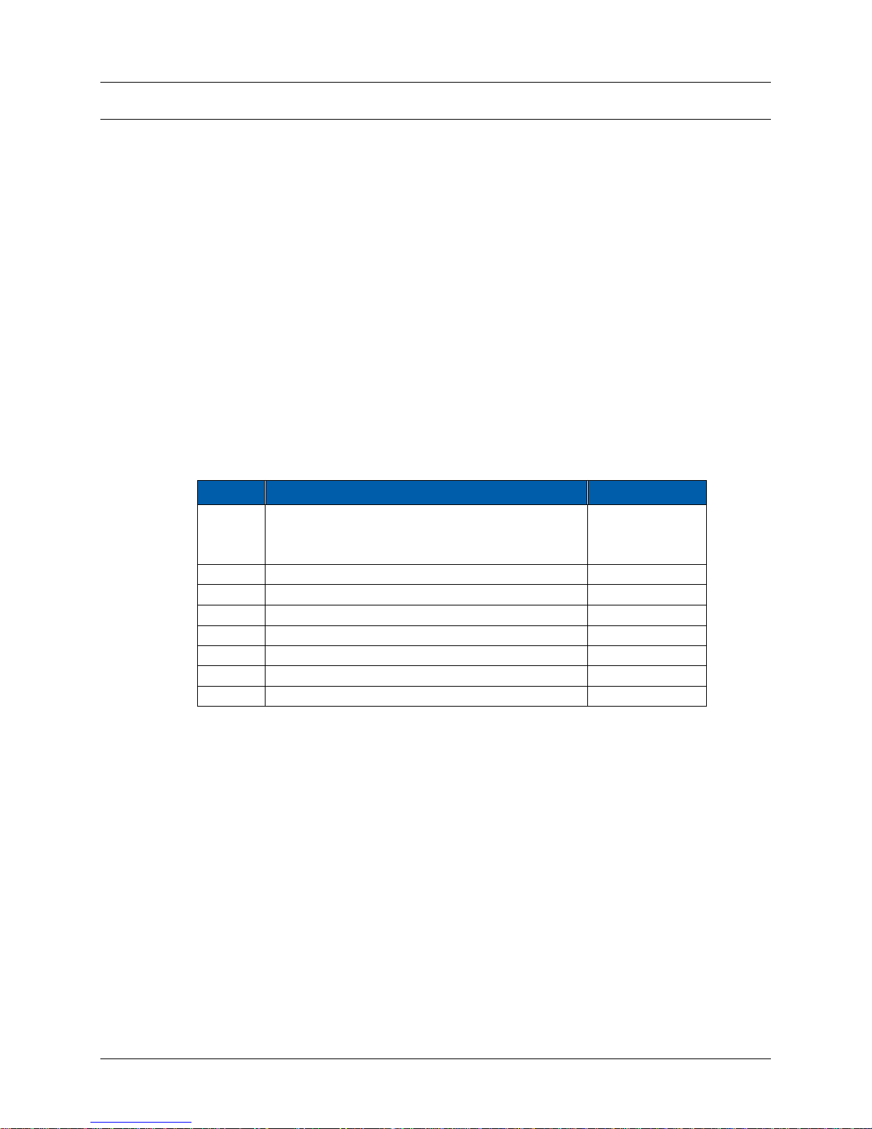
Parts List
QTY
ITEM
VTI P/N
2
Slide, Rack Mount, Steel, 20”
37-0054-020
- or -
2
Slide, Rack Mount, Steel, 24”
37-0054-024
1
Hardware Kit, Rack Mount Slide, Steel
37-0055-000
6
Screw, 8-32 x 3/8” Pan Head Phillips, Sems Zinc
37-0073-037
6
Screw, 8-32 x 1/4” Pan Head Phillips, Steel/Zinc
37-0074-025
4
Screw, 8-32 x 3/8”, F/H Undercut Phillips, Zinc
37-0115-037
2
Bracket, Slide, Front
41-0108-000
1
Bracket, Slide, Top Side
41-0131-000
1
Bracket, Slide, Bottom
41-0132-000
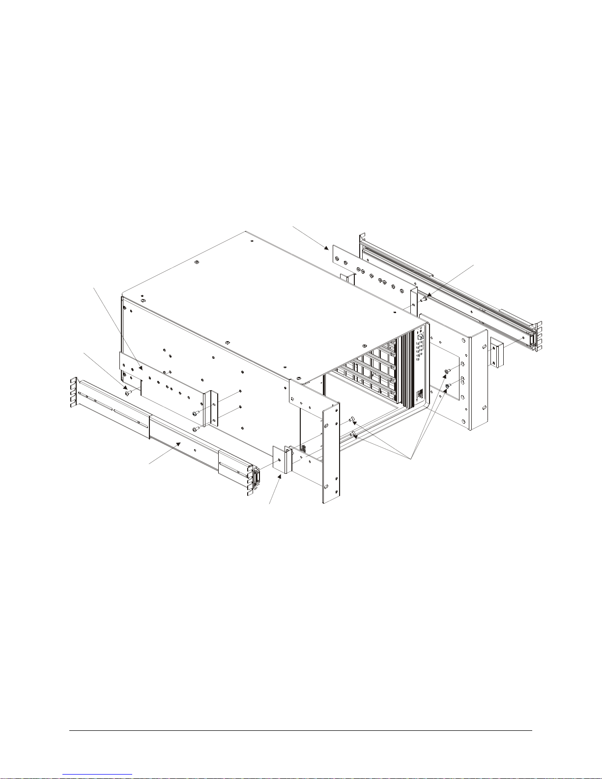
Assembly Instructions
1. Lay the chassis on a protected work surface on its long side with the voltage monitor LEDs of
the chassis facing front with the power switch toward the top.
2. If the rackmount ears were installed flush, remove the rackmount ears and install the front
slide bracket to them as shown in the assembly drawing using a flat head screw driver. If the
rackmount ears were installed recessed, simply install the slide brackets onto the ears as
shown on the following page.
3. Reinstall the rackmount ears (if necessary).
4. Install the top and bottom slide brackets using 1/4” Phillips pan head screws. Note that the
slide mounting holes should be oriented below the centerline of the chassis.
Page 27
www.vxitech.com
CT-100C Installation 27
5. Locate the slide hardware kit provided. Install the rack flanges to the slides as required by the
application using the hardware in the kit. Note that the screws are inserted from the inside of
the slides and the nuts would show on the outside.
6. Install the slides to the mounting brackets already installed on the chassis using the provided
hardware.
Slide Bracket, (x2) Front
Slide Bracket, Top
Slide Bracket, Bottom
1/4” Pan Head
Phillips Screw (x3)
Rack Mount Slide (20” or 24”)
Hardware Kit
3/8” Pan Head Phillips Screws (x6)
1/4” Pan Head
Phillips Screw (x3)
3/8” Undercut Flathead
Phillips Screws (x4)
* Recessed rack slide configuration shown
FIGURE 1-5: RACK SLIDE INSTALLATION DIAGRAM
Page 28
VXI Technology, Inc.
28 CT-100C Installation
RACKMOUNT DOOR KIT INSTALLATION
The rackmount door kit (Option 60) provides the necessary hardware to install a 1/8” thick
aluminum door in front of the rackmounted chassis. This option requires that the rackmount ear kit
(Option 59) also be purchased, installed, and configured for recessed mounting. The door may be
modified by the customer to hold connectors, controls, indicators, and similar components.
Required Tools
1. #2 Phillips Screwdriver
2. 1/8" Flat Blade Screwdriver
3. 11/32" Open Ended Wrench
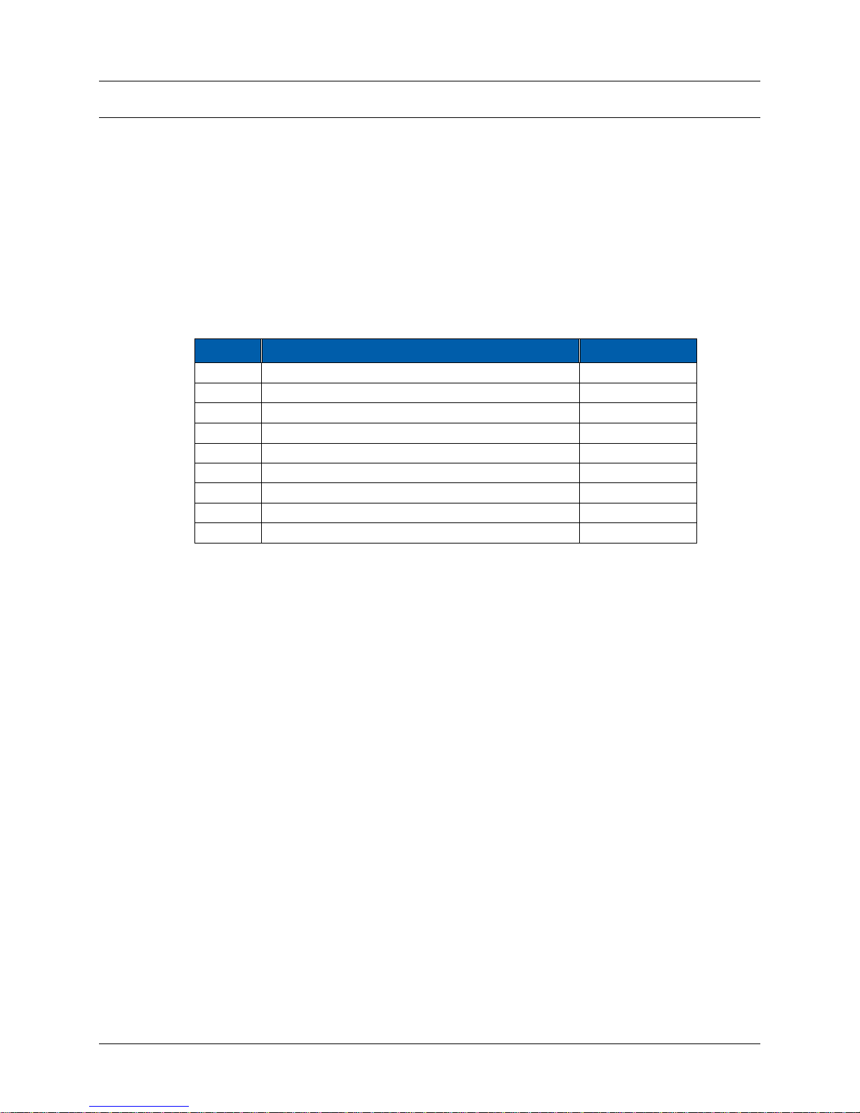
Parts List
QTY
ITEM
VTI P/N
2
Screw, 6-32 x 1/2” Pan Head Ph, Sq Cone Sems Zinc
37-0028-050
2
Nut, Hex, 6-32, Zinc/Steel
37-0030-632
1
Latch, Vise Action, Know Style, Black
37-0065-000
2
Hinge, Adjustable Damping, Black
37-0066-000
8
Screw, 8-32 x 3/8” Pan Head Phil, M/S, Blk Zinc
37-0079-037
4
Screw, 8-32 x 3/8” Flat Head Phillips, Zinc
37-0080-037
1
Latch, Door, Rackmount, CT-100C
41-0133-000
1
Door, Front, Rackmount, CT-100C
41-0134-000
2
Brace, Rackmount, CT-100C
41-0136-000
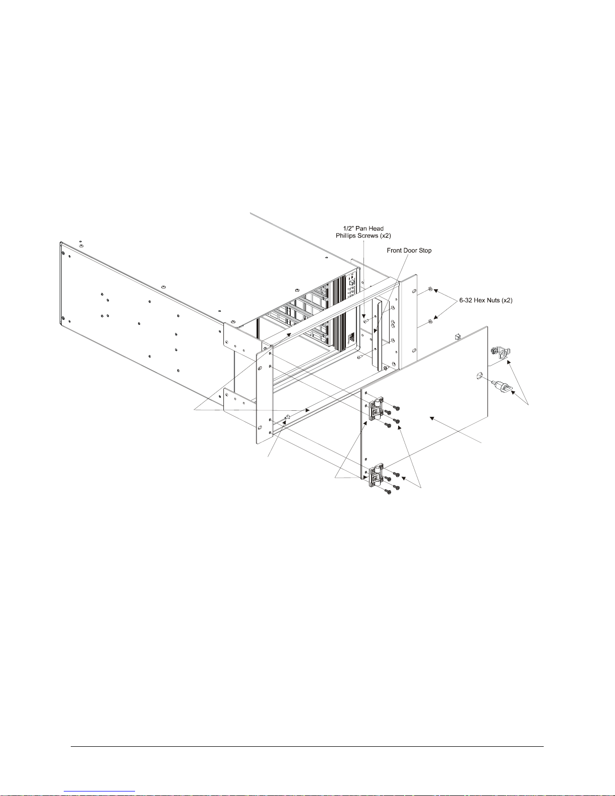
Assembly Procedure
1. Lay the chassis on a protected work surface on its long side with the voltage monitor LEDs of
the chassis facing front with the power switch toward the top.
2. Locate two rackmount (cross) braces. Install one each along the front of the flanges (one on
top and one on the bottom) using four (two ea.) #8 flathead screws. The lip along the long
edge of each brace goes toward the front and pointing inside. The braces fit over the flanges
and the screws are placed from the inside going through the flange and then into the brace.
3. Locate the front door and two hinges. Install the two hinges to the front door using four black
screws provided.
4. Locate the latch kit and install it into the door from the side where the hinges are mounted.
5. Locate the door latch bracket and install it on the rackmount ear opposite the end where the
hinges will be installed. Use Figure 1-6 as a reference.
6. Locate the four tapped holes on the front surface of the rackmount ear to which the door is to
be attached.
7. Install the door by its hinges to the rackmount ear using four black screws provided with the
option kit.
8. Test that the door opens and closes smoothly and adjust the latch as necessary to secure the
door when latched close.
Page 29
www.vxitech.com
CT-100C Installation 29
Hinges (x2)
3/8” Flat Head
Phillips Screws (x4)
Rackmount Braces (x2)
3/8” Pan Head Black Oxide
Phillips Screws (x8)
Front Door, Aluminum
Door Latch Kit
FIGURE 1-6: RACK DOOR INSTALLATION DIAGRAM
Page 30
VXI Technology, Inc.
30 CT-100C Installation
ACRYLIC RACKMOUNT DOOR KIT INSTALLATION
An acrylic rackmount door is offered as an alternative to the aluminum rackmount door. The kit
(Option 65) provides the necessary hardware to install a 1/8” thick acrylic door in front of the
rackmounted chassis. An installation diagram is provided on the following page for ease of
assembly. This option requires that the rackmount ear kit (Option 59) be purchased, installed, and
configured for recessed mounting.
Required Tools
1. #2 Phillips Screwdriver
2. 1/8" Flat Blade Screwdriver
3. 11/32" Open Ended Wrench
Parts List
QTY
ITEM
VTI P/N
2
Screw, 6-32 x 1/2" Pan Head Phillips, Sems Zinc
37-0028-050
2
Nut, Hex, 6-32, Zinc/Steel
37-0030-632
1
Latch, Vise Action, Knob Style, Black
37-0065-000
2
Hinge, Adjustable Damping, Black
37-0066-000
4
Screw, 8-32 x 3/8" Pan Head Phillips, Black Oxide
37-0079-037
1
Stop, Front Door, CT-100C
41-0133-000
1
Door, Front, CT-100, Acrylic
41-0303-000
2
Brace, Rackmount, CT-100C
41-0136-000
4
Nut, Hex, 8-32, Zinc/Steel
37-0030-832
4
Washer, Split Lock, 8-32 Zinc
37-0013-008
4
Washer, Flat 8-32, Zinc
37-0012-008
4
Screw, 8-32 x 1/2" Pan Head Phillips, Black Oxide
37-0079-050
4
Screw, 8-32 x 3/8" Flat Head Phillips, Zinc
37-0080-037
Assembly Procedure
1. Lay the chassis on a protected work surface on its long side with the voltage monitor LEDs of
the chassis facing front with the power switch toward the top.
2. Locate two rackmount (cross) braces. Install one each along the front of the flanges (one on
top and one on the bottom) using four (two ea.) #8 flathead screws. The lip along the long
edge of each brace goes toward the front and pointing inside. The braces fit over the flanges
and the screws are placed from the inside going through the flange and then into the brace.
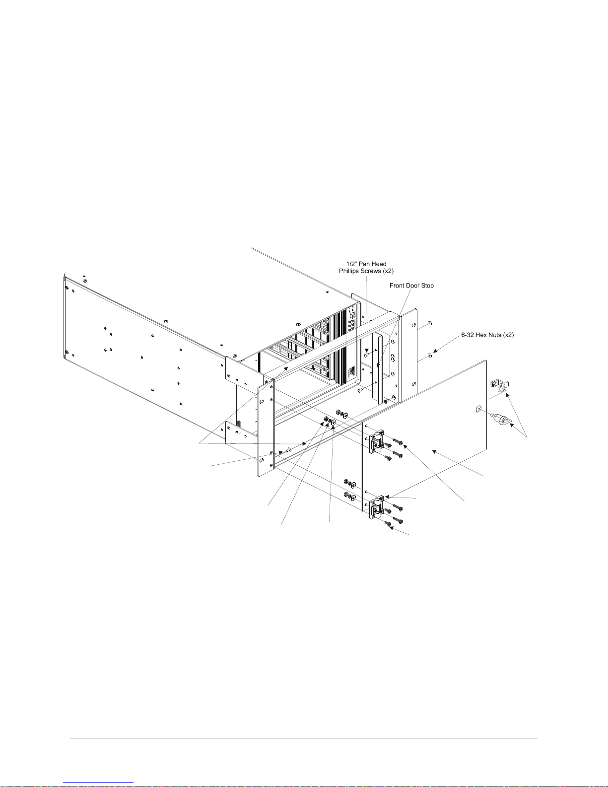
3. Locate the front door and two hinges. Install the two hinges to the front door using four 1/2”
black oxide pan head screws through the holes of the hinge with the flat washer in contact with
the door and with the split lock washer between the hex nut and the flat washer.
4. Locate the latch kit and install it into the door from the side where the hinges are mounted.
5. Locate the door latch bracket and install it on the rackmount ear opposite the end where the
hinges will be installed. Use Figure 1-7 as a reference.
6. Locate the four tapped holes on the front surface of the rackmount ear to which the door is to
be attached.
Page 31
www.vxitech.com
CT-100C Installation 31
7. Install the door by its hinges to the rackmount ear using four 3/8” black pan head screws
provided with the option kit.
8. Test that the door opens and closes smoothly and adjust the latch as necessary to secure the
door when latched close.
Hinges (x2)
3/8” Flat Head
Phillips Screws (x4)
Rack Mount Braces (x2)
1/2” Pan Head Black Oxide
Phillips Screws (x4)
3/8” Pan Head Black Oxide
Phillips Screws (x4)
8-32 Hex Nuts (x4)
8-32 Split Lock Washer
8-32 Flat Washer
Front Door, Acrylic
Door Latch Kit
FIGURE 1-7: ACRYLIC RACK DOOR INSTALLATION DIAGRAM
Page 32

VXI Technology, Inc.
32 CT-100C Installation
INSTALLATION OF VXI MODULES
OVERVIEW
After the successful installation of rackmount accessories, the chassis is ready for installation of
the VXIbus base units (i.e. an SMP1100, SMP1200, etc.). It is recommended that the instruments
be installed after rackmount accessories have been installed to avoid any unnecessary physical
strains that may be incurred during the installation of the accessories. Whether single- or doublewide, the process of installation is simple.
Required Tools
1. Slotted screw driver
Installation Procedure
Install C-size modules directly into the mainframe as follows:
1. To prevent damage to the module, insure the mainframe is powered off.
2. Insert the module into the mainframe by aligning it with both the upper and lower card guide
of the desired slot. The card guide for the module is the right, longer guide-pair of each guide
set.
3. Gently push the module into the slot until it seats into the backplane connectors. The front
panel of the module should be flush with mainframe.
4. Tighten the mounting screws at the top and bottom of the module.
Page 33

www.vxitech.com
CT-100C Installation 33
DISCONNECTING THE MAINFRAME
To disconnect the CT-100C from its installation, simply follow the instructions below:
1. Place the mainframe in standby by depressing the power switch.
2. Remove the power cord from the mainframe to ensure that no power is running to the
mainframe.
3. Remove all cabling associated with the VXI modules installed in the CT-100C.
4. If the chassis is rack mounted, remove the chassis from the rack by removing the screws that
attach the mainframe to the rack.
Rackmount options can be removed from the mainframe at this time if desired.
Page 34

VXI Technology, Inc.
34 CT-100C Installation
Page 35

www.vxitech.com
CT-100C Service Information 35
SECTION 3
SERVICE INFORMATION
INTRODUCTION
There are no operating instructions required for the CT-100C VXIbus chassis. After the chassis is
installed, operation is completely transparent to the operator. Just plug in the instruments then
power up the chassis.
NOTE Service should only be performed by qualified personnel.
Le service devrait seulement être assure par le personnel qualifié.
REPLICABLE PARTS LIST
The following table lists the parts that can be replaced on the CT-100C chassis.
Description
Part Number
Final Assembly, Power Supply Replacement Kit, CT-100C
70-0271-000
Page 36

VXI Technology, Inc.
36 CT-100C Service Information
CT-100C POWER SUPPLY REPLACEMENT
The CT-100C should operate without the need for service. In the event that the cooling fans or
power supply must be replaced, they are contained in a single, easy to remove module.
Replacement of the power supply can be accomplished as follows:
1. Remove the AC power cord from the chassis.
To avoid the possibility of shock, wait a minimum of ten seconds for electricity to dissipate
from the mainframe after removing power.
Pour éviter la possibilité de choc, attendez dix secondes au minimum affin que l’électricité se
dissipe l’unité centrale.
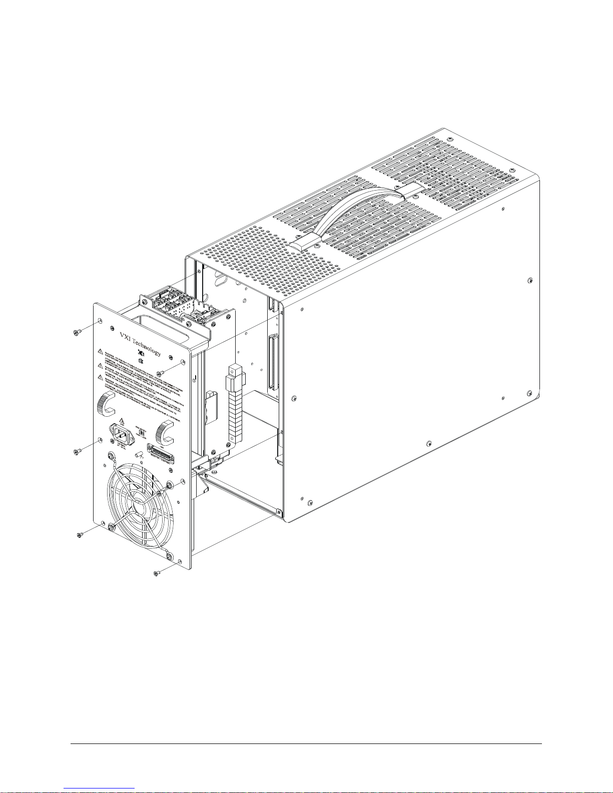
2. Locate the six screws at the rear of the chassis attaching the power supply to the mainframe
and remove all six.
3. Locate the two handles on the power supply and firmly pull the module straight back.
4. Locate the replacement power supply module and bring it up to the rear of the chassis.
5. Back the new power supply module into the rear of the chassis. Ensure that the connector on
the power supply is in line with the mating connector on the power interface board.
6. Seat the power supply module firmly in place and install the previously removed screws to
9.5 lbf/in (11.0 kgf/cm).
7. Verify that the front panel power switch is in the OFF position and reattach the power cord.
Page 37
www.vxitech.com
CT-100C Service Information 37
FIGURE 2-1: POWER SUPPLY REPLACEMENT DIAGRAM
Page 38

VXI Technology, Inc.
38 CT-100C Service Information
CLEANING THE MAINFRAME
During normal operation, dust is likely to accumulate inside the power supply of the CT-100C. To
remove this dust, power down the chassis and remove the power cord. Follow the instructions
provided on the previous page to remove the power supply from the mainframe. After removing
the power supply, use a pressurized air can to remove any dust present.
Page 39

www.vxitech.com
CT-100C Index 39
INDEX
Numerics
5V STANDBY ............................................................................ 12
usage ..................................................................................... 23
A
airflow ................................................................................... 12, 18
B
backplane .............................................................................. 12, 34
backplane configuration ................................ .............................. 12
base unit installation ................................................................... 34
C
card guide .................................................................................... 34
cleaning ....................................................................................... 40
D
disconnecting the mainframe ...................................................... 35
dynamic current .......................................................................... 18
F
fan speed ..................................................................................... 24
HIGH speed mode ................................................................. 24
LOW speed mode .................................................................. 24
fuse .............................................................................................. 18
J
J201 connector ............................................................................ 22
jumpering ................................................................ .................... 12
M
mainframe features ...................................................................... 14
MTBF .......................................................................................... 17
MTTR ......................................................................................... 17
P
peak current ................................................................................. 18
power supplies ............................................................................. 12
power supply replacement ........................................................... 38
R
rack mount .................................................................................. 25
rack mounting ............................................................................. 12
rack slide ..................................................................................... 25
rackmount ................................................................................... 13
remote power ............................................................................... 22
replicable parts ............................................................................ 37
S
specifications ........................................................................ 17, 18
cooling ................................................................................... 18
environmental ........................................................................ 17
general ................................................................................... 17
power ..................................................................................... 18
V
voltage ......................................................................................... 18
VXIbus ........................................................................................ 12
W
WEEE ............................................................................................ 6
 Loading...