

Page 1

VXIpc
NI-VXI
Getting Started with Your
™
-486 Model 200 Series and the
™
Software for Microsoft Windows
bus
July 1994 Edition
Part Number 320481-01
© Copyright 1994 National Instruments Corporation.
All Rights Reserved.
Page 2

National Instruments Corporate Headquarters
6504 Bridge Point Parkway
Austin, TX 78730-5039
(512) 794-0100
Technical support fax: (800) 328-2203
(512) 794-5678
Branch Offices:
Australia (03) 879 9422, Austria (0662) 435986, Belgium 02/757.00.20, Canada (Ontario) (519) 622-9310,
Canada (Québec) (514) 694-8521, Denmark 45 76 26 00, Finland (90) 527 2321, France (1) 48 14 24 24,
Germany 089/741 31 30, Italy 02/48301892, Japan (03) 3788-1921, Netherlands 03480-33466, Norway 32-848400,
Spain (91) 640 0085, Sweden 08-730 49 70, Switzerland 056/20 51 51, U.K. 0635 523545
Page 3

Limited Warranty
The VXIpc-486 Model 200 Series embedded computers and accessories are warranted against defects in materials
and workmanship for a period of one year from the date of shipment, as evidenced by receipts or other
documentation. National Instruments will, at its option, repair or replace equipment that proves to be defective
during the warranty period. This warranty includes parts and labor.
The media on which you receive National Instruments software are warranted not to fail to execute programming
instructions, due to defects in materials and workmanship, for a period of 90 days from date of shipment, as
evidenced by receipts or other documentation. National Instruments will, at its option, repair or replace software
media that do not execute programming instructions if National Instruments receives notice of such defects during
the warranty period. National Instruments does not warrant that the operation of the software shall be uninterrupted
or error free.
A Return Material Authorization (RMA) number must be obtained from the factory and clearly marked on the
outside of the package before any equipment will be accepted for warranty work. National Instruments will pay the
shipping costs of returning to the owner parts which are covered by warranty.
National Instruments believes that the information in this manual is accurate. The document has been carefully
reviewed for technical accuracy. In the event that technical or typographical errors exist, National Instruments
reserves the right to make changes to subsequent editions of this document without prior notice to holders of this
edition. The reader should consult National Instruments if errors are suspected. In no event shall National
Instruments be liable for any damages arising out of or related to this document or the information contained in it.
EXCEPT AS SPECIFIED HEREIN, NATIONAL INSTRUMENTS MAKES NO WARRANTIES, EXPRESS OR IMPLIED,
AND SPECIFICALLY DISCLAIMS ANY WARRANTY OF MERCHANTABILITY OR FITNESS FOR A PARTICULAR
PURPOSE
OF
NATIONAL INSTRUMENTS WILL NOT BE LIABLE FOR DAMAGES RESULTING FROM LOSS OF DATA, PROFITS,
USE OF PRODUCTS, OR INCIDENTAL OR CONSEQUENTIAL DAMAGES, EVEN IF ADVISED OF THE POSSIBILITY
THEREOF
whether in contract or tort, including negligence. Any action against National Instruments must be brought within
one year after the cause of action accrues. National Instruments shall not be liable for any delay in performance due
to causes beyond its reasonable control. The warranty provided herein does not cover damages, defects,
malfunctions, or service failures caused by owner's failure to follow the National Instruments installation, operation,
or maintenance instructions; owner's modification of the product; owner's abuse, misuse, or negligent acts; and
power failure or surges, fire, flood, accident, actions of third parties, or other events outside reasonable control.
. CUSTOMER'S RIGHT TO RECOVER DAMAGES CAUSED BY FAULT OR NEGLIGENCE ON THE PART
NATIONAL INSTRUMENTS SHALL BE LIMITED TO THE AMOUNT THERETOFORE PAID BY THE CUSTOMER.
. This limitation of the liability of National Instruments will apply regardless of the form of action,
Under the copyright laws, this publication may not be reproduced or transmitted in any form, electronic or
mechanical, including photocopying, recording, storing in an information retrieval system, or translating, in whole
or in part, without the prior written consent of National Instruments Corporation.
LabVIEW®, NAT4882®, Turbo488®, NI-488.2
Instruments Corporation.
Product and company names listed are trademarks or trade names of their respective companies.
Copyright
Trademarks
™
,
NI-VXI™, TIC™, and VXIpc™-486 are trademarks of National
Page 4

Warning Regarding Medical and Clinical Use
of National Instruments Products
National Instruments products are not designed with components and testing intended to ensure a level of reliability
suitable for use in treatment and diagnosis of humans. Applications of National Instruments products involving
medical or clinical treatment can create a potential for accidental injury caused by product failure, or by errors on
the part of the user or application designer. Any use or application of National Instruments products for or involving
medical or clinical treatment must be performed by properly trained and qualified medical personnel, and all
traditional medical safeguards, equipment, and procedures that are appropriate in the particular situation to prevent
serious injury or death should always continue to be used when National Instruments products are being used.
National Instruments products are NOT intended to be a substitute for any form of established process, procedure, or
equipment used to monitor or safeguard human health and safety in medical or clinical treatment.
Page 5

FCC/DOC Radio Frequency Interference Compliance
This equipment generates and uses radio frequency energy and, if not installed and used in strict accordance with the
instructions in this manual, may cause interference to radio and television reception. This equipment has been tested
and found to comply with the following two regulatory agencies:
Federal Communications Commission
This device complies with Part 15 of the Federal Communications Commission (FCC) Rules for a Class A digital
device. Operation is subject to the following two conditions:
1. This device may not cause harmful interference in commercial environments.
2. This device must accept any interference received, including interference that may cause undesired operation.
Canadian Department of Communications
This device complies with the limits for radio noise emissions from digital apparatus set out in the Radio
Interference Regulations of the Canadian Department of Communications (DOC).
Le présent appareil numérique n’émet pas de bruits radioélectriques dépassant les limites applicables aux appareils
numériques de classe A prescrites dans le règlement sur le brouillage radioélectrique édicté par le ministère des
communications du Canada.
Instructions to Users
These regulations are designed to provide reasonable protection against harmful interference from the equipment to
radio reception in commercial areas. Operation of this equipment in a residential area is likely to cause harmful
interference, in which case the user will be required to correct the interference at his own expense.
There is no guarantee that interference will not occur in a particular installation. However, the chances of
interference are much less if the equipment is installed and used according to this instruction manual.
If the equipment does cause interference to radio or television reception, which can be determined by turning the
equipment on and off, one or more of the following suggestions may reduce or eliminate the problem.
• Operate the equipment and the receiver on different branches of your AC electrical system.
• Move the equipment away from the receiver with which it is interfering.
• Reorient or relocate the receiver’s antenna.
• Be sure that the equipment is plugged into a grounded outlet and that the grounding has not been defeated with
a cheater plug.
Notice to user: Changes or modifications not expressly approved by National Instruments could void the user’s
authority to operate the equipment under the FCC Rules.
If necessary, consult National Instruments or an experienced radio/television technician for additional suggestions.
The following booklet prepared by the FCC may also be helpful: How to Identify and Resolve Radio-TV
Interference Problems. This booklet is available from the U.S. Government Printing Office, Washington, DC
20402, Stock Number 004-000-00345-4.
Page 6

Contents
About This Manual............................................................................................................xiii
How to Use This Documentation Set.............................................................................xiii
Organization of This Manual.........................................................................................xiii
Conventions Used in This Manual.................................................................................xv
Related Documentation..................................................................................................xv
Customer Communication.............................................................................................xv
Chapter 1
Introduction
What You Need to Get Started ......................................................................................1-1
Optional Equipment.......................................................................................................1-2
Optional Software..........................................................................................................1-2
Hardware Description....................................................................................................1-3
Software Description......................................................................................................1-3
Chapter 2
VXIpc-486 Configuration and Installation
Factory Configuration....................................................................................................2-1
Configuring the VXIpc-486...........................................................................................2-2
Configuration Options....................................................................................................2-4
Installing and Starting Up the VXIpc-486.....................................................................2-11
..........................................................................................................................1-1
................................................................2-1
Configuration Procedure....................................................................................2-3
VXIbus Slot and External CLK10 Configuration Options................................2-4
Slot 0 Configurations.............................................................................2-5
Non-Slot 0 Configurations.....................................................................2-5
MODID Signal Termination..................................................................2-6
System Controller ..................................................................................2-6
CLK10 Generation.................................................................................2-7
VXIbus CLK10......................................................................................2-7
External CLK10.....................................................................................2-8
External CLK10 Termination................................................................2-8
External Trigger Input Configuration................................................................2-9
External Audio/Trigger Output Configuration ..................................................2-10
Installed System RAM Configuration................................................................2-10
80387SX Math Coprocessor Configuration.......................................................2-11
Chapter 3
BIOS Setup
Running Setup................................................................................................................3-1
............................................................................................................................3-1
Chapter 4
NI-VXI Software Installation and Configuration
Installing the Software...................................................................................................4-1
© National Instruments Corporation vii VXIpc-486 Model 200 Series for MS Windows
...................................................4-1
Page 7

Contents
Modifying the AUTOEXEC.BAT File..............................................................4-2
Modifying the PROGMAN.INI File..................................................................4-3
Modifying the SYSTEM.INI File......................................................................4-3
Modifying the WIN.INI File..............................................................................4-4
Configuring the NI-VXI Software.................................................................................4-4
Running VXIEDIT from DOS or the Windows DOS Shell..............................4-5
Logical Address Configuration..........................................................................4-6
Logical Address.....................................................................................4-6
Device Type...........................................................................................4-6
Address Space........................................................................................4-7
VXI Shared RAM (Byte Order).............................................................4-7
VXI Shared RAM (MBytes)..................................................................4-7
Shared Memory Pool (Windows) ..........................................................4-8
Slave Block Transfer Mode...................................................................4-8
Slave Supervisory Access Only.............................................................4-8
Resource Manager Delay.......................................................................4-9
Bus Configuration..............................................................................................4-9
Bus Request Level .................................................................................4-9
Fair Requester Timeout..........................................................................4-9
Bus Release Mechanism........................................................................4-9
Bus Arbitration.......................................................................................4-10
Local Bus Timeout.................................................................................4-10
VXIbus Timeout ....................................................................................4-10
Bus Acquisition Time in Timeout..........................................................4-10
Device Configuration.........................................................................................4-11
SYSRESET Resets PC...........................................................................4-11
Use System Sanity Timer.......................................................................4-11
Servant Area Size...................................................................................4-11
Protocol Register....................................................................................4-12
Read Protocol Response.........................................................................4-12
Number of Handlers...............................................................................4-12
Number of Interrupters...........................................................................4-12
Running VXITEDIT from Windows.................................................................4-13
Exiting VXITEDIT from Windows and Reinitializing the Hardware...............4-13
Chapter 5
Using NI-VXI with Microsoft Windows
Interactive Control of NI-VXI.......................................................................................5-1
Example Programs.........................................................................................................5-2
Memory Model ..............................................................................................................5-2
Multiple Applications Using the NI-VXI Library.........................................................5-2
Low-Level Access Functions.........................................................................................5-3
Local Resource Access Functions..................................................................................5-3
Appendix A
Specifications
........................................................................................................................A-1
Appendix B
VXIpc-486 Model 200 Series for MS Windows viii © National Instruments Corporation
.....................................................................5-1
Page 8

Contents
NI-VXI Software Overview.............................................................................................B-1
Main Programs and Files...............................................................................................B-1
Additional Programs and Files.......................................................................................B-2
Appendix C
Front Panel Indicators
......................................................................................................C-1
Appendix D
Connectors
Keyboard........................................................................................................................D-1
VGA...............................................................................................................................D-2
COM1.............................................................................................................................D-3
COM2/GPIO..................................................................................................................D-4
LPT.................................................................................................................................D-5
Floppy Disk Drive..........................................................................................................D-6
GPIB...............................................................................................................................D-7
External CLK10.............................................................................................................D-8
External Trigger Input....................................................................................................D-9
External Audio/Trigger Output......................................................................................D-10
VXIbus P1 and P2..........................................................................................................D-11
.............................................................................................................................D-1
Appendix E
Modifying and Installing I/O Expansion Boards
Appendix F
VXIpc-486 Plug-in Boards
Height of VXIpc-486 Plug-in Boards ...........................................................................F-1
Length of VXIpc-486 Plug-in Boards............................................................................F-3
...............................................................................................F-1
Appendix G
VXIpc-486 Hardware Configuration
...........................................................................G-1
Appendix H
Common Questions
............................................................................................................H-1
Appendix I
Troubleshooting
...................................................................................................................I-1
Appendix J
Customer Communication
...............................................................................................J-1
.....................................................E-1
Glossary......................................................................................................................Glossary-1
Index.................................................................................................................................Index-1
© National Instruments Corporation ix VXIpc-486 Model 200 Series for MS Windows
Page 9

Contents
Figures
Figure 2-1. VXIpc-486 Model 200 Series Parts Locator Diagram .....................................2-2
Figure 2-2. MODID Signal Termination Settings...............................................................2-6
Figure 2-3. System Controller Settings...............................................................................2-6
Figure 2-4. CLK10 Generation Settings..............................................................................2-7
Figure 2-5. VXIbus CLK10 Settings...................................................................................2-7
Figure 2-6. External CLK10 Settings..................................................................................2-8
Figure 2-7. External CLK10 Termination Settings.............................................................2-8
Figure 2-8. External Trigger Input Circuit..........................................................................2-9
Figure 2-9. External Trigger Input Termination Settings....................................................2-9
Figure 2-10. VXIpc-486 Model 200 Series Front Panel .......................................................2-13
Figure 4-1. VXIEDIT Main Menu (from DOS)..................................................................4-5
Figure 4-2. VXIpc-486 Logical Address Configuration Editor (from DOS)......................4-6
Figure 4-3. VXIpc-486 Bus Configuration Editor (from DOS)..........................................4-9
Figure 4-4. VXIpc-486 Device Configuration Editor (from DOS).....................................4-11
Figure D-1. KEYBOARD Connector ..................................................................................D-1
Figure D-2. VGA Connector................................................................................................D-2
Figure D-3. COM1 Connector..............................................................................................D-3
Figure D-4. COM2/GPIO Connector...................................................................................D-4
Figure D-5. LPT Connector..................................................................................................D-5
Figure D-6. DISK DRIVE Connector..................................................................................D-6
Figure D-7. GPIB Connector................................................................................................D-7
Figure D-8. EXT CLK Connector........................................................................................D-8
Figure D-9. TRG IN Connector ...........................................................................................D-9
Figure D-10. AUDIO/TRG OUT Connector .........................................................................D-10
Figure D-11. VXIbus Connector............................................................................................D-11
Figure F-1. Height Comparison of PC Boards Versus PC AT Boards................................F-1
Figure F-2. Installing PC-Height Boards in a VXIpc-486 System......................................F-2
Figure F-3. Installing PC AT-Height Boards in a VXIpc-486 System................................F-3
Figure F-4. VXIpc-486 Expansion Kit with No Boards Installed.......................................F-4
Figure F-5. Kit for Two-Board Expansion (Model 200 Series)..........................................F-4
Figure F-6. First Board 8.2 in. Long or Less.......................................................................F-5
Figure F-7. First Board between 8.2 in. and 13.4 in. Long .................................................F-5
Figure F-8. Both Boards 8.2 in. Long or Less.....................................................................F-5
Figure F-9. First Board Less than 8.2 in. Long, Second Board 8.2 in. Long or Less,
but Longer than the First Board........................................................................F-5
Figure F-10. First Board 8.2 in. Long or Less, Second Board over One Inch Shorter
than First Board................................................................................................F-6
Figure F-11. First Board 8.2 in. Long or Less, Second Board between 8.2 in. and
13.4 in. Long.....................................................................................................F-6
Figure F-12. Both Boards Between 8.2 in. and 13.4 in. Long...............................................F-6
Figure F-13. Second Board Full 13.4 in. Long......................................................................F-7
Figure F-14. First Board 8.2 in. Long or Less, Second Board Full 13.4 in. Long................F-7
Figure F-15. First Board between 8.2 in. and 13.4 in. Long, Second Board Full
13.4 in. Long.....................................................................................................F-7
VXIpc-486 Model 200 Series for MS Windows x © National Instruments Corporation
Page 10

Contents
Tables
Table2-1. VXIpc-486 Model 200 Series Factory Configuration......................................2-1
Table2-2. VXIbus Slot Position and External CLK10 Configuration Options.................2-4
Table2-3. External Audio/Trigger Output Configuration Options...................................2-10
Table2-4. Installed RAM Configuration Options.............................................................2-10
Table3-1. Default BIOS Configuration Options...............................................................3-2
Table4-1. VXI Shared RAM Options...............................................................................4-7
TableC-1. Front Panel LED Indications ...........................................................................C-1
TableD-1. KEYBOARD Connector Signals......................................................................D-1
TableD-2. VGA Connector Signals...................................................................................D-2
TableD-3. COM1 Connector Signals.................................................................................D-3
TableD-4a. COM2/GPIO Connector COM2 Signals..........................................................D-4
TableD-4b. COM2/GPIO Connector GPIO Signals............................................................D-4
TableD-5. LPT Connector Signals.....................................................................................D-5
TableD-6. DISK DRIVE Connector Signals.....................................................................D-6
TableD-7. GPIB Connector Signals...................................................................................D-7
TableD-8. EXT CLK Connector Signals...........................................................................D-8
TableD-9. TRG IN Connector Signals...............................................................................D-9
TableD-10. AUDIO/TRG OUT Connector Signals.............................................................D-10
TableD-11. VXIbus P1 Connector Signals..........................................................................D-11
TableD-12. VXIbus P2 Connector Signals..........................................................................D-12
TableG-1. VXIpc-486 Model 200 Series Memory Map....................................................G-1
TableG-2. VXIpc-486 Model 200 Series I/O Address Map..............................................G-2
TableG-3. VXIpc-486 Model 200 Series Interrupt Line Use............................................G-3
TableG-4. VXIpc-486 Model 200 Series DMA Channel Use...........................................G-4
© National Instruments Corporation xi VXIpc-486 Model 200 Series for MS Windows
Page 11

About This Manual
This manual contains instructions for installing and configuring the National Instruments
VXIpc-486 Model 200 Series embedded computer and the NI-VXI bus interface software
for Microsoft Windows. The Model 200 Series consists of the VXIpc-486 Models 200 and 240
computers.
How to Use This Documentation Set
We suggest that you begin by reading this manual to guide you through the installation and
configuration of the hardware and software. The software configuration requires that you first
complete the installation and configuration of the hardware.
When you are familiar with the material in this manual, you can begin to use the NI-VXI
Software Reference Manual for C. Chapter 1, Introduction to VXI, and Chapter 2, Introduction
to the NI-VXI Functions, present the concepts of VXI and prepare you for detailed explanations
of the NI-VXI functions. Study the descriptions of each function given in Chapters 3 through 13
to fully understand the purpose and syntax of each function. Use the interactive utilities
described in the NI-VXI DOS Utilities Reference Manual and the NI-VXI Text Utilities Reference
Manual to learn more about the capabilities of the NI-VXI software.
Use the
and using the NI-488.2 GPIB Talker/Listener/Controller software. Because the GPIB port on the
VXIpc-486 is compatible with the National Instruments AT-GPIB plug-in board for ISA
computers, we have included manuals entitled Getting Started with Your AT-GPIB and the
NI-488.2 Software for MS-DOS and Using Your NI-488.2 Software with Microsoft Windows with
your VXIpc-486 kit. Refer to the VXIpc-486 Documentation Notice: AT-GPIB and Microsoft
Windows Compatibility for more information about using this documentation.
NI-488.2 Software Reference Manual for MS-DOS as a guide for installing, configuring,
Organization of This Manual
This manual is organized as follows:
• Chapter 1, Introduction, describes the VXIpc-486 Model 200 Series kit, lists what you need
to get started, and lists optional equipment and software.
• Chapter 2, VXIpc-486 Configuration and Installation, describes how to configure and install
the VXIpc-486 Model 200 Series embedded computer.
• Chapter 3, BIOS Setup, describes how to set up the basic input/output system (BIOS) for the
VXIpc-486 Model 200 Series computer.
© National Instruments Corporation xiii VXIpc-486 Model 200 Series for MS Windows
Page 12

About This Manual
• Chapter 4, NI-VXI Software Installation and Configuration, contains instructions for
installing and configuring the NI-VXI software for the VXIpc-486 Model 200 Series
computer.
• Chapter 5, Using NI-VXI with Microsoft Windows, discusses programming information for
you to consider when developing applications that use the NI-VXI driver.
• Appendix A, Specifications, lists various module specifications of the VXIpc-486 Model 200
Series computer, such as physical dimensions and power requirements.
• Appendix B, NI-VXI Software Overview, lists all the programs and files located on the
NI-VXI distribution diskettes.
• Appendix C, Front Panel Indicators, describes the function of the seven front panel LED
indicators on the VXIpc-486 Model 200 Series computer.
• Appendix D, Connectors, describes the front panel and VXIbus connector pinouts on the
VXIpc-486 Model 200 Series computer.
• Appendix E, Modifying and Installing I/O Expansion Boards, explains how to modify
and install commercially available PC/XT and PC AT I/O boards in a VXIpc-486/2 Model
200 Series computer equipped with the I/O expansion kit.
• Appendix F, VXIpc-486 Plug-in Boards, discusses several considerations with regard to the
height and length of plug-in boards used in an expansion kit for the VXIpc-486.
• Appendix G, VXIpc-486 Hardware Configuration, contains hardware configuration
information about the VXIpc-486 Model 200 Series computer regarding memory map
locations, I/O address map locations, interrupt lines, and DMA channels.
• Appendix H, Common Questions, answers common questions you may have when using the
NI-VXI bus interface software on the VXIpc-486 platform.
• Appendix I, Troubleshooting, addresses system-related problems you may encounter when
using the NI-VXI bus interface software on the VXIpc-486 platform.
• Appendix J, Customer Communication, contains forms you can use to request help from
National Instruments or to comment on our products and manuals.
• The Glossary contains an alphabetical list and description of terms used in this manual,
including acronyms, abbreviations, metric prefixes, mnemonics, and symbols.
• The Index contains an alphabetical list of key terms and topics in this manual, including the
page where you can find each one.
VXIpc-486 Model 200 Series for MS Windows xiv © National Instruments Corporation
Page 13

About This Manual
Conventions Used in This Manual
The following conventions are used in this manual:
bold Bold text denotes menus, menu items, dialog box buttons or options, or
the name of a light-emitting diode (LED).
italic Italic text denotes emphasis, a cross reference, or an introduction to a key
concept.
monospace Text in monospace font is used for the proper names of programs,
subprograms, filenames, and extensions.
bold italic Bold italic text denotes a note, caution, or warning.
Model 200 Series The term Model 200 Series is used in this manual to refer to both the
VXIpc-486 Models 200 and 240 embedded computers. When there are
any differences between the two models, this manual describes them
specifically.
<> Angle brackets enclose the name of a key on the keyboard–for example,
<Esc>.
<Tab> Key names are capitalized.
Abbreviations, acronyms, metric prefixes, mnemonics, symbols, and terms are listed in the
Glossary.
Related Documentation
The following documents contain information that you may find helpful as you read this manual:
• IEEE Standard for a Versatile Backplane Bus: VMEbus, ANSI/IEEE Standard 1014-1987
• VXI-1, VXIbus System Specification, Rev. 1.4, VXIbus Consortium
• VXI-6, VXIbus Mainframe Extender Specification, Rev. 1.0, VXIbus Consortium
Customer Communication
National Instruments wants to receive your comments on our products and manuals. We are
interested in the applications you develop using our products, and we want to help if you have
problems with them. To make it easy for you to contact us, this manual contains comment and
configuration forms for you to complete. These forms are in Appendix J, Customer
Communication, at the end of this manual.
© National Instruments Corporation xv VXIpc-486 Model 200 Series for MS Windows
Page 14

Chapter 1
Introduction
This chapter describes the VXIpc-486 Model 200 Series kit for Microsoft Windows, lists what
you need to get started, and lists optional equipment and software.
The VXIpc-486, an embedded computer based on the Industry Standard Architecture (ISA), is
a high-performance, easy-to-use platform for VXIbus systems, featuring complete VXI
functionality through interactive utilities and C function calls. In addition, the VXIpc-486 has
an IEEE 488 interface that is compatible with the NI-488.2 architecture.
This manual describes VXIpc-486 Models 200 and 240 as the Model 200 Series. The major
difference in the two models is the type and speed of the microprocessor.
• The Model 200 uses the 20 MHz Cyrix 80486SLC microprocessor
• The Model 240 uses the 40 MHz Cyrix 80486SLC2 microprocessor
What You Need to Get Started
Microsoft Windows version 3.1 or higher, and MS-DOS version 5.0 or higher installed on
your computer
VXIpc-486 Model 200 Series Module (one of the following):
Model 200 one-slot (with onboard video)
Model 200 two-slot (with onboard video)
Model 200 two-slot (without onboard video)
Model 240 one-slot (with onboard video)
Model 240 two-slot (with onboard video)
Model 240 two-slot (without onboard video)
Keyboard adapter cable
NI-VXI distribution disks for the VXIpc-486 200/500 Series and Microsoft Windows
© National Instruments Corporation 1-1 VXIpc-486 Model 200 Series for MS Windows
Page 15

Introduction Chapter 1
Optional Equipment
Contact National Instruments for ordering information for any of the following optional
equipment.
• VXIpc-EFD external 3.5 in. floppy drive (compatible with models without an internal floppy
drive)
• COM2 adapter cable
• I/O expansion slot panel bracket, blank
• Type X1 single-shielded GPIB cables (1 m, 2 m, or 4 m)
• Type X2 double-shielded GPIB cables (1 m, 2 m, or 4 m)
Optional Software
If you want to use LabVIEW with your VXIpc-486, you can order the LabVIEW for Windows
VXI Development System. It contains the following components:
• LabVIEW for Windows Full Development System
• LabVIEW for Windows VXI Library
• LabVIEW for Windows/Sun VXI Instrument Library
If you want to use LabWindows with your VXIpc-486, you can order either the LabWindows for
DOS, VXI Development System, or the LabWindows/CVI for Windows, VXI Development
System.
The LabWindows for DOS, VXI Development System contains the following components.
• LabWindows for DOS Full Develoment System
• LabWindows for DOS VXI Libraries
• LabWindows for DOS VXI Instrument Library
The LabWindows/CVI for Windows, VXI Development System contains the following
components.
• LabWindows/CVI for Windows Full Develoment System
• LabWindows/CVI for Windows VXI Libraries
• LabWindows/CVI for Windows VXI Instrument Library
VXIpc-486 Model 200 Series for MS Windows 1-2 © National Instruments Corporation
Page 16

Chapter 1 Introduction
Hardware Description
The VXIpc-486 Series computers are custom VXI computers that you install directly in your
VXI mainframe to achieve the smallest possible physical size for a VXI system. An embedded
computer can take full advantage of the VXI high-performance backplane capabilities and give
you direct control of VXI registers, memory, and triggers.
The VXIpc-486 computers are available in one-slot and two-slot versions. The VXIpc-486/1
requires one VXIbus slot and contains an internal hard disk drive. An optional external floppy
drive is available for transferring files between the VXIpc-486 and other PCs. The VXIpc-486/2
is available in various combinations of internal hard disk drive, internal floppy disk drive, and
PC-compatible I/O expansion kits. The optional external floppy drive is compatible with
VXIpc-486/1 and VXIpc-486/2 models without an internal floppy drive.
All models have connectors for an external floppy drive, a VGA or Super VGA monitor, a GPIB
interface, serial and parallel ports, and VXI clock and trigger signals.
Software Description
The VXIpc-486 Series computers are compatible with numerous software packages and tools
available for general-market computers. To program VXI directly, you can use the NI-VXI bus
interface software included with this kit. The NI-VXI software for the VXIpc-486 and Microsoft
Windows includes a Resource Manager, an interactive VXI resource editor program, a
comprehensive library of software routines for VXI/VME programming, and an interactive
control program for interacting with the VXIbus. You can use this software to seamlessly
program multiple-mainframe configurations and have software compatibility across a variety of
VXI/VME controller platforms. You can use the same software with the Model 200 Series.
The NI-488.2 software kit for the VXIpc-486 and MS-DOS/Windows gives you accessibility to
the industry-standard NI-488.2 software for controlling external GPIB instruments through the
GPIB port on the front panel of your VXIpc-486. The VXIpc-486 Documentation Notice:
AT-GPIB and Microsoft Windows Compatibility directs you to the appropriate sections of the
NI-488.2 documentation for information about using the capabilities of the AT-GPIB in your
system.
© National Instruments Corporation 1-3 VXIpc-486 Model 200 Series for MS Windows
Page 17
Chapter 2
VXIpc-486 Configuration and Installation
This chapter describes how to configure and install the VXIpc-486 Model 200 Series embedded
computer. Your VXIpc-486 is shipped with software already installed on the hard disk. Refer to
Chapter 4, NI-VXI Software Installation and Configuration should you need to reinstall any of
the software. Because the VXIpc-486 built-in GPIB port is compatible with the industrystandard AT-GPIB plug-in GPIB interface board for PC AT computers, please refer to Getting
Started with Your AT-GPIB and the NI-488.2 Software for MS-DOS for information about using
the capabilities of the AT-GPIB in your system.
Note: This chapter discusses the VXIpc-486 Models 200 and 240 together as the Model 200
Series. The illustrations in this chapter apply to all models in the series.
Factory Configuration
The VXIpc-486 Model 200 Series is factory-configured to function as a VXIbus Slot 0 System
Controller. This is the most commonly used configuration. Table 2-1 shows the details of the
factory configuration.
Table 2-1. VXIpc-486 Model 200 Series Factory Configuration
Item Factory Configuration
Slot 0:
System Controller
CLK10
MODID Terminator
External CLK10
I/O
Termination
External Trigger Input Not terminated
External Audio/Trigger Out Trigger Out
System RAM Per customer order
Math Coprocessor Per customer order
The System Controller functions include the System Clock (SYSCLK) driver, System Reset
(SYSRESET) driver, Bus Arbiter, and Bus Timer. The Bus Arbiter and Bus Timer are softconfigured, but are enabled or disabled by the Slot 0 System Controller configuration.
Enabled (Bus Arbiter and Bus Timer
Soft-Configured)
Onboard source drives backplane
16.9 kΩ pull-up
Disabled
Not terminated
© National Instruments Corporation 2-1 VXIpc-486 Model 200 Series for MS Windows
Page 18

VXIpc-486 Configuration and Installation Chapter 2
You can alter the VXIpc-486 factory configuration, if necessary, to match your system
requirements by changing the jumper settings as described in this chapter, and by running the
VXIEDIT application as described in Chapter 4. The configurable features not listed in Table
2-1 are soft-configured by VXIEDIT.
Configuring the VXIpc-486
This section describes how to modify the VXIpc-486 Model 200 Series factory configuration.
Unless you have special system configuration requirements, you can install and use the
VXIpc-486 without altering the factory configuration. Unless you need to alter the configuration
shown in Table 2-1, skip the following sections and continue with Installing and Starting Up the
VXIpc-486, later in this chapter.
Figure 2-1. VXIpc-486 Model 200 Series Parts Locator Diagram (Continues)
VXIpc-486 Model 200 Series for MS Windows 2-2 © National Instruments Corporation
Page 19

Chapter 2 VXIpc-486 Configuration and Installation
Configuration Procedure
Follow these steps to modify the factory configuration:
1. Ground yourself and the VXIpc-486. The VXIpc-486 can be damaged by static discharge.
You are less likely to damage the VXIpc-486 if you place it on a properly grounded antistatic mat and use a wriststrap.
2. Remove the screws that secure the right side cover. Remove the cover to expose the circuit
board.
3. Alter the configuration as required, as described in the following section.
4. Replace the cover and the screws.
Figure 2-1. VXIpc-486 Model 200 Series Parts Locator Diagram (Continued)
© National Instruments Corporation 2-3 VXIpc-486 Model 200 Series for MS Windows
Page 20

VXIpc-486 Configuration and Installation Chapter 2
Configuration Options
Figure 2-1 shows the location of the VXIpc-486 Model 200 Series configurable components and
their physical location relative to some of the major circuit components. The factory jumper
settings are indicated in Figure 2-1 by the black rectangles. The jumper headers not shown in
Figure 2-1 are not user configurable and should not be populated with shunt jumpers.
Shunt jumpers should always be installed on W7 and W10. You may change the position of
these jumpers as required, but do not remove them completely.
Depending on the hardware changes you make to your VXIpc-486, you may need to make some
corresponding changes to the software by running one of the VXI resource editor configuration
programs. Refer to Chapter 4, NI-VXI Software Installation and Configuration, for instructions
on using either the VXIEDIT or VXITEDIT program. These programs are described in greater
detail in the NI-VXI DOS Utilities Reference Manual and the NI-VXI Text Utilities Reference
Manual, respectively.
VXIbus Slot and External CLK10 Configuration Options
Because the VXIbus slot and external CLK10 configuration options are interdependent, they are
discussed together in this section.
The external CLK10 interface is the SMB connector labeled CLK on the VXIpc-486 front panel.
The external CLK10 signal is a TTL-level signal.
Table 2-2 presents six different configuration options of the slot position and external CLK10,
including the factory default settings. Refer to the applicable configuration figures (Figures 2-2
through 2-7) that illustrate how to set up these options.
Table 2-2. VXIbus Slot Position and External CLK10 Configuration Options
Configuration
A* Slot 0 Disabled 2-2a 2-3a 2-4a 2-5a 2-6a 2-7a
B Slot 0 Output 2-2a 2-3a 2-4a 2-5a 2-6b 2-7a
C Slot 0 Input,
D Slot 0 Input, 50 Ω
VXIbus
Slot
External
CLK10
Unterminated
Terminated
Applicable Configuration Figures
W3 W7 W6 W1, W2, W11 J16
W4, W5
2-2a 2-3a 2-4b 2-5a 2-6c 2-7a
2-2a 2-3a 2-4b 2-5a 2-6c 2-7b
E Non-Slot 0 Disabled 2-2b 2-3b 2-4a 2-5b 2-6a 2-7a
F Non-Slot 0 Output 2-2b 2-3b 2-4a 2-5b 2-6b 2-7a
* Factory Configuration
VXIpc-486 Model 200 Series for MS Windows 2-4 © National Instruments Corporation
Page 21

Chapter 2 VXIpc-486 Configuration and Installation
Slot 0 Configurations
Configurations A through D are Slot 0 settings. Do not install the VXIpc-486 in any other slot if
you are using any of these four configuration options.
Warning: Installing a VXIpc-486 configured for Slot 0 operation into any slot other than
Slot 0 can damage the VXIpc-486, the backplane, and the Slot 0 device.
• Configuration A is the factory default mode of the VXIpc-486 Model 200 Series. Use this
mode when the VXIpc-486 is the Slot 0 device and does not need to use the external CLK10
SMB connector on the front panel to receive or send the CLK10 signal. In this configuration,
the onboard CLK10 reference (derived from an oscillator) source drives the differential ECL
CLK10 backplane signals, and the CLK10 is disabled. Use configurations B, C, or D if the
VXIpc-486 is the Slot 0 device and does need to use the external CLK10 connector.
• Configuration B is similar to A, except that the CLK10 SMB is driven with a TTL level
CLK10 derived from the ECL CLK10 driven on the backplane.
• In configuration C, the CLK10 SMB can be connected to a TTL CLK10 source to generate
the ECL CLK10 on the backplane.
• Configuration D is similar to C, except that the external CLK10 reference is terminated with
a 50 Ω resistor to ground.
The four Slot 0 settings are useful in multiple-mainframe configurations. For example, to
synchronize multiple mainframes together, you can use a VXIpc-486 as the clock source and
configure it to configuration B. Configure other Slot 0 controllers in other mainframes to
configuration C and connect the CLK10 SMBs together. The frames now have synchronized
CLK10 signals, which can be used in conjunction with the external trigger lines to synchronize
devices in multiple mainframes.
Non-Slot 0 Configurations
If you will be installing the VXIpc-486 Model 200 Series in any slot other than Slot 0, use either
configuration E or F. As a Non-Slot 0 device, the VXIpc-486 accepts the CLK10 signal from the
backplane.
• In configuration E, the VXIpc-486 Model 200 Series accepts the CLK10 signal from the
backplane, and terminates the differential ECL CLK10 signals with 50 Ω resistors to -2V.
• Configuration F is similar to E, except that the VXIpc-486 also drives the external CLK10
connector with a TTL CLK10 reference signal.
As mentioned earlier, some hardware configurations require that you make a corresponding
change in the software. For example, when you configure the VXIpc-486 as a Non-Slot 0
device, you need to use the Bus Configuration Editor in the VXIEDIT or VXITEDIT program to
change both the Local Bus Timeout and VXI Bus Timeout values to DISABLED. (The default
values are 32 µs for the Local Bus Timeout and 128 µs for the VXI Bus Timeout because the
VXIpc-486 is factory configured to be a Slot 0 device.)
© National Instruments Corporation 2-5 VXIpc-486 Model 200 Series for MS Windows
Page 22
VXIpc-486 Configuration and Installation Chapter 2
Additionally, if you do not want the VXIpc-486 to be the system Resource Manager, use the
Logical Address Configuration Editor to change the Logical Address field to a non-zero, unused
logical address. (The default logical address of the VXIpc-486 is 0.)
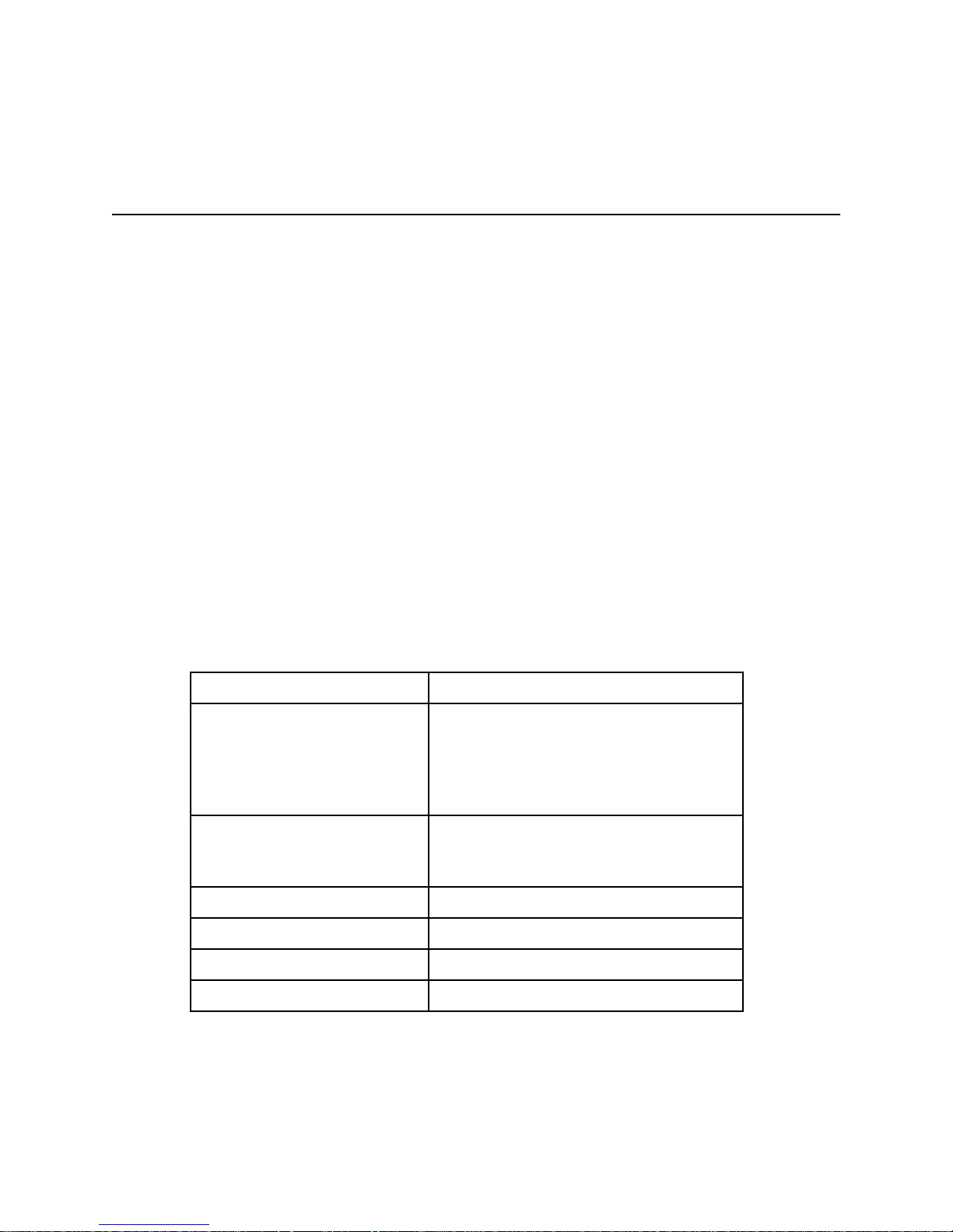
MODID Signal Termination
W3 configures the MODID signal termination for Slot 0/Non-Slot 0 operation. When configured
for Slot 0 operation (Figure 2-2a), W3 causes the MODID signal to be terminated with a 16.9 kΩ
pull-up resistor. When configured for Non-Slot 0 operation (Figure 2-2b), W3 causes the
MODID signal to be terminated with a 825 Ω pull-down resistor.
W7
J14J13
J15
W11
J16
W6
W1
W4
W5
W2
P2P1
W8
W3
J12
J17
W3 W3
a. Slot 0*
b. Non-Slot 0
* Factory Configuration
Figure 2-2. MODID Signal Termination Settings
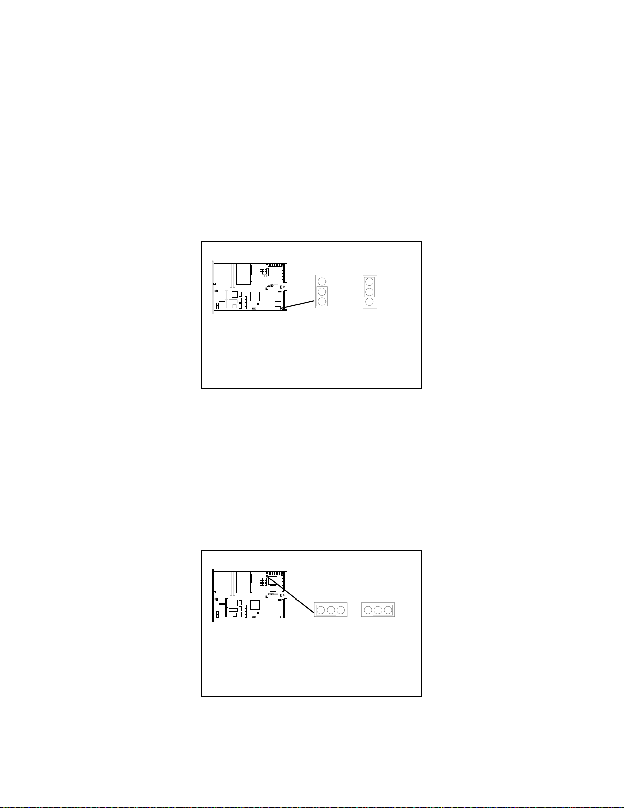
System Controller
W7 configures the System Controller for Slot 0/Non-Slot 0 operation. When configured for Slot
0 operation (Figure 2-3a), W7 enables the VXIpc-486 Model 200 Series System Controller
functions (SYSCLK and SYSRESET drivers, the Bus Arbiter and Bus Timer). When configured
for Non-Slot 0 operation (Figure 2-3b), W7 disables the System Controller functions.
W7
J14J13
J15
W11
J16
W6
W1
W4
W5
W2
P2P1
W8
W3
J12
J17
W7 W7
a. Slot 0*
b. Non-Slot 0
VXIpc-486 Model 200 Series for MS Windows 2-6 © National Instruments Corporation
* Factory Configuration
Figure 2-3. System Controller Settings
Page 23
Chapter 2 VXIpc-486 Configuration and Installation
CLK10 Generation
W6 configures the receiving source for the CLK10 reference. For internal clock generation, set
the jumper as shown in Figure 2-4a. When the source is from the CLK10 input on the front
panel of the VXIpc-486, set the jumper as shown in Figure 2-4b. Notice that when configured
for Non-Slot 0, CLK10 will always be received from the backplane.
W7
J14J13
J15
W11
J16
W6
W1
W4
W5
W2
P2P1
W8
W3
J12
J17
W6 W6
a. Slot 0*
b. Non-Slot 0
* Factory Configuration
Figure 2-4. CLK10 Generation Settings
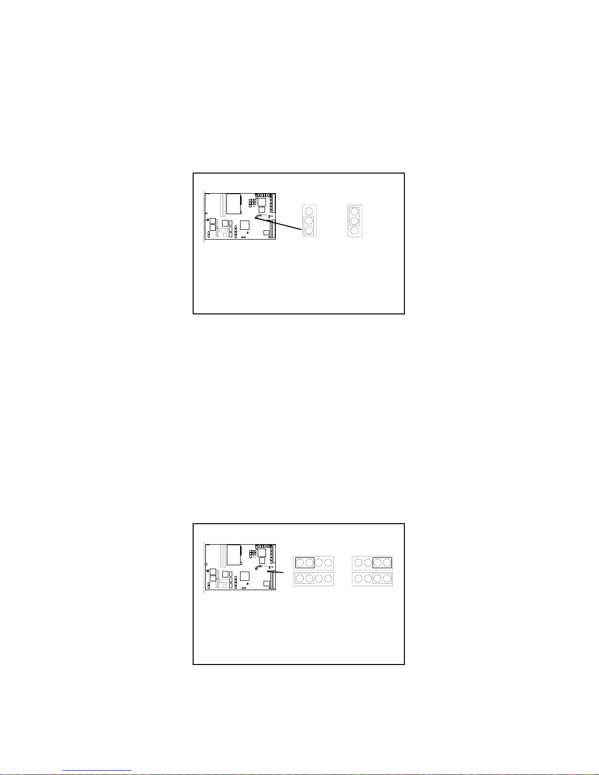
VXIbus CLK10
This jumper block configures the CLK10 transceivers. Figure 2-5(a) shows the default Slot 0
configuration in which the VXIpc-486 sources the CLK10 signal. If you want to configure the
VXIpc-486 as a Non-Slot 0 device, you should choose the setting in Figure 2-5(b). In this
configuration, the VXIpc-486 does not drive the CLK10 signal onto the bus.
Warning: Do not set the W1, W2, W4, W5 jumper block to any setting other than those
shown in Figure 2-5. Any other settings could result in damage to the VXIpc-486
and any other devices installed on the backplane.
W7
J14J13
J15
W4
W11
J16
W6
W1
W4
W5
W2
P2P1
W8
J12
J17
W5
W3
a. Slot 0,
Onboard
CLK10 Source*
W1
W2
W1
W4
W5
W2
b. Non-Slot 0
© National Instruments Corporation 2-7 VXIpc-486 Model 200 Series for MS Windows
* Factory Configuration
Figure 2-5. VXIbus CLK10 Settings
Page 24
VXIpc-486 Configuration and Installation Chapter 2
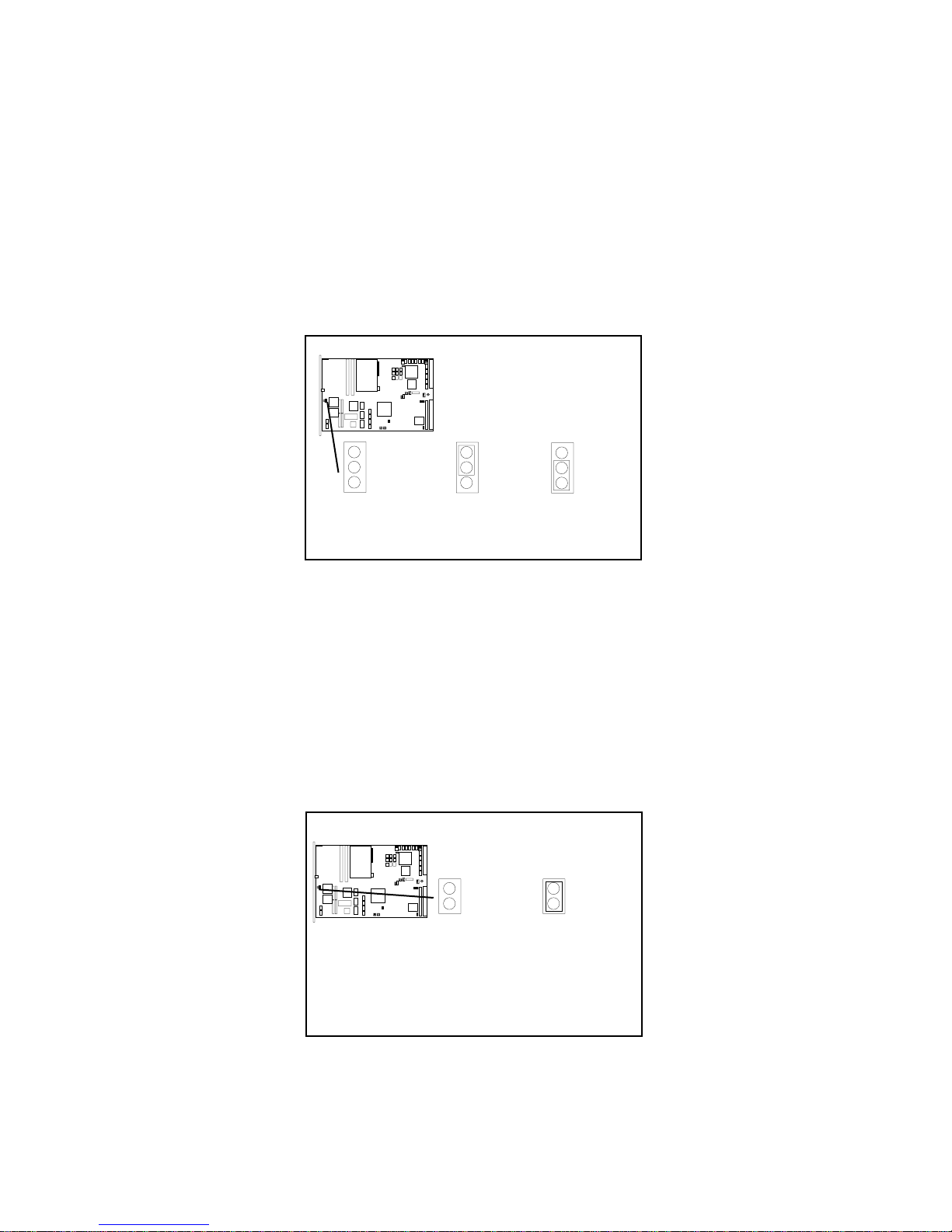
External CLK10
The W11 jumper configures the CLK SMB connector on the front panel. Keep the default
configuration shown in Figure 2-6(a) if the CLK connector is disconnected and used as neither
an input nor an output for the CLK10 signal. Figure 2-6(b) shows the configuration to use if you
want the CLK10 signal that appears on the backplane to also appear on the CLK SMB connector.
The configuration in Figure 2-6(c) is useful only if you have configured the W24 jumper to use
the external CLK10 input. In this setting, the signal supplied to the CLK SBM connector is
driven onto the VXIbus backplane as CLK10.
W7
J14J13
J15
W11
J16
W6
W1
W4
W5
W2
P2P1
W8
W3
J12
J17
W11 W11
a. Disabled*
* Factory Configuration
b. External
CLK10 Input
W11
c. External
CLK10 Output
Figure 2-6. External CLK10 Settings
External CLK10 Termination
The J16 jumper configures whether the CLK10 signal is terminated. This is important only if
you are daisy-chaining the CLK10 signal among multiple chassis. The source of the CLK10 and
the last chassis in the daisy-chain should be terminated to prevent electrical reflections. Notice
that this option is useful only if you have selected the external CLK by jumpers W11 and W6.
W7
J14J13
J15
W11
J16
W6
W1
W4
W5
W2
P2P1
W8
W3
J12
J17
J16 J16
a. External CLK10
Unterminated*
b. External CLK10
Terminated*
Figure 2-7. External CLK10 Termination Settings
VXIpc-486 Model 200 Series for MS Windows 2-8 © National Instruments Corporation
* Factory Configuration
Page 25
Chapter 2 VXIpc-486 Configuration and Installation
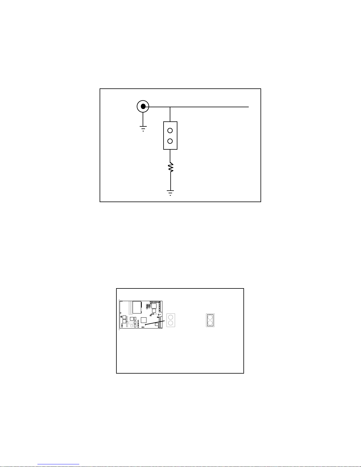
External Trigger Input Configuration
The external TTL trigger input interface is the SMB connector labeled TRG IN on the
VXIpc-486 front panel. Figure 2-8 shows the external trigger input circuit.
TRG IN
External Trigger Input Signal
Connector
W8
50Ω
Figure 2-8. External Trigger Input Circuit
The W8 jumper configures whether the external TTL trigger input is terminated with a 50 Ω
resistor to ground. This is important only if you are daisy-chaining the external trigger input
among multiple chassis. The source of the trigger input and the last chassis in the daisy-chain
should be terminated to prevent electrical reflections. Figure 2-9 shows the external trigger input
termination settings.
J16
Figure 2-9. External Trigger Input Termination Settings
© National Instruments Corporation 2-9 VXIpc-486 Model 200 Series for MS Windows
W7
J14J13
J15
W11
W6
W1
W4
W5
W2
P2P1
W8
W3
J12
J17
W8 W8
a. External
Trigger Input
Unterminated*
b. External
Trigger Input
Terminated
* Factory Configuration
Page 26
VXIpc-486 Configuration and Installation Chapter 2
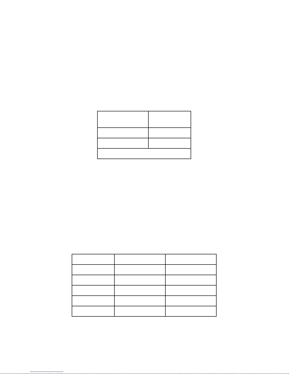
External Audio/Trigger Output Configuration
The external audio/trigger output interface is the SMB connector labeled AUDIO/TRG OUT on
the VXIpc-486 front panel.
You can configure the external audio/trigger output as either an audio output or a TTL trigger
output. The audio/trigger output is connected to the circuit card by a twisted-pair cable. You
can configure the audio/trigger output by connecting the cable to either J13 or J17. Table 2-3
shows the configuration options.
Table 2-3. External Audio/Trigger Output Configuration Options
External Audio/
Trigger Output Connected to
Trigger Out* J17
Audio Out J13
* Factory configuration
Installed System RAM Configuration
The amount of installed RAM is factory configured per customer order. You can change the
amount of installed RAM on VXIpc-486/1 models by installing dynamic RAM single in-line
memory modules (DRAM SIMMs) in positions A1 and A2, as shown in Table 2-4 and
Figure 2-1.
Warning: Do not attempt to change the factory RAM configuration of the VXIpc-486/2.
Disassembling the internal brackets in an attempt to expose the DRAM SIMM
sockets will void your warranty.
Table 2-4. Installed RAM Configuration Options
Installed RAM A2 A1
2 MB 1 MB x 18 Not Installed
4 MB 1 MB x 18 1 MB x 18
8 MB 4 MB x 18 Not Installed
10 MB 4 MB x 18 1 MB x 18
16 MB 4 MB x 18 4 MB x 18
VXIpc-486 Model 200 Series for MS Windows 2-10 © National Instruments Corporation
Page 27

Chapter 2 VXIpc-486 Configuration and Installation
National Instruments recommends the following DRAM SIMMs for use with the VXIpc-486/1:
• Toshiba part number THM181000ASG-10L or equivalent 1 MB x 18 SIMMs
• Toshiba part number THM184080SG-10L or equivalent 4 MB x 18 SIMMs.
Note: Always reconfigure the VXIpc-486/1 to the factory DRAM configuration shown on
the ID label before returning it to the factory for repairs or upgrades.
80387SX Math Coprocessor Configuration
An 80387SX math coprocessor is installed in your VXIpc-486 Model 200 Series at the factory, if
ordered as an option.
Warning: Do not attempt to install or remove a math coprocessor in the VXIpc-486/2.
Disassembling the internal brackets in an attempt to expose the 80387SX socket
will void your warranty.
You can install an Intel 387SX or equivalent math coprocessor in a VXIpc-486/1 yourself, by
following these steps:
1. Place the 80387SX (in its shipping package) on the anti-static mat with the VXIpc-486.
2. Locate the 80387SX socket (U65) on the VXIpc-486 (See Figure 2-1).
Warning: Be sure to orient the 80387SX correctly before inserting it in the socket. If you
insert the chip the wrong way, the 80387SX and the VXIpc-486/1 will be
damaged.
3. Orient the 80387SX so that the corner notch on the 80387SX matches the position of the
corner notch in Figure 2-1 and the reference dot (locating pin 1) matches the socket
reference.
Warning: Avoid excessive pressure while inserting the 80387SX. Bending the circuit card
could damage the VXIpc-486.
4. Insert the 80387SX into the socket, pressing firmly and evenly to fully seat the pins.
Note: Always reconfigure the VXIpc-486/1 to the factory math coprocessor configuration
shown on the ID label before returning it to the factory for repairs or upgrades.
If you have finished configuring the VXIpc-486, you are now ready to install it in your
mainframe.
© National Instruments Corporation 2-11 VXIpc-486 Model 200 Series for MS Windows
Page 28

VXIpc-486 Configuration and Installation Chapter 2
Installing and Starting Up the VXIpc-486
The following installation instructions apply to the VXIpc-486 Model 200 Series. Refer to your
mainframe user manual for further instructions regarding mainframe configuration and module
installation. Figure 2-10 shows the location of the VXIpc-486 front panel connectors. Refer to
Appendix C, Connectors, for pinout details about each connector.
1. Turn off the mainframe power.
Warning: Installing a VXIpc-486 Model 200 Series configured for Slot 0 operation into
any slot other than Slot 0 can result in damage to the VXIpc-486, the backplane,
and the Slot 0 device.
2. If the VXIpc-486 is configured for Slot 0 operation, install it in Slot 0. If the VXIpc-486
is configured as a Non-Slot 0 device, install it in any slot other than Slot 0. The VXIbus
Slot and External CLK10 Configuration Options section, earlier in this chapter, describes
the different configuration options for Slot 0 and non-Slot 0 applications. Refer also to
your mainframe user manual for instructions regarding slot configuration.
3. Tighten the retaining screws at the top and bottom of the front panel.
4. Connect the keyboard to the KEYBOARD connector. Use the keyboard adapter cable
that you received with your kit to adapt AT-style keyboards to the VXIpc-486 mini-DIN
connector.
5. Connect the VGA monitor video cable to the VGA connector and tighten the screws.
6. On VXIpc-486 models without an internal floppy drive, connect the optional external
floppy drive (EFD) to the DISK DRIVE connector. The EFD is not compatible with
models that have an internal floppy drive.
7. Connect serial devices to the COM1 or COM2 connectors, if required by your system
configuration. Use the COM2 adapter cable (available as an accessory) to attach serial
devices to COM2.
8. Connect parallel devices to the LPT connector, if required by your system configuration.
9. Connect the external CLK10 signal to the CLK connector, if required by your system
configuration.
10. Connect the external trigger input signal to the TRG IN connector, if required by your
system configuration.
11. Connect the external audio or trigger output signal to the AUDIO/TRG OUT connector, if
required by your system configuration.
VXIpc-486 Model 200 Series for MS Windows 2-12 © National Instruments Corporation
Page 29

Chapter 2 VXIpc-486 Configuration and Installation
12. To start up the VXIpc-486, turn on the mainframe power. Also apply power to any
peripherals, such as the monitor. The basic input/output system (BIOS) boot sequence
should now begin to display startup messages on the monitor. Chapter 3, BIOS Setup,
contains information on BIOS that you may need in case you either have special BIOS
configuration requirements or you encounter a BIOS-related error message.
The front panel LED indicators also provide information about the VXIpc-486 and VXIbus
system status. The SYSFAIL and FAILED LEDs remain lit until the VXIpc-486 initialization
program VXIINIT.EXE is run. See Appendix B, NI-VXI Software Overview, for more
information about VXIINIT. See Appendix C, Front Panel Indicators, for more information
about the front panel LED operation.
Figure 2-10. VXIpc-486 Model 200 Series Front Panel
© National Instruments Corporation 2-13 VXIpc-486 Model 200 Series for MS Windows
Page 30

Chapter 3
BIOS Setup
This chapter describes how to set up the basic input/output system (BIOS) for the VXIpc-486
Model 200 Series computer. The VXIpc-486 uses the Quadtel AT Compatible Enhanced BIOS.
The BIOS defines the way in which software interacts with the VXIpc-486 hardware. The BIOS
has a number of setup parameters that contain the VXIpc-486 system configuration information.
The BIOS setup parameters are stored in the CMOS RAM, which is backed up by battery. You
use the BIOS utility Setup (part of the Quadtel Extended BIOS Software System) to modify the
time-of-day, date, floppy and hard disk types, processor speed, and shadow RAM operation.
The BIOS parameters are factory configured for proper operation. Unless you have special
BIOS configuration requirements, you can proceed to Chapter 4, NI-VXI Software Installation
and Configuration.
Running Setup
Occasionally, you may encounter a BIOS-related error message that requires you to run Setup.
You may also need to change one or more of the BIOS parameters for compatibility with a
software application. If you need to run Setup, follow these steps:
1. Press <F2> after power-on to display the Extended BIOS Software main window. This
window also appears if you press <F2> after a power-on self-test error is displayed.
2. Select Setup, using the Up/Down Arrow and <Enter> keys, to display the Extended BIOS
Setup window.
3. Use the Up/Down Arrow or <Tab> keys to select the item you want to change. Press <F5>
to select the previous (smaller) value, <F6> to select the next (larger) value, or <F9> to
automatically configure the selected item.
4. Press <F10> to save the configuration parameters you edited.
5. Press <Esc> to exit Setup. If you have not saved your changes, you can do so at this time.
6. Press <Esc> to exit the Extended BIOS Software main window. The VXIpc-486 will restart.
© National Instruments Corporation 3-1 VXIpc-486 Model 200 Series for MS Windows
Page 31

BIOS Setup Chapter 3
Table 3-1 shows the default BIOS configuration parameters.
Table 3-1. Default BIOS Setup Configuration Parameters
Parameter Configuration
System Memory Press <F9> to Auto Configure
Extended Memory Press <F9> to Auto Configure
EMS Memory Press <F9> to Auto Configure
Power-up Speed Fast
BIOS Shadow System in RAM
Video in RAM
Disk Drive 0
Internal Floppy Disk or EFD
No Floppy Disk Drive
1.44 MB 3.5 in.
Not installed
Disk Drive 1 Not installed
Fixed Disk 0 Type As shown on the ID label <AUTO>
Fixed Disk 1 Type None
VXIpc-486 Model 200 Series for MS Windows 3-2 © National Instruments Corporation
Page 32

Chapter 4
NI-VXI Software Installation and
Configuration
This chapter contains instructions for installing and configuring the NI-VXI software for the
VXIpc-486 Model 200 Series computer. Your VXIpc-486 is shipped from the factory with
MS-DOS, Windows, NI-VXI, and NI-488.2 software already installed on the hard disk. The
information on installing the NI-VXI software is included in this chapter should you ever need to
reinstall it. For instructions on installing MS-DOS and Windows, refer to the documentation
included in your Microsoft DOS and Windows kit. Because the VXIpc-486 built-in GPIB port is
compatible with the industry-standard AT-GPIB plug-in GPIB interface board for PC AT
computers, please refer to Getting Started with Your AT-GPIB and the NI-488.2 Software for
MS-DOS and to Using Your NI-488.2 Software with Microsoft Windows for information about
using the capabilities of the AT-GPIB and the NI-488.2 software in your system.
For a list of all the files and program, refer to Appendix B, NI-VXI Software Overview. If you
encounter problems using the NI-VXI software, consult Appendix H, Common Questions, and
Appendix I, Troubleshooting.
Installing the Software
The VXIpc-486 is shipped with Microsoft Windows and the NI-VXI software installed on the
hard disk. Unless you need to reinstall part or all of the NI-VXI files, skip this section and
continue with Configuring the NI-VXI Software, later in this chapter.
The NI-VXI distribution disks that came with your VXIpc-486 contain the NI-VXI files as well
as an INSTALL program. The INSTALL program is used to install a software update or to
reinstall software in the event that your files were accidentally erased. Follow these steps to
reinstall all or part of the NI-VXI software.
1. The NI-VXI software requires approximately 3 MB of free space on your hard disk. Create
the necessary free space on the hard disk before starting the installation.
2. Run INSTALL.EXE on distribution disk 1. You can run this program from the Windows
Program Manager's File menu, Run option, or from the DOS prompt (which loads Windows
and then runs INSTALL). However, it cannot be run from the Windows DOS Shell.
INSTALL is a graphical, interactive, self-guiding program, which will install all the
necessary files (for a complete or partial installation, as user-specified) on the hard disk. In
addition, it will optionally modify the AUTOEXEC.BAT, PROGMAN.INI, SYSTEM.INI, and
WIN.INI initialization files accordingly. The program prompts you to enter the following
information:
© National Instruments Corporation 4-1 VXIpc-486 Model 200 Series for MS Windows
Page 33

NI-VXI Software Installation and Configuration Chapter 4
• Environments to install: You can choose whether to install NI-VXI for DOS, Windows,
or both. The default is to install both.
• Languages to install: You can choose whether to install the Microsoft C, Borland C,
and/or QuickBASIC libraries. The default is to install all of them, but if you are using
only one compiler, you can select only that compiler.
• Destination directory: This is the complete pathname of the directory where you want to
install the software.
• Modifying DOS initialization files: You can choose whether INSTALL modifies the
AUTOEXEC.BAT file to reflect the location of the NI-VXI library. If you choose to let
INSTALL do this, you must also enter the drive where AUTOEXEC.BAT can be found.
• Modifying Windows initialization files: You can choose whether INSTALL modifies the
PROGMAN.INI, SYSTEM.INI, and WIN.INI files to reflect the location of the NI-VXI
library. If you choose to let INSTALL do this, you must also enter the directory in which
the Windows files can be found.
You can quit the INSTALL program at any time by choosing Exit from the initial screen,
or by pressing the Cancel button once installation has begun. If you do not have a mouse,
pressing the <Esc> key performs the same action. In either case, INSTALL prompts you to
be certain you really want to quit at that time. If you choose to run the INSTALL program
again, it starts over and recopies all the necessary files. Of course, if you made any changes
from the default configuration, you will need to specify those changes once again.
As mentioned previously, INSTALL optionally modifies the AUTOEXEC.BAT,
PROGMAN.INI, SYSTEM.INI, and WIN.INI files. For each file that you
do modify,
it changes the old file's extension to .BAK and keeps it for safety purposes. For each file
that you do not modify, it creates a file in the NI-VXI directory with the changes it proposes
you make to the files. The files that it creates in this situation have the same filename but
with the extension .VXI. For example, if you choose not to let INSTALL modify
AUTOEXEC.BAT, it will create a file in the NI-VXI directory called AUTOEXEC.VXI,
with changes you will need to make to AUTOEXEC.BAT.
Modifying the AUTOEXEC.BAT File
If you choose to let INSTALL modify your AUTOEXEC.BAT file, it updates the setting of
environment variables PATH, LIB, and INCLUDE to include the relevant subdirectories of the
NI-VXI directory. The previously specified directories in PATH, LIB, and INCLUDE remain
unchanged. INSTALL also adds a new environment variable NIVXIPATH, and appends a
command line to execute VXIINIT.EXE automatically.
If you choose not to let INSTALL modify your AUTOEXEC.BAT file, refer to the
AUTOEXEC.VXI file in your NI-VXI directory for suggestions on how to change the
following lines manually.
VXIpc-486 Model 200 Series for MS Windows 4-2 © National Instruments Corporation
Page 34

Chapter 4 NI-VXI Software Installation and Configuration
• The PATH variable should include the full path to the subdirectory where the NI-VXI utilities
and NIVXI.DLL are located, in addition to whatever other directories you have already
specified in PATH. The path must be specified so that Windows can locate the executable
code when the library needs to be loaded. Normally, these files reside in the root of the
NI-VXI directory, and also the WIN subdirectory.
• The LIB variable should include the full path to the subdirectories that contain the C libraries
for the compiler you choose to install.
• The INCLUDE variable should include the full path to the subdirectory that contains the
NI-VXI include files. By default, the include files reside in the INCLUDE subdirectory of
the NI-VXI directory.
• The NIVXIPATH variable should contain the full path to the NI-VXI directory.
Modifying the PROGMAN.INI File
If you choose to let INSTALL modify your PROGMAN.INI file, it specifies the NIVXI.GRP
folder file as shown below.
[Settings]
Order=
x
<etc>
[Groups]
Group
x
= <
NI-VXI directory
>\WIN\NIVXI.GRP
where <etc> represents the numbers already on this line, and where x is a new number between
1 and 99 and is the same on both of the preceding lines.
Modifying the SYSTEM.INI File
If you choose to let INSTALL modify your SYSTEM.INI file, it adds a line to the [386Enh]
section to load a device driver that NI-VXI needs for shared memory accesses. The file, which
must be loaded at Windows startup, is called NIVXIPHM.386 and is normally located in the
WIN subdirectory of the NI-VXI directory as shown below. INSTALL also adds a line that
keeps Windows from using the VXI space for its own purposes. In addition, a new section
[NIVXI] is created, which NIVXIPHM.386 uses during Windows system startup.
[386Enh]
DEVICE=
EMMexclude=
<NI-VXI directory>
A000-EFFF
\WIN\NIVXIPHM.386
[NIVXI]
NIVXIPATH=
<NI-VXI directory>
LoadData=6Bytes
If you choose not to let INSTALL modify your SYSTEM.INI file, refer to the SYSTEM.VXI file
in your NI-VXI directory for suggestions on how to make the necessary changes yourself.
© National Instruments Corporation 4-3 VXIpc-486 Model 200 Series for MS Windows
Page 35

NI-VXI Software Installation and Configuration Chapter 4
Modifying the WIN.INI File
If you choose to let INSTALL modify your WIN.INI file, it adds the following lines to the
WIN.INI file:
[NIVXI]
NIVXIPATH=
In this situation, the NIVXIPATH variable is used by the NIVXI.DLL dynamic link library in
addition to the application programs that come with NI-VXI (for example, RESMAN.EXE) to
locate the NI-VXI configuration and help files.
If you choose not to let INSTALL modify your WIN.INI file, refer to the WIN.VXI file in your
NI-VXI directory for suggestions on how to make the necessary changes yourself.
<NI-VXI directory>
Notes: The NIVXIPATH variables in the SYSTEM.INI, WIN.INI, and
AUTOEXEC.BAT
files should point to the same subdirectory.
After you execute INSTALL, you should exit and reenter Windows before running
any of the NI-VXI software. In fact, once you have exited Windows, it is advisable
to reboot your machine (or at least run AUTOEXEC.BAT) to make your system aware
of the NI-VXI directory.
Once the NI-VXI package is installed, run VXIINIT.EXE and then RESMAN.EXE.
Configuring the NI-VXI Software
Run VXIINIT from DOS or the Windows DOS shell to initialize and display the VXIpc-486
configuration settings. The default configuration is Slot 0 System Controller, Resource
Manager, Message-Based device. To change the current settings, or to view the configuration
options, run VXIEDIT or VXITEDIT and select the Configuration Editor from the Main
menu.
You can use VXIEDIT or
device that is installed in the system. You can easily modify the configuration tables required
for VXIbus and MXIbus operation. You can also configure interrupts, triggers, and the utility
bus for single- or multiple-mainframe system configurations. The VXIEDIT program, which
you can access from DOS or the Windows DOS shell, uses a series of interactive graphical
screens to display information for the various editors. You can use the text-based VXITEDIT
program within Windows to accomplish the same tasks by entering commands at the keyboard.
VXITEDIT to edit the description of the VXIpc-486 or any other
For more details on how to use VXIEDIT, refer to the NI-VXI DOS Utilities Reference Manual.
For more details on how to use VXITEDIT, refer to the NI-VXI Text Utilities Reference Manual.
VXIpc-486 Model 200 Series for MS Windows 4-4 © National Instruments Corporation
Page 36

Chapter 4 NI-VXI Software Installation and Configuration
Running VXIEDIT from DOS or the Windows DOS Shell
VXIEDIT.EXE is the VXI resource editor program that runs in DOS or the Windows DOS shell.
You can use this program to configure the system and to edit the manufacturer name and ID
numbers, the model names of VXI and non-VXI devices in the system, and the system interrupt
configuration information. This program also displays the system configuration information
generated by the Resource Manager.
To run VXIEDIT from any directory, make sure that both the PATH and NIVXIPATH
environment variables have the destination directory of the NI-VXI software added to it. PATH
is used to find the application itself, while NIVXIPATH is used by the application to find the
different configuration files (*.CFG), table files (*.TBL), and help files (*.HLP) during its
execution. The default pathname used by the program if NIVXIPATH is not set is C:\NIVXI.
Figure 4-1 shows the functions available under VXIEDIT.
Figure 4-1. VXIEDIT Main Menu (from DOS)
When you select the Configuration Editor from the Main menu, the Logical Address
Configuration Editor menu (shown in Figure 4-2) is displayed. The following sections describe
the various configuration options available under the Logical Address Configuration, Bus
Configuration, and Device Configuration Editor menus.
Select Next and Previous to move between the three configuration editors. You can change the
default settings to any value within the range shown to the right of each item by using the left
and right arrow keys.
© National Instruments Corporation 4-5 VXIpc-486 Model 200 Series for MS Windows
Page 37

NI-VXI Software Installation and Configuration Chapter 4
You can save your changes by selecting Save. Saving the changes updates files VXILA.CFG,
VXIBUS.CFG, and VXIDEV.CFG. VXIINIT.EXE uses these files to update the soft-configured
settings, including board interrupts, shared RAM size, VXI register contents, and bus interface.
You can exit the program at any time without saving any changes you have made by selecting
Abort.
Logical Address Configuration
The following paragraphs describe options available under the Logical Address Configuration
Editor. Figure 4-2 shows the Logical Address Configuration Editor (VXIla) menu.
Figure 4-2. VXIpc-486 Logical Address Configuration Editor (from DOS)
Logical Address
The logical address is an 8-bit number that uniquely identifies the VXIpc-486. It can be
configured as a static device with a logical address range from 0 through 254. Logical address
255 configures the VXIpc-486 as a dynamic device, as specified in the VXIbus System
Specification. The default logical address is 0. If you do not want the VXIpc-486 to be the
system Resource Manager, change this value to an unused logical address other than 0.
Device Type
This field indicates the classification of the VXIbus device. The options are Extended Device
(EXT), Message-Based Device (MBD), and Register-Based Device (RBD). The default is MBD.
The VXIpc-486 Device Type affects only the contents of the Device Class field in the Device
Type register. The functionality of the other registers does not change.
VXIpc-486 Model 200 Series for MS Windows 4-6 © National Instruments Corporation
Page 38

Chapter 4 NI-VXI Software Installation and Configuration
Address Space
This field indicates the addressing mode(s) of the device's operational registers. The VXIpc-486
can be configured as an A16 only, A16/A24, or A16/A32 device. The default is A16 only.
VXI Shared RAM (Byte Order)
The local RAM of the VXIpc-486 Model 200 Series computer can be slave-accessed in either
A24 or A32 space in D08 and D16 data transfer modes. This field, which indicates the primary
and secondary byte swapping schemes for slave accesses to the local RAM space, can be set to
either Intel (INT, Little Endian) or Motorola (MOT, Big Endian). The default primary byte
ordering is Intel for backward compatibility reasons. When the addressing mode is A16 only,
this field is ignored.
VXI Shared RAM (MBytes)
This field indicates the number of megabytes of local RAM that are shared in either A24 or A32
space. The VXIpc-486 can be set up to have either one or two windows into the local RAM.
When set up with one window, all slave accesses through this window use the primary byte order
scheme. When there are two windows, accesses through the first (lower) window see the local
RAM using the primary byte order scheme, and accesses through the second (upper) window see
the same local RAM but use the secondary byte order scheme. In Table 4-1, primary and
secondary byte order refer to the setting of the previous field. When the addressing mode is A16
only, this field should be set to DISABLED.
Table 4-1. VXI Shared RAM Options
Address Space Options Description
A16 DISABLED VXI Shared RAM disabled
A16/A24 4, 0
Four megabytes of local RAM are shared in
A24 space. Slave accesses to this RAM are in
the primary byte order.
4, 4
In this option, 4 MB of local RAM are shared,
but 8 MB are requested in A24 space. Accesses
to the lower 4 MB are in the primary byte order.
Accesses to the upper 4 MB see the same local
RAM in the secondary byte order.
8, 0
Eight megabytes of local RAM are shared in
A24 space. Slave accesses to this RAM are in
the primary byte order.
(continues)
© National Instruments Corporation 4-7 VXIpc-486 Model 200 Series for MS Windows
Page 39

NI-VXI Software Installation and Configuration Chapter 4
Table 4-1. VXI Shared RAM Options (Continued)
Address Space Options Description
A16/A32 4, 0
4, 4
8, 0
8, 8
ALL, 0
Four megabytes of local RAM are shared in
A32 space. Slave accesses to this RAM are in
the primary byte order.
In this option, 4 MB of local RAM are shared,
but 8 MB are requested in A32 space. Accesses
to the lower 4 MB are in the primary byte order.
Accesses to the upper 4 MB see the same local
RAM in the secondary byte order.
Eight megabytes of local RAM are shared in
A32 space. Slave accesses to this RAM are in
the primary byte order.
In this option, 8 MB of local RAM are shared,
but 16 MB are requested in A32 space.
Accesses to the lower 8 MB are in the primary
byte order. Accesses to the upper 8 MB see the
same local RAM in the secondary byte order.
Sixteen megabytes of local RAM are shared in
A32 space. Slave accesses to this RAM are in
the primary byte order.
Shared Memory Pool (Windows)
This field indicates the size of memory in kilobytes that is allocated on Windows startup to be
used exclusively by VXImemAlloc function calls from both DOS and Windows applications.
The allowable range is from 0 to 65535 KB. The default value is 0 KB.
Slave Block Transfer Mode
The VXIpc-486 does not currently support block transfers in either slave or master mode
accesses. This field is statically configured to NO, and cannot be changed.
Slave Supervisory Access Only
When YES is selected, the VXIpc-486 will acknowledge only supervisory accesses.
Nonprivileged accesses will result in a bus error. This is true for all A16, A24, and A32 slave
accesses. When NO is selected, the VXIpc-486 will acknowledge both supervisory and
nonprivileged accesses. The default option is NO.
VXIpc-486 Model 200 Series for MS Windows 4-8 © National Instruments Corporation
Page 40

Chapter 4 NI-VXI Software Installation and Configuration
Resource Manager Delay
This field specifies the time in seconds that the Resource Manager (RM) waits before accessing
any other VXIbus device's A16 configuration registers. The allowable range is from 0 to 65535
seconds. The default value is 5 seconds.
Bus Configuration
The following paragraphs describe options available under the Bus Configuration Editor.
Figure 4-3 shows the VXIbus Configuration Editor (VXIbus) menu.
Figure 4-3. VXIpc-486 Bus Configuration Editor (from DOS)
Bus Request Level
This field sets the VXIbus request level (BR0-3) for the VXIpc-486. The default value is level 3.
Fair Requester Timeout
You can configure the VXIpc-486 as a fair requester (Request On No Request, or RONR) with a
timeout period of either infinity or within the range of 2 to 28 µs (increments of 2 µs), or you can
configure it as an unfair requester by selecting the field value of DISABLE. The default value is
∞ (INF), specifying an infinite timeout period.
© National Instruments Corporation 4-9 VXIpc-486 Model 200 Series for MS Windows
Page 41

NI-VXI Software Installation and Configuration Chapter 4
Bus Release Mechanism
This field sets the VXIbus release mechanism, which can be Release On Request (ROR) or
Release When Done (RWD). The default value is ROR.
Bus Arbitration
The field sets the VXIbus arbitration mode. The two options are Priority (PRI) or Round Robin
Select (RRS). The default value is PRI. The bus arbitration mode is relevant only when the
VXIpc-486 is the Slot 0 device.
Local Bus Timeout
This field sets the timeout period for the VXIpc-486 local bus. You can set the timeout within
the range from 4 to 512 µs, in powers of 2 (4, 8, 16, 32, 64, 128, 256, and 512), or you can
disable this function. The default value is 32 µs. When the VXIpc-486 is not the System
Controller, you should select DISABLE. In such a case, you should have configured the
VXIpc-486 as a Non-Slot 0 device as described in Chapter 2.
VXIbus Timeout
This field sets the timeout period for the VXIbus bus timeout (BTO) unit. When the VXIpc-486
is the System Controller, you can set the BTO period within the range from 4 to 512 µs in powers
of 2 (4, 8, 16, 32, 64, 128, 256, and 512). The default value is 128 µs. When the VXIpc-486 is
not the System Controller, you should select DISABLE. In such a case, you should have
configured the VXIpc-486 as a Non-Slot 0 device as described in Chapter 2.
Bus Acquisition Time in Timeout
This field determines whether the arbitration time to acquire the VXIbus is included in the local
bus timeout. In embedded-only systems, the default is to include bus acquisition time. In MXI
systems, however, the arbitration time may be excessively long. In such a case, it may be
preferable to exclude the bus acquisition time from the overall timeout.
VXIpc-486 Model 200 Series for MS Windows 4-10 © National Instruments Corporation
Page 42

Chapter 4 NI-VXI Software Installation and Configuration
Device Configuration
The following paragraphs describe options available under the Device Configuration Editor.
Figure 4-4 shows the Device Configuration Editor (VXIdev) menu.
Figure 4-4. VXIpc-486 Device Configuration Editor (from DOS)
SYSRESET Resets PC
When YES is selected, a SYSRESET on the backplane causes the VXIpc-486 to reboot. When
NO is selected, a SYSRESET on the backplane does not reboot the VXIpc-486. The default
value for this field is NO.
Use System Sanity Timer
When YES is selected, if a misbehaved NI-VXI application causes the system to hang, the
VXIpc-486 asserts the SYSFAIL* signal on the backplane. When NO is selected, if the system
hangs, the VXIpc-486 does not assert SYSFAIL*. In general, the sanity timer is useful by
alerting you that your application has gone awry. However, you should turn off the sanity timer
when debugging an NI-VXI application because some debuggers conflict with the sanity timer
mechanism. The default value for this field is YES.
Servant Area Size
This field designates the Servant Area size, which is supplied to the Resource Manager in
response to the Read Servant Area command (if the VXIpc-486 is not the Resource Manager
in your system). The Servant Area size is an 8-bit value (0 through 255) that indicates the
VXIpc-486 Servant area. The Servant area begins at the logical address following the
VXIpc-486 logical address, and includes N contiguous logical addresses, where N is the value
© National Instruments Corporation 4-11 VXIpc-486 Model 200 Series for MS Windows
Page 43

NI-VXI Software Installation and Configuration Chapter 4
of the Servant Area size. This field is meaningful only when the VXIpc-486 is configured as
a Message-Based device. You can set the Servant Area size within the range 0 to 255. The
default value is 0.
Note: If the VXIpc-486 is the Resource Manager, this setting is irrelevant.
Protocol Register
This field specifies the contents of the Protocol register, indicating which protocols the device
supports. This field is meaningful only when the VXIpc-486 is configured as a Message-Based
device. The default value is 0x0FF0 (Commander, Signal Register, Master).
Read Protocol Response
This field specifies the response value to a Read Protocol command received by the VXIpc-486
from the Resource Manager (if the VXIpc-486 is not the Resource Manager in your system).
This field is meaningful only when the VXIpc-486 is configured as a Message-Based device.
The default value is 0x8448 (Response Generation, Event Generation, Programmable Handler,
Word Serial Trigger, Instrument, Extended Longword Serial, Longword Serial).
Number of Handlers
This field gives the number of interrupt handlers that the VXIpc-486 supports, which can range
from 0 to 7. The default value is 1.
Number of Interrupters
This field gives the number of interrupters that the VXIpc-486 supports, which can range from
0 to 7. The default value is 0.
Exiting VXIEDIT from DOS and Reinitializing the Hardware
Select Exit or press the <Esc> key to quit the VXIEDIT program. If you changed any of the
software configuration information, VXIEDIT prompts you to save your changes before exiting
the configuration menu. Saving the configuration information updates the configuration files
VXILA.CFG, VXIBUS.CFG, and VXIDEV.CFG. Run VXIINIT.EXE to reinitialize the hardware
according to the new settings.
If you changed any of the software configuration settings from the default, record the new
settings on the VXIpc-486 Model 200 Series Hardware and Software Configuration Form
in Appendix J.
VXIpc-486 Model 200 Series for MS Windows 4-12 © National Instruments Corporation
Page 44

Chapter 4 NI-VXI Software Installation and Configuration
Running VXITEDIT from Windows
As an alternative to VXIEDIT you can use VXITEDIT, a text-based VXI resource editor that
runs in the Windows environment. It uses the NIVXIPATH variable set in the WIN.INI file to
locate the configuration files, table files, and help files. When NIVXIPATH is not specified in
WIN.INI, it assumes the default directory C:\NIVXI.
To run VXITEDIT, select the File menu, Run command from the Windows Program Manager
and type VXITEDIT.EXE. Refer to the
NI-VXI Text Utilities Reference Manual for further
information on how to use VXITEDIT.
Exiting VXITEDIT from Windows and Reinitializing the Hardware
To exit VXITEDIT, type exit or the number 11 when the main menu is displayed. If you
changed any information, you are prompted to save your changes before exiting the menu.
Saving the configuration information updates the configuration files VXILA.CFG,
VXIBUS.CFG, and VXIDEV.CFG. Run VXIINIT.EXE to reinitialize the hardware
according to the new settings.
If you changed any of the software configuration settings from the default, record the new
settings on the VXIpc-486 Model 200 Series Hardware and Software Configuration Form
in Appendix J.
© National Instruments Corporation 4-13 VXIpc-486 Model 200 Series for MS Windows
Page 45

Chapter 5
Using NI-VXI with Microsoft Windows
This chapter discusses programming information for you to consider when developing
applications that use the NI-VXI driver.
After you have verified that the driver software has been installed successfully, you can begin to
develop your VXI application software. Be sure to check the README.DOC file for the latest
application development notes. Remember that you must run the VXIINIT initialization
program before performing any VXI operations and after each computer reset. You must also
run RESMAN each time the chassis power is cycled.
The NI-VXI Software Reference Manual for C contains an overview of NI-VXI functionality in
Chapter 2, Introduction to the NI-VXI Functions. Chapters 3 through 13 contain overviews and
detailed descriptions of the NI-VXI functions.
Interactive Control of NI-VXI
The easiest way to learn how to communicate with your instruments is by controlling them
interactively. Use the VXI interactive control program (VIC from DOS or
Windows) to write to and read from your instruments. This program helps you learn how to
communicate with devices, troubleshoot problems, and develop your application. Both programs
display the status of your VXI transactions and inform you of any errors that occur.
VICTEXT from
The VIC or VICTEXT command set includes most of the capability of NI-VXI function calls in
addition to unique auxiliary commands. You can use this utility to send data and Word Serial
commands to devices and to display data received from devices on the screen. After each
function executes, the program displays the device's response and the status.
The VIC and VICTEXT utilities are designed to help you learn how to use the NI-VXI functions
to program devices. Once you develop a sequence of steps that works successfully for your
system, you can easily incorporate the sequence into an application program using the
appropriate language and syntax.
Caution: If
NIVXI.DLL
program that uses the NI-VXI library in a DOS shell. Conflict occurs if both the
DOS and Windows NI-VXI drivers are active at the same time, and may cause a
system failure. To guard against this conflict, the safest approach is to always
exit Windows before attempting to execute any DOS program that uses the
NI-VXI Library, including
shell, however, if you ensure that no other Windows application that uses the
NIVXI.DLL
is loaded in memory, do not attempt to execute
VIC
. You can execute
file is executing.
VIC
VIC
or any DOS
from a Windows DOS
© National Instruments Corporation 5-1 VXIpc-486 Model 200 Series for MS Windows
Page 46

Using NI-VXI with Microsoft Windows Chapter 5
Refer to the NI-VXI DOS Utilities Reference Manual on how to use VIC from DOS and to learn
about its features, and to the NI-VXI Text Utilities Reference Manual on how to use VICTEXT
from Windows and to learn about its features.
Example Programs
The EXAMPLES subdirectories contain various example programs along with makefiles that
show how to use various functions in the NI-VXI software and how to develop application
programs using these functions. Make certain that the environment variables LIB and
INCLUDE are set correctly as described in the Installing the Software section in Chapter 4. Also
refer to the NI-VXI Software Reference Manual for C for additional examples.
Note: When compiling NI-VXI applications, you must define the macro
are developing a Windows application) or the macro
a DOS application) in your makefile/project. Refer to the example programs for
more details.
VXIDOS
VXIWIN
(if you are developing
(if you
Memory Model
The NI-VXI libraries were compiled using the large memory model. All DOS applications must
also be compiled for the large memory model. However, Windows application programs that
link with the NI-VXI library can also use the medium, compact, or small memory models.
Because of this ability to use different memory models for your application, you can not only
take advantage of the efficiency inherent in small memory model programs, but also run multiple
instances of the application as well. (Normally, you cannot run multiple instances of an
application if it is a large memory model application.)
Multiple Applications Using the NI-VXI Library
Multi-application support is another feature in the NI-VXI library. You can have several
applications that use the NI-VXI library running simultaneously. In addition, you can have
multiple instances of the same application that uses the NI-VXI library running simultaneously.
The NI-VXI functions perform in the same manner whether you have only one application that
uses the NI-VXI library or several applications (or several instances of an application) all trying
to use the NI-VXI library. Because the NI-VXI functions execute to their completion without
yielding control of the microprocessor, function calls from different applications do not
inadvertently conflict with one another.
However, you do need to be careful in cases when you have multiple applications using
the low-level VXIbus access functions. The memory windows used to access the VXIbus
are a limited resource. You should follow the protocol of calling the MapVXIAddress()
function with Owner Access first before attempting to perform low-level VXIbus access
with VXIpeek() or VXIpoke(). The MapVXIAddress() call prevents the hardware
interface setting of the VXIpc-486 from being altered by other applications. Your application
should always call the UnMapVXIAddress() function immediately after the accesses are
complete so that you free up the memory window for other applications.
VXIpc-486 Model 200 Series for MS Windows 5-2 © National Instruments Corporation
Page 47

Chapter 5 Using NI-VXI with Microsoft Windows
Low-Level Access Functions
The function MapVXIAddress() returns a pointer for use with low-level access. On the
VXIpc-486, it is possible to directly dereference this pointer. However, you must use the
VXIpeek() and VXIpoke() functions when working with the AT-MXI. If you want your
source code to portable between these two platforms, it is strongly recommended that you use
the NI-VXI low-level access functions to access memory. See Chapter 6, Low-Level Access
Functions, in the NI-VXI Software Reference Manual for C for more information.
Local Resource Access Functions
By using the VXI Resource Editor program (VXIEDIT from DOS or VXITEDIT from
Windows), it is possible to have local resources such as RAM directly accessible from the
VXIbus without intervention from the local CPU. This can be accomplished by setting the
appropriate parameters to share the local resources. Regardless of the amount of RAM that you
have selected for sharing, the amount of contiguous memory available to your application is
limited by the Shared Memory Pool (Windows) field.
Therefore, when using local resource access functions, you must start by calling
VXImemAlloc() to obtain the VXI shared RAM region. Any calls to VXImemAlloc()
that succeed will receive a block of memory to the nearest 16-byte boundary. See Chapter 8,
Local Resource Access Functions, in the NI-VXI Software Reference Manual for C for more
information.
When having multiple applications or multiple instances of the same application all calling
VXImemAlloc(), it is important to remember that the amount of memory you assign to the
Shared Memory Pool (Windows) field is a pool for the entire system, not per application. This
means that if one or more applications combined allocate the total amount of memory specified
in that field, all other applications will receive a failure from VXImemAlloc() until the
original applications free the memory with VXImemFree().
© National Instruments Corporation 5-3 VXIpc-486 Model 200 Series for MS Windows
Page 48

Appendix A
Specifications
This appendix lists various module specifications of the VXIpc-486 Model 200 Series, such as
physical dimensions and power requirements. Unless otherwise indicated, all specifications
apply to both the Model 200 and Model 240 versions of the VXIpc-486.
CPU
Microprocessor 20 MHz 80486SLC (Model 200)
40 MHz 80486SLC2 (Model 240)
Numeric Coprocessor (optional) 20 MHz 80387SX
RAM 1, 2, 4, 5, 8, or 16 MB
Hard Disk 80, 170, 220, 270, or 525 MB, or 1 GB
Physical
C-size VXIbus Module
Slot Requirements 486/1: one slot
486/2: two slots
Local Bus Keying Class 1, TTL
Front Panel Indicators
• SYSFAIL (red)
• FAILED (red)
• TEST (green)
• ON LINE (green)
• ACCESS (yellow)
• DRIVE (yellow)
• TURBO (green)
Front Panel Connectors
• VGA connector
• Keyboard connector
© National Instruments Corporation A-1 VXIpc-486 Model 200 Series for MS Windows
Page 49

Specifications Appendix A
• COM1 connector
• COM2 connector
• LPT connector
• External floppy disk (EFD) connector
• IEEE 488 connector
• CLK10 I/O connector
• Trigger Input connector
• Audio/Trigger Output connector
Power Requirements
Source 1-Slot Module
Direct Current (max)
+5 VDC 6.5 A Not Available 8 A
+12 VDC 20 mA Not Available 200 mA
-12 VDC 20 mA Not Available 20 mA
-5.2 VDC 150 mA Not Available 150 mA
-2 VDC 200 mA Not Available 200 mA
Dynamic Current
(max)
2-Slot Module
Direct Current (max)
Cooling Requirements
Power Dissipation, max Refer to ID label
Emissions
EMI FCC Class A Verified
Operating Environment
Temperature Refer to ID label
Relative Humidity 0% to 95% noncondensing
Storage Environment
Temperature Refer to ID label
Relative Humidity 0% to 100% noncondensing
VXIpc-486 Model 200 Series for MS Windows A-2 © National Instruments Corporation
Page 50

Appendix A Specifications
Functionality
IEEE 488
Capability Code Description
SH1 Source Handshake
AH1 Acceptor Handshake
T5, TE5 Talker, Extended Talker
L3, LE3 Listener, Extended Listener
SR1 Service Request
PP1, PP2 Local/Remote Parallel Poll
C1, C2, C3, C4, C5 Controller
E1, E2 Tri-State Bus Drivers with Automatic Switch
VMEbus Master/Slave
• A16/A24/A32 Addressing
• D08(EO)/D16 Data Paths
• Read-Modify-Write
VMEbus System Controller
• System Clock (SYSCLK) Driver
• System Reset (SYSRESET) Driver
• Priority or Round-Robin Arbiter
• Bus Timeout Driver
to Open Collector during Parallel Poll
© National Instruments Corporation A-3 VXIpc-486 Model 200 Series for MS Windows
Page 51

Specifications Appendix A
VXIbus
• VXIbus System Specification Compatible
• Multimainframe Resource Manager (defeatable)
• Slot 0 Support (defeatable)
• Message-Based Commander and Servant
• Dynamically Configurable
• Programmable Interrupter (any combination of seven levels)
• Programmable Handler (any combination of seven levels)
• Trigger Source/Acceptor (SYNC, SEMI-SYNC, ASYNC, STST protocols)
• External Trigger I/O
• External CLK10 I/O
VXIpc-486 Model 200 Series for MS Windows A-4 © National Instruments Corporation
Page 52

Appendix B
NI-VXI Software Overview
This appendix lists all the programs and files located on the NI-VXI distribution diskettes.
Main Programs and Files
The main programs and files of the NI-VXI software package are found in the C:\NIVXI
directory.
• VXIINIT.EXE is the VXIpc-486 initialization program. This is a DOS program that
removes the FAILED LED and initializes the board interrupts, shared RAM, VXI register
configurations, and bus configurations. VXIINIT.EXE must be executed from DOS (or the
Windows DOS shell). It is typically included in the DOS batch file AUTOEXEC.BAT so that
the VXIpc-486 is automatically initialized at startup. The configuration settings can be
modified using the VXIEDIT.EXE or
• RESMAN.EXE is the National Instruments multimainframe Resource Manager. You can
execute RESMAN from DOS, Windows, or the Windows DOS shell, although the latter is
not recommended. RESMAN.EXE may be executed only after VXIINIT.EXE has been run
and must be run every time the mainframe is reset.
VXITEDIT.EXE program.
• VIC.EXE is an interactive control program that executes functions you enter from the
keyboard. VIC helps you learn the functions, program your VXI devices, and develop and
debug your application program. You can execute VIC from DOS or the Windows DOS
shell, although the latter is not recommended. If you do use VIC from the Windows DOS
shell, ensure that no other Windows application that uses NI-VXI functions is executing.
This program is described in detail in the NI-VXI DOS Utilities Reference Manual.
• VICTEXT.EXE is a text-based interactive control program that is functionally equivalent to
VIC.EXE. You can execute
although the latter is not recommended. If you run
can use it at the same time that other Windows applications that use NI-VXI functions are
executing. This program is described in detail in the NI-VXI Text Utilities Reference Manual.
• VXIEDIT.EXE is the VXI resource editor program that runs in DOS or the Windows DOS
shell. You can use this program to configure the system, edit the manufacturer name and ID
association, and edit the information about the model names of VXI and non-VXI devices in
the system, as well as the interrupt configuration information for the system. This program
also displays the system configuration information devised by the Resource Manager. This
program is described in detail in the NI-VXI DOS Utilities Reference Manual.
VICTEXT from DOS, Windows, or the Windows DOS shell,
VICTEXT as a Windows application, you
© National Instruments Corporation B-1 VXIpc-486 Model 200 Series for MS Windows
Page 53

NI-VXI Software Overview Appendix B
• VXITEDIT.EXE is the text-based VXI resource editor program that is functionally
equivalent to VXIEDIT.EXE. You can execute
VXITEDIT from DOS, Windows, or the
Windows DOS shell. This program is described in detail in the NI-VXI Text Utilities
Reference Manual.
• README.DOC contains the latest updates and corrections to the manual when appropriate.
Additional Programs and Files
The C:\NIVXI\HLP directory contains various help files used by the VIC.EXE and
VXIEDIT.EXE programs.
The C:\NIVXI\TBL directory contains the following files:
• MFNAMEID.TBL contains the database of manufacturer names and their ID numbers.
• MODEL.TBL contains the database of model names, manufacturer names, and the model
codes numbers.
• DEVICE.TBL contains the database of device names, manufacturer names, model names,
and frame and slot associations for devices in the system.
• NONVXI.TBL contains the database for all non-VXI devices in the system.
• INTCFG.TBL contains the system interrupt configuration information.
• TRIGCFG.TBL contains the system trigger configuration information.
• UTILBUS.TBL contains the utility bus configuration information.
• CREG.TBL contains system information used by the Resource Manager.
• REGS.TBL contains the register names of VXI devices.
• WSCMDS.TBL contains the VXI Word Serial command values.
• VXIBUS.CFG contains the VXIpc-486 VXIbus configuration information.
• VXILA.CFG contains the VXIpc-486 logical address configuration information.
• VXIDEV.CFG contains the VXIpc-486 device-specific configuration information.
• VXIMF.CFG, if present, contains information specific to the board manufacturer.
• DVXI.CFG contains information for internal use by the driver.
VXIpc-486 Model 200 Series for MS Windows B-2 © National Instruments Corporation
Page 54

Appendix B NI-VXI Software Overview
The C:\NIVXI\INCLUDE directory contains files for the Microsoft C, Borland C, and
QuickBASIC language interfaces. The include files are as follows:
• NIVXI.H is the main header file containing the C prototypes for the NI-VXI functions.
• DATASIZE.H contains data size specifications.
• BUSACC.H contains parameter and return values for the bus access functions.
• DEVINFO.H contains parameter and return values for the device information and system
configuration functions.
• VXIINT.H contains parameter and return values for the interrupt and signal functions.
• SYSINT.H contains parameter and return values for the system interrupt functions.
• TRIG.H contains parameter and return values for the trigger functions.
• WS.H contains parameter and return values for the Word Serial Commander and Servant
functions.
• NIVXI.INC is the include file for the Microsoft QuickBASIC Language interface.
The C:\NIVXI\DOS directory contains the following files:
• RESMAND.EXE is used by RESMAN in the DOS environment. RESMAN calls this file
directly.
• VICD.EXE is used by VIC in the DOS environment. VIC calls this file directly.
• VICTEXTD.EXE is used by VICTEXT in the DOS environment.
VICTEXT calls this file
directly.
• VXIEDITD.EXE is used by VXIEDIT in the DOS environment. VXIEDIT calls this file
directly.
• VXITEDID.EXE is used by VXITEDIT in the DOS environment. VXITEDIT calls this
file directly.
The C:\NIVXI\DOS directory contains up to three subdirectories.
The C:\NIVXI\DOS\BORLANDC subdirectory is installed if you choose to install both the
DOS environment and the Borland C libraries. It contains the following file and subdirectory:
• NIVXIDOS.LIB is the NI-VXI library, which must be included along with other DOS
libraries when linking your application program from Borland C. The NI-VXI library uses
the large memory model.
• The C:\NIVXI\DOS\BORLANDC\EXAMPLES subdirectory contains various example
programs that show how to use the NI-VXI software with Borland C.
© National Instruments Corporation B-3 VXIpc-486 Model 200 Series for MS Windows
Page 55

NI-VXI Software Overview Appendix B
The C:\NIVXI\DOS\MSC subdirectory is installed if you choose to install both the DOS
environment and the Microsoft C libraries. It contains the following file and subdirectory:
• NIVXIDOS.LIB is the NI-VXI library, which must be included along with other DOS
libraries when linking your application program from Microsoft C. The NI-VXI library
uses the large memory model.
• The C:\NIVXI\DOS\MSC\EXAMPLES subdirectory contains various example programs
that show how to use the NI-VXI software with Microsoft C.
The C:\NIVXI\DOS\QB subdirectory contains the following object, library, and batch files
to generate the Microsoft library for QuickBASIC:
• QBNIVXI.LIB contains the NI-VXI function library for the QuickBASIC interface.
• QBNIVXI.OBJ contains the NI-VXI symbols used to generate the QuickBASIC library for
all versions.
• MKQLB*.BAT and MKQLB*.LNK are batch and response files used to generate a
QuickBASIC library for the desired version.
• MKAPPBC.BAT and MKAPPBC.LNK are batch and response files that contain an example
of how to build a BASIC application using NI-VXI functions.
Also included are the following files containing system functions used in the generation of
QuickBASIC libraries for version 4.5 (default) and version 7.0 (7F and 7N):
• QB.OBJ
• QBMEM.OBJ
• QB1.LIB
• QB1_7F.LIB
• QB1_7N.LIB
• QB2.LIB
• B1_71F.LIB
• B1_71N.LIB
• B2_71.LIB
The C:\NIVXI\WIN directory contains the following files:
• NIVXI.DLL is the NI-VXI dynamic link library executable file, which contains the
executable code for all the NI-VXI functions. This file is loaded when any Windows
application that uses the NI-VXI library is executed. The directory where it resides
should be added to the PATH variable to ensure that it is loaded properly.
• RESMANW.EXE is used by
directly.
• VICTEXTW.EXE is used by VICTEXT in the Windows environment. VICTEXT calls this
file directly.
VXIpc-486 Model 200 Series for MS Windows B-4 © National Instruments Corporation
RESMAN in the Windows environment. RESMAN calls this file
Page 56

Appendix B NI-VXI Software Overview
• VXITEDIW.EXE is used by VXITEDIT in the Windows environment. VXITEDIT calls
this file directly.
• NIVXIPHM.386 is a virtual memory driver that the NI-VXI library uses for shared memory
under Windows only.
• NIVXI.GRP is a Windows group (folder) which contains icons for easy execution of NI-VXI
utilities (such as RESMAN and VICTEXT).
• NIVXI.PIF is a Windows Program Information File that lets you run the DOS NI-VXI
utilities in a Windows DOS shell.
The C:\NIVXI\WIN directory contains up to two subdirectories.
The C:\NIVXI\WIN\BORLANDC subdirectory is installed if you choose to install both the
Windows environment and the Borland C libraries. It contains the following file and
subdirectory:
• NIVXIWIN.LIB is the NI-VXI library, which must be included along with other Windows
libraries when linking your application program from Borland C. The NI-VXI library uses
the large memory model. However, you are not restricted to using only the large memory
model for your application. You can also use the medium, compact, or small memory
models.
• The C:\NIVXI\WIN\BORLANDC\EXAMPLES subdirectory contains various example
programs that show how to use the NI-VXI software with Borland C.
The C:\NIVXI\WIN\MSC subdirectory is installed if you choose to install both the Windows
environment and the Microsoft C libraries. It contains the following file and subdirectory:
• NIVXIWIN.LIB is the NI-VXI library, which must be included along with other Windows
libraries when linking your application program from Microsoft C. The NI-VXI library uses
the large memory model. However, you are not restricted to using only the large memory
model for your application. You can also use the medium, compact, or small memory
models.
• The C:\NIVXI\WIN\MSC\EXAMPLES subdirectory contains various example programs
that show how to use the NI-VXI software with Microsoft C.
© National Instruments Corporation B-5 VXIpc-486 Model 200 Series for MS Windows
Page 57

Appendix C
Front Panel Indicators
This appendix describes the function of the seven front panel LED indicators on the VXIpc-486
Model 200 Series computer. The significance of each LED is determined by its color: red,
green, or yellow. Red indicates a system failure, while green indicates an active state, and
yellow indicates that a board resource is being accessed.
The red SYSFAIL LED is lit whenever the VMEbus signal SYSFAIL* is asserted. The
SYSFAIL LED does not indicate which VXIbus module is asserting the signal. It indicates
only that one of the modules is driving SYSFAIL on the VXIbus backplane.
When the FAILED LED is lit, the VXIpc-486 is driving the SYSFAIL* signal. The FAILED
LED, together with the green TEST and ON LINE LEDs, indicate the status of the VXIpc-486.
The status LED indications are shown in Table C-1. A successful system startup will sequence
through the first six states. The point of failure is indicated for states where the FAILED LED is
lit for an extended period of time.
Table C-1. Front Panel LED Indications
Sequence FAILED TEST ON LINE State Point of Failure
1 OFF OFF OFF No power
2 ON OFF OFF Booting DOS Failed to boot DOS
or waiting to run
self-test/VXIINIT
3 ON ON OFF In self-test/VXIINIT Failed self-test/
VXIINIT
4 OFF ON OFF Self-test passed,
VXIINIT complete
5 OFF ON ON Performing Startup
RM operations
6 OFF OFF ON Online, Startup RM
operations complete
ON ON ON Failed Failed Startup RM
ON OFF ON Failed Failed while online
© National Instruments Corporation C-1 VXIpc-486 Model 200 Series for MS Windows
Page 58

Front Panel Indicators Appendix C
The yellow ACCESS LED is lit when the VXIpc-486 MODID line is asserted or when the
VXIbus registers or shared memory are accessed by another bus master.
The yellow DRIVE LED is the hard disk drive access light. It is lit when the internal hard drive
is in use.
The green TURBO LED indicates the processor operating speed. When lit, it indicates that the
VXIpc-486 Model 200 Series 80486SLC processor is operating at its maximum frequency.
When the TURBO LED is not lit, the processor is operating at a lower frequency (see Chapter 3,
BIOS Setup).
VXIpc-486 Model 200 Series for MS Windows C-2 © National Instruments Corporation
Page 59

Appendix D
Connectors
This appendix describes the VXIpc-486 Model 200 Series front panel and VXIbus connector
pinouts.
Note: The illustrations in this appendix show the mating face of the connectors.
An asterisk suffix (*) on a signal name indicates that the signal is active low.
Keyboard
SYSFAIL
FAILED
TEST
ON LINE
ACCESS
DRIVE
TURBO
VGA
COM1
COM2
DISK
LPT
DRIVE
CLK
TRG IN AUDIO/
TRG OUT
KEYBOARD
4
6
2
Connector Type:
1
5
3
6-pin Mini DIN
GPIB
RESET
KEYBOARD
Figure D-1. KEYBOARD Connector
Table D-1. KEYBOARD Connector Signals
Pin Signal Name Signal Description
1 DATA Data
2 GND Ground
3 GND Ground
4 +5V +5 volts
5 CLK Clock
6 GND Ground
© National Instruments Corporation D-1 VXIpc-486 Model 200 Series for MS Windows
Page 60

Connectors Appendix D
VGA
SYSFAIL
FAILED
TEST
ON LINE
ACCESS
DRIVE
TURBO
VGA
COM1
COM2
15
10
5
DISK
LPT
DRIVE
CLK
TRG IN AUDIO/
TRG OUT
KEYBOARD
GPIB
RESET
11
1
6
VGA
Figure D-2. VGA Connector
Table D-2. VGA Connector Signals
Pin Signal Name Signal Description
1 R Red
2 G Green
3 B Blue
4 n.c. not connected
5 GND Ground
6 GND Ground
7 GND Ground
8 GND Ground
9 n.c. not connected
10 GND Ground
11 n.c. not connected
12 n.c. not connected
13 HSync Horizontal Sync
14 VSync Vertical Sync
15 n.c. not connected
Connector Type:
15-pin Subminiature
DHD-22
VXIpc-486 Model 200 Series for MS Windows D-2 © National Instruments Corporation
Page 61

Appendix D Connectors
COM1
SYSFAIL
FAILED
TEST
ON LINE
ACCESS
DRIVE
TURBO
VGA
COM1
COM2
DISK
LPT
DRIVE
CLK
TRG IN AUDIO/
TRG OUT
KEYBOARD
GPIB
RESET
6
7
8
9
Figure D-3. COM1 Connector
Table D-3. COM1 Connector Signals
COM1
1
2
3
4
5
Connector Type:
9-pin Subminiature
DHD-20
Pin Signal Name Signal Description
1 GND Ground
2 RXD* Receive Data
3 TXD* Transmit Data
4 DTR* Data Terminal Ready
5 GND Ground
6 DSR* Data Set Ready
7 RTS* Ready to Send
8 CTS* Clear to Send
9 GND Ground
© National Instruments Corporation D-3 VXIpc-486 Model 200 Series for MS Windows
Page 62

Connectors Appendix D
COM2/GPIO
SYSFAIL
FAILED
TEST
ON LINE
ACCESS
DRIVE
TURBO
VGA
COM1
COM2
11
6
1
DISK
LPT
DRIVE
CLK
TRG IN AUDIO/
TRG OUT
KEYBOARD
GPIB
RESET
15
5
10
Connector Type:
15-pin Subminiature
COM2
Figure D-4. COM2/GPIO Connector
Table D-4a. COM2/GPIO Connector COM2 Signals
Pin Signal Name COM2 Signal Description
1 TXD* Transmit Data
2 DSR* Data Set Ready
3 RXD* Receive Data
4 RTS* Ready to Send
5 GND Ground
6 CTS* Clear to Send
15 DTR* Data Terminal Ready
DHD-22
Table D-4b. COM2/GPIO Connector GPIO Signals
Pin Signal Name GPIO Signal Description
7 n.c. not connected
8 GPIO 7 General Purpose Input/Output 7
9 GPIO 5 General Purpose Input/Output 5
10 n.c. not connected
11 GPIO 9 General Purpose Input/Output 9
12 GPIO 8 General Purpose Input/Output 8
13 GPIO 6 General Purpose Input/Output 6
14 GPIO 4 General Purpose Input/Output 4
VXIpc-486 Model 200 Series for MS Windows D-4 © National Instruments Corporation
Page 63

Appendix D Connectors
LPT
SYSFAIL
FAILED
TEST
ON LINE
ACCESS
DRIVE
TURBO
VGA
COM1
COM2
DISK
LPT
DRIVE
CLK
TRG IN AUDIO/
TRG OUT
KEYBOARD
GPIB
RESET
25
24
23
22
21
20
19
18
17
16
15
14
Figure D-5. LPT Connector
Table D-5. LPT Connector Signals
LPT
13
12
11
10
9
8
7
6
5
4
3
2
1
Connector Type:
25-pin Subminiature
DHD-20
Pin Signal Name Signal Description
1 STROBE* Data Strobe
2 D0 Data Bit 0
3 D1 Data Bit 1
4 D2 Data Bit 2
5 D3 Data Bit 3
6 D4 Data Bit 4
7 D5 Data Bit 5
8 D6 Data Bit 6
9 D7 Data Bit 7
10 ACK* Acknowledge
11 BUSY* Device Busy
12 PE Paper End
13 SLCT Select
14 AUTOFD* Auto Linefeed
15 ERROR* Error
16 INIT* Initialize Printer
17 SLCTIN* Select Input
18 GND Ground
19 GND Ground
20 GND Ground
21 GND Ground
22 GND Ground
23 GND Ground
24 GND Ground
25 GND Ground
© National Instruments Corporation D-5 VXIpc-486 Model 200 Series for MS Windows
Page 64

Connectors Appendix D
Floppy Disk Drive
18
SYSFAIL
FAILED
TEST
ON LINE
ACCESS
DRIVE
TURBO
VGA
COM1
COM2
26
9
DISK
LPT
DRIVE
CLK
TRG IN AUDIO/
TRG OUT
KEYBOARD
1
GPIB
RESET
19
10
DISK
DRIVE
26-pin Subminiature
Figure D-6. DISK DRIVE Connector
Table D-6. DISK DRIVE Connector Signals
Pin Signal Name Signal Description
1 +5V +5 volts
2 GND Ground
3 GND Ground
4 GND Ground
5 FRWC* Reduced Write Control
6 INDEX* Index
7 MO1* Motor on 1
8 GND Ground
9 FDS2* Drive Select 2
10 FDS1* Drive Select 1
11 MO2* Motor on 2
12 GND Ground
13 FDIRC* Direction Control
14 GND Ground
15 FSTEP* Step
16 GND Ground
17 FWD* Write Data
18 FWE* Write Enable
19 FTK0* Track 0
20 FWP* Write Protect
21 GND* Ground
22 FRDD* Read Data
23 GND* Ground
24 FHS* Handshake
25 DCHG* Diskette Change
26 GND* Ground
Connector Type:
DHD-22
VXIpc-486 Model 200 Series for MS Windows D-6 © National Instruments Corporation
Page 65

Appendix D Connectors
GPIB
SYSFAIL
FAILED
TEST
ON LINE
ACCESS
DRIVE
TURBO
VGA
COM1
COM2
DISK
LPT
DRIVE
CLK
TRG IN AUDIO/
TRG OUT
KEYBOARD
GPIB
RESET
Figure D-7. GPIB Connector
Table D-7. GPIB Connector Signals
24
23
22
21
20
19
18
17
16
15
14
13
GPIB
12
11
10
9
8
7
6
5
4
3
2
1
Connector Type:GPIB
Pin Signal Name Signal Description
1 DIO1* Data Bit 1
2 DIO2* Data Bit 2
3 DIO3* Data Bit 3
4 DIO4* Data Bit 4
5 EOI* End or Identify
6 DAV* Data Valid
7 NRFD* Not Ready for Data
8 NDAC* Not Data Accepted
9 IFC* Interface Clear
10 SRQ* Service Request
11 ATN* Attention
12 SHIELD Chassis ground
13 DIO5* Data Bit 5
14 DIO6* Data Bit 6
15 DIO7* Data Bit 7
16 DIO8* Data Bit 8
17 REN* Remote Enable
18 GND Logic Ground
19 GND Logic Ground
20 GND Logic Ground
21 GND Logic Ground
22 GND Logic Ground
23 GND Logic Ground
24 GND Logic Ground
© National Instruments Corporation D-7 VXIpc-486 Model 200 Series for MS Windows
Page 66

Connectors Appendix D
External CLK10
SYSFAIL
FAILED
TEST
ON LINE
ACCESS
DRIVE
TURBO
VGA
COM1
COM2
DISK
LPT
DRIVE
CLK
TRG IN AUDIO/
TRG OUT
KEYBOARD
GPIB
RESET
Figure D-8. EXT CLK Connector
Table D-8. EXT CLK Connector Signals
EXT
CLK
Center
Shield
Connector Type: SMB
Pin Signal Description
Center TTL CLK10 I/O Signal
Shield Ground
VXIpc-486 Model 200 Series for MS Windows D-8 © National Instruments Corporation
Page 67

Appendix D Connectors
External Trigger Input
SYSFAIL
FAILED
TEST
ON LINE
ACCESS
DRIVE
TURBO
VGA
COM1
COM2
DISK
LPT
DRIVE
CLK
TRG IN AUDIO/
TRG OUT
KEYBOARD
GPIB
RESET
Figure D-9. TRG IN Connector
Table D-9. TRG IN Connector Signals
TRG
IN
Center
Shield
Connector Type: SMB
Pin Signal Description
Center Trigger Input Signal
Shield Ground
© National Instruments Corporation D-9 VXIpc-486 Model 200 Series for MS Windows
Page 68

Connectors Appendix D
External Audio/Trigger Output
SYSFAIL
FAILED
TEST
ON LINE
ACCESS
DRIVE
TURBO
VGA
COM1
COM2
DISK
LPT
DRIVE
CLK
TRG IN AUDIO/
TRG OUT
KEYBOARD
AUDIO/
TRG OUT
GPIB
RESET
Figure D-10. AUDIO/TRG OUT Connector
Table D-10. AUDIO/TRG OUT Connector Signals
Center
Shield
Connector Type: SMB
Pin Signal Description
Center Audio/Trigger Output Signal
Shield Ground
VXIpc-486 Model 200 Series for MS Windows D-10 © National Instruments Corporation
Page 69

Appendix D Connectors
VXIbus P1 and P2
W25
P1
W24
W34
W33
W20
J16
W36
W35
W32
P2P1
P2
W26
B1
A1C1
Connector Type:
96-pin DIN
A32
C32
B32
Figure D-11. VXIbus Connector
Table D-11. VXIbus P1 Connector Signals
Pin Row A Signals Row B Signals Row C Signals
1 D00 BBSY* D08
2 D01 BCLR* D09
3 D02 ACFAIL* D10
4 D03 BG0IN* D11
5 D04 BG0OUT* D12
6 D05 BG1IN* D13
7 D06 BG1OUT* D14
8 D07 BG2IN* D15
9 GND BG2OUT* GND
10 SYSCLK BG3IN* SYSFAIL*
11 GND BG3OUT* BERR*
12 DS1* BR0* SYSRESET*
13 DS0* BR1* LWORD*
14 WRITE* BR2* AM5
15 GND BR3* A23
16 DTACK* AM0 A22
17 GND AM1 A21
18 AS* AM2 A20
19 GND AM3 A19
20 IACK* GND A18
21 IACKIN* not connected A17
22 IACKOUT* not connected A16
23 AM4 GND A15
24 A07 IRQ7* A14
25 A06 IRQ6* A13
© National Instruments Corporation D-11 VXIpc-486 Model 200 Series for MS Windows
(continues)
Page 70

Connectors Appendix D
Table D-11. VXIbus P1 Connector Signals (Continued)
Pin Row A Signals Row B Signals Row C Signals
26 A05 IRQ5* A12
27 A04 IRQ4* A11
28 A03 IRQ3* A10
29 A02 IRQ2* A09
30 A01 IRQ1* A08
31 -12 V not connected +12 V
32 +5 V +5 V +5 V
Table D-12. VXIbus P2 Connector Signals
Pin Row A Signals Row B Signals Row C Signals
1 ECLTRG0 +5 V CLK10+
2 -2 V GND CLK10-
3 ECLTRG1 not connected GND
4 GND A24 -5.2 V
5 MODID12 A25 not connected
6 MODID11 A26 not connected
7 -5.2 V A27 GND
8 MODID10 A28 not connected
9 MODID09 A29 not connected
10 GND A30 GND
11 MODID08 A31 not connected
12 MODID07 GND not connected
13 -5.2 V +5 V -2 V
14 MODID06 not connected not connected
15 MODID05 not connected not connected
16 GND not connected GND
17 MODID04 not connected not connected
18 MODID03 not connected not connected
19 -5.2 V not connected -5.2 V
20 MODID02 not connected not connected
21 MODID01 not connected not connected
22 GND GND GND
23 TTLTRG0* not connected TTLTRG1*
24 TTLTRG2* not connected TTLTRG3*
25 +5 V not connected GND
26 TTLTRG4* not connected TTLTRG5*
27 TTLTRG6* not connected TTLTRG7*
28 GND not connected GND
29 not connected not connected not connected
30 MODID00 not connected GND
31 GND GND not connected
32 not connected +5 V not connected
VXIpc-486 Model 200 Series for MS Windows D-12 © National Instruments Corporation
Page 71

Appendix E
Modifying and Installing I/O Expansion
Boards
This appendix explains how to modify and install commercially available PC/XT and PC AT I/O
boards in a VXIpc-486/2 Model 200 Series computer equipped with the I/O expansion kit.
Some VXIpc-486/2 models are equipped with an expansion kit that accommodates installation of
either two PC/XT-height boards, or one PC/XT-height and one PC AT-height board. National
Instruments offers several plug-in expansion boards you can use. Please contact National
Instruments to find out what is currently available to expand your VXIpc-486.
When installing an I/O board you must use a panel bracket, as shown in the reference drawing
following this page, with the appropriate additional cutouts necessary to accommodate the
connectors. The connector cutouts must fall within the shaded connector window shown in
the drawing. The connector window is compatible with the VXIpc-486/2 front panel cutouts, as
well as the connector window specified for 16-bit Industry Standard Architecture (ISA) bus I/O
boards.
Note: In the drawing, all vertical dimensions are referenced to the bottom (connector) edge
of the printed wiring board (PWB). Horizontal dimensions are referenced to the top
(component) side of the PWB.
The panel should be manufactured according to the following specifications:
• Material: .030 ± .003 1010 Cold Rolled Steel
• Finish: Bright Nickel Plate
Alternatively, you can modify the blank panels provided with the VXIpc-486/2. Blank panels
are also available from National Instruments as an accessory (P/N 181300-01). Custom panel
design services are available from National Instruments for a nominal fee.
The two holes in the bracket align with existing holes in the VXIpc-486 front panel. To affix the
panel bracket to the front panel, you can either install a PEM nut on the back (far) side of the
bracket, or use a 4-40 nut with lock washer. In either case, use a 4-40 x 1/4 in. stainless steel
panhead screw to mount the board/bracket assembly to the front panel. If you use a nut/lock
washer, notice that the hole diameter should be 0.125 in. P/N 181300-01 is provided with PEM
nuts installed.
To install your I/O board, replace the manufacturer-supplied panel bracket with the flat bracket.
Seat it firmly in one of the expansion bus connectors, and affix it to the front panel with the
two screws.
© National Instruments Corporation E-1 VXIpc-486 Model 200 Series for MS Windows
Page 72

Appendix F
VXIpc-486 Plug-in Boards
The VXIpc-486 Model 200 Series has several configurations that include an expansion kit for
installing plug-in boards. There are several considerations for these plug-in boards that may be a
bit confusing. This appendix contains information intended to clarify the different
configurations by describing the considerations for plug-in boards for the VXIpc-486.
Height of VXIpc-486 Plug-in Boards
The key issue to consider for plug-in PC boards for the VXIpc-486 is the height of the plug-in
PC board. Our literature distinguishes between a PC board and a PC AT board in describing the
different expansion kit configurations. When our literature refers to PC versus PC AT, it is a
reference to the height of the board, rather than whether the board has a 16-bit or 8-bit interface
to the PC bus. Both connectors for plug-in boards support both 8-bit and 16-bit boards. The
issue is the physical space requirements. The height of a plug-in board is defined as the overall
dimension from the bottom of the bus connector to the top of the board, as shown in Figure F-1.
Bus Connector
PC Board
Top of Board
PC AT Board
Figure F-1. Height Comparison of PC Boards Versus PC AT Boards
As Figure F-1 shows, a PC board is less than or equal to 4.2 in. in height, while a PC AT
board is 4.2 in. or 4.8 in. in height. Figure F-2 shows how PC-height boards are installed in
the VXIpc-486 expansion kit for the Model 200 Series.
Height = 4.2 in.
Height = 4.8 in.
© National Instruments Corporation F-1 VXIpc-486 Model 200 Series for MS Windows
Page 73

VXIpc-486 Plug-in Boards Appendix F
Front
View
Side View
Internal
Floppy
PC AT Bus
Connectors
Two Plug-in Boards
Both PC Height
Internal
Floppy Disk
Drive
Standard
Hard Disk
Drive
Figure F-2. Installing PC-Height Boards in a VXIpc-486 System
Notice that with an internal floppy and hard disk drive only PC-height boards (4.2 in.) can be
installed (PC-height boards with a 16-bit PC AT bus interface can be used, however). A PC
AT-height board (4.8 in.) will not fit.
To accommodate a PC AT-height board, one of the connectors for the plug-in boards is moved
into the floppy drive area as shown in Figure F-3. From the front view, the leftmost plug-in
board (first one installed) must still be PC height while the rightmost (second one installed) can
be PC AT height. This is an important distinction because there are also restrictions on the
length of the boards, as described in the following section.
VXIpc-486 Model 200 Series for MS Windows F-2 © National Instruments Corporation
Page 74

Appendix F VXIpc-486 Plug-in Boards
Front
View
PC AT Height
Plug-in Board
PC Height
Plug-in Board
Side View
Low
Profile
Hard Disk
Drive
Figure F-3. Installing PC AT-Height Boards in a VXIpc-486 System
Length of VXIpc-486 Plug-in Boards
This section discusses the restrictions on the length of the boards that can be installed into the
expansion kit on a VXIpc-486 Model 200 Series. When you install a plug-in board, the front end
of the board (the end that sticks out of the VXIpc-486 front panel) is firmly supported because
it is screwed to the front panel of the VXIpc-486. A user-defined bracket is required on the
expansion boards per National Instruments drawing 181300-01, PC/AT Card Blank Panel. The
considerations on the length of the plug-in boards regard support for the back end of the board.
Figure F-4 shows the VXIpc-486 expansion kit with no boards installed. Notice that the
expansion kit has a metal plate and moveable brackets that can move along the metal plate to
support the back end of the plug-in boards (refer to Figure F-5). Two moveable brackets are
required to support two boards. The one-board version is installed while the two-board version
is available separately as kit number 776713-01. The longest board that the moveable bracket
can support is 8.2 in. Notice, however, that there are fixed supports for the PC AT board at the
back of the module.
© National Instruments Corporation F-3 VXIpc-486 Model 200 Series for MS Windows
Page 75

VXIpc-486 Plug-in Boards Appendix F
Front
View
Side View (Model 200 Series)
Moveable
bracket
Fixed
Supports
Metal
Bracket
Bottom View
Figure F-4. VXIpc-486 Expansion Kit with No Boards Installed
Nylon Card Guide
Two 4-40 X .25 Screws
Two 4-40 Lockwashers
Second Moveable Bracket
Two M/F 4-40 X .563 Standoffs
Six 4-40 Washers
Figure F-5. Kit Number 776713-01 for Two-Board Expansion (Model 200 Series)
The first board you install into a VXIpc-486 expansion kit can be less than or equal to 8.2 in. and
can be supported using a moveable bracket, as shown in Figure F-6.
VXIpc-486 Model 200 Series for MS Windows F-4 © National Instruments Corporation
Page 76

Appendix F VXIpc-486 Plug-in Boards
One Moveable
Bracket Used
Figure F-6. First Board 8.2 in. Long or Less
While you can physically install a board that is between 8.2 in. and 13.4 in. long into the
VXIpc-486, the back end will not be supported inside the VXIpc-486 (see Figure F-7). This
may not be an issue in some applications, but if the application expects rugged handling it may
be inadvisable to install the board without a support.
No Moveable
Brackets Used
Figure F-7. First Board between 8.2 in. and 13.4 in. Long
After installing the first board, you can install the second board above it. If the second board is
less than or equal to 8.2 in. long, you can use the second moveable bracket to support it. Figures
F-8 and F-9 show configurations that require the use of both brackets.
Both Moveable
Brackets Used
Figure F-8. Both Boards 8.2 in. Long or Less
Both Moveable
Brackets Used
Figure F-9. First Board Less than 8.2 in. Long,
Second Board 8.2 in. Long or Less, but Longer than the First Board
© National Instruments Corporation F-5 VXIpc-486 Model 200 Series for MS Windows
Page 77

VXIpc-486 Plug-in Boards Appendix F
The second board cannot be supported if it is shorter than the first board by a difference greater
than one inch, as shown in Figure F-10. Remember that PC AT-height boards can be used in the
second expansion slot only.
One Moveable
Bracket Used
Figure F-10. First Board 8.2 in. Long or Less,
Second Board over One Inch Shorter than First Board
While you can physically install a board that is between 8.2 in. and 13.4 in. long, the back end
will not be supported. This may not be an issue in some applications, but if the application
expects rugged handling it may be inadvisable to install the board without a support. Figures
F-11 and F-12 show two examples in which the second board is unsupported because it is
between 8.2 in. and 13.4 in. long.
One Moveable
Bracket Used
Figure F-11. First Board 8.2 in. Long or Less,
Second Board between 8.2 in. and 13.4 in. Long
No Moveable
Brackets Used
Figure F-12. Both Boards Between 8.2 in. and 13.4 in. Long
VXIpc-486 Model 200 Series for MS Windows F-6 © National Instruments Corporation
Page 78

Appendix F VXIpc-486 Plug-in Boards
Finally, you can install a full-length (13.4 in.) board and utilize the fixed supports at the back of
the VXIpc-486 Model 200 Series, as shown in Figures F-13 through F-15.
No Moveable
Brackets Used
Figure F-13. Second Board Full 13.4 in. Long
One Moveable
Bracket Used
Figure F-14. First Board 8.2 in. Long or Less,
Second Board Full 13.4 in. Long
No Moveable
Brackets Used
Figure F-15. First Board between 8.2 in. and 13.4 in. Long,
Second Board Full 13.4 in. Long
© National Instruments Corporation F-7 VXIpc-486 Model 200 Series for MS Windows
Page 79

Appendix G
VXIpc-486 Hardware Configuration
This appendix contains hardware configuration information about the VXIpc-486 Model 200
Series computer regarding memory map locations, I/O address map locations, interrupt lines, and
DMA channels.
Table G-1 shows the memory map locations used by the Model 200 Series VXIpc-486 hardware
windows to the VXIbus, and plug-in PC board expansion slots. Table G-2 lists the I/O addresses
that are used by the VXIpc-486 and the Ethernet option. Table G-3 lists the hardware interrupt
lines used by the VXIpc-486 Model 200 Series, along with the corresponding functionality
assigned to each line. Table G-4 lists the PC AT DMA channels used by the VXIpc-486 Model
200 Series, along with the corresponding functionality assigned to each channel.
When installing plug-in PC AT boards into a VXIpc-486 expansion slot, be careful to avoid
conflicts with the VXIpc-486 hardware setting. All other VXIpc-486 motherboard I/O devices
are mapped according to industry-standard PC AT conventions.
Table G-1. VXIpc-486 Model 200 Series Memory Map
Start-End Address Size VXIbus Access
A0000–BFFFF 128 KB VGA
C8000–CFFFF 32 KB VXI A16 Space Window
D0000–DFFFF 64 KB For Plug-In PC Expansion Boards
E0000–EFFFF 64 KB VXI A24/A32 Space Window
© National Instruments Corporation G-1 VXIpc-486 Model 200 Series for MS Windows
Page 80

VXIpc-486 Hardware Configuration Appendix G
Table G-2. VXIpc-486 Model 200 Series I/O Address Map
Address Device
00H - FFH Reserved
100H - 17FH Available
180H - 19FH GPIB
1A0H - 1EFH Available
200H - 207H Reserved
208H - 277H Available
278H - 27FH Reserved
280H - 29FH Ethernet Option
Default
2A0H - 2F7H Available
2F8H - 3FFH Reserved
VXIpc-486 Model 200 Series for MS Windows G-2 © National Instruments Corporation
Page 81

Appendix G VXIpc-486 Hardware Configuration
Table G-3. VXIpc-486 Model 200 Series Interrupt Line Use
PC AT Interrupt Functionality
Line Number
0 System Timer
1 Keyboard
2 Cascade
3 COM2
4 COM1
5 Free for Plug-In PC Boards
(Used if Option 920100-xx Installed)
6 Floppy Disk
7 Printer
8 Clock
9 Free for Plug-In PC Boards
10 Free for Plug-In PC Boards
11 GPIB
12 VXI (MIGA, VMEbus Interrupts,
Triggers)
13 80387SX
14 Hard Drive
15 Free for Plug-In PC Boards
© National Instruments Corporation G-3 VXIpc-486 Model 200 Series for MS Windows
Page 82

VXIpc-486 Hardware Configuration Appendix G
Table G-4. VXIpc-486 Model 200 Series DMA Channel Use
PC AT DMA Functionality
Channel Number
0 Free for Plug-In PC Boards
1 Free for Plug-In PC Boards
2 Floppy Disk Drive
3 Free for Plug-In PC Boards
4 Reserved
5 GPIB
6 Free for Plug-In PC Boards
7 Free for Plug-In PC Boards
VXIpc-486 Model 200 Series for MS Windows G-4 © National Instruments Corporation
Page 83

Appendix H
Common Questions
This appendix answers common questions you may have when using the NI-VXI bus interface
software on the VXIpc-486 platform. This material does not cover problems that you may have
with the system. Please see Appendix I, Troubleshooting, if you have system-related problems.
How can I determine which version of the NI-VXI software I have installed?
Run the NI-VXI interactive control utility program, either VIC or VICTEXT. (If you run VIC,
stay in the Text Window.) At the prompt type ver, and the program will display the versions
of VIC/VICTEXT and NI-VXI, and the hardware revision of the VXIpc-486 that the NI-VXI
software supports. However, this may not reflect the actual hardware revision of your
VXIpc-486.
How can I determine what is the revision of the VXIpc-486 hardware I have in my system?
Running the NI-VXI interactive control utility program as described above will display the
versions of VIC/VICTEXT and NI-VXI, and the hardware revision of the VXIpc-486 that the
NI-VXI software supports. Because this may not reflect the actual hardware revision tood
currently available to determine the actual hardware revision is to check the label affixed to the
module.
Which NI-VXI utility program must I use to configure the VXIpc-486?
You must use one of the VXI Resource Editor programs, VXIEDIT or VXITEDIT, to configure
the VXIpc-486. You will find this program in the NIVXI directory.
Which NI-VXI utility program must I use to initialize the VXIpc-486 hardware?
You must use the hardware initialization program, VXIINIT, to initialize the VXIpc-486. You
will find this program in the NIVXI directory. VXIINIT uses the settings in the Configuration
Editor of the VXI Resource Editor program, either VXIEDIT or VXITEDIT.
Which NI-VXI utility program must I use to perform startup Resource Manager
operations?
You must use the RESMAN program to perform startup Resource Manager operations. You will
find this program in the NIVXI directory. RESMAN uses the settings in the Configuration Editor
of the VXI Resource Editor program, either VXIEDIT or VXITEDIT. It initializes your
VXI/VMEbus system and stores the information that it collects in the RESMAN.TBL file in the
TBL subdirectory of the NIVXI directory.
© National Instruments Corporation H-1 VXIpc-486 Model 200 Series for MS Windows
Page 84

Common Questions Appendix H
What can I do to make sure that my system is up and running?
The fastest method for testing the system is to run RESMAN. This program attempts to access
memory in the upper A16 address space of each device in the system. If RESMAN does not
report any problems, the VXIbus communication system is operational.
To test individual devices, you can use the VIC or VICTEXT program to interactively issue
NI-VXI functions. You can use the VXIin() and VXIout() functions or the VXIinReg()
and VXIoutReg() functions to test Register-Based devices by programming their registers. If
you have any Message-Based devices, you can send and receive messages with the WSwrt()
and WSrd() functions.
Finally, if you are using LabVIEW, LabWindows/CVI, or LabWindows for DOS, and you have
instrument drivers for the devices in your chassis, you can use the interactive features of these
programs to quickly test the functionality of the devices.
What do the LEDs on the front of the VXIpc-486 mean?
• The SYSFAIL light shows the state of the VXIbus SYSFAIL line. This line is asserted
whenever any device in the chassis has not yet passed its self test, failed its self test, or has
detected a failure after originally passing its self test.
• The FAILED light indicates whether the VXIpc-486 has passed its own self test.
• The TEST light indicates that the Resouce Manager has not yet run and verified the
VXIpc-486. The TEST light will go off when the test is complete, and the ON LINE light
will come on.
• The ON LINE light means that the VXIpc-486 is ready for operation across the VXIbus.
• The ACCESS light indicates whether the VXIpc-486 is currently accessing the VXIbus.
• The DRIVE light indicates whether the Hard Disk is being accessed.
• The TURBO light indicates the processor operating speed. When lit, the VXIpc-486 Model
200 Series computer is operating at its maximum frequency.
Refer also to Appendix C, Front Panel Indicators.
Is there something wrong with the VXIpc-486 if the red SYSFAIL and FAILED LEDs stay
lit after booting the VXIpc-486?
Most likely, the VXIpc-486 has not yet run the hardware initialization program, VXIINIT.
After it runs this program successfully, the FAILED LED should definitely turn off and, if no
other devices are asserting the backplane SYSFAIL line, the SYSFAIL LED should also turn
off. Perform the following procedure if either the SYSFAIL or FAILED LED remains lit.
VXIpc-486 Model 200 Series for MS Windows H-2 © National Instruments Corporation
Page 85

Appendix H Common Questions
1. Power down the mainframe.
2. Remove all other modules from the mainframe.
3. Make sure that the VXIpc-486 jumper settings are set correctly.
4. Make sure that the VXIpc-486 is seated properly in the mainframe.
5. Power on the mainframe and observe whether the SYSFAIL and FAILED LEDs become
unlit after running VXIINIT.
Refer also to Appendix C, Front Panel Indicators.
I have a system that requires ruggedized chassis and bulkhead cables. Can I still use
MXIbus to have multiple VXIbus chassis?
Yes, National Instruments sells MXIbus bulkhead cables. Contact National Instruments and ask
for Technical Note 30, Planning a MXIbus System Using MB Series Bulkhead Cables, which
describes the cables and discusses how to design the system.
Can I access 32-bit registers in my VXIbus system from the VXIpc-486?
The VXIpc-486 Model 500 Series computers are capable of performing D32 accesses. For the
Model 200 Series computers, however, all 32-bit accesses are broken into two 16-bit (D16)
accesses on the backplane.
What kind of signal is CLK10 and what kind of signal do I need for an external CLK10?
CLK10 is a differential ECL signal on the backplane. However, the oscillator for the VXIpc-486
and the EXTCLK input from the front panel use TTL. Therefore, you need to supply a TTLlevel signal for EXTCLK. Our voltage converters convert the signal to differential ECL.
What is the accuracy of the CLK10 signal?
The CLK10 signal generated by the VXIpc-486 is ±100 ppm (0.01%) as per the VXIbus
specification. If you need a more accurate CLK10 signal, you can use the EXTCLK input at the
front of the VXIpc-486.
If I boot the computer without video, and then plug in the video, why it is in black and
white?
When the computer first boots, the video chips try to synchronize with the monitor. If the
monitor is not there, the video chips cannot synchronize and establish color. You need to have
the monitor attached at boot time to get color.
© National Instruments Corporation H-3 VXIpc-486 Model 200 Series for MS Windows
Page 86

Common Questions Appendix H
How do I connect a SCSI device to the VXIpc-486?
You will need to install an ISA bus SCSI board in one of the ISA bus slots of the VXIpc-486.
This means that you must have a two-slot VXIpc-486 and that one of the slots must be available.
Also, check if your VXIpc-486 possesses either two PC-height (<4.2 in.) slots or one PC-height
and one AT-height (<4.8 in.) slot. Make sure that the SCSI board can fit in the slot, given the
height restrictions. For proper installation, you must remove the AT bracket mounted on the
board. Refer to Appendix F, VXIpc-486 Plug-in Boards, for more information.
National Instruments offers two SCSI interface options that you can consider when ordering a
VXIpc-486. You can order part number 920100-13 for a SCSI adapter without BIOS if you do
not intend to boot from an external SCSI hard drive. You can order part number 920100-14 for a
SCSI adapter with BIOS if you do want to boot from an external SCSI hard drive. These SCSI
boards are 16-bit and use programmed I/O for data transfers. They are not SCSI-2 compatible
boards.
When you configure the SCSI board base I/O address, memory address, interrupt levels, and
DMA channels, make sure that the settings do not conflict with those already used by the
VXIpc-486. For more information about the VXIpc-486 settings, refer to Appendix G,
VXIpc-486 Hardware Configuration.
How do I connect the VXIpc-486 to a network?
You will need to install an ISA bus Ethernet board in one of the ISA bus slots of the VXIpc-486.
This means that you must have a two-slot VXIpc-486 and that one of the slots must be available.
Also, check if your VXIpc-486 possesses either two PC-height (<4.2 in.) slots or one PC-height
and one AT-height (<4.8 in.) slot. Make sure that the Ethernet board can fit in the slot, given the
height restrictions. For proper installation, you must remove the AT bracket mounted on the
board.
National Instruments offers two Ethernet interface options that you can consider when ordering a
VXIpc-486. You can order part number 920100-01 for an Ethernet adapter with a coaxial (BNC)
connector. You can order part number 920100-02 for an Ethernet adapter with a twisted pair
connector, which resembles a telephone jack. Both Ethernet boards also have generic Access
Unit Interface (AUI) connectors that can connect to other Ethernet media through third-party
Media Access Unit (MAU) boxes. These can be purchased from almost any Ethernet board
manufacturer.
When you configure the Ethernet board base I/O address, memory address, interrupt levels, and
DMA channels, make sure that the settings do not conflict with those already used by the
VXIpc-486. For more information about the VXIpc-486 settings, refer to Appendix G,
VXIpc-486 Hardware Configuration.
What type of video interface is present onboard the VXIpc-486? What video drivers are
included with the VXIpc-486? Can I use Super VGA with my VXIpc-486? If my
application requires a special type of video display, how do I configure my VXIpc-486?
The VXIpc-486 Model 200 Series computers use the Chips & Technology 451 video chip set,
which is compatible with the Standard VGA video output MS Windows video driver. Super
VGA is available for VXIpc-486 computers in the Model 500 Series but it cannot be used for the
Model 200 Series.
VXIpc-486 Model 200 Series for MS Windows H-4 © National Instruments Corporation
Page 87

Appendix H Common Questions
If your application requires a special type of video display, you can order the two-slot
VXIpc-486 module without onboard video and install a specialized ISA bus video card in one of
the ISA bus slots. Make sure that the video card can fit in the ISA bus slot, given the height
restrictions. For proper installation, you must remove the AT bracket mounted on the board.
When you configure the video board base I/O address, memory address, interrupt levels, and
DMA channels, make sure that the settings do not conflict with those already used by the
VXIpc-486. For more information about the VXIpc-486 settings, refer to Appendix G,
VXIpc-486 Hardware Configuration.
What type of connector must my keyboard possess to plug directly into the VXIpc-486? Is
there a keyboard adapter cable available if my keyboard does not have this type of
connector?
You can plug keyboards that have a 6-pin Mini DIN PS/2 type connector directly into the
VXIpc-486. You can use the keyboard adapter cable that is included with every VXIpc-486 kit
to adapt the larger AT keyboard connector to the 6-pin Mini DIN connector.
How do I connect a serial device to the COM2/GPIO connector on the VXI-pc486?
The easiest way to connect a serial device to the COM2/GPIO connector is to purchase the
COM2 adapter cable (part number 182188-01), which brings out the serial port signals from the
15-pin COM2/GPIO connector to a standard 9-pin Subminiature DHD-20
connector. You can
try to connect directly to the serial port signals on the COM2/GPIO connector. Refer to
Appendix D for the connector pin descriptions.
How do I connect an external speaker to the VXIpc-486 to get audio capability?
A twisted-pair cable connects the front panel AUDIO/TRG OUT connector to the VXIpc-486
motherboard. By default, this cable is connected to two pins at J17 on the motherboard. With
this configuration, TTL trigger signals can be passed out the front panel connector. For audio
capability, connect the cable to the two pins at J13. Connect the external speaker to the front
panel connector. The center pin of the SMB connector provides the audio signal. The shield of
the SMB connector is GROUND.
How do I add more RAM to the VXIpc-486? What is the maximum amount of RAM that I
can have on the VXIpc-486?
To add more RAM to the VXIpc-486, you need have to change the SIMMs that reside in slots
A1 and A2 of the VXIpc-486. The SIMMs used for the VXIpc-486 Model 200 Series differ
from those used for the Model 500 Series. The maximum amount of RAM on a VXIpc-486
Model 200 Series is 16 MB.
Note: Do
NOT attempt to change the factory RAM configuration of a two-slot VXIpc-486
module. You must return your VXIpc-486/2 module to National Instruments for
SIMM installation or else you will void your warranty.
© National Instruments Corporation H-5 VXIpc-486 Model 200 Series for MS Windows
Page 88

Common Questions Appendix H
National Instruments recommends the following types of SIMMs for use with the VXIpc-486
Model 200 Series controllers:
1 MB: Toshiba part number THM181000ASG-10L or equivalent 1 MB x 18 SIMMs
4 MB: Toshiba part number THM184080SG-10L or equivalent 4 MB x 18 SIMMs
The physical dimensions of the 1 MB and 4 MB SIMMs are as follows:
• 107.95 mm in length
• 5.08 mm in thickness
• 25.4 mm in height
Do not exceed these physical dimensions when choosing an equivalent SIMM.
I am trying to install an ISA bus board in one of the ISA bus slots and it is too tall for the
metal cover to fit on the VXIpc-486. What options do I have if I must use this board?
You could consider getting a VXIpc-486 without an internal floppy drive, so that you can use the
AT-height slot for any ISA bus board (<4.8 inches). If you choose the latter option, you can use
an external floppy drive instead of an internal floppy drive. To arrange to have your VXIpc-486
reconfigured with an AT-height slot, contact your National Instruments Inside Sales
Representative or Regional Sales Manager.
Which interrupt levels are free to be used by ISA bus boards?
Interrupt levels 5, 9, 10, and 15 are free to be used by ISA bus boards. See Appendix G,
VXIpc-486 Hardware Configuration for information on the available port I/O register space,
upper memory area, interrupts, and DMA channels.
Which area of upper memory (adapter space) is free for use by ISA bus boards or
expanded memory manager software programs?
The upper memory from D000h to DFFFh is free for use by ISA bus boards or expanded
memory manager software programs. The VXIpc-486 needs upper memory from C800h to
CFFFh and from E000h to EFFFh so that it can access the devices in VXI address space. See
Appendix G, VXIpc-486 Hardware Configuration for information on the available port I/O
register space, upper memory area, interrupts, and DMA channels.
How do I install the VXIpc-486 in a slot other than Slot 0?
The VXIpc-486 is factory configured as a Slot 0 device. If you want to install the VXIpc-486 in
a different slot of your mainframe, you must perform the following steps. Refer also to Chapter
2, VXIpc-486 Configuration and Installation, for explanations and illustrations that show both
the configurations and the location of the jumpers.
1. Move the W3 jumper to the leftmost two pins. The new configuration causes the MODID
signal to be terminated with an 825 Ω pull-down resistor.
VXIpc-486 Model 200 Series for MS Windows H-6 © National Instruments Corporation
Page 89

Appendix H Common Questions
2. Move the W7 jumper to the upper two pins. The new configuration disables the default
System Controller functions.
3. Move the jumpers from jumpers W4 and W5 to jumpers W1 and W2 in the jumper block of
pins. In the new configuration, the VXIpc-486 accepts the CLK10 signal from the
backplane.
4. Install the board in a slot other than Slot 0.
How do I install the VXIpc-486 in a slot other than Slot 0 and prevent the VXIpc-486 from
being the Resource Manager?
1. Perform the same hardware changes as described in the previous question.
2. Run the VXI Resource Editor program, either VXIEDIT or VXITEDIT, and select the
Configuration Editor.
3. In the Logical Address Configuration Editor, change the Logical Address parameter from 0
to a non-zero value.
4. In the Bus Configuration Editor, change the Local Bus Timeout parameter to DISABLE.
5. In the Bus Configuration Editor, change the VXI Bus Timeout parameter to DISABLE.
6. Save your changes and rerun VXIINIT and RESMAN.
Notes:
1. If your board is set up as a Message-Based device, it must wait for the Word Serial command
Begin Normal Operation from the actual Resource Manager device (the device at Logical
Address 0).
2. If your board is set up as a Register-Based device, you don't have to run RESMAN. But
running RESMAN will not cause any problems.
3. To set whether your board is Message-Based or Register-Based, use the Logical Address
Configuration Editor in the VXI Resource Editor program to edit the Device Type field.
MBD Message-Based Device
RBD Register-Based Device
EXT Extended Device
© National Instruments Corporation H-7 VXIpc-486 Model 200 Series for MS Windows
Page 90

Common Questions Appendix H
How do I view the BIOS setup parameters to check the configuration of the memory,
floppy drive, hard drive, time/date, and so on?
Follow these steps to view the BIOS setup parameters.
1. Reboot the VXIpc-486.
2. During the memory tests, press the <F2> key.
3. After hitting the <F2> key, you will get a menu listing the screens that you can enter. Select
the Setup screen, which shows all the important parameters concerning your system.
Refer to Chapter 3, BIOS Setup, for more information.
VXIpc-486 Model 200 Series for MS Windows H-8 © National Instruments Corporation
Page 91

Appendix I
Troubleshooting
This appendix addresses system-related problems you may encounter when using the NI-VXI
bus interface software on the VXIpc-486 platform. This material covers the following issues:
• Running the VXIINIT initialization program results in an error message or causes the
system to hang.
• Running the RESMAN Resource Manager program results in incorrect data or causes the
system to hang.
• The mouse degrades system performance.
• The VXIpc-486 and/or its installed components (such as GPIB, COM Port) fail to work once
ISA bus plug-in cards are installed.
• The network card installed does not operate properly.
• The Hard Disk Drive reports failures or other errors.
If you encounter any of these problems, your system may have a conflict with one of the
VXIpc-486 configuration settings. For proper operation, the VXIpc-486 requires the allocation
of the following system resources:
• One interrupt level that cannot be shared with another device
• Two blocks of memory space in the upper memory region of the PC AT address space
In addition, the VXIpc-486 components require Port I/O register space, interrupts and DMA
channels. These resources are statically allocated. For more details, refer to Appendix G,
VXIpc-486 Hardware Configuration.
If you are unable to resolve your problem, and you have checked Appendix I, Common
Questions, for a solution to your problem, please fill out the appropriate forms in Appendix J,
Customer Communication, and contact National Instruments.
What information should I have before I call National Instruments?
Make sure that none of the following questions relate to the problem you are having, or the
suggestions contained in the answers have not correct the problem. Appendix H, Common
Questions, may also contain the solution to your problem. When you call National Instruments,
make sure you have filled out the VXIpc-486 Model 200 Series Hardware and Software
Configuration Form in Appendix J. Also, if you are having problems with RESMAN, you can
get RESMAN to create a file of its output by issuing
resman -o
© National Instruments Corporation I-1 VXIpc-486 Model 200 Series for MS Windows
Page 92

Troubleshooting Appendix I
from the Program Manager Run option, a Windows MS-DOS Shell, or by changing the
Command Line to the above statement in the Program Item Properties window of the
RESMAN icon. This creates a file RESMAN.OUT in the TBL subdirectory of the NIVXI
directory.
What does VXIINIT mean by File
filename
not found?
When VXIINIT runs, it attempts to access some of the configuration or table files, such as
VXILA.CFG, VXIBUS.CFG, and VXIDEV.CFG. If VXIINIT cannot find any of these files,
you have two options.
1. The file(s) may have been deleted accidentally. If the file does not exist in your TBL
directory after you installed your software, you will need to reinstall NI-VXI from your
software distribution media.
2. You can modify the NIVXIPATH environment variable. Check the AUTOEXEC.BAT file in
your root directory. Make sure that the user environment variable NIVXIPATH points to the
right directory. By default this directory is C:\NIVXI, but you may have chosen another
destination directory during the installation process.
What does VXIINIT mean by Error writing configuration to file?
This is only a warning message, and does not indicate a problem with the configuration. Either
the log file could not be created, or only a partial log was written.
VXIINIT creates a file VXIINIT.OUT in the
TBL subdirectory. This file is a text file that
contains the same configuration information you see printed to the screen. The likely cause of
this message is that the disk drive is full.
Why does RESMAN report warning/errors about devices that don’t exist in my system?
If the VXIINIT program runs successfully but you encounter problems with RESMAN, the
Resource Manager program, the cause is probably that your system contains a device that
already occupies all or some of the upper memory area that is allocated for the Master Windows.
The Master Windows consist of 32 KB and 64 KB blocks of contiguous memory in the PC AT
upper memory space that the VXIpc-486 uses to access the VXI/VME bus. The upper memory
space of a PC AT is the region from 640 KB (A000h) to 1024 KB (FFFFh). Several system
resources, such as system ROM and video memory, reside in this area. On a VXIpc-486, the
Master Windows occupy the memory regions from a base address of C800h to CFFFh, and
E000h to EFFFh.
To solve this problem, first determine what area of upper memory your devices use. Then move
your device to the unused area of upper memory from D000h to DFFFh. If you have Ethernet
networking cards, be aware that many of them occupy upper memory. Many Ethernet cards
have an upper memory base address of D000h or E000h.
In addition to the above problems, your system may contain an expanded-memory manager or an
expanded-memory emulator that uses a block of upper memory within the range that is allocated
for the master-mode windows.
VXIpc-486 Model 200 Series for MS Windows I-2 © National Instruments Corporation
Page 93

Appendix I Troubleshooting
To solve this problem, verify which expanded-memory manager or emulator you are using, and
prevent it from using upper memory within the address ranges for the master-mode windows.
The following examples show how to prevent various expanded-memory managers or emulators
from using upper memory within the address ranges for the master-mode windows, from C800h
to CFFFh and E000h to EFFFh.
If you are using EMM386, which is included with MS-DOS, prevent it from using the address
ranges for the master-mode windows by editing the CONFIG.SYS file and appending the flags
X=C800-CFFF and X=E000-EFFF to the line DEVICE=EMM386.EXE.
If you are using QEMM386 from Quarterdeck, prevent it from using the address ranges for the
master-mode windows by editing the CONFIG.SYS file and appending the flags X=C800-
CFFF and X=E000-EFFF to the line DEVICE=QEMM386.SYS.
If you are using 386MAX from Qualitas, prevent it from using the address ranges for the mastermode windows by editing the 386MAX.PRO file located in the 386MAX directory, and inserting
the lines RAM=C800-CFFF and RAM=E000-EFFF.
If you are using any other expanded-memory manager, refer to its documentation to learn how to
prevent it from using the address ranges for the master-mode windows.
Why does VXIINIT work fine but RESMAN hangs the system?
This is most likely caused by a conflict with the Master Window. See the previous question,
Why does
RESMAN
report warning/errors about devices that don’t exist in my system?
Why is it that when I install my mouse driver, the system performance degrades?
If your mouse appears to slow down system performance, add the /y option to your mouse
command. This action switches off the hardware cursor and gives you full system performance.
Why does the VXIpc-486 and/or its installed components (GPIB, COM Port) fail to work
once ISA bus plug-in cards are installed?
The VXIpc-486 and its components use Port I/O register space, interrupts and DMA, just like a
desktop PC. If installing an ISA bus card causes something to stop working, it is very likely that
you have a conflict of these resources between the VXIpc-486 and the plug-in card. See
Appendix G, VXIpc-486 Hardware Configuration for the resources that the VXIpc-486 uses.
Why does my network not work properly?
There can be a possible conflict with the network card in your system. See the question Why
does the VXIpc-486 and/or its installed components (GPIB, COM Port) fail to work once ISA bus
plug-in cards are installed? above.
© National Instruments Corporation I-3 VXIpc-486 Model 200 Series for MS Windows
Page 94

Troubleshooting Appendix I
In addition, most network cards use some portion of the upper memory area, usually between
D000h to EFFFh, for their operation. Because the VXIpc-486 also uses some of this memory
area, the computer and the network card may be conflicting. See Why does RESMAN report
warning/errors about devices that don’t exist in my system? earlier in this section for more
information.
When my computer boots, it says that it cannot access the Hard Disk (HDD), or says
System Not Found, or Fixed Disk Failure. Is my HDD damaged?
It is not uncommon for the computer to be unable to access the HDD if the system loses power
during certain times of operation. Try the following procedure to fix the problem.
1. Reboot the VXIpc-486 and, during the system tests, press the <F2> key.
2. Select Setup from the menu.
3. Press the <F9> key to Auto Configure the system.
4. Press <F10> to save the configuration.
5. Press <Esc> until you exit the BIOS Setup utility.
6. If the errors do not go away, power down your mainframe, remove the VXIpc-486, and
check the hard drive settings on its label.
7. Reinsert the VXIpc-486, power on the mainframe, get back into the BIOS setup, and make
sure that the hard drive parameters match those printed on the label.
8. If the errors do not go away, open up the VXIpc-486 and make sure the hard drive cable and
power cable are securely attached to the hard drive.
If this did not fix the problem, check to see if you can boot off a floppy DOS disk and then
change drive to C. If not, your HDD is probably damaged and may need to be reformatted or
repaired.
Caution: You should
NOT reformat the disk unless directed by National Instruments
support personnel. The HDD controller may have a problem, or a fuse may have
blown, causing the HDD to fail. Reformatting the drive prematurely may not fix
the problem but could result in a loss of data. Contact National Instruments for
repair information.
VXIpc-486 Model 200 Series for MS Windows I-4 © National Instruments Corporation
Page 95

Appendix J
Customer Communication
For your convenience, this appendix contains forms to help you gather the information necessary
to help us solve technical problems you might have as well as a form you can use to comment on
the product documentation. Filling out a copy of the Technical Support Form before contacting
National Instruments helps us help you better and faster.
National Instruments provides comprehensive technical assistance around the world. In the U.S.
and Canada, applications engineers are available Monday through Friday from 8:00 a.m. to
6:00 p.m. (central time). In other countries, contact the nearest branch office. You may fax
questions to us at any time.
Corporate Headquarters
(512) 795-8248
Technical support fax: (800) 328-2203
(512) 794-5678
Branch Offices Phone Number Fax Number
Australia (03) 879 9422 (03) 879 9179
Austria (0662) 435986 (0662) 437010-19
Belgium 02/757.00.20 02/757.03.11
Denmark 45 76 26 00 45 76 71 11
Finland (90) 527 2321 (90) 502 2930
France (1) 48 14 24 00 (1) 48 14 24 14
Germany 089/741 31 30 089/714 60 35
Italy 02/48301892 02/48301915
Japan (03) 3788-1921 (03) 3788-1923
Netherlands 03480-33466 03480-30673
Norway 32-848400 32-848600
Spain (91) 640 0085 (91) 640 0533
Sweden 08-730 49 70 08-730 43 70
Switzerland 056/20 51 51 056/20 51 55
U.K. 0635 523545 0635 523154
© National Instruments Corporation J-1 VXIpc-486 Model 200 Series for MS Windows
Page 96

Technical Support Form
Photocopy this form and update it each time you make changes to your software or hardware, and use the completed
copy of this form as a reference for your current configuration. Completing this form accurately before contacting
National Instruments for technical support helps our applications engineers answer your questions more efficiently.
If you are using any National Instruments hardware or software products related to this problem, include the
configuration forms from their user manuals. Use additional pages if necessary.
Name
Company
Address
Fax ( ) Phone ( )
The problem is
List any error messages
The following steps will reproduce the problem
Page 97

VXIpc-486 Model 200 Series Hardware and
Software Configuration Form
Record the settings and revisions of your hardware and software on the line to the right of each item. Complete
a new copy of this form each time you revise your software or hardware configuration, and use this form as a
reference for your current configuration. Completing this form accurately before contacting National Instruments
for technical support helps our applications engineers answer your questions more efficiently.
National Instruments Products
• VXIpc-486 Model 200 Series ID Label Information
– Model Number 200 240
– Complete Part Number (including 3-digit suffix) ___________________________________________
– Serial Number ___________________________________________
– Revision Number ___________________________________________
– Fixed Disk Type (See ID label on module cover) ___________________________________________
• VXIpc-486 Model 200 Series Configuration Information (see Chapter 2)
– Factory Configuration yes no
If no, give the following information.
VXIbus Slot/External CLK10 Configuration (Table 2-2)
A* B C D E F
– External Trigger Input Configuration (Figure 2-9)
Unterminated* Terminated
– External Audio/Trigger Output Configuration (Table 2-3)
Trigger Out* Audio Out
• VXIpc-EFD External Floppy Drive
Not Installed Installed
If installed, give the following information
Serial Number __________________________________________________
Revision __________________________________________________
* Factory Configuration
Page 98

• 80387SX Math Coprocessor
Not Installed Installed
• Software Information
– NI-488.2 Software for MS-DOS/Windows
Version __________________________________________________
– NI-VXI for VXIpc-486 and MS-DOS/
Windows Version __________________________________________________
– Microsoft Windows Version __________________________________________________
– Microsoft Windows Mode __________________________________________________
(Enhanced, Standard or Real)
• NI-VXI Software Configuration Information (see Chapter 4)
– VXIla Configuration
Logical Address __________________________________________________
Device Type __________________________________________________
Address Space __________________________________________________
VXI Shared RAM (Byte Order) __________________________________________________
VXI Shared RAM (Mbytes) __________________________________________________
Shared Memory Pool (Windows) __________________________________________________
Slave Block Transfer Mode __________________________________________________
Slave Supervisory Access Only __________________________________________________
Resource Manager Delay (seconds) __________________________________________________
– VXIbus Configuration
Bus Request Level __________________________________________________
Fair Requester Timeout (µs) __________________________________________________
Bus Release Mechanism __________________________________________________
Bus Arbitration __________________________________________________
Local Bus Timeout (µc) __________________________________________________
VXIbus Timeout (µs) __________________________________________________
Bus Acquisition Time in Timeout __________________________________________________
– VXIdev Configuration
SYSRESET Resets PC __________________________________________________
Use System Sanity Timer __________________________________________________
Servant Area Size __________________________________________________
Page 99

Protocol Register __________________________________________________
Read Protocols Response __________________________________________________
Number of Handlers __________________________________________________
Number of Interrupters __________________________________________________
Other Products
• I/O Expansion Cards–VXIpc-486/2 only
(Manufacturer, Model) _____________________________________________
_____________________________________________
• Monitor (Manufacturer, Model) _____________________________________________
• Keyboard (Manufacturer, Model) _____________________________________________
• Mouse (Manufacturer, Model) _____________________________________________
• VXIbus Mainframe Manufacturer and Model _____________________________________________
• Other VXIbus Devices
Manufacturer Model Function Slot Logical Address
Continue on a separate sheet, if necessary.
Page 100

• Interrupt Level(s) of Other VXI Devices _____________________________________________
(Handler/Interrupter)
_____________________________________________
_____________________________________________
_____________________________________________
• 488 bus Devices (Manufacturer, Model, GPIB Address)
_____________________________________________
_____________________________________________
_____________________________________________
_____________________________________________
• Any Other Software In System _____________________________________________
 Loading...