

Page 1

VT1538A
ENHANCED FREQUENCY/TOTALIZE/ PWM
SIGNAL CONDITIONING PLUG-ON
USER’S MANUAL
82-0093-000
Release April 28, 2003
VXI Technology, Inc.
2031 Main Street
Irvine, CA 92614-6509
(949) 955-1894
bus
Page 2

VXI Technology, Inc.
2
Page 3

www.vxitech.com
INTRODUCTION
On May 1, 2003, VXI Technology, Inc. acquired Agilent Technology’s mechanical data acquisition product
segment. During the transition period, Agilent branded manuals will be provided with the dynamic and static data
acquisition products until the manuals have been rebranded. The following products are provided for in this manner.
Dynamic DAC Products
VTI Part Number Agilent Part Number Description
VT1432A E1432A 16-Channel 51.2 kSamples/s Digitizer Plus DPS
VT1433B E1433B 8-Channel 196 kSamples/s Digitizer Plus DPS
VT1434A E1434A 4-Channel 65 kSamples/s Arbitrary Source
VT3240A E3240A Voltage Input Breakout Box
VT3241A E3241A ICP/Voltage Input Breakout Box
VT3242A E3242A 4-Channel Charge/Voltage ICP Breakout Box
VT3243A E3243A 4-Channel Microphone/Voltage ICP Breakout Box
VT2216A N2216A VXI/SCSI Interface Module
Static DAC Products
VTI Part Number Agilent Part Number Description
VT1413C E1413C 64-Channels Muxed to 16 Bit, 100 kSamples/s A/D
VT1415A E1415A Algorithmic Closed Loop Controller
VT1419A E1419A Multi-Function Measurement and Control
VT1422A E1422A Remote Channel Multi-Function DAC Module
VT1501A E1501A Direct Input 8-Channel SCP
VT1502A E1502A Low Pass Filter Signal Conditioning Plug-On
VT1503A E1503A Gain/Filter SCP
VT1505A E1505A Current Source SCP
VT1506A E1506A 120 Ω Strain Gauge SCP
VT1507A E1507A 350 Ω Strain Gauge SCP
VT1508A E1508A 8-Channel Fixed x 16 Gain/Filer SCP
VT1509A E1509A 8-Channel Fixed x 64 Gain/Filter SCP
VT1510A E1510A 4-Channel Sample and Hold SCP
VT1511A E1511A 4-Channel Transient Strain SCP
VT1512A E1512A Low Pass Filter Signal Conditioning Plug-On
VT1513A E1513A Attenuator Input SCP
VT1518A E1518A Resistance Measurement SCP
VT1529B E1529B 32 Ch. Remote Strain Conditioning and Voltage
Unit
VT1531A E1531A 8-Channel Voltage Output Signal Conditioning
Plug
VT1532A E1532A 8-Channel Current Output Signal Conditioning
Plug-On
VT1533A E1533A 16-Bit Digital Input/Output Signal Conditioning
VT1536A E1536A Isolated 8-Bit Digital I/O Signal Conditioning
VT1538A E1538A Enhanced Frequency/Totalize/PWM Signal
Conditioning
VT1539A E1539A Remote Channel Signal Conditioning Plug-On
VT1563A E1563A 800 kSamples/s, 2-Channel Digitizer 14 Bits
VT1564A E1564A 800 kSamples/s, 4-Channel Digitizer 14 Bits
VT1586A E1586A Rack Mount Terminal Panel for 32 Channels
When rebranded manuals become available, they can be downloaded at: http://www.vxitech.com/download.asp.
3
Page 4

VXI Technology, Inc.
SUPPORT RESOURCES
Support resources for this product are available on the Internet and at VXI Technology customer
support centers.
VXI Technology
World Headquarters
VXI Technology, Inc.
2031 Main Street
Irvine, CA 92614-6509
Phone: (949) 955-1894
Fax: (949) 955-3041
VXI Technology
Cleveland Division
VXI Technology, Inc.
7525 Granger Road, Unit 7
Valley View, OH 44125
Phone: (216) 447-8950
Fax: (216) 447-8951
VXI Technology
Lake Stevens Instrument Division
VXI Technology, Inc.
1924 - 203 Bickford
Snohomish, WA 98290
Phone: (425) 212-2285
Fax: (425) 212-2289
Technical Support
Phone: (949) 955-1894
Fax: (949) 955-3041
E-mail: support@vxitech.com
See http://www.vxitech.com for worldwide support sites.
4
Page 5

Agilent 75000 Series C
Agilent Technologies E1538A
Enhanced Frequency/Totalize/PWM
Signal Conditioning Plug-on
User’s and SCPI Programming Manual
Where to Find it - Online and Printed Information:
System installation (hardware/software)............VXIbus Configuration Guide*
Agilent VIC (VXI installation software)*
Module configuration and wiring.......................This Manual
SCPI programming.............................................This Manual
VXIplug&play programming ............................VXIplug&play Online Help
VXIplug&play example programs .....................VXIplug&play Online Help
VXIplug&play function reference......................VXIplug&play Online Help
Soft Front Panel information..............................VXIplug&play Online Help
VISA language information........ ........................Agilent VISA User’s Guide
Agilent VEE programming information.............Agilent VEE User’s Manual
*Supplied with Agilent Command Modules , Embedded Controllers, and VXLink.
Manual Part Number: E1538-90004
Printed in U.S . A . E0600
Page 6

Page 7

Enhanced Frequency/Totalize/PWM SCP
About this Manual
Agilent E1538A
This manual describes how to configure the Signal Conditioning Plug-on
(SCP) using SCPI commands and explains the cap abilities of thi s SCP. The
contents of this manual are:
• Introduction. . . . . . . . . . . . . . . . . . . . . . . . . . . . . . . . . . . . . page 4
• Identifying the Plug-on (IMPORTANT). . . . . . . . . . . . . . . page 5
• Setting Configuration Switches . . . . . . . . . . . . . . . . . . . . . page 6
• Installation. . . . . . . . . . . . . . . . . . . . . . . . . . . . . . . . . . . . . . page 7
• Connecting To The Terminal Module. . . . . . . . . . . . . . . . . page 7
• Recommended Signal Connections . . . . . . . . . . . . . . . . . . page 8
• Input and Output Characteristics. . . . . . . . . . . . . . . . . . . . . page 9
• Programming With SCPI Commands. . . . . . . . . . . . . . . . page 11
--Configuring I/O Direction . . . . . . . . . . . . . . . . . . . . . . page 12
• Programming Input Channels . . . . . . . . . . . . . . . . . . . . . . page 12
--Setting the Input Threshold Level . . . . . . . . . . . . . . . . page 12
--Set Input Logic Sense. . . . . . . . . . . . . . . . . . . . . . . . . . page 13
--Reading Static Digital State . . . . . . . . . . . . . . . . . . . . . page 14
--Totalize Positive or Negative Edge State Changes. . . . page 15
--About Period and Frequency Measurements . . . . . . . . page 16
--Measure Frequency. . . . . . . . . . . . . . . . . . . . . . . . . . . . page 17
--Measure Period. . . . . . . . . . . . . . . . . . . . . . . . . . . . . . . page 18
--Measure Pulse Width . . . . . . . . . . . . . . . . . . . . . . . . . . page 20
--Sense Quadrature Position . . . . . . . . . . . . . . . . . . . . . . page 21
--Sense Rotational Velocity. . . . . . . . . . . . . . . . . . . . . . . page 22
• Programming Output Channels. . . . . . . . . . . . . . . . . . . . . page 24
--Controlling Output Polarity . . . . . . . . . . . . . . . . . . . . . page 24
--Output Static Digital State . . . . . . . . . . . . . . . . . . . . . . page 24
--Variable Width Pulse Per Trigger. . . . . . . . . . . . . . . . . page 25
--Variable Width Pulse Train (PWM) . . . . . . . . . . . . . . . page 26
--Variable Frequency Fixed Width Pulse Train (FM) . . . page 27
--Variable Frequency Square-Wave Pulse Train (FM) . . page 28
--Rotationally Positioned Pulse Output. . . . . . . . . . . . . . page 29
--Rotational Pulse Command Usage. . . . . . . . . . . . . . . . page 30
--Stepper Motor Control . . . . . . . . . . . . . . . . . . . . . . . . . page 37
• *RST and *TST (important!) . . . . . . . . . . . . . . . . . . . . . . page 41
• SCPI Command Reference . . . . . . . . . . . . . . . . . . . . . . . . page 42
• Specifications . . . . . . . . . . . . . . . . . . . . . . . . . . . . . . . . . . page 77
Agilent E1538A Enhanced Frequency/Totalize/PWM SCP 3
Page 8

Introduction
The Agilent E1538A provides eight TTL compatible channels of digital I /O.
Channels can be individu ally configured to perfor m any one of the following
functions:
•Input:
-- Static digital state
-- Frequency measurement
-- Period meaurement
-- Totalize positive or negative signal transitions
-- Pulse width measurement
-- Rotational velocity (senses added or missing cogwheel teeth)
-- Quadrature position. (requires 2 channels)
•Output (configurable as Open Drain or passive pull-up):
-- Static digital state
-- Single pulse-per-trigger: Generates a pulse at each algorithm
execution. The pulse width is controlled by the algorithm.
-- Pulse Width Modulation: A free-running pulse train where a SCPI
command pre-configures the frequency and the algorithm controls
the pulse width.
-- Frequency Modulation: A free-running pulse train where a SCPI
command pre-configures th e puls e width and t he alg ori thm con trols
the frequency. In this FM mode the duty cycle varies with
frequency.
-- Frequency Modulation: A free-running pulse train where the duty
cycle remains constant at 50% while the algorithm controls the
frequency.
-- Rotationally positioned pulse: The algorithm controls the angular
pulse position (relative to an input sensing rotational velocity). The
pulse width is fixed by a SCPI command. (requires a reference
channel in addition to any rotational pulse output channels)
-- Rotationally positioned pulse: The algorithm controls the width of
the pulse. The angular pulse position (relative to an input sensing
rotational velocity) is fixed by a SCPI command.(requires a
reference channel)
-- Stepper Motor Control: Controls 2-phase and 4-phase motors in
4 Agilent E1538A Enhanced Frequency/Totalize/PWM SCP
Page 9
both full and half step modes.(requires 2 or 4 channels)
The logical sense of i nput and output c hannels can be conf igured as inverte d
or normal.
Input-configured c hannels have individ ually programmable t hreshold levels
that can range from -46V to +46V.
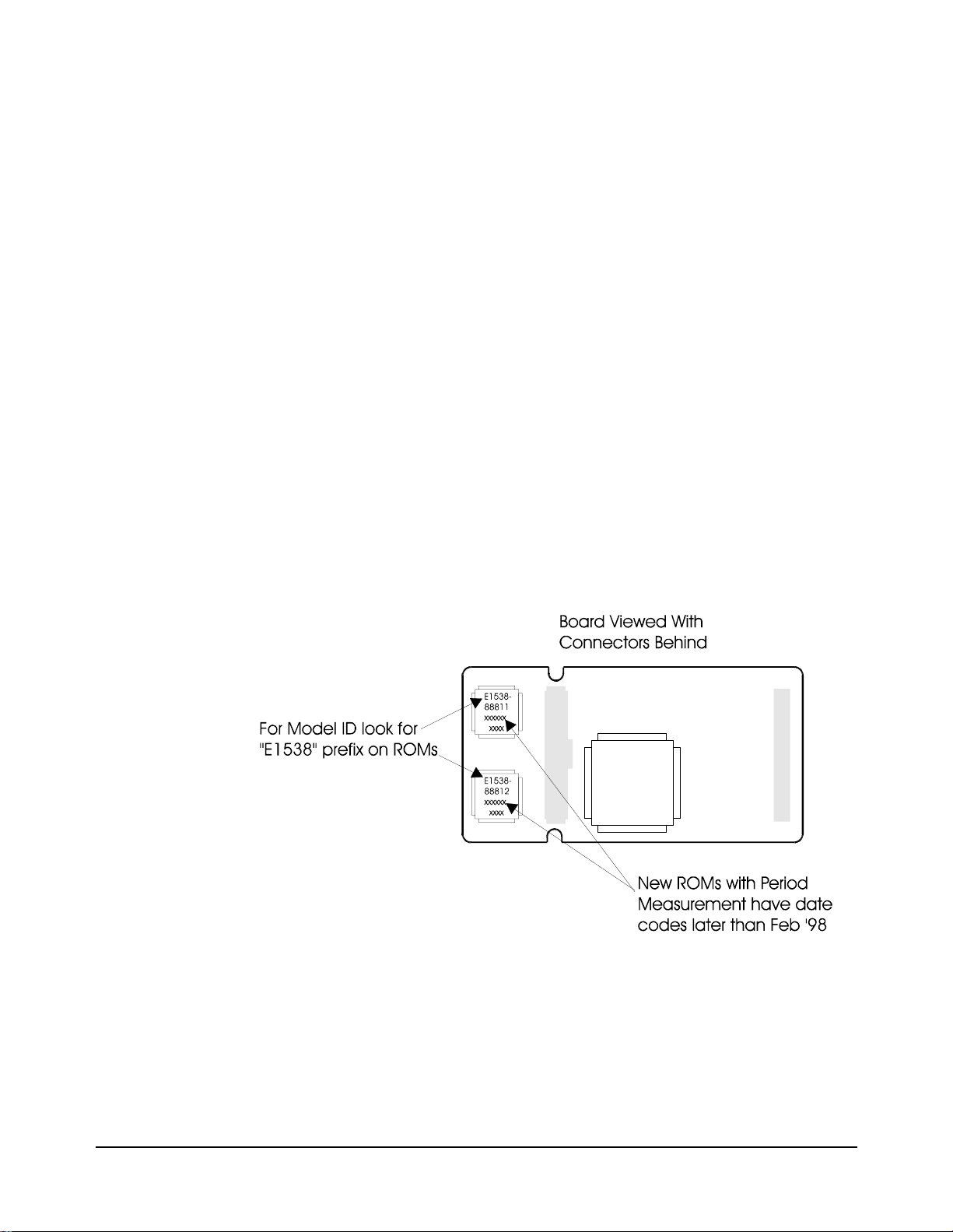
Identifying the Plug-on (IMPORTANT)
There are two versions of the E1538A. The e arly vers ion does not support a
PERiod measurement command set. Early versions have ROM revision
February 1998 and e ar lier . The l at er version adds period me asu re me nt, and
an improved frequency mea surement function. The later v ersions have ROM
revision after February 1998.
In order to access t he additional f unctions of the la ter E1538A, you must us e
one of the following drivers:
•The Plug & Play driver with revision A.02.07 or later
•The Command Module driver with revision A.05.11 or later
To determine the driver revision, execute the *IDN? command.
Figure 1. Identifying the SCP and its ROM Revision
Agilent E1538A Enhanced Frequency/Totalize/PWM SCP 5
Page 10
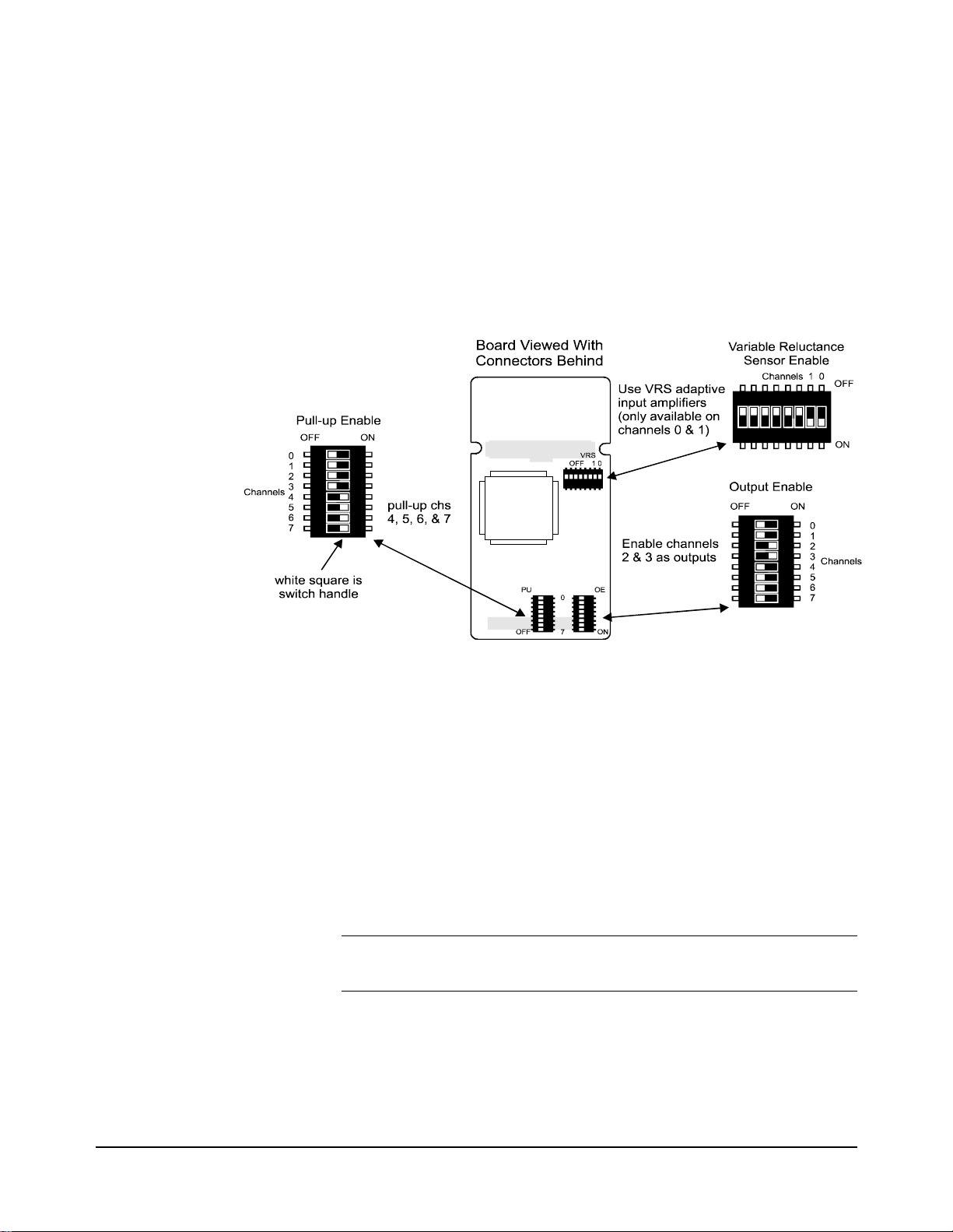
Setting Configuration Switches
The SCP has three packages of eight switches ea ch. The package labele d OE
(Output Enable) determines a channel’s I/O direction. The package labeled
PU (pull-up) controls whethe r or not a channel is float ing or pulled up to an
internal 5V supply. The package labeled VRS (for channels 0 and 1 only)
can enable special input signal conditioning compatible with variable
reluctance sensors. Fo r a discussion on using t he VRS mode, see "VRS Mode
Input Operation" on page 10.
Locating switches Figure 2 shows the location of each channel’s configuration switches.
Configuring Input-
Output direction
Configuring Channel
Pull-up Resistor
Note Pull-Up enable ON is not allowed for channels that have their VRS enable
Figure 2. Switch Location and Example Settings
Refer to Figure 2 for the location of t he eight Output Enable (OE) swit ches.
Move the channel’s switch handle to the ON pos it io n for output, and to t he
OFF position for input.
Refer to Figure 2 for the location of the eight Pull-up Enable (PU) switches.
Move the switch handle to the ON position to connect the pull-up resistor
(connected f rom channel terminal to an internal +5V), and to the OFF
position to disconn ect the pul l-up resis tor (high im pedance input/ open drain
output).
ON (VRS is only available on channels 0 and 1).
6 Agilent E1538A Enhanced Frequency/Totalize/PWM SCP
Page 11
Installation
Installation for this Plug-on is identical to other SCPs and is covered in
Chapter 1 of your Agilent E1415 or E1419 User’s Manual.
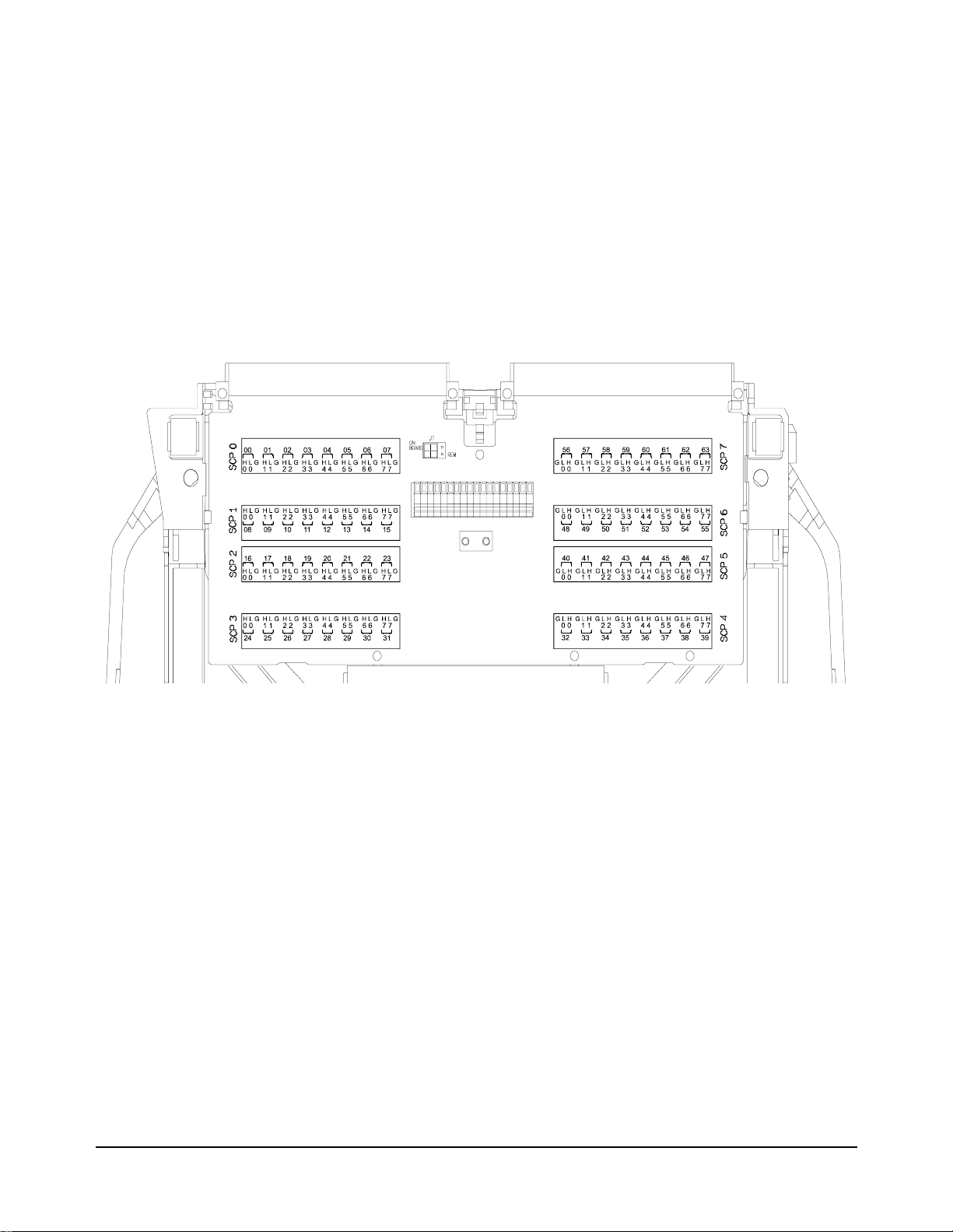
Connecting To The Terminal Module
The SCP connections for the Terminal Modules are shown on the
self-adhesive labels that come with the SCP. Use these to label terminal
definitions on your t erminal module. The connections are shown in Figure 3.
Figure 3. E1538A Terminal Module Connections
Figure 4 shows the screw terminal Option 11 for the E1419A.
Agilent E1538A Enhanced Frequency/Totalize/PWM SCP 7
Page 12
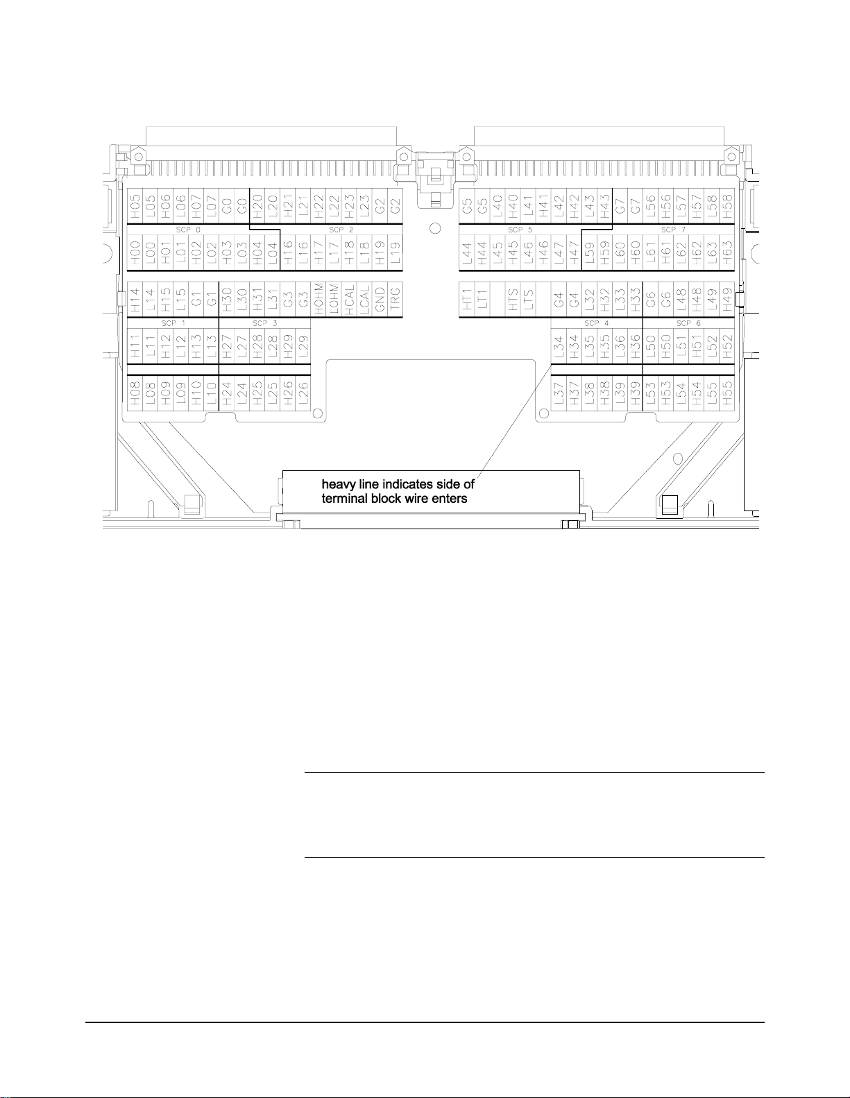
Figure 4. E1419A Option 11 Terminal Module Connections
Recommended Signal Connections
Figure 5 shows the reco mmended meth od of wir ing di gital I/O ch annel s, as
well as the maximum voltage limitation s for the E1538 A.
Figure 5 shows the shields connected directly to the E1415 ground. This is
to limit potential nois e on the digital wiring from affecting low- level analog
channel wiring within the Terminal Module.
Note The G (analog guard) terminals are connected through 10K Ohm resistors
to chassis ground. To connect the shields directly to chassis ground on the
E1415 and the E1419 Option 12 Terminal Module, install the
guard-to-ground jumpers for the E1538 channels
8 Agilent E1538A Enhanced Frequency/Totalize/PWM SCP
Page 13
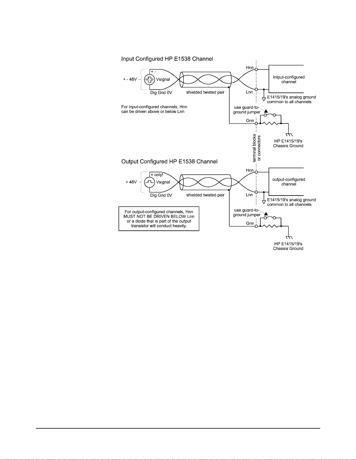
Figure 5. Recommended Connections and Voltage Limits
Input and Output Characteristics
This section describes the E1538’s channel input and output electrical
characteristics. Refer to Figure 6 for the following discussions.
Input Characteris tics When configured for input, E1538 channels provide digital i nput through the
threshold comparator . The digital input threshold l evel is programmable with
a SCPI command from -48 to +47.625 VDC in .375V steps (relative to the
Lnn terminal). The threshold amplifier also provides typically 0.5 volts of
hysteresis regardless of the threshold level setting. The input impedance in
this configuration is greater than 100KΩ (as long as the 10KΩ pull-up resistor
is OFF).
Channels 0 and 1 also provide the cap abi li ty (when the VRS switch is ON)
to read the output of vari able reluctance sensors. Because the ou tput of a VRS
varies in rela tion to the velocity of the toothed wheel it is r eading, the E1538A
provides adaptive ampl ifiers for these channels. The fu nction of the amplifier
Agilent E1538A Enhanced Frequency/Totalize/PWM SCP 9
Page 14
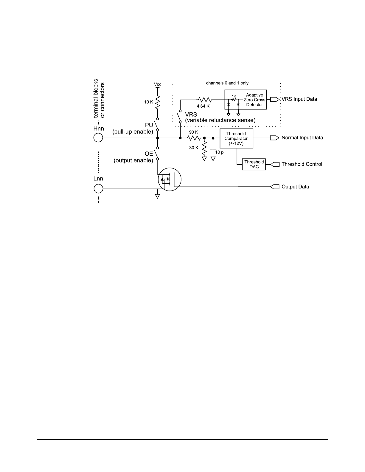
is to maintain a constant-l evel digital o utput while the input varies from
millivolts to several tens of volts.
For simple sensing of switches and open collector logic devices, a channel ’s
pull-up resistor can be connected by closing its PU switch.
Figure 6. The E1538A Input/Output Characteristics
VRS Mode
Input Operation (SCP
channels 0 & 1 only)
Note VRS enable ON is not allowed if PU enable is ON.
When the VRS configuration swit ch is set to on, the input signal conditioning
for that channel is changed to make it compatible with a typical variable
reluctance sensor. The var iable reluctance sensor is common ly used to detect
rotational shaft po sition and/or velocity. Because th e voltage output of a VRS
is proportional t o t he rate of change of a magnetic field, d if fe ren t rotational
velocities genera te different signal ampli tudes. The VRS-configured chann el
detects the negative going zero-crossin g point of the signal. To mini mize the
effects of input nois e, the zer o-crossi ng detecto r can only be tr iggered i f the
positive-going portion of the signal exceeded an "arming" threshold. The
arming circuit is reset whe n zero-cross ing detector is triggered s o it can’t
re-trigger until after the signal exceeds the arming threshold again. The
arming threshold t racks the positive p eak input level and i s 80% of t his peak
value. By sensing th e "zero-crossing" point of t he input signal, the VRS mode
isolates signal amplitude changes from affecting signal timing.
At high rotational speeds, variable reluctance sensors can generate voltage
levels over 100VAC. The VRS i nputs must be protecte d against signal levels
over 17.5 Volts. If your VRS will generate voltages over 17.5, you must
provide a resistor in series with the VRS input. The user-supplied resistor,
together with the VRS input’s 5.38K input impedance form a voltage di vider
that attenuates the input signal at the channel’s Hi input terminal. Use the
10 Agilent E1538A Enhanced Frequency/Totalize/PWM SCP
Page 15

V
formula to calculate the p rotection resis tor’s value.
R
external
---------------------------------------
=
sensor
0.0032
17.5–()
Figure 7 shows the VRS mode input characteristics.
Figure 7. VRS Mode Input Characteristics
Output Characteristics The output stage of the E1538A is simply a MOS FET transistor that is
configured as "open-drain" when the pull-up resistor is not connected (PU
switch is OFF). For simple interfacing to logic devices, the pull-up resistor
can be connected by t urning the PU switch ON. Oper at in g vo lt age s ( out put
transistor off) at an out put-c onfigu red c hannel can range from 0 to 4 8 volt s.
The output can sink up to 100mA of current (output transistor on).
Caution If the Hnn terminal is driven below the Lnn terminal while a
channel is output-configured, an "inherent diode" in the output
transistor will conduct heavily. This reverse current must be
limited to 100mA, or damage to the SCP could result.
Note The *RST and power-on condition (true also after *TST) for output-
configured channels will output a logical one (open-drain output off). You
should keep this behavior in mind when applying the E1415 to your
system. It is best to have your system’s digital inputs use a high (one) as
their safe state.
Programming With SCPI Commands
The SCPI commands shown here conf igure E1538 functions. The E1415 and
E1419 don’t provide SCPI commands to read an input channel or control an
output channel. This communication with the SCP is provided by the
Algorithm Language. Examples will show communicat ion wit h al gori t hms.
Agilent E1538A Enhanced Frequency/Totalize/PWM SCP 11
Page 16

Checking the ID
of the SCP
To verify the SCP type(s) installed on your VXI module, use the
SYSTem:CTYPe? (@<channel>) command.
•The channel parameter specifies a single channel in the channel range
covered by the SCP of inter est. The first chann el number for each of the
eight SCP positions are; 0,8,16,24,32,40,48, and 56.
The value returned for the E1538A SCP is:
HEWLETT-PACKARD,E1538A Enhanced Frequency/Totalize/PWM SCP,0,0
To determine the type of SCP installed on channels 0 through 7 send
Configuring the
Channels
SYST:CTYPE? (@100)
enter statement here
The E1538A has eight digit al channels. The Power -on and *RST state is that
all input-configured channels sense static digital state
(SENS:FUNC:COND), and all output-configured channels output static
digital state (SOUR:FUNC:COND). Logical sense is normal
(INP:POL NORM and OUTP:POL NORM).
query SCP type @ ch 0
enter response string
Configuring I/O Direction Channels are configured for input or output with the I/O direction switches
(see "Setting Configuration Switches" on page 6).
Programming Input
Channels
Setting the Input
Threshold Level
This section deals wit h all asp ects of progr amming inpu t channel functions.
Channels are configured for input with the I/O direction switches (see
"Configuring Input-Output direction" on page 6). A related error message:
3123,"E1538 OE switch ON conflicts with this command."
The E1538 allows progra mmatically setting the input threshold level for each
input configured channel. The input threshold can be set from -46VDC to
+46VDC with .375V resolution. While input polarity is set to NORMAL, an
input level higher than the threshold level is considered a logic one, and an
input level lower than the threshol d level is considere d a logic zero. If input
polarity is set to INVerted, an input level higher than the threshold level is
considered a logic zero and an input level lower than the threshold level is
considered a logic one. To set input threshold level use the command
INPut:THReshold:LEVel <level>,(@<ch_list>)
•<level> is a value between -46 and +46 inclusive. The resolution for
<level> is 0.375 Volts. The *RST and power-on default for <level> is
1.78 volts.
Note The value se nt for <level> will be rounded to the nearest multiple of 0.375
Volts. For instance, 5 would be 4.875, 10 would be 10.125, 9.5 would be
9.375, and 15 would be 15. The INP:THR:LEV? query will return the
actual setting.
12 Agilent E1538A Enhanced Frequency/Totalize/PWM SCP
Page 17

•Channels in <ch_list> must be input configured channels
Determining the Input
Threshold Level
To determine a channel’s input threshold level, use the command:
INPut:THReshold:LEVel? (@<channel>)
Note Because the E1538 rounds <level> to the nearest multiple of 0.375, the
returned value can be different from the value sent.
•<channel> must specify a single input-configured channel.
•INP:THR:LEV? returns a numeric value between -46 and +46. The
C-SCPI type is int32.
To query the threshold level on the second channel at SCP position 4 send:
INP:THR:LEV? (@133)
enter statement here
Set Input Logic Sense Use INPut:POLarity NORMal | INVerted,(@<ch_list>) to configure inp ut
channel logic sense. The operation is as follows:
INP:POL NORM input voltage greater than the threshold level sends a
value of 1 (one) to the algorithm channel specifier.
query 2nd chan on SCP pos. 4
returns threshold value
INP:POL INV input voltage greater than the threshold level sends a
value of 0 (zero) to the algorithm channel specifier.
To configure channels 40 to 43 to sense low input as logic 1
INP:POL INV,(@140:143)
Agilent E1538A Enhanced Frequency/Totalize/PWM SCP 13
Page 18
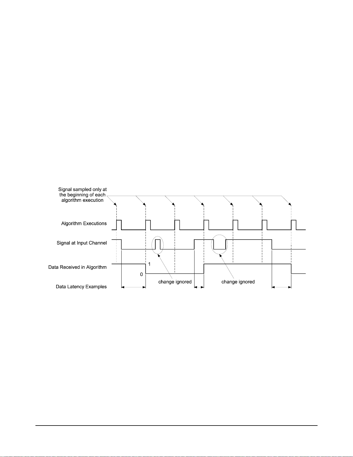
Reading Static
Digital State
This means reading a channel’s current digital state when an algorithm
executes. This is the default function assigned to all digital input channels
after *RST and at power-up. To set individual channels to this function use
the SCPI command [SENSe:]FUNCtion:CONDition (@<ch_list>). The
value returned to an algorithm is a floating point representation of 0 or 1,
depending on the stat e of the input signal and the channel’s INP:POL setting.
To set channels 40 through 43 to input digital states
*RST
SENS:FUNC:COND (@140:143)
ALG:DEF ’ALG1’,’ writecvt(I140,40); writecvt(I141,41); writecvt(142,42);
writecvt(143,43);’
INIT
do loop
SENSE:DATA:CVT? (@40:43)
read 4 CVT values
end loop
default for all dig inputs
Figure 8. Input Static Digital States
14 Agilent E1538A Enhanced Frequency/Totalize/PWM SCP
Page 19
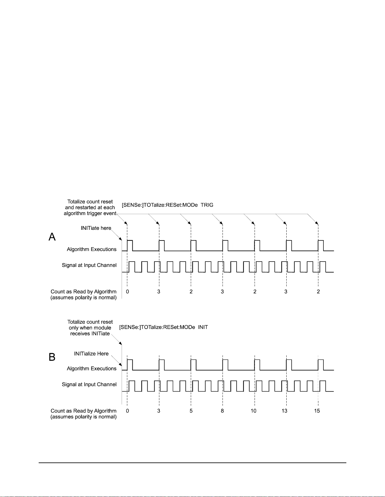
Totalize Positive or
Negative Edge State
Changes
Use [SENSe:]FUNCtion:TOTalize (@<ch_list>) to configure channels to
totalize. Totalize means to simply count state transitions (either positive
going, or negative going). Figure 9 A shows totalizing transitions between
each algorithm executi on. Figure 9 B shows totalizing all transitions starti ng
from the time the module last received an INITiate command.
Use [SENSe:]TOTalize:RESet:MODe INIT | TRIG,(@<ch_list>) to
configure the total ize channel to either reset its count once each trigger e vent,
or only when the module is INI Tiated. Use INP:POL INV to sen se negati ve
edges. The count capacity is 16,777,215 (24-bits, unsigned)
To totalize state changes at channel 44 starting fro m INITiate time
*RST
SENS:TOT:RES:MOD INIT,(@144)
SENS:FUNC:TOT (@144)
ALG:DEF ’ALG1’,’writecvt(I144,44);’
INIT
. . .
SENS:DATA:CVT? (@44)
ch 44 totalize reset at INIT
ch 44 is totalize input
alg sends coun t to CVT
get totalize count from cvt
Figure 9. Input Totalize Count
Agilent E1538A Enhanced Frequency/Totalize/PWM SCP 15
Page 20

About Period and
I
Frequency
Measurements
The E1538A actually measures signal period for both the period and
frequency functions. If the measurement function is set to frequency rather
than period, the SCP returns the recipro cal of the measured period. The
resolution of each per iod measurement is ba sed on the time proce ssor chip’s
timer period (238.4nS). To improve resolution on faster input signals,
multiple signal periods can be measured and averaged. For period
measurements there are two dif fe ren t mode s tha t ca n be used to control the
number of periods to average. For frequency measurements only the
APERture mode is available.
1. The [SENSe:]PERiod:NPERiod mode explicitly sets the number of
signal periods to measure and average. The time it takes the SCP to
return a reading is dependent on the input signal period (for a given
NPERiod setting), longer signal periods take longer to return a
reading.
In NPERiod mode the actual measurement resolution (in seconds) is
fixed while the relati ve r eso lut i on (as a percentage of the inpu t si gna l
period) is variable. That is, when NPERiods is set to provide an
adequate resolution for short period signals, long period signals will
have increased resolution.
2. The APERture mode sets a fixed duration that the SCP will use to
measure multiple signal periods. The actual effective APERture
<time> will be:
<time>
.
--------------------------------
NT
signal_period
signal_period×
The minimum aperture will be 1 signal peri od, and the maximum wil l
be 255 signal periods.
In APERture mode, the effective resolution (in seconds) varies with
the period of the input signal. That is, as the signal period is reduced,
the number of measurements averaged increases, thereby improving
the effective resolution. However, the relative resolution (as a
percentage of the input signal period) is fairly constant with changes
in signal period.
Generally, more measurements (greater NPERiod count or longer APERture
time) means a more accura te frequency value. Of course more measurements
means that the read ing retur ned contains mor e latency (i s “older” in relati on
to the signal's c urrent frequency). To trac k fast changing frequen cy, you have
to trade-off some accuracy with a shorter aperture time.
16 Agilent E1538A Enhanced Frequency/Totalize/PWM SCP
Page 21
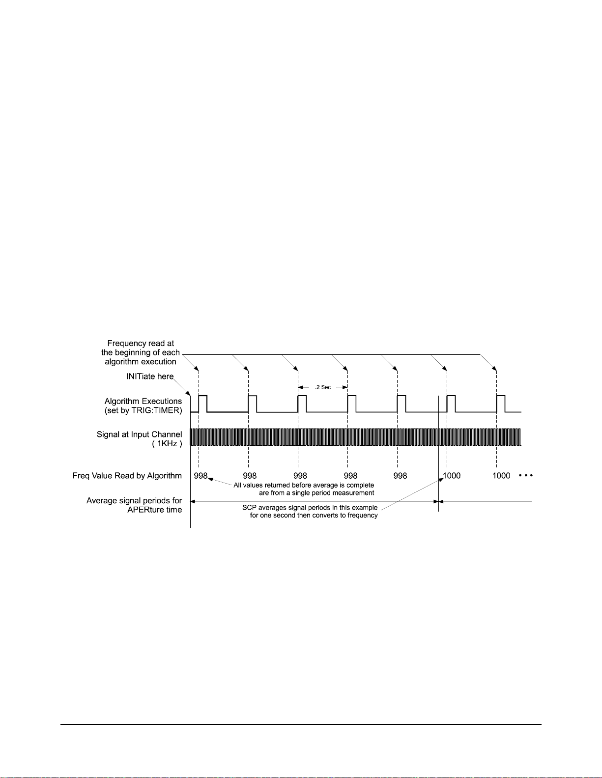
Measure Frequency Use [SENSe:]FREQuency:APERture <time>,(@<ch_list>) to configure
the frequency counter channels’ measurement interval.
Use [SENSe:]FUNCtion:FREQuency (@<ch_list>) to configure channels
to measure signal frequency.
To measure frequency at channel 45 with aperture of 1 second
*RST
TRIGGER:TIMER .2
SENS:FUNC:FREQ (@145)
SENS:FREQ:APER 1,(@145)
ALG:DEF ’ALG1’,’writecvt(I145,45);’
INIT
do loop
SENS:DATA:CVT? (@45)
read value from CVT query above
end loop
Alg executes at .2 sec intervals
ch 45 is frequency counter
meas and avg sig periods for 1S
alg puts frequency in CVT
start algorithm execution
get frequency from CVT
Figure 10. Input Frequency
Agilent E1538A Enhanced Frequency/Totalize/PWM SCP 17
Page 22
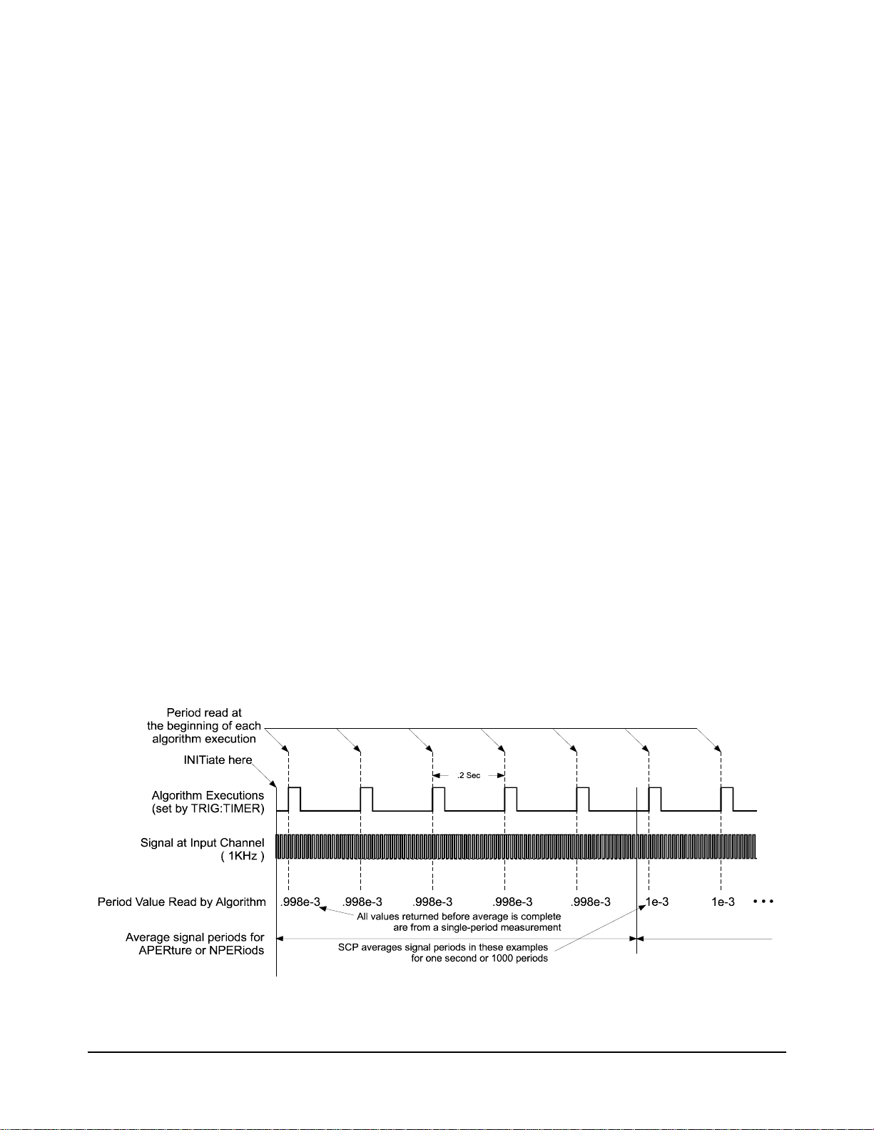
Measure Period Use [SENSe:]PERiod:MODe APERture | NPERiods,(@<ch_list>) to select
the measurement interval setting mode.
Depending on the mode selected above use
[SENSe:]PERiod:APERture <time>,(@<ch_list>) or
use [SENSe:]PERiod:NPERiods <n_periods>,(@<ch_list>) to set the
interval for measuring and averaging signal periods.
For PERiod function, the E1538 spports two distinct measurement ranges:
1. When SENS:PER:RANGE is set to 1sec, the E1538 can measure
periods from 10usec - 1sec . The value of SENS: PER:APER can range
from 10usec - 1sec.
2. When SENS:PER:RANGE is set to 4sec, the E1538 can measure
periods from 40usec - 4sec . The value of SENS: PER:APER can range
from 40usec - 4sec. See SENS:PER:RANGE command on page 61
Use [SENSe:]FUNCtion:PERiod (@<ch_list>) to configure channels to
measure signal period.
To measure the signal period at channel 45 with aperture of 01 second
*RST
TRIGGER:TIMER .2
SENS:FUNC:PER (@145)
SENS:PER:RANGE 1,(@1 45)
SENS:PER:MODE APER(@145)
SENS:PER:APER 1,(@145)
ALG:DEF ’ALG1’,’writecvt(I145,45);’
INIT
do loop
SENS:DATA:CVT? (@45)
read value from CVT query above
end loop
Alg executes at .2 sec intervals
ch 45 to measure signal period
set period range 10µsec - 1sec
set meas and avg interval mode
meas and avg sig periods for 1S
alg puts period in CVT
start algorithm execution
get period from CVT
Figure 11. Input Period
18 Agilent E1538A Enhanced Frequency/Totalize/PWM SCP
Page 23

To measure period at channel 45 as the average of 1000 signal periods:
*RST
TRIGGER:TIMER .2
SENS:FUNC:PER (@145)
SENS:PER:RANGE 1,(@1 45)
SENS:PER:MODE NPER(@145)
SENS:PER:NPER 1000,(@145)
ALG:DEF ’ALG1’,’writecvt(I145,45);’
INIT
do loop
SENS:DATA:CVT? (@45)
read value from CVT query above
end loop
Alg executes at .2 sec intervals
ch 45 to measure signal period
set period range 10µsec - 1sec
set meas interval by n periods
meas and avg 1000 sig periods
alg puts period in CVT
start algorithm execution
get period from CVT
Agilent E1538A Enhanced Frequency/Totalize/PWM SCP 19
Page 24
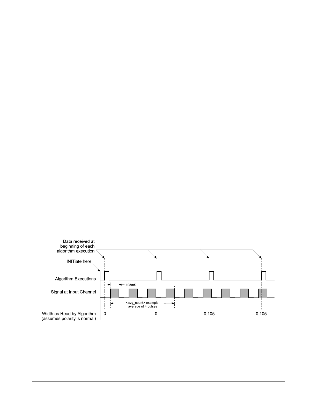
Measure Pulse Width This means that the E1538 will measure the width of the logic 1 portion of
a pulse. The pulse width is sent to the algorithm in units of seconds. To
measure the high portion of a pulse (positive going edge to negative going
edge) set the channel input polarity to INP:POL NORM,(@<ch_list>). To
measure the low port ion of the pulse (negat ive g oing e dge to posit ive go ing
edge) set the channel input polarity to INP:POL INV,(@<ch_list>).
The value returned to an algorithm can be from 5µSec to 1 Second with
59.6nSec resolution.
To configure channels to measure pulse width use the command
[SENSe:]:FUNCtion:PWIDth <avg_count>,(@<ch_list>)
•<avg_count> sets the number of pulses to average when forming the
pulse duration value. More counts give more accurate readings, but
slower response to changing pulse widths.
•<ch_list> specifies the channels that will read pulse widths
To measure pulse width on channels 46&47
*RST
SENS:FUNC:PWID 4,(@146,147)
Algorithm reads the pulse widths on channels 146 and 147 and returns these
values in CVT elements 46 and 47
ALG:DEF ’ALG1’,’writecvt( I146, 46 ); writecvt( I147, 47 );’
INIT
. . .
SENS:DATA:CVT? (@46,47)
read puls width on chs 46&47
start algorithm
read pulse widths from CVT
Figure 12. Measure Pulse Width
20 Agilent E1538A Enhanced Frequency/Totalize/PWM SCP
Page 25

Sense Quadratur e
Position
This means that the E1538 will conv ert a digital quadratur e s ign al pa ir int o
an absolute 24-bit count. The count value can be read by the algorithm.
The E1538’s quadrature position function increments a counter value each
time there is a t ran si tion on either of t he quadrature chann el pai r. W hen the
lower numbered channel’s signal LEADS the higher numbered channel, the
function counts up. When the lower numbered channel LAGS the higher
numbered channel, the function counts down.
To configure a pair of channels to sense quadrature count use
[SENSe:]FUNCtion:QUADrature [<count_preset>,](@<ch_list>)
•<count_preset> if included, allows presetting the absolute counter
associated with the ch anne l pair . All qua dratu re pairs i n <c h_lis t> will
be preset to the same value. If not included, the default count at
algorithm start will be zero. <count_preset> can range from 0 to
16,777,215. The variable type is int32
•<ch_list> must always specify both channels of a pair. More than one
pair can be specified. Both channels of any pair must be adjacent.
<ch_list> can specify channels on more than one E1538. The channel
numbers in <ch_list> must be in ascending order. The related error
messages are:
3115, "Channels specified are not in ascending order."
3116, "Multiple channels specified are not grouped correctly."
3117, "Grouped channels are not adjacent."
3122, "This multiple channel function must not span multiple SCPs."
The algorithm reads the current count through the low numbered
channel. The count is an unsigned 24-bit value ranging from 0 to
16,777,215. The counter can roll over from 16,777,2215 to 0, and roll
under from 0 to 16,777,215 is 16,777,215.
To configure channels 42 and 43 as one qua drature pair, and channels 48 and
49 as another pair
*RST
SENS:FUNC:QUAD 8192,(@142,143)
SENS:FUNC:QUAD 0,(@148,149)
algorithm will retrieve values from input channels and place in CVT elements
ALG:DEF ’ALG1’,’writecvt(I142,42); writecvt(I148,48);’
INIT
begin loop
SENS:DATA:CVT? (@42,48)
display or otherwise use count info
end loop
pair 42&43 preset to count of
8192
pair 48&49 preset to 0
start algorithm execution
loops between here and end loop
get quadrature position coun t
Agilent E1538A Enhanced Frequency/Totalize/PWM SCP 21
Page 26
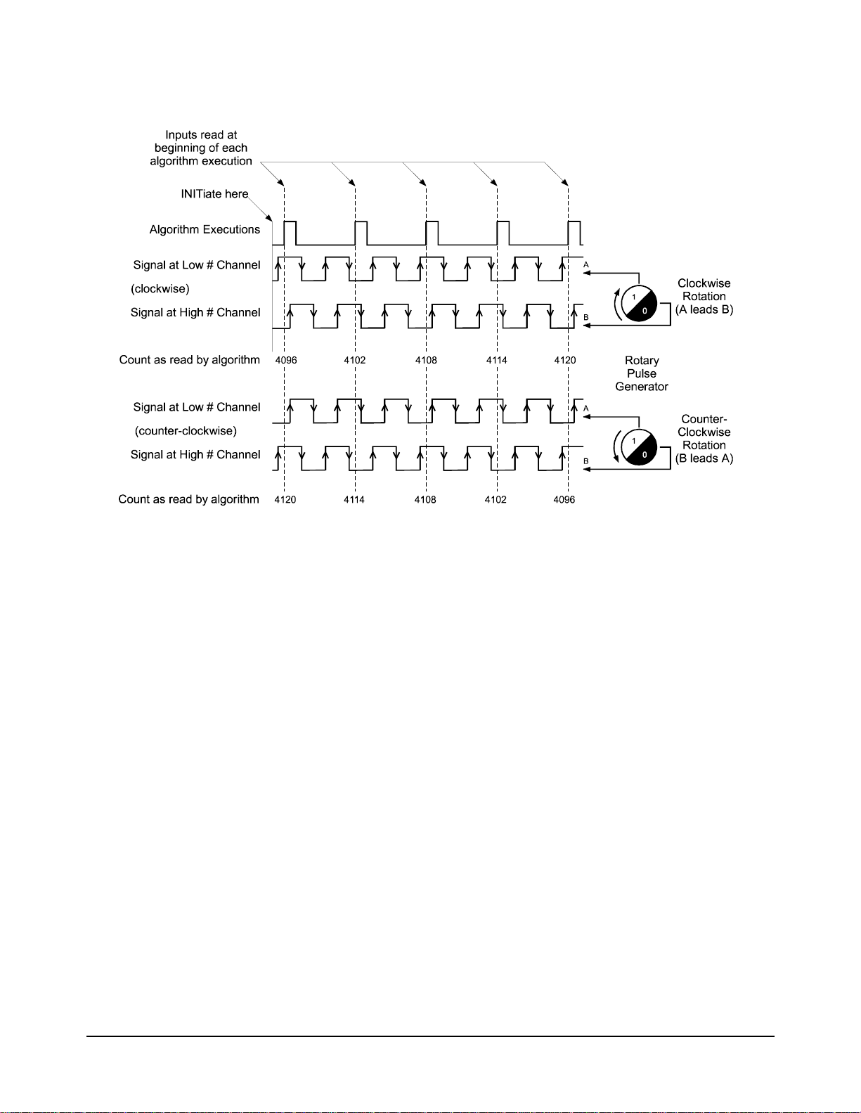
Figure 13. Sense Quadrature Position
Sense Rotational Velocity This means that th e E1538 will read the rota tional velocity of a toothed wheel
sensor. The E1538 measures too th-to-toot h period and conve rts it int o units
of revolutions per second (RPS). This function can only be linked to the
E1538’s first channel. The function works for wheels that h ave either a
missing, or an extra tooth to mark their index position. Figure 14 shows a
wheel sensed with a variabl e reluctance sensor (using the VRS input option),
but any wheel sensing method is applicable as long as it provides a digital
output to the RVEL channel.
The value read by the algorithm can range from RPS to RPS.
As well as sensing rotational velocity, SENS:FUNC:RVEL provides the
reference position to the SOUR:FUNC:RPULse function that generates
angular positioned pulses. See page 30 for more informat ion on RPULse.
To assign a channel to sense rotational velocity, use the command:
[SENSe:]FUNCtion:RVELocity <n_teeth>,<index_type>,(@<ch_list>)
•<n_teeth> is the number of teeth that the wheel would have if it didn’t
have missing or e xtra teeth. For example, we would set <n_tee th> to 12
for the wheel shown in Figure 14, eve n t houg h wi th the missing tooth,
there are only 11. <n_teeth> can range from 3 to 255.
22 Agilent E1538A Enhanced Frequency/Totalize/PWM SCP
1
-------------nteeth
100 000,
-------------------- nteeth
Page 27

•<index_type> can be either of the strings "MISSing", or "EXTRa"
•<ch_list> must be the first channel on the SCP, but can contain more
than one channel provided that each c hannel is on a separat e
following note. The related Error Messages are:
3110, "Channel specified is invalid for RVELocity function.
Note Only one channel on any E1538 SCP can be assigned to the
SENS:FUNC:RVEL function, and it must be the first channel on the SCP."
E1538. See
Figure 14. Sense Rotational Velocity
Example of Rotational Velocity Sense
Channel 40 senses RVEL and the algorithm reads and returns the velocity
value in CVT element 40
*RST
SENSE:FUNC:RVEL 12,MISSING,(@140)
ALG:DEF ’ALG1’,’writecvt(I140,40);’
INIT
loop always
SENS:DATA:CVT? (@40)
display the RVEL value
end loop
Agilent E1538A Enhanced Frequency/Totalize/PWM SCP 23
12 toothed wheel with one
missing, from channel 40
simply puts value from ch 40 into
CVT element 40
start the algorith m
will loop from "end loop" to here
query the value from CVT 40
Page 28

Programming Output
Channels
This section deals wi th all aspects of progr amming output channel func tions.
Channels are configured for output with the I/O direction switches (see
"Configuring Input-Output direction" on page 6). A related error message:
3124, "E1538 OE switch OFF conflicts with this command."
Controlling Output
Polarity
Output Static
Digital State
Use OUTPut:POLarity NORMal | INVerted,(@<ch_list>) to configure
output channel logic sense. The operations is as follows:
OUTP:POL NORM a logical 1 output from the algorithm, or generated
within the E1538 (single or repetitive pulses) will
turn off the output transistor (can be pulled up).
OUT:POL INV a logical 1 output from the algorithm, or generated
within the E1538 (single or repetitive pu lses) will turn
off the output transistor (pulls low).
To configure channels 40 to 43 to drive their outputs low for a logic 1
OUTP:POL INV,(@140:143)
This means setting a channel’s digital state when an algorithm executes. To
set individual channels to this function use the SCPI command
SOURce:FUNCtion[:SHAPe]:CONDition (@<ch_list>)
To configure channels 40 through 43 as static digital outputs, send
*RST
SOUR:FUNC:COND (@140:143)
ALG:DEF ’ALG1’,’static float ch0=0, ch1=1, ch2=0, ch3=1; O140=ch0;
O141=ch1; O142=ch2; O143=ch3;’
INIT
default for all digital outputs
Figure 15. Output Static Levels
24 Agilent E1538A Enhanced Frequency/Totalize/PWM SCP
Page 29

Variable Width Pulse Per
Trigger
This means that the channel generates a pulse whose width is specified by
the algorithm each time the algorithm executes. The value sent by the
algorithm can range from 7.87µSec to 7.812mSec.
The command sequence to se t-up this mode is:
SOURce:FUNCtion:PULSe (@<ch_list>) to ena ble pulse generation.
the following two commands return the E1538 to the Single pulse-per-trigger
mode from either the FM or Pulse Width Modulation modes. Since Single
pulse-per-trigger is the default pulse mode at power-up or after *RST, only *RST
then SOUR:FUNC:PULS (@<ch_list>) are actually need ed.
SOURce:FM[:STATe] OFF,(@<ch_list>) to disable FM mode.
SOURce:PULM[:STATe] OFF,(@<ch_list>) to disable PWM mode.
To configure channel 44 to outpu t a single contr olled width pulse per trigger
*RST
after *RST, sour:func:puls is all that is required to enable the default single
pulse-per-trigger mode.
SOUR:FUNC:PULS (@144)
ALG:DEF ’ALG1’,’static float outpulse=0.001; O144=outpulse;’
INIT
. . .
ALG:SCAL ’ALG1’,’outpulse’,5E-4
ALG:UPDATE
channel sources puls es...
start alg execution
.5ms pulse
Figure 16. Output Variable Width Pulse per Trigger
Agilent E1538A Enhanced Frequency/Totalize/PWM SCP 25
Page 30

Variable Width Pulse
Train (PWM)
This means that the E1538 ou tputs a conti nuous t rain of pulse s whose l ogic
1 pulse width is control led by the a lgorithm. Th e frequenc y is set by a SCPI
command before INIT. Use the fol lowing command sequen ce to set up this
mode:
SOURce:FUNCtion:PULSe (@<ch_list>) to ena ble pulse generation.
SOURce:PULM[:STATe] ON,(@<ch_list>) to select the PWM mode
SOURce:PULSe:PERiod <period>,(@<ch_list>) to set the pu lse repetition
period (frequency = 1/<period>). <period> can range from 25µSec to
7.812mSec.
The pulse width value sent by the algorithm can range from 7.87µSec to
<period>-7.87µSec. Resolution within this range is 238.4nSec.100%
duty-cycle is output whe n t he algorithm sends a val ue gre at er tha n or e qual
to <period>. 0% duty-cycle is out put when t he algo rithm s ends a val ue les s
than or equal to 0.
To configure channel 45 to output a variable pulse width continuous train
SOUR:FUNC:PULS (@145)
SOUR:PULM ON,(@145)
SOUR:PULS:PER .0005,(@145)
channel sources puls es...
and continuous PWM train
.5 msec period (2KHz freq)
The algorithm can now output a value to channel 45 to control pulse width
of the logic 1 portion of the waveform:
O145 = 333E-6 /* channel 45 pulse width will be 333 µsec */
Figure 17. Output Pulse-Width-Modulated Signal
26 Agilent E1538A Enhanced Frequency/Totalize/PWM SCP
Page 31

Variable Frequency Fixed
Width Pulse Train (FM)
This means that the E1538 outputs a continuous train of pulses whose
frequency is control led by the alg orithm. The logi c 1 level pulse wi dth is set
by a SCPI command before INIT. Use the following command sequence:
SOURce:FUNCtion:PULSe (@<ch_list>) to ena ble pulse generation.
SOURce:FM[:STATe] ON,(@<ch_list>) to select the FM mode.
SOURce:PULSe:WIDTh <width>,(@<ch_list>) to pre-set the pulse widt h
of the logic 1 porti on of the wavefo rm. <widt h > can range f rom 7.87µSec t o
7.812mSec.
The frequency value sent by the algorithm can range from 128Hz to 40KHz.
2
f
out
The frequency resolution is
---------------------------
4.194 MHz
To configure channel 45 to outp ut vari able fre quency co ntinuo us t rain with
fixed pulse width
SOUR:FUNC:PULS (@145)
SOUR:FM ON,(@145)
SOUR:PULS:WIDT .001,(@145)
channel sources puls es...
and continuous pulse train
1 msec fixed pulse width
The algorithm can now output a frequency value to channel 45:
O145 = 250 /* channel 45 will source 250 Hz pulse train */
Figure 18. Output Fixed Pulse Width Variable Frequency (FM)
Agilent E1538A Enhanced Frequency/Totalize/PWM SCP 27
Page 32

Variable Frequency
Square-Wave Pulse Train
(FM)
This means that the E1538 outputs a continuous train of pulses whose
frequency is control led by the algorithm. The the dut y-cycle of the waveform
is always 50%. Use the following command sequence:
SOURce:FUNCtion:SQUare (@<ch_list>) to enable square-wave
generation.
SOURce:FM[:STATe] ON,(@<ch_list>) to se lect the FM mod e.
The frequency value sent by the algorithm can range from 64Hz to 40KHz.
2
f
out
The frequency resolution is
---------------------------
4.194 MHz
To configure channel 45 to outpu t variable freque ncy continuous tr ain with
50% duty cycle (square wave)
SOUR:FUNC:SQUARE (@145)
SOUR:FM ON,(@145)
channel sources square wave...
and continuous PWM train
The algorithm can now output a frequency value to channel 45:
O145 = 2000 /* channel 45 will source 2 KHz square wave */
Figure 19. Output Square Wave Variable Frequency (FM)
28 Agilent E1538A Enhanced Frequency/Totalize/PWM SCP
Page 33

Rotationally Positioned
Pulse Output
This means that the E1538 will gene rate pulses which are positioned by angle
(usually shaft angle). The rotational pulse function requires a rotational
reference, and this is provided by the SENS:RVEL function fr om the SCP’s
first channel. Ther e are four rela ted co mmands that set u p rota tiona l pulses .
Combinations of these commands can set up four different rotational pulse
modes. Figure 20 shows these modes and the command sequence for each.
Following Figu re 20 is the command reference fo r all four comman ds.
Following that are examples of each of the four modes.
Figure 20. Four Modes of Rotationally Positioned Pulses
Agilent E1538A Enhanced Frequency/Totalize/PWM SCP 29
Page 34

Rotational Pulse
Command Usage
Use SOURce:FUNCtion:RPULse (@<ref_channel>),(@<ch_list>) to
link channels in <ch_list> to the rotational pulse function. The channel in
<ref_channel> will be linked to the SENS:FUNC:RVEL function to provide
the rotational reference information to SOUR:FUNC:RPUL.
The commands:
SOURce:RPULse:POSition[:ANGLe] <degrees>,(@<ch_list>),
SOURce:RPULse:WIDTh[:ANGLe] <degrees>,(@<ch_list>), and
SOURce:RPULse:WIDTh:TIME <seconds>,(@<ch_list>) fix the
channels’ rotational pulse position (SOUR:RPUL:POS:ANGL), or the
rotational pulse wi dth (SOUR:RPUL:WIDT:ANGL and :TI ME) bef ore the
INITiate command. The remaining pulse property - the property NOT
specified in one of these commands - will be controlled withi n the algorit hm.
•<ch_list> specif ies the SOUR:FUNC:RPUL chan nel(s) tha t will be set
to the property specified by the command syntax.
•For pulse position, <degrees> can range from -33, 554,430 to 33,554,430
degrees, with a resolution of 1 degree. The pulse is positioned at
<degrees> modulo 360.
For pulse width, <degrees> can range from 0 to 360 degrees, with a
resolution of 1 degree.
•<time> specifi es pulse width in se conds, ranging from .0 0000787 (7.87
µS) to .015624 (15.624mS), with a resolution of 238.4nS
The command:
SOUR:RPULse:VARType ANG Le | TIME,(@<ch_list>) specifies the
type of value that will be controlled (varied) by the algorithm.
•ANGLe specifies that the algorithm will send values of angle (in
degrees) to the channel(s).
TIME specifies tha t the algor ithm will send va lues of time (in seconds)
to the channel(s).
•<ch_list> specifies the SOUR:FUNC:RPUL channel(s) that will be
controlled (varied) by the algorithm.
30 Agilent E1538A Enhanced Frequency/Totalize/PWM SCP
Page 35

Rotational Pulse Mode:
Variable Angular Position, Preset Pulse Width (by angle)
In this mode, the angula r position of the pulses is cont rolled by the algorithm,
and the width (durat ion in degr ees) is pre set before INI T. See Figure 21.Use
the following command sequence:
SOURce:FUNCtion:RPULse (@<ref_channel>),(@<ch_list>) to select the
channels that will output angular positioned pulses, and to specify the
reference channel.
SOURCe:RPULse:WIDTh[:ANGLe] <degrees>,(@<ch_list>) to preset
the pulse width in degrees. The algorithm will control the angular pulse
position.
Example of variable position, preset width (by angle):
Set up channel 40 as the reference channel, and channels 45 through 47 to
output variable position pulses:
*RST
SENS:FUNC:RVEL 12,MISS,(@140)
SOUR:FUNC:RPULSE (@140),(@145:147)
SOUR:RPULSE:WIDT:ANGL 15,(@145:147)
Algorithm outputs pulses on al l three channels with variable position.
ALG:DEF ’ALG1’,’static float Pos1, Pos2, Pos3;O145 = Pos1; O146 =
Pos2;O147 = Pos3;’
ALG:SCALAR’ALG1’,’Pos1’,60
ALG:SCALAR’ALG1’,’Pos2’,180
ALG:SCALAR’ALG1’,’Pos3’,300
ALG:UPDATE
INIT
•
•
•
ALG:SCALAR 'ALG1','Pos1',NewPos1
ALG:SCALAR 'ALG1','Pos2',NewP os2
ALG:SCALAR 'ALG1','Pos3',NewP os3
ALG:UPDATE
sense rvel for reference channel
3 rotational pulse output chans
preset pulse width to 15 degrees
preset ch 45’s pulse pos to 60°
preset ch 46’s pulse pos to 180°
preset ch 47’s pulse pos to 300°
.
start algorithm execution
calculate values for NewPos(n)
later, adjust channel 45’s
position while algorithm running
later, adjust channel 46’s
position while algorithm running
later, adjust channel 47’s
position while algorithm running
values in update queue sent to
variables
Agilent E1538A Enhanced Frequency/Totalize/PWM SCP 31
Page 36

Figure 21. Variable Position, Width Preset by Angle
Rotational Pulse Mode:
Variable Angular Position, Preset Pulse Width (by time)
In this mode, the angula r position of the pulses is cont rolled by the algorithm,
and the width (duration in seconds ) is preset before INIT. See Figure 22. Use
the following command sequence:
SOURce:FUNCtion:RPULse (@<ref_channel>),(@<ch_list>) to select the
channels that will output angular positioned pulses, and to specify the
reference channel.
SOURCe:RPULse:WIDTh:TIME <seconds>,(@<ch_list>) to preset the
pulse width in second s. The algorithm will control th e angular pulse positi on.
Example of variable position, preset width:
Set up channel 40 as the reference channel, and channels 45 through 47 to
output variable position pulses:
*RST
SENS:FUNC:RVEL 12,MISS,(@140)
SOUR:FUNC:RPULSE (@140),(@145:147)
SOUR:RPULSE:WIDT:TIME .001,(@145:147)
Algorithm outputs pulses on al l three channels with variable position.
ALG:DEF ’ALG1’,’static float Pos1, Pos2, Pos3;O145 = Pos1; O146 = Pos2;
O147 = Pos3;’
ALG:SCALAR’ALG1’,’Pos1’,60
ALG:SCALAR’ALG1’,’Pos2’,180
sense rvel for reference channel
3 rotational pulse output chans
preset pulse width to 1 millisec.
preset ch 45’s pulse pos to 60°
preset ch 46’s pulse pos to 180°
32 Agilent E1538A Enhanced Frequency/Totalize/PWM SCP
Page 37

ALG:SCALAR’ALG1’,’Pos3’,300
ALG:UPDATE
INIT
•
•
•
ALG:SCALAR 'ALG1','Pos1',NewPos1
ALG:SCALAR 'ALG1','Pos2',NewP os2
ALG:SCALAR 'ALG1','Pos3',NewP os3
ALG:UPDATE
preset ch 47’s pulse pos to 300°
.
start algorithm execution
calculate values for NewPos(n)
later, adjust channel 45’s
position while algorithm running
later, adjust channel 46’s
position while algorithm running
later, adjust channel 47’s
position while algorithm running
values in update queue sent to
variables
Figure 22. Variable Position, Width Preset by Time
Rotational Pulse Mode:
Var iabl e Pu lse Width (by angle), Preset Angular Position
In this mode, the an gular puls e width is control led by the algorithm, and the
angular position is preset before INIT. See Figure 23. Use the following
command sequence:
SOURce:FUNCtion:RPULse (@<ref_channel>),(@<ch_list>) to select the
channels that will output angular positioned pulses, and to specify the
reference channel.
Agilent E1538A Enhanced Frequency/Totalize/PWM SCP 33
Page 38

SOURce:RPULse:POSition[:ANGLe] <degrees>,(@<ch_list>), to preset
the angular pulse position in degrees. The algorithm will control the pulse
duration.
SOUR:RPULse:VARType ANGLe,(@<ch_list>) to set the type of value
that will vary with algorithm control (in this case pulse width ANGLe).
Example of variable width (by angle), preset position:
Set up channel 40 as the reference channel, and channels 45 through 47 to
output variable width pulses:
*RST
SENS:FUNC:RVEL 12,MISS,(@140)
SOUR:FUNC:RPULSE (@140),(@145:147)
SOUR:RPULSE:POS:ANGL 20,(@145)
SOUR:RPULSE:POS:ANGL 140,(@14 6)
SOUR:RPULSE:POS:ANGL 260,(@14 7)
SOUR:RPULSE:VART ANGL,(@145:147)
Algorithm outputs pulses on al l three channels with variable width.
ALG:DEF ’ALG1’,’static float Width1, Width2, Width3;O145 = Width1; O146
= Width2; O147 = Width3;’
ALG:SCALAR’ALG1’,’Width1’,5
ALG:SCALAR’ALG1’,’Width2’,10
ALG:SCALAR’ALG1’,’Width3’,15
ALG:UPDATE
INIT
•
•
•
ALG:SCALAR 'ALG1','Width1',NewWidth1
ALG:SCALAR 'ALG1','Width2',NewWidth2
ALG:SCALAR 'ALG1','Width3',NewWidth3
sense rvel for reference channel
3 rotational pulse output chans
preset channel 45 pulse posit ion
to 20 degrees
preset channel 46 pulse posit ion
to 140 degrees
preset channel 47 pulse posit ion
to 260 degrees
algorithm will contro l pulse
width by ANGLE
preset ch 45’s pulse width to 5°
preset ch 46’s pulse width to 10°
preset ch 47’s pulse width to 15°
.
start algorithm execution
calculate NewWidth(n)
later, adjust channel 45’s width
while algorithm is running
later, adjust channel 46’s width
while algorithm is running
later, adjust channel 47’s width
while algorithm is running
ALG:UPDATE
34 Agilent E1538A Enhanced Frequency/Totalize/PWM SCP
Page 39

Figure 23. Fixed Position, Variable Width by Angle
Rotational Pulse Mode:
Variable Pulse Width (by time), Preset Angular Position
In this mode, the pulse durati on (in sec onds) is controlle d by the alg orith m,
and the angular position is preset before INIT. See Figure 24. Use the
following command sequence:
SOURce:FUNCtion:RPULse (@<ref_channel>),(@<ch_list>) to select the
channels that will output angular positioned pulses, and to specify the
reference channel.
SOURce:RPULse:POSition[:ANGLe] <degrees>,(@<ch_list>) to preset
the angular pulse position in degrees. The algorithm will control the pulse
duration.
SOUR:RPULse:VARType TIME,(@<ch_list>) to set the type of value that
will vary with algorithm control (in this case pulse duration in seconds).
Example of variable width (by time), preset position:
Set up channel 40 as the reference channel, and channels 45 through 47 to
output variable width pulses:
*RST
SENS:FUNC:RVEL 12,MISS,(@140)
SOUR:FUNC:RPULSE (@140),(@145:147)
SOUR:RPULSE:POS:ANGL 20,(@145)
Agilent E1538A Enhanced Frequency/Totalize/PWM SCP 35
sense rvel for reference channel
3 rotational pulse output chans
preset channel 45 pulse posit ion
to 20 degrees
Page 40

SOUR:RPULSE:POS:ANGL 140,(@146)
SOUR:RPULSE:POS:ANGL 260,(@14 7)
SOUR:RPULSE:VART TIME,(@145:147)
Algorithm outputs pulses on al l three channels with preset duration.
ALG:DEF ’ALG1’,’static float Width1, Width2, Width3;O145 = Width1; O146
= Width2; O147 = Width3;’
ALG:SCALAR’ALG1’,’Width1’,.005
ALG:SCALAR’ALG1’,’Width2’,.010
ALG:SCALAR’ALG1’,’W id t h3 ’,.015
ALG:UPDATE
INIT
•
•
•
ALG:SCALAR 'ALG1','Width1',NewWidth1
ALG:SCALAR 'ALG1','Width2',NewWidth2
ALG:SCALAR 'ALG1','Width3',NewWidth3
ALG:UPDATE
preset channel 46 pulse posit ion
to 140 degrees
preset channel 47 pulse posit ion
to 260 degrees
algorithm will contro l pulse
duration by TIME
preset ch 45 pulse width to 5ms
preset ch 46 pulse width to 10ms
preset ch 47 pulse width to 15ms
start algorithm execution
calculate NewWidth(n)
later, adjust channel 45’s width
while algorithm is running
later, adjust channel 46’s width
while algorithm is running
later, adjust channel 47’s width
while algorithm is running
values in update queue sent to
variables
Figure 24. Fixed Position, Variable Widt h by Time
36 Agilent E1538A Enhanced Frequency/Totalize/PWM SCP
Page 41

Stepper Motor Control Use the command
SOURce:FUNCtion:STEPper <preset_pos>,<mode>,<max_vel>,<min_vel
>,(@<ch_list>)
to control stepper motor s. The E1538 can operate 2 or 4 pha se motors in full,
and half step mode. Position values are sent from the algorithm to the first
channel of a 2 or 4 channel "motor gr oup" . The al gor it hm rea d s t he cur re nt
position from the second channel of the group.
Four-phase stepper motors that require less than 100mA phase current can
be directly driven by the SCP. See Figure 29 for a connection diagram that
also shows the required user-supplied output protection components.
•<preset_pos> defines the position count at algorithm start-up.
•<mode> is used to select the stepping mode. the allowable values are:
<mode> string Stepping Mode Speed Channel
MFSFC2 Full Full 2
FSFC4 Full Full 4
M
FSHC2 Full Half 2
M
MFSHC4 Full Half 4
Table 1. Stepping <mode> values
HSFC2 Half Full 4
M
•<min_vel> is s pecified in steps per second and is the beg inning step rate
at the start of the 14 or 38 s tep ramp-up to <max_vel>.
<max_vel> is specified in steps per second and is the maximum step
rate that will be sent to the motor after ramp-up is complete.
Figure 25 show s the relationship betwe en these parameters. A rela ted
error message: 3120, "Minimum velocity parameter must not exceed
maximum velocity parameter."
Figure 25. Relationship of
min_vel
, and
max_vel
•<ch_list> specifies the channels that will control stepper motors. A
Agilent E1538A Enhanced Frequency/Totalize/PWM SCP 37
Page 42

motor phase channel group can not be split across SCPs.
The algorithm sends new position values to the first channel in a
motor-group. The algorithm reads the current position value from the
second channel in the motor-group.
Example of full step, full speed, 4 phase stepper motor operation:
*RST
preset count to 0, full step, half s peed, 4 channe l, min speed 64s/s,
max speed 256s/s (in half speed mode, actual speed=half specified speed)
SOUR:FUNC:STEP 0,MFSFC4,128,512,(@144:147)
SENS:FUNC:VOLT (@100 )
Algorithm reads voltage a t channel 00, multiplies it by 100 t o derive the value
to send to the motor. Only when the expected motor position (previously sent to
ch44) and the actual motor posit i on (read from ch 45) agree, is a new motor
position is sent to ch44.
ALG:DEF ’ALG1’,’static float MotorDrive;MotorDrive = ( I100 * 100 ) - 512;
/*5.12V =0 MtrDrv */
If ( !(O144 - I145) ) O144 = MotorDrive;’
INIT
channel 0 rea ds voltage
start algorithm
The following figures show the step waveforms for the five built-in step
modes.
Figure 26. Full Step Mode, Full and Half Speed, 2-Channel
38 Agilent E1538A Enhanced Frequency/Totalize/PWM SCP
Page 43

Figure 27. Full Step Mode, Full and Half Speed, 4-Channel
Figure 28. Half Step Mode, Full Speed, 4-Channel
Agilent E1538A Enhanced Frequency/Totalize/PWM SCP 39
Page 44

Figure 29. Directly Driving 4-Phase Stepper Motors
40 Agilent E1538A Enhanced Frequency/Totalize/PWM SCP
Page 45

*RST and *TST (important!)
The *RST and power-on condition (true also after *TST) for outputconfigured channels will output a logical one (open-drain output off). You
should keep this behavior in mind when applyi ng the E1415 to your system.
It is best to have your system’s digital inputs use a high (one) as their safe
state.
Agilent E1538A Enhanced Frequency/Totalize/PWM SCP 41
Page 46

SCPI Command Reference
Most of the E1538’s co mmands were available since its introduction. A small
number of commands are only available with E1538’s built after February
1998. The following table indicates these new commands with an X in the
"for newer units only" column. See "Identifying the Plug-on" on page 5
Table 2.
Command Syntax For newer
units only
INPut:POLarity NORM | INV,(@<
INPut:POLarity? (@<ch_list>) 44
INPut:THReshold[:LEVel] <level>,(@<ch_list>) 45
INPut:THReshold[:LEVel]? (@<channel>) 45
[SENSe:]FUNCtion:CONDition (@<ch_list>) 50
[SENSe:]FUNCtion:FREQuency (@<ch_list>) 51
SENSe:FREQuency:APERture <time>,(@<ch_list>) 47
SENSe:FREQuency:APERture? (@<channel>) 48
SENSe:FREQuency:LIMit:LOWer <freq_limit>,(@<ch_list>) X 48
SENSe:FREQuency:LIMit:LOWer? (@<channel>) X 50
[SENSe:]FUNCtion:PERiod (@<ch_list>) X 51
SENSe:PERiod:APERture <time>,(@<ch_list>) X 56
SENSe:PERiod:APERture? (@<channel>) X 57
SENSe:PERiod:LIMit:UPPer <per_limit>,(@<ch_list>) X 57
SENSe:PERiod:LIMit:UPPer? (@<channel>) X 59
SENSe:PERiod:MODE APERture | NPERiods,(@<ch_list>) X 59
SENSe:PERiod:MODE? (@<channel>) X 60
SENSe:PERiod:NPERiods <count>,(@<ch_list>) X 60
SENSe:PERiod:NPERiods? (@<channel>) X 61
SENSe:PERiod:RANGe[:UPPer] <count>,(@<ch_list>) X 61
SENSe:PERiod:RANGe[:UPPer]? (@<channel>) X 62
ch_list
>)
Page
Discussed
44
[SENSe:]FUNCtion:PWIDth <avg_count>,(@<ch_list>) 52
[SENSe:]FUNCtion:QUADrature [<preset_count>,](@<ch_list>) 52
[SENSe:]FUNCtion:RVELocity <n_teeth>,<index_type>,(@<ch_list>) 53
[SENSe:]FUNCtion:TOTalize (@<ch_list>) 55
[SENSe:]TOTalize:RESet:MODE INIT | TRIG,(@<ch_list>) 62
42 Agilent E1538A Enhanced Frequency/Totalize/PWM SCP
Page 47

Table 2.
Command Syntax For newer
units only
[SENSe:]TOTalize:RESet:MODE? (@<channel>) 63
OUTPut:POLarity NORM | INV,(@<ch_list>) 46
OUTPut:POLarity? (@<channel>) 46
SOURce:FUNCtion:RPULse (@<ref_chan),(@<ch_list>) 65
SOURce:RPULse:POSition[:ANGLe] <degrees>,(@<ch_list>) 72
SOURce:RPULse:POSition[:ANGLe]? (@<channel>) 73
SOURce:RPULse:WIDTh[:ANGLe] <degrees>,(@<ch_list>) 74
SOURce:RPULse:WIDTh[:ANGLe]? (@<channel>) 75
SOURce:RPULse:WIDTh:TIME <seconds>,(@<ch_list>) 75
SOURce:RPULse:WIDTh:TIME? (@<channel>) 76
SOURce:RPULse:VARType ANGLe | TIME,(@<ch_list>) 73
SOURce:RPULse:VARType? (@<channel>) 74
SOURce:FUNCtion[:SHAPe]:CONDition (@<ch_list>) 66
SOURce:FUNCtion[:SHAPe]:PULSe (@<ch_list>) 66
SOURce:FM[:STATe] ON | OFF,(@<ch_list>) 63
SOURce:FM[:STATe]? (@<channel>) 64
SOURce:PULSe:WIDTh <width>,(@<ch_list>) 71
SOURce:PULSe:WIDTh? (@<channel>) 72
SOURce:PULM[:STATe] ON | OFF,(@<ch_list>) 69
SOURce:PULM[:STATe]? (@<channel>) 70
SOURce:PULSe:PERiod <period>,(@<ch_list>) 70
SOURce:PULSe:PERiod? (@<channel>) 71
Page
Discussed
SOURce:FUNCtion[:SHAPe]:SQUare (@<ch_ list >) 67
SOURce:FM[:STATe] ON | OFF,(@<ch_list>) 63
SOURce:FM[:STATe]? (@<channel>) 64
SOURce:FUNCtion:STEPper <preset_pos>,<mode>,<min_vel>,<max_vel>,(@<ch_list>) 67
SYSTem:CTYPe? (@<channel>) 12
Agilent E1538A Enhanced Frequency/Totalize/PWM SCP 43
Page 48

INPut:POLarity
INPut:POLarity <
SCP channel.
mode
>,<
ch_list
> sets logical input pola rity on a digital
Parameters
Parameter
Name
mode discrete (string) NORMal | INVerted none
ch_list string 100 - 163 none
Parameter
Type
Range of
Values
Default
Units
Comments •If the channels sp ecified are on an SCP that doesn’t support this function,
an error will be gener ated. See your SCP’s User’s Manual to determin e
its capabilities.
•Related Commands: for output sense; SOURce:PULSe:POLarity
•*RST Condition: INP:POL NORM for all digital SCP channels.
•Send with VXIplug&play Function: hpe14XX_cmd(...)
Usage INP:POL INV,(@140:14 3)
invert first 4 channels on SCP at
SCP position 5. Channels 40
through 43
INPut:POLarity?
Parameters
Comments •<channel> must specify a single channel.
INPut:POLarity? <
SCP channel.
Parameter
Name
channel string 100 - 163 none
Parameter
Type
channel
> returns the logical input polarity on a digital
Range of
Values
Default
•If the channel speci fied is on an SCP that doesn’t support this function,
an error will be gener ated. See your SCP’s User’s Manual to determin e
its capabilities.
•Returned Value: returns "NORM" or "INV". The type is string.
•Send with VXIplug&play Function: hpe14XX_cmdString_Q(...)
Units
44 Agilent E1538A Enhanced Frequency/Totalize/PWM SCP
Page 49

INPut:THReshold[:LEVel]
INPut:THReshold[:LEVel] <
programmatically setting the input threshold level for each input
configured channel.
level
>,(@<
ch_list
Parameters
Parameter
Name
level numeric (float32) -46 VDC to +46 VDC none
ch_list string 100 - 163 none
Parameter
Type
Range of
Values
Comments •<level> can be set to a resolution of .375V
•. While input polari ty is set to NORMAL, an input level higher than the
threshold level is c onsider ed a lo gic one, a nd an inp ut l evel lo wer th an
the threshold level is considered a logic zero. If input polarity is set to
INVerted, an inpu t level h igher tha n the t hreshold level i s consi dered a
logic zero and an input level lower than the threshold level is consi dered
a logic one .
Note The value se nt for <level> will be rounded to the nearest multiple of 0.375
Volts. For instance, 5 would be 4.875, 10 would be 10.125, 9.5 would be
9.375, and 15 would be 15. The INP:THR:LEV? query will return the
actual setting.
>) •allows
Default
Units
INPut:THReshold[:LEVel]?
INPut:THReshold[:LEVel]? (@<
for <channel>.
Parameters
Parameter
Name
channel string 100 - 163 none
Comments •<channel> must specify a single channel.
•Related Commands: INPut:POLarity, INP:THR:LEV?
•*RST Condition: INP:THR:LEV = 1.875
•Send with VXIplug&play Function: hpe14XX_cmd(...)
channel
Parameter
Type
>) returns the threshold level set
Range of
Values
Default
Units
Agilent E1538A Enhanced Frequency/Totalize/PWM SCP 45
Page 50

Note Because the E1538 rounds <level> to the nearest multip le of 0.375, the
returned value can be different from the value sent.
•INP:THR:LEV? returns a numeric value between -46 and +46. The
C-SCPI type is float32.
•Related Commands: INPut:POLarity, INP:THR:LEVel
•*RST Condition: INP:THR:LEV = 1.875
•Send with VXIplug&play Function: hpe14XX_cmdReal64_Q(...)
Usage To query the threshold level on the second channel at SCP position 4 send:
OUTPut:POLarity
Parameters
Comments •If the channels specified do not support this function, an error will be
INP:THR:LEV? (@133)
enter statement here
OUTPut:POLarity <
output channels in <ch_list>.
Parameter
Name
select discrete (string) NORMal | INVerted none
ch_list string 100 - 163 none
Parameter
Type
generated.
select
>,(@<ch_list>) sets the polarity on digital
query 2nd chan on SCP pos. 4
Range of
Values
•Related Commands: INPut:POLarity, OUTPut:POLarity?
•*RST Condition: OUTP:POL NORM for all digital channels
Default
Units
•Send with VXIplug&play Function: hpe14XX_cmd(...)
Usage OUTP:POL INV,(@144)
OUTPut:POLarity?
OUTPut:POLarity? (@<
channel in <channel>.
46 Agilent E1538A Enhanced Frequency/Totalize/PWM SCP
channel
invert output logic sense on
channel 44
>) returns the polar ity on the digital output
Page 51

Parameters
Parameter
Name
channel string 100 - 163 none
Comments •Channel must specify a single channel
•Returned Value: returns one of NORM or INV. The type is string.
•Send with VXIplug&play Function: hpe14XX_cmdString_Q(...)
[SENSe:]FREQuency:APERture
[SENSe:]FREQuency:APERture <
allowed to determine s ignal frequency and r eturn a reading to the algorithm.
When APERture is large enou gh to contain more than one si gnal period , the
SCP measures and averages the number of signal periods t hat will fit within
this APERture time. If the specified APERture is less than the input signal
period, the SCP stretches th e aperture in or der to measure at least one signal
period. This is known a Adaptive Aperture.
Parameters
Parameter
Type
Range of
Values
aperture
>,<
ch_list
Default
Units
> sets the time
Parameter
Name
aperture numeric (float32) .001 to 1 (.001 resolution) seconds
ch_list string 100 - 163 none
Parameter
Type
Range of
Values
Default
Units
Comments •For APERture to effect the meas urement, SENS:FREQ:MODE must be
set to APERture.
•If the channel s specified are on an SCP that doesn’t support this function,
an error will be generated. See your SCP’s User’s Manual for its
capabilities.
•Related Commands: SENS:FREQ:MODE, SENS:FREQ:NPERiods,
SENS:FREQ:LIM:LOWer, SENS:FUNC:FREQ
•*RST Condition: .001 sec
•Send with VXIplug&play Function: hpe14XX_cmd(...)
Usage SENS:FREQ:APER .01,(@144)
set channel 44 aperture to
10msec
Agilent E1538A Enhanced Frequency/Totalize/PWM SCP 47
Page 52

[SENSe:]FREQuency:APERture?
[SENSe:]FREQuency:APERture? <
APERture time.
Parameters
Parameter
Name
channel string 100 - 163 none
Parameter
Comments •If the channel specifi ed is on an SCP that doesn’t support this function,
an error will be generated. See your SCP’s User’s Manual for its
capabilities.
•Related Commands: SENS:FREQ:APER
•Returned Value: returns numeric aperture in seconds, The type is
float32.
•Send with VXIplug&play Function: hpe14XX_cmdReal64_Q(...)
SENSe:FREQuency:LIMit:LOWer
Type
channel
Range of
Values
> returns the currently set
Default
Units
[SENSe:]FREQuency:LIMit:LOWer <
specify a frequency lower limit beyond which the E1538A will stop waiting
for a signal transi tion and will return a frequency va lue of zero. Conceptually,
this is an input signal period time-out.
freq_limit
Parameters
Parameter
Name
freq_limit numeric (float32) .01667 to 250 Hz
ch_list string 100 - 163 none
Parameter
Type
Range of
Values
Comments •<ch_list> must be channels on an E1538A SCP.
Note Although SENS:FREQ:LIM:LOW can set a "timeout perio d" as long as 60
seconds (.01667Hz), the lowest frequency measurement supported by the
E1538A is 1 Hertz.
•The period associated with the FREQ :LIMit:LOWer frequency is the
time the SCP will allow for any single cycle period.
>,<
ch_list
> allows you to
Default
Units
At any time during the frequency measurement, if the signal’s period
48 Agilent E1538A Enhanced Frequency/Totalize/PWM SCP
Page 53

exceeds the time-ou t period (i .e. frequenc y below LIMit: LOWer), then
a frequency of 0 Hz will be returned to the E1415/19/22 algorithm.
•Typical use for this command is to allow the user to bound the period
of time that is allowed for making a frequency measurement, thus,
preventing the SCP from “hanging” during measurement.
In this case, typical ly, th e LIMi t:LOWe r fre quency wou ld be t he same
as, or slower than the frequency associated w/the APERture time.
•An unusual (but valid) use is to set the LIMit:LOWer frequency to be
greater than the frequ ency associated wit h the APERture period, whi ch
can provide a means to abort a frequency measurement if at any point
during the measure ment, the input wavefo rm f req uenc y i s s lo we r tha n
the configured LIMit:LOWer frequency.
Note The lower limit set by SENS:FREQ: LIM:LOW is for a si ngle signal peri od,
not the sum of NPERiods. Unless at least one period of the input signal
exceeds the limit value set, then NPERiods will be measured and averaged
to return a reading. For instance if;
SENS:FREQ:MODE NPERiods,<ch_list>
SENS:FREQ:NPERiods 255
SENS:FREQ:LIMit:LOWer 0.01667 ! 60 second period
...
INIT
As long as the input signal frequency is slightly greater than the
LIMit:LOWer frequency , then the SCP will n ot time-out and will take 255 *
(~60sec) = ~255 minutes to take a single frequency measurement.
Alternativ ely, if even one of the input waveforms has a freq uency that is
lower than the LIMit:LOWer frequency, then 0 Hz would be immediately
returned to the E1415/19/22 algorithm.
•Related Commands: SENS:FREQ:APER, SENS:FREQ:LOW?
•*RST Condition: is “MINimum” frequency (i.e. 0.01667 Hz [period
= 60sec]).
•Send with VXIplug&play Function: hpe14XX_cmd(...)
Agilent E1538A Enhanced Frequency/Totalize/PWM SCP 49
Page 54

SENSe:FREQuency:LIMit:LOWer?
[SENSe:]FREQuency:LIMit:LOWer? <channel> returns the lower
frequency limit currently set for <channel>
Parameters
Parameter
Name
channel string 100 - 163 none
Comments •<channel> must be a single channel on an E1538A SCP.
•Returned Value: .01667 to 250, The type is float32.
•Send with VXIplug&play Function: hpe14XX_cmdReal64_Q(...)
[SENSe:]FUNCtion:CONDition
[SENSe:]FUNCtion:CONDition <
the digital state for cha nnels in <ch_list>. See “Rea ding Static Digital State”
on page 14.
Parameters
Parameter
Name
Parameter
Type
Parameter
Type
ch_list
Range of
Values
> sets the SENSe function to inp ut
Range of
Values
Default
Units
Default
Units
ch_list string 100 - 163 none
Comments •The E1538 SCP senses the single bit digital state on each channel
specified by this command .
•If the channels specified are not on a digital SCP, an error will be
generated.
•Use the INPut:POLarity command to set input logical sense.
•Related Commands: INPut:POLarity
•*RST Condition: SENS:FUNC:COND and INP:POL NORM for all
digital SCP channels.
•Send with VXIplug&play Function: hpe14XX_cmd(...)
Usage See “Reading Static Digital State” on page 14.
To set upper 4-bits of E1538 at SCP position 5 to digital inputs send:
50 Agilent E1538A Enhanced Frequency/Totalize/PWM SCP
Page 55

SENS:FUNC:COND (@144:147)
[SENSe:]FUNCtion:FREQuency
[SENSe:]FUNCtion:FREQuency <
ch_list
> sets the SENSe function to
frequency for channels i n <ch_list >. Also config ures the cha nnels speci fied
as digital inputs.
page 16.
See “About Period and Frequency Measurements” on
Parameters
Parameter
Name
ch_list string 100 - 163 none
Parameter
Type
Range of
Values
Default
Units
Comments •If the channels sp ecified are on an SCP that doesn’t support this function,
an error will be generated. See your SCP’s User’s Manual for its
capabilities.
•Related commands: SENS:FREQ:APER, SENS:FREQ:MODE
•*RST Condition: SENS:FUNC:COND and INP:POL NORM for all
digital SCP channels
•Send with VXIplug&play Function: hpe14XX_cmd(...)
Usage See “About Period and Frequency Measurements” on page 16.
SENS:FUNC:FREQ (@144)
[SENSe:]FUNCtion:PERiod
[SENSe:]FUNCtion:PERiod (@<
period for channels in <ch_list>. Also configures the channels specified as
digital inputs.
page 16.
Parameters
Parameter
Name
ch_list string 100 - 163 none
Comments •If the channels sp ecified are on an SCP that doesn’t support this function,
ch_list
See “About Period and Frequency Measurements” on
Parameter
Type
>) sets the SENSe function to
Range of
Values
an error will be generated. See your SCP’s User’s Manual for its
capabilities.
•Related commands: SENS:PER:APER, SENS:PER:NPER,
Agilent E1538A Enhanced Frequency/Totalize/PWM SCP 51
Default
Units
Page 56

Usage See “About Period and Frequency Measurements” on page 16.
SENS:FUNC:PER (@144)
[SENSe:]FUNCtion:PWIDth
SENS:PER:MODE
•*RST Condition: SENS:FUNC:COND and INP:POL NORM for all
digital SCP channels
•Send with VXIplug&play Function: hpe14XX_cmd(...)
[SENSe:]FUNCtion:PWIDth <
channels to measur e the input signal pulse width.
on page 20.
avg_count
>,(@<
See “Measure Pulse Width”
Parameters
Parameter
Name
avg_count numeric (uint32) 1 to 255 | MINimum | MAXimum seconds
ch_list string 100 - 163 none
Parameter
Type
Range of
Values
Comments •<ch_list> must be channels on an E1538A SCP.
•<avg_count> sets the number of pulses to average when forming the
pulse duration value. More counts give more accurate readings, but
slower response to changing pulse widths.
•*RST Condition: SENS:FUNC:COND and INP:POL NORM for all
digital SCP channels.
•Send with VXIplug&play Function: hpe14XX_cmd(...)
Usage See “Measure Pulse Width” on page 20.
SENS:FUNC:PWID 10,(@146,147)
ch_list
>) configures
Default
Units
[SENSe:]FUNCtion:QUADrature
[SENSe:]FUNCtion:QUADrature [<
configures a pair of E1538 channels to measure quadrature count. See
“Sense Quadrature Position” on page 21.
52 Agilent E1538A Enhanced Frequency/Totalize/PWM SCP
channels 46&47 meas puls e
width
preset_count
>,](@<
ch_list
>)
Page 57

Parameters
Parameter
Name
preset_count numeric (int32) 0 to 16,777,21 5 none
ch_list string 100 - 163 none
Parameter
Type
Range of
Values
Default
Units
Comments •<count_preset> if included, allows presetting the absolute counter
associated with the ch anne l pair . All qua dratu re pairs i n <c h_lis t> will
be preset to the same value. If not included, the default count at
algorithm start will be zero.
•<ch_list> must always specify both channels of a pair. More than one
pair can be specified. Both channels of any pair must be adjacent.
<ch_list> can specify channels on more than one E1538. The channel
numbers in <ch_list> must be in ascending order. The related error
messages are:
3115, "Channels specified are not in ascending order."
3116, "Multiple channels specified are not grouped correctly."
3117, "Grouped channels are not adjacent."
3122, "This multiple channel function must not span multiple SCPs."
•The algorithm reads the current count through the low numbered
channel. The count is an unsigned 24-bit value ranging from 0 to
16,777,215. The counter can roll over from 16,777,2215 to 0, and roll
under from 0 to 16,777,215 is 16,777,215.
•*RST Condition: SENS:FUNC:COND and INP:POL NORM for all
digital SCP channels.
•Send with VXIplug&play Function: hpe14XX_cmd(...)
Usage See “Sense Quadrature Position” on page 21.
SENS:FUNC:QUAD 8192,(@142,143)
[SENSe:]FUNCtion:RVELocity
[SENSe:]FUNCtion:RVELocity <n_teeth>,<index_type>,(@<ch_list>)
configures the fi rst ch annel o n E1538 s to me asure the ro tat ional veloci ty o f
a toothed wheel sensor. The E1538 measures tooth-to-tooth period and
converts it into units of revolutions per second (RPS).
Velocity” on page 22.
pair 42&43 will return quad
count (on ch 142), count preset
to 8192
See “Sense Rotational
Agilent E1538A Enhanced Frequency/Totalize/PWM SCP 53
Page 58

Parameters
Parameter
Name
N_teeth numeric (int32) 3 to 255 none
index_type string MISSing | EXTRa none
ch_list string 100 - 163 none
Parameter
Type
Range of
Values
Default
Units
Comments • This function can only be linked to the E1538’s first channel. The
function works for wheels that have either a missing, or an ext ra too th
to mark their index posit ion. Figure 14 on page 23 shows a wheel sens ed
with a variable reluc tance sensor (using the VRS in put option), bu t any
wheel sensing metho d is applicable as long as it provides a digital output
to the RVEL channel.
1
•The value read by the algorithm can range from RPS to
RPS.
-------------nteeth
100 000,
-------------------- nteeth
•As well as sensing rotational velocity, SENS:FUNC:RVEL provides the
reference position to t he SOUR:FUNC:RPULse function that generates
angular positioned pulses. See page 30 for more information on
RPULse.
•<n_teeth> is the number of teeth that the wheel would have if it didn’t
have missing or e xtra teeth. For example, we would set <n_tee th> to 12
for the wheel shown in Figure 14 on page 23, even though with the
missing tooth, there are only 11.
•<index_type> can be either of the strings "MISSing", or "EXTRa"
•<ch_list> must be the first channel on the SCP, but can contain more
than one channel provided that each ch annel is on a separat e
following note. The related Error Messages are:
3110, "Channel specified is invalid for RVELocity function.
Note Only one channel on any E1538 SCP can be assigned to the
SENS:FUNC:RVEL function, and it must be the first channel on the SCP.
•*RST Condition: SENS:FUNC:COND and INP:POL NORM for all
digital SCP channels.
•Send with VXIplug&play Function: hpe14XX_cmd(...)
Usage See “Sense Rotational Velocity” on page 22.
SENSE:FUNC:RVEL 12,MISSING,(@140)
12 toothed wheel with one
missing, from channel 40
E1538. See
54 Agilent E1538A Enhanced Frequency/Totalize/PWM SCP
Page 59

SENSe:]FUNCtion:TOTalize
[SENSe:]FUNCtion:TOTalize <
TOTalize for channels in <ch_list>.
State Changes” on page 15.
ch_list
> sets the SENSe function to
See “Tota lize Positi ve or Negat ive Edge
Parameters
Parameter
Name
ch_list string 100 - 163 none
Parameter
Type
Range of
Values
Comments •The totalize function counts rising edges of digital transitions at
Frequency/Totalize SCP cha nnels. The coun ter is 24 bits wide and can
count up to 16,777,215.
•The SENS:TOT:RESET:MODE command controls which events will
reset the counter.
•If the channel s specifi ed are not on a Freque ncy/Totaliz e SCP, an error
will be generated.
•Related Commands: SENS:TOT:RESET:MODE,
INPUT:POLARITY
Default
Units
•*RST Condition: SENS:FUNC:COND and INP:POL NORM for all
digital SCP channels.
•Send with VXIplug&play Function: hpe14XX_cmd(...)
Usage See “Totalize Positive or Negative Edge State Changes” on page 15.
SENS:FUNC:TOT (@134)
channel 34 is a totalizer
Agilent E1538A Enhanced Frequency/Totalize/PWM SCP 55
Page 60

[SENSe:]PERiod:APERture
[SENSe:]PERiod:APERture <
determine signal period and return a reading to the algorithm. When
APERture is large enough to contain more than one signal period, the SCP
measures and averages the number of signal per i ods that will fit withi n t his
APERture time. If the specified APERture is less than the input signal period,
the SCP stretches the apert ure in order to meas ure at least one sign al period.
This is known a Adaptive Aperture.
aperture
>,<
ch_list
> sets the time allowed to
Parameters
Parameter
Name
aperture numeric (float32) see text seconds
ch_list string 100 - 163 none
Parameter
Type
Range of
Values
Comments •The range for <aperture> is dependent on SENS:PER:RANGE:
-- When SENS:PER:RANGE is 1, <aperture> can range from .001 to
1 second.
-- When SENS:PER:RANGE is 4, <aperture> can range froom .004 to
4 seconds.
•For APERture to effect the measurement, SENS:PER:MODE must be
set to APERture.
Default
Units
•If the channel s specified are on an SCP that doesn’t support this function,
an error will be generated. See your SCP’s User’s Manual for its
capabilities.
•Related Commands: SENS:PER:MODE, SENS:PER:NPERiods,
SENS:PER:LIM:UPPer, SENS:PER:RANGE, SENS:FUNC:PER
•*RST Condition: .001 sec
•Send with VXIplug&play Function: hpe14XX_cmd(...)
Usage SENS:PER:APER .01,(@144)
set channel 44 aperture to
10msec
56 Agilent E1538A Enhanced Frequency/Totalize/PWM SCP
Page 61

[SENSe:]PERiod:APERture?
[SENSe:]PERiod:APERture? <
APERture time.
Parameters
Parameter
Name
channel string 100 - 163 none
Comments •If the channel specifi ed is on an SCP that doesn’t support this function,
•Related Commands: SENS:PER:APER
•Returned Value: returns numeric aperture in seconds, The type is
•Send with VXIplug&play Function: hpe14XX_cmdReal64_Q(...)
SENSe:PERiod:LIMit:UPPer
channel
Parameter
Type
an error will be generated. See your SCP’s User’s Manual for its
capabilities.
float32.
> returns the currently set
Range of
Values
Default
Units
[SENSe:]PERiod:LIMit:UPPer <
specify a period upper limit beyon d which the E153 8A will s top wait ing for
a signal transition and will return a period value of zero. Conceptually, this
is an input signal period time-out.
per_limit
>,<
ch_list
Parameters
Parameter
Name
per_limit numeric (float32) .004 to 60 Sec
ch_list string 100 - 163 none
Parameter
Type
Range of
Values
Comments •<ch_list> must be channels on an E1538A SCP.
Note Although SENS:PER:LIM:UPP can set a "timeout period" as long as 60
seconds, the longest s upported periods ar e 1 second or 4 seconds depending
on the setting of SENSe:PERiod:RANGe.
•...:LIMit:UPPer period is the maximum time the SCP will allow for any
cycle period.
> allows you to
Default
Units
At any time during the period measuremen t, if the cycl e period exceeds
Agilent E1538A Enhanced Frequency/Totalize/PWM SCP 57
Page 62

the LIMit:UPPer period, th en a period of 0 sec will be returned to the
E1415/19/22 algorithm.
(Note: A period value of 0 sec is used as a special token that must be
tested for in the user’s provided E1415/19/22 algorithm.)
•Typical use for this command is to allow the user to bound the period
of time that is allowed for making a period measur ement, thus,
preventing the SCP from “ha ngi ng” during measurement. In th is case,
typically, the upper period limit would be the same as, or longer than
the APERture ti me.
•An unusual (but valid) use is to set the LIMit:UPPer period to be less
than the APERture period, which ca n provide a means to abort a period
measurement if at any point during the measurement, the input
waveform period is longer than the configured LIMit:UPPer.
Note The upper limit set by SENS:PER: LIM: UP Per is f or a single signal period,
not the sum of NPERiods. Unless at least one period of the input signal
exceeds the limit value set, then NPERiods will be measured and averaged
to return a reading. For instance if;
SENS:PER:MODE NPERiods,<ch_list>
SENS:PER:NPERiods 255
SENS:PER:LIMit:UPPer 60
...
INIT
When the input wavef orm perio d is sli ghtly less than the upper period limit,
then the SCP will not time-out and will take
255 * (~60sec) = ~255 minutes to take a single period measurement.
Alternatively, if even one of the input waveforms has a period that exceeds
the LIMit:UPPer period, then 0 sec would be immediately returned to the
E1415/19/22 algorithm.
•*RST Condition: is “MAXimum” (i.e. 60.0sec).
•.Send with VXIplug&play Function: hpe14XX_cmd(...)
58 Agilent E1538A Enhanced Frequency/Totalize/PWM SCP
Page 63

[SENSe:]PERiod:LIMit:UPPer?
Parameters
Parameter
Name
channel string 100 - 163 none
Comments •<channel> must be a single channel on an E1538A SCP.
SENSe:PERiod:MODE
Parameters
[SENSe:]PERiod:LIMit:UPPer? <
currently set for <channel>
Parameter
Type
channel
Range of
> returns the upper period limit
Default
Values
Units
•RETURNS: .004 to 60, Type is float32.
SENSe:PERiod:MODE <
interval mode the SCP will use to measure the signal period. This can
be set as a fixed amount of time (APERture), or a fixed number of
signal periods (NPERiods).
mode
>,(@<
ch_list
>) selects the measurement
Parameter
Name
mode discrete (string) APERture | NPERiods none
ch_list string 100 - 163 none
Parameter
Type
Range of
Values
Default
Units
Comments •The SENS:PER:APERture command sets the aperture value. The
SENS:PER:NPERiods command sets the nperiods value.
•<ch_list> must be channels on E1538A SCPs.
•Related Commands: SENS:PER:APERture, SENS:PER:NPERiods,
SENS:FUNC:PER, SENS:PER:LIM:UPPer
•*RST Condition: is “APERture”.
•.Send with VXIplug&play Function: hpe14XX_cmd(...)
Agilent E1538A Enhanced Frequency/Totalize/PWM SCP 59
Page 64

SENSe:PERiod:MODE?
SENSe:PERiod:MODE? (@<
interval mode currently set for period measurement.
Parameters
Parameter
Name
channel string 100 - 163 none
Comments •<channel> must be a single channel on an E1538A SCP.
SENSe:PERiod:NPERiods
SENSe:PERiod:NPERiods <
signal periods to measure and average in order to compute the input
signal period.
Parameters
channel
Parameter
Type
>) returns the measurement
Range of
Values
Default
Units
•RETURNS: String value "APER" or "NPER", Type is String
•.Send with VXIplug&play Function: hpe14XX_cmdString_Q(...)
count
>,(@<
ch_list
>) sets the number of
Parameter
Name
count numeric (uint32) 1 to 255 | MINimum | MAXimum seconds
ch_list string 100 - 163 none
Parameter
Type
Range of
Values
Comments •<ch_list> must be channels on an E1538A SCP.
•This feature is onl y available when the NPERiods period mode is in use:
SENSe:PERiod:MODE NPERiods,<ch_list>
•Related Commands: SENSe:PERiod:MODE
•RESET Condition: is “MINimum” (i.e. 1).
•.Send with VXIplug&play Function: hpe14XX_cmd(...)
Default
Units
60 Agilent E1538A Enhanced Frequency/Totalize/PWM SCP
Page 65

SENSe:PERiod:NPERiods?
SENSe:PERiod:NPERiods? (@<
signal periods the SCP will measure and average to calculate the signal
period.
Parameters
Parameter
Name
channel string 100 - 163 none
Parameter
Comments • <channel> must be single channel on an E1538A SCP.
•RETURNS: uint32 value which is the current period count
configured.
•Related Commands: SENSe:PERiod:NPERiods
•*RST condition: SENSe:PERiod:NPERiods = 1
•.Send with VXIplug&play Function: hpe14XX_cmdInt32_Q(...)
[SENSe:]PERiod:RANGe[:UPPer]
Type
channel
Range of
>) returns the number of
Default
Values
Units
[SENSe:]PERiod:RANGe[:UPPer] <
range of period measurement from the default 1 second maximum to a 4
second maximum.
range
>,<ch_list> can extend the
Parameters
Parameter
Name
range numeric (float32) 1 | 4 | MAXimum | MINimum Sec
ch_list string 100 - 163 none
Parameter
Type
Range of
Values
Comments •<ch_list> must be channels on an E1538A SCP.
•Range 1.0 sec provides period measurement in the range:
10usec - 1sec
Range 4.0 sec provides period measurement in the range:
40usec - 4sec
•MINimum = 1.0, MAXimum = 4.0
Note 1538As have a possible settings conflict:
Default
Units
Agilent E1538A Enhanced Frequency/Totalize/PWM SCP 61
Page 66

If SENSe:PERiod:RANGe = 1.0
then settings conflict if 1.0sec < APERture < 4.0sec.
If SENSe:PERiod:RANGe = 4.0
then settings conflict if 0.01sec <= APERture < 0.04sec
The E1415/19/22 driver will report these Settings Conflicts at INITiate
time with the following error message:
3129, Incompatible Aperture and Range values,SCP[x]
•Related Commands: SENSe:PERiod:NPERiods
•*RST Condition: is 1
•.Send with VXIplug&play Function: hpe14XX_cmd(...)
[SENSe:]PERiod:RANGe[:UPPer]?
[SENSe:]PERiod:RANGe[:UPPer]? <channel> returns the current setting
of upper period limit.
Parameters
Parameter
Name
channel string 100 - 163 none
Comments • <channel> must be single channel on an E1538A SCP.
•RETURNS: float32, configured upper period time range for given ch.
Response is in seconds. Returned value either 1 or 4
•.Send with VXIplug&play Function: hpe14XX_cmdReal64_Q(...)
[SENSe:]TOTalize:RESet:MODE
[SENSe:]TOTalize:RESet:MODE <
resetting totalizer channels in <ch_list>.
Parameters
Parameter
Name
select discrete (string) INIT | TRIGger seconds
Parameter
Type
Parameter
Type
select
Range of
Values
>,<
ch_list
Range of
Values
Default
Units
> sets the mode for
Default
Units
ch_list string 100 - 163 none
Comments •In the INIT mode t he t otal i s rese t only whe n the INITiate command is
executed. In the TRIGg er mode the t otal is reset eve ry time a ne w scan
62 Agilent E1538A Enhanced Frequency/Totalize/PWM SCP
Page 67

is triggere d.
•If the channels specifi ed are not on a Freque ncy/Totalize SCP, an error
will be generated.
•Related Commands: SENS:FUNC:TOT, INPUT:POLARITY
•*RST Condition: SENS:TOT:RESET:MODE INIT
•Send with VXIplug&play Function: hpe14XX_cmd(...)
Usage SENS:TOT:RESET:MODE TRIG,(@134)
[SENSe:]TOTalize:RESet:MODE?
[SENSe:]TOTalize:RESet:MODE? <
the totalizer channel in <channel>.
Parameters
Parameter
Name
channel string 100 - 163 none
Parameter
Comments •Channel must specify a single channel.
•If the channel specified is not on a fre quency/tota lize SCP, an error will
be generated.
•Returned Value: returns INIT or T RIG. The type is string.
•Send with VXIplug&play Function: hpe14XX_cmdString_Q(...)
Type
channel
Range of
Values
totalizer at channel 34 reset s at
each trigger event
> returns the reset mode for
Default
Units
SOURce:FM[:STATe]
Parameters
Parameter
Comments •This command is coupled with the SOURce: PULM:STA TE command.
SOURce:FM[:STATe] <
Modulated mode for a PULSe channel.
Parameter
Name
enable boolean (uint16) 1 | 0 | ON | OFF none
ch_list string 100 - 163 none
If the FM state is ON then the PULM state is OFF. If the PULM state
Type
Agilent E1538A Enhanced Frequency/Totalize/PWM SCP 63
enable
>,(@<
ch_list
Range of
Values
>) enables the Frequency
Default
Units
Page 68

is ON then the FM state is OFF. If both the FM and the PULM states
are OFF then the PULSe channel is in the single pulse mode.
•If the channels sp ecifi ed are not on a Freque ncy/Totalize SCP, an error
will be generated.
•Use SOURce:FUNCtion[: SHAPe]:SQUare to set FM pulse train to 50%
duty cycle. Use SOURce:PULSe:PERiod to set the period
•*RST Condition: SOUR:FM:STATE OFF, SOUR:PULM:STATE
OFF, SENS:FUNC:COND and INP:POL for all digital SCP channels
•Related Commands: SOUR:PULM[:ST A T e], SOUR:PULS:POLarity ,
SOUR:PULS:PERiod, SOUR:FUNC[:SHAPe]:SQUare
•Send with VXIplug&play Function: hpe14XX_cmd(...)
Usage The variable frequency co ntrol for th is channel is provided by th e algorithm
language. When the algorithm executes an assignment statement to this
channel, the value assigned will be the frequency setting. For example:
O143 = 2000 /* set channel 43 to 2KHz */
SOURce:FM:STATe?
Parameters
Parameter
Comments •Channel must specify a single channel.
SOURce:FM:STATe? (@<
mode state for a PULSe channel.
Parameter
Name
channel string 100 - 163 none
Type
channel
>) returns the frequency modulated
Range of
Values
Default
Units
•If the channel sp ecified is not on a Frequency/T otali ze SCP , an error will
be generated.
•Returned Value: returns 1 (ON) or 0 (OFF). The type is uint16.
•Send with VXIplug&play Function: hpe14XX_cmdInt16_Q(...)
64 Agilent E1538A Enhanced Frequency/Totalize/PWM SCP
Page 69

SOURce:FUNCtion:RPULse
SOURce:FUNCtion:RPULse (@<
ref_channel
>),(@<
ch_list
>) links
channels in <ch_list> to the rotational pulse function. The channel in
<ref_channel> will be linked to the SENS:FUNC:RVEL function to pr ovide
the rotational reference information to SOUR:FUNC:RPUL.
Parameters
Parameter
Name
ref_channel string 100, 108, 116, 124, 132, 140, 148, 156 none
ch_list string 100 - 163 none
Parameter
Type
Range of
Values
Default
Units
Comments •<ref_channel> must be a single channel and must be the first channel
on the SCP. The channel specified in <ref _channe l> must be linked to
the SENS:FUNC:RVEL function before the INIT command is received.
See page 22 for more on RVEL. The related error messages are:
3111, "multiple channels are specified in reference channel list."
3112, "Channel specified is invalid for RPULse refe rence channel."
3119, "RPULse reference channel must be defined as RVELocity type."
•Channels in <ch_list> must be higher numbered and on the same SCP
as the channel specified in <ref_channel>. The related error messages
are:
3113, "Channel specified is not in same SCP as reference channel."
3114, "First channel in SCP can not be used in RPULse output ch annel
list."
3118, "Incomplete setup information for RPULse function. "
Notes 1. There must be one (and on ly one) channe l on t he s ame SCP tha t is set
to SENSe:FUNCtion:RVELocity. This sense channel provides the
rotational velocity and index reference that the SCP uses to position
the output pulses at a desired rotational angle. This is the
<ref_channel> seen above.
2. The lower velocity limit for RPULse is 108 teeth per Second (TPS)
for extra-tooth wheels, and 384TPS for missing-tooth wheels. For
example, a 60 tooth wheel would need to rotate at a minimum of
108RPM if it had an extra tooth, but at 384RPM minimum with a
missing tooth.
3. Long duration pulses that begin and end within a wheel’s missing
tooth area can exhibit significant jitter. Use an extra tooth wheel for
Agilent E1538A Enhanced Frequency/Totalize/PWM SCP 65
Page 70

these applications. See Figure 30 .
Figure 30. For Long Pulses Use Extra Tooth Wheel
•Send with VXIplug&play Function: hpe14XX_cmd(...)
Usage SENSE:FUNC:RPULSE (@108),(@114,115)
SOURce:FUNCtion[:SHAPe]:CONDition
SOURce:FUNCtion[:SHAPe]:CONDition (@<
function to output digital patterns to bits in <ch_list>.
Parameters
Parameter
Name
ch_list string 100 - 163 none
Parameter
Type
Comments •The E1533 SCP sources 8 digital bits on the channel specified by this
command. The E1534 SCP can source 1 digital bit on each of the the
channels specified by this command.
•Send with VXIplug&play Function: hpe14XX_cmd(...)
SOURce:FUNCtion[:SHAPe]:PULSe
reference chan is 108, pulse
output on channels 114 and 115
ch_list
Range of
Values
>) sets the SOURce
Default
Units
SOURce:FUNCtion[:SHAPe]:PULSe (@<
function to PU LSe for the channels in <ch_list>.
Parameters
Parameter
Name
ch_list string 100 - 163 none
Parameter
Type
Comments •This PULSe channel function is further defined by the
SOURce:FM:ST A T e and SOURce:PULM:ST A Te commands. If the FM
state is enabled then the frequency modulated mode is active. If the
66 Agilent E1538A Enhanced Frequency/Totalize/PWM SCP
ch_list
Range of
Values
>) sets the SOURce
Default
Units
Page 71

PULM state is enabled the n the pulse width mod ulate d mode i s active .
If both the FM and the PULM states are disabled then the PU LSe
channel is in the single pulse mode.
•Send with VXIplug&play Function: hpe14XX_cmd(...)
SOURce:FUNCtion[:SHAPe]:SQUare
SOURce:FUNCtion[:SHAPe]:SQUare (@<
function to output a square wave (50% duty cycle) on the channels in
<ch_list>.
Parameters
Parameter
Name
ch_list string 100 - 163 none
Comments •Send with VXIplug&play Function: hpe14XX_cmd(...)
Usage The frequency control for these channels is provided by the algorithm
language function:.
O143 = 2000 /* set channel 43 to 2KHz */
SOURce:FUNCtion:STEPper
SOURce:FUNCtion:STEPper <
_vel
>,(@<
phase motors in full, and half step mode. Position values are sent from the
algorithm to the first channel of a 2 or 4 channel "motor group". The
algorithm reads the current position from the second channel of the group.
See “Stepper Motor Control” on page 37.
Parameter
Type
ch_list
>) controls stepper motors. The E1538 can operate 2 or 4
Range of
Values
preset_pos
ch_list
>,<
mode
>) sets the SOURce
Default
Units
>,<
max_v
el>,<
min
Parameters
Parameter
Name
preset_pos di screte (string) see text none
mode see text none
max_vel none
min_vel none
ch_list string 100 - 163 none
Parameter
Type
Range of
Values
Default
Units
Comments •<preset_pos> defi nes the position count at al gorithm start-up. This is an
unsigned 16-bit integer and can range from 0 to 65,535 for full speed
modes ("SF"), or 0 to 32,767 for half speed modes ("SH").
Agilent E1538A Enhanced Frequency/Totalize/PWM SCP 67
Page 72

•<mode> is used to select the stepping mode. the allowable values are:
Table 3. Stepping <mode> values
<mode> string Stepping Mode Speed Channel
MFSFC2 Full Full 2
FSFC4 Full Full 4
M
MFSHC2 Full Half 2
FSHC4 Full Half 4
M
HSFC2 Half Full 4
M
Related error message:3127, "Undefined E1538 Stepper motor mode."
•The range of position values that an algorithm can send for the full-speed
("SF") mode is 0 to 65,535.
•The range of position values that an algorithm can send for the
half-speed ("SH") mode is 0 to 32,767.
•<min_vel> is s pecified in steps per second and is the beg inning step rate
at the start of the 14 or 38 step ramp-up to <max_vel >. The <min_ve l>
should be a step rat e that the motor can achi eve from a standstill without
missing a step. <min_v el> can range from 128 to 40,000 (64 to 40,000
for half speed "SH" modes).
•<max_vel> is specified in steps per second and is the maximum step ra te
that will be sent to the motor after ramp-up is complete. <max_vel> can
range from 128 to 40,000 (64 to 40,000 for half speed "SH" modes).
•The increase in step ra te from <min_vel> to <max_vel> will occur in 14
steps for a 2-Channel configuration, and will occur in 38 steps for a
4-channel configuration. Figure 25 shows the relationship between
these parameters. A related error message: 3120, "Minimum velocity
parameter must not exceed maximum velocity parameter."
Figure 31. Relationship of
min_vel
, and
max_vel
•Four-phase step per mo tor s t hat require less than 100mA ph ase cur ren t
68 Agilent E1538A Enhanced Frequency/Totalize/PWM SCP
Page 73

can be directly driven by the SCP. See Figure 29 for a connection
diagram that also shows the required user-supplied output protection
components.
•<ch_list> specifies the channels that will control stepper motors. The
channels reference d can be on more than on e E1538. The channels must
be in ascending order. Based on the <mode> para meter, the channels
will be arranged into adjacent groups of 2 ("...C2"), or 4 ("...C4")
channels. These groups can not be split across SCPs.
The algorithm can send new position values to the first channel in a
motor-group. The algorithm will read the current position value from
the second channel in the mo tor-group. R elated error messages:
3115, "Channels specified are not in ascending order."
3116, "Multiple channels specified are not grouped correctly."
3117, "Grouped channels are not adjacent."
•Send with VXIplug&play Function: hpe14XX_cmd(...)
Usage See “Stepper Motor Control” on page 37.
preset count to 0, full step, half s peed, 4 channe l, min speed 64s/s,
max speed 256s/s (in half speed mode, actual speed=half specified speed)
SOUR:FUNC:STEP 0,MFSFC4,128,512,(@144:147)
SOURce:PULM[:STATe]
Parameters
Parameter
Name
enable boolean (uint16) 1 | 0 | ON | OFF none
ch_list string 100 - 163 none
Comments •This command is coupled with the SOURce:FM command. If the FM
1SOURce:PULM[:STATe] <
modulated mode for the PULSe channels in <ch_list>.
Parameter
Type
state is enabled then the PULM state is disabled. If the PULM state is
enabled then the FM state is disabled. If both the FM and the PULM
states are disab led t hen the PULSe channel i s in the single pulse mode.
enable
>,(@<
ch_list
Range of
Values
>) enable the pulse width
Default
•If the channels sp ecifi ed are not on a Fre quency/ Totalize SCP, an error
will be generated.
•*RST Condition: SOUR:PULM:STATE OFF
Units
•Send with VXIplug&play Function: hpe14XX_cmd(...)
Agilent E1538A Enhanced Frequency/Totalize/PWM SCP 69
Page 74

SOURce:PULM:STATe?
Parameters
Parameter
Name
channel string 100 - 163 none
Comments Channel must specify a single channel.
SOURce:PULSe:PERiod
Parameters
SOURce:PULM[:STATe]? (@<
modulated mode state for the PULSe channel in <channel>.
Parameter
Type
channel
>) returns the pulse width
Range of
Values
Default
•Returned Value: returns 1 (on) or 0 (off). The type is int16.
•Send with VXIplug&play Function: hpe14XX_cmdInt32_Q(...)
SOURce:PULSe:PERiod <
period value on a pulse width modulated pulse channel. This sets the
frequency (1/period) of the pulse-width-modulated pulse train.
period
>,(@<
ch_list
>) sets the fixed pulse
Units
Parameter
Name
period numeric (float32) 25E-6 to 7.8125E-3
ch_list string 100 - 163 none
Parameter
Type
Range of
Values
(resolution 0.238µsec)
Default
Units
seconds
Comments •If the channels speci fied ar e not on a Fre quency/ Totalize SCP, an error
will be generated.
•*RST Condition: SOUR:FM:STATE OFF and SOUR:PULM:STATE
OFF
•Related Commands: SOUR:PULM:STATE, SOUR:PULS:POLarity
•The variable pulse-width control for this channel is provided by the
algorithm language. When the algorithm executes an assignment
statement to this channel, the value assigned will be the pulse-width
setting. For example:
O140 = .0025 /* set channel 43 pulse-width to 2.5 msec */
•Send with VXIplug&play Function: hpe14XX_cmd(...)
70 Agilent E1538A Enhanced Frequency/Totalize/PWM SCP
Page 75

Usage SOUR:PULS:PER .005,(@140)
SOURce:PULSe:PERiod?
set PWM pulse train to 200 Hz
on channel 40
Parameters
Parameter
Name
channel string 100 - 163 none
Comments •If the channels speci fied ar e not on a Fre quency/ Totalize SCP, an error
SOURce:PULSe:WIDTh
Parameters
SOURce:PULSe:PERiod? (@<
value on the pulse width modulated pulse channel in <channel>.
Parameter
Type
will be generated.
channel
>) returns the fixed pulse period
Range of
Values
Default
•Returned Value: numeric period. The type is float32.
•Send with VXIplug&play Function: hpe14XX_cmdReal64_Q(...)
SOURce:PULSe:WIDTh <
width value on the frequency modulated pulse channels in <ch_list>.
pulse_width
>,(@<
ch_list
>) sets the fixed pulse
Units
Parameter
Name
pulse_width numeric (float32) 7.87E-6 to 7.8125E-3
ch_list string 100 - 163 none
Parameter
Type
Range of
Values
(238.4E-9 resolution)
Default
Units
seconds
Comments •If the channels speci fied ar e not on a Fre quency/ Totalize SCP, an error
will be generated.
•*RST Condition: SOUR:FM:STATE OFF and SOUR:PULM:STATE
OFF
•Related Commands: SOUR:PULM:STATE, SOUR:PULS:POLarity
•The variable frequency control for this channel is provided by the
algorithm language. When the algorithm executes an assignment
statement to this channel, the value assigned will be the frequency
setting. For example:
O143 = 2000 /* set channel 43 to 2KHz */
Agilent E1538A Enhanced Frequency/Totalize/PWM SCP 71
Page 76

•Send with VXIplug&play Function: hpe14XX_cmd(...)
Usage SOUR:PULS:WIDTH 2.50E-3,(@143)
SOURce:PULSe:WIDTh?
Parameters
Parameter
Name
channel string 100 - 163 none
Comments •Channel must specify a single channel.
set fixed pulse width of 2.5 msec
on channel 43
SOURce:PULSe:WIDTh? (@<
on a frequency modulated pulse channel.
Parameter
Type
ch_list
>) returns the fixed pulse width value
Range of
Values
Default
•If the channels sp ecifi ed are not on a Fre quency/ Totalize SCP, an error
will be generated.
•Returned Value: returns the numeric pul se widt h. Th e t ype is float32.
•Send with VXIplug&play Function: hpe14XX_cmdReal64_Q(...)
Units
SOURce:RPULse:POSition[:ANGLe]
SOURce:RPULse:POSition[:ANGLe] <
angular position of the rot ational output pulse before t he INIT command that
starts algorithm exec ution. With the pulse position thus fixe d, the pulse width
(in angle or time depending on how SOUR:RPUL:VARType is set) will be
controlled by the algorithm.
Parameters
Parameter
Name
degrees numeric (int32)
ch_list string 100 - 163 none
Parameter
Type
Comments •Channels in <ch_list> must be referenced in a SOUR:FUNC:RPUL
command before the next INIT command. Related error messages:
3113, "Channel specified is not in same SCP as reference channel."
3114, " First ch annel in SCP can not be used in RPULse out put chan nel
list."
•<degrees> has a resolution of 1 degree. The pulse is positioned at
<degrees> modulo 360.
degrees
Range of
Values
-33,554,430 to 33,554,430 degrees
>,(@<
ch_list
>) sets the
Default
Units
72 Agilent E1538A Enhanced Frequency/Totalize/PWM SCP
Page 77

Usage SOUR:RPULSE:POS:ANGL 20,(@145)
SOURce:RPULse:POSition[:ANGLe]?
preset channel 45 pulse posit ion
to 20 degrees
Parameters
Parameter
Name
channel string 100 - 163 none
Comments •<channel> must specify a single channel only
Usage SOUR:RPULSE:POS:ANGL? (@145)
SOUR:RPULse:VARType
Parameters
SOURce:RPULse:POSition[:ANGLe]? (@<
channel
>) returns the angular
position set for <channel>,
Parameter
Type
SOUR:RPULse:VARType <
type
>,(@<
Range of
Values
return pulse pos set for channel
45
ch_list
>) specifies the type of value
Default
Units
that will be controlled (varied) by the algorithm. Depending on how the
RPULse system is set up, the varied pro perty can be either pulse position, or
pulse width.
Parameter
Name
type discrete (string) TIME | ANGLe seconds
ch_list string 100 - 163 none
Parameter
Type
Range of
Values
Default
Units
Comments •<type> specifies the that the algorithm will send values of either:
ANGLe (in degrees) to the channel(s).
or
TIME (in seconds) to the channel(s).
•<ch_list> specifies the SOUR:FUNC:RPUL channel(s) that will be
controlled (varied) by the algorithm. Channels in <ch_list> must be
referenced in a SOUR:FUNC:RPUL command before the next INIT
command. Related error messages:
3113, "Channel specified is not in same SCP as reference channel."
3114, "First channel in SCP can not be used in RPULse output ch annel
list."
Usage SOUR:RPULSE:VART ANGL,(@145:147)
algorithm will contro l pulse
width by ANGLE
Agilent E1538A Enhanced Frequency/Totalize/PWM SCP 73
Page 78

SOUR:RPULSE:VART TIME,(@143:144)
SOUR:RPULse:VARType?
algorithm will contro l pulse
width by TIME
SOUR:RPULse:VARType? (@<
will be controlled (varied) by the algorithm.
Parameters
Parameter
Name
channel string 100 - 163 none
Parameter
Comments •<ch_list> must specify a single channel only
•Returns the string "TIME" | "ANGL"
Usage SOUR:RPULSE:VART? (@145)
SOURce:RPULse:WIDTh[:ANGLe]
SOURce:RPULse:WIDTh[:ANGLe] <
width of the rotational output pulse before the INIT command that starts
algorithm execution. Wi th t h e pul se width thus fixed, the pul se position (in
angle or time depending on how SOUR:RPUL:VARType is set) will be
controlled by the algorithm.
Type
channel
degrees
>) returns the type of value that
Range of
Values
returns the setting for chan 45
>,(@<
ch_list
Default
Units
>) sets the
Parameters
Parameter
Name
degrees numeric (uint32) 0 to 360 degrees
ch_list string 100 - 163 none
Parameter
Type
Range of
Values
Default
Units
Comments •Channels in <ch_list> must be referenced in a SOUR:FUNC:RPUL
command before the next INIT command. Related error messages:
3113, "Channel specified is not in same SCP as reference channel."
3114, " First ch annel in SCP can not be used in RPULse out put chan nel
list."
•<degrees> has a resolution of 1 degree.
•Since the pulse widt h is specified in angle, changes in rotational velocity
will not change the angu lar proportoin of the pulse. Of cour se, changes
in rotational velocity do effect the pulse width as regards time.
Usage SOUR:RPULSE:WIDT:ANGL 260,(@147)
preset channel 47 pulse width t o
74 Agilent E1538A Enhanced Frequency/Totalize/PWM SCP
Page 79

SOURce:RPULse:WIDTh[:ANGLe]?
260 degrees
SOURce:RPULse:WIDTh[:ANGLe]? (@<
the rotationa l output pulse currently set for <channel>.
Parameters
Parameter
Name
channel string 100 - 163 none
Comments •<channel> must specify a single channel only.
Usage SOUR:RPULSE:WIDT:ANGL? (@147)
SOURce:RPULse:WIDTh:TIME
SOURce:RPULse:WIDTh:TIME <
of the rotational out put pulse before t he INIT command that st arts algorithm
execution. With the pulse width thus fixed, the pulse position (in angle or
time depending on how SOUR:RPUL:VARType is set) will be controlled
by the algorithm.
Parameters
Parameter
Type
Range of
Values
seconds
channel
>,(@<
>) returns the width of
Default
Units
return pulse wi dth for channel 47
ch_list
>) sets the width
Parameter
Name
seconds numeric (int32)
ch_list string 100 - 163 none
Parameter
Type
Range of
Values
Default
Units
.00000787 to .015624 seconds
Comments •Channels in <ch_list> must be referenced in a SOUR:FUNC:RPUL
command before the next INIT command. Related error messages:
3113, "Channel specified is not in same SCP as reference channel."
3114, " First ch annel in SCP can not be used in RPULse out put chan nel
list."
•<seconds> specifies pulse width in seconds, with a re solution of 238.4nS
•.Since the pulse width is specified in seconds, changes in rotational
velocity will not change the time proportion of the pulse. Of course,
changes in rotational velocity do effect the angular proportion of the
pulse.
Usage SOUR:RPULSE:WIDT:TIME .0040,(@147)
preset channel 47 pulse width t o
4 mSec
Agilent E1538A Enhanced Frequency/Totalize/PWM SCP 75
Page 80

SOURce:RPULse:WIDTh:TIME?
SOURce:RPULse:WIDTh:TIME? (@<
channel
rotational output pulse currently set for <channel>.
Parameters
Parameter
Name
channel string 100 - 163 none
Parameter
Type
Range of
Values
Comments •<channel> must specify a single channel only.
Usage SOUR:RPULSE:WIDT:TIME? (@147)
return the pulse width se t for
channel 47
>) returns the width of the
Default
Units
76 Agilent E1538A Enhanced Frequency/Totalize/PWM SCP
Page 81

Specifications
General Specifications
These specificatio ns for t h e E1 538A ref le ct its performance whil e i nst al le d
on your VXI module.
Output Characteristics
Input Characteristics
(VRS OFF for Chs0&1)
Input Isolation
Characteristic Pull-Up Off Pull-Up On (10K to Vcc)
current source (logic 1) 0 .38mA @ 1.2V
current sink (logic 0)
Voltage (logic 1)
Voltage (logic 0)
Characteristic Pull-Up Off Pull-Up On (10K to Vcc)
Equivalent circuit
Maximum input low
Minimum input high
0.5 Max sinking 100mA
100 mA
0
0.1 Max sinking 20mA
120K conn. to 0 Volts
programmable from
-46 to 46 Volts (±0.5V)
No Isolation Provided
100 mA
5V (no load)
0.5 Max sinking 100mA
0.1 Max sinking 20mA
9.2KΩ conn. to 4.6 Volts
programmable from
-46 to 46 Volts (±0.5V)
Cross-Talk Between Channels
Sine-wave interfering signal up to 70Vpp No degradation of specification
Square-wave Interfering signal <63Vpp No degradation of specification
Square-wave Interfering signal >63Vpp to
70Vpp
Maximum voltage applied to any
input terminal
Maximum voltage applied to any
output terminal
A large signal on one channel has an effect on the accuracy of frequency measured on
other channels as follows:
Minimum input amplitude changes from 15mV
to 18mV for frequency range of 1Hz to 10Khz
(see Input Signal Characteristics spec.)
-48 Volts to 48 Volts
0 - 48 Volts (outputs are diode clamped at -0.3V)
Agilent E1538A Enhanced Frequency/Totalize/PWM SCP 77
Page 82

Totalizer
f
Capacity
24 bits or 16,777,215
Frequency Measurement
Period Measurement
Minimum Pulse Width
Frequency Range
Gate Time ( t
aperture
Range
)
1 mSec to 1 Second, resolution
0-100 KHz
1
--------------------
t
aperture
Accuracy .01%
Resolution (Hz)
---------------------------------------------------- -
t
aperture
Minimum Pulse Width 500 nS
Gate Time ( t
Range (SENS:PER:RANGE=1)
)40 µSec to 4 Second
aperture
10µSec t
to (1 sec max)
500nS
to
100 000,
f
input
4.194MHz×
aperture
1
-----
in
Time-out Mechanism
(SENS:FREQ:LIM:LOW & SENS:PER:LIM:UPP)
Aperture Time
(SENS:PER:RANGE=4)
40µSec t
to (4 sec max)
aperture
Accuracy .01%
Resolution .2384µSec
Minimum Pulse Width 500 nSec
Programmable 4mSec to 60Sec
The aperture time is the time allowed to average multiple period and frequency measurements
Function Aperture Range
Frequency
Period (2 ranges)
1mSec to 1 Sec
1mSec to 1 Sec (SENS:PER:RANGE 1)
4mSec to 4 Sec (SENS:PER:RANGE 4)
78 Agilent E1538A Enhanced Frequency/Totalize/PWM SCP
Page 83

Auto-Gating (adaptive aperture)
f
1mSec to 1Sec for Perid (using SENS:PER:RANGE 1)
4mSec to 4Sec for Perid (using SENS:PER:RANGE 4)
1mSec to 1Sec for Frequency
Rotational Velocity Measure
Pulse Width Measure
Frequency Source
Characteristics Extra Tooth Wheel or Missing Tooth Wheel
Range in RPS
-------------
n
teeth
to
-------------------- -
n
teeth
100 000,
1
Accuracy .01%
Resolution in RPS
n
teeth
---------------------------- -
4.194MHz
2
f×()
where is per second
n
teeth
Minimum Pulse Width 500 nS
Periods Averaged 1 to 255
Range 5 µS to 1 S
Accuracy
±(250nS+0.1%)
Resolution 59.6 nSec
Range 64 Hz to 40 KHz Square Wave
128 Hz to 40 KHz other shapes
Pulse Source
Accuracy 0.01%
Resolution
2
f
out
--------------------------
4.194MHz
Range 7.87 µsec to 1/f-7.87 msec continuous pulse
7.87 µsec to 7.812 msec single pulse per trigger
Accuracy 0.01%
Resolution 238.4 nsec
Agilent E1538A Enhanced Frequency/Totalize/PWM SCP 79
Page 84

Rotational Pulse Source
Characteristics Extra Tooth Wheel Missing Tooth Wheel
Position angle range -33.554.430 to 33,554.430
Position resolution 1 degree up to 10,0000 RPS
Position width range
(angle)
Pulse width resolu tion
(angle)
Pulse width range
(time)
Pulse width resolu tion
(time)
Minimum Rot. velocity 108 teeth per second 384 teeth per second
the larger of or
0 to Rotational Period (see note 3 on page65)
0 to 360 degrees
tooth to– toothangle–
----------------------------------------------------------128
238.4 nS
360
238.4nSec
-------------------------- -
×
RotPeriod
80 Agilent E1538A Enhanced Frequency/Totalize/PWM SCP
 Loading...