

Page 1

VT1422A Remote Channel
Multi-Function DAC Module
with VT1529A/B 32 Ch Remote Strain Conditioning Unit
and VT1539A Remote Channel Signal Conditioning Plug-On
User’s and SCPI Programming Manual
Where to Find it - Online and Printed Information
Module configuration and wiring....................... This Manual
SCPI programming.............................................This Manual
SCPI example programs.....................................This Manual, Driver Disc
SCPI command reference ..................................This Manual
VXIplug&play programming ............................VXIplug&play Online Help
VXIplug&play example programs........... ..........VXIplug&play Online Help
VXIplug&play function reference ........... ... .......VXIplug&play Online Help
Soft Front Panel information..............................VXIplug&play Online Help
VISA language information...............................VISA User's Guide
VEE programming information ......................... VEE User's Manual
Manual Part Number: 82-0076-000
Printed in U.S.A. August 15, 2005
Page 2

This page is blank.
Page 3

VXI TECHNOLOGY WARRANTY STATEMENT
PRODUCT: VT1422A Remote Channel Multi-function DAC Module, DURATION OF WARRANTY: 3 years
1. VXI Technology warrants VXI Technology hardware, accessories, and supplies against defects in materials and workmanship for the
period specified above. If VXI Technology receives notice of such defects during the warranty period, VXI Technology will, at its option,
either repair or replace products which prove to be defective. Replacement products may be either new or like-new.
2. VXI Technology warrants that VXI Technology software will not fail to execute its programming instructions, for the period specified
above, due to defects in material and workmanship when properly installed and used. If VXI Technology receives notice of such defects
during the warranty period, VXI Technology will replace software media which does not execute its programming instructions due to
such defects.
3. VXI Technology does not warrant that the operation of VXI Technology products will be interrupted or error free. If VXI Technology
is unable, within a reasonable time, to repair or replace any product to a condition as warranted, customer will be entitled to a refund of
the purchase price upon prompt return of the product.
4. VXI Technology products may contain remanufactured parts equivalent to new in performance or may have been subject to incidental
use.
5. The warranty period begins on the date of delivery or on the date of installation if installed by VXI Technology. If customer schedules
or delays VXI Technology installation more than 30 days after delivery, warranty begins on the 31st day from delivery.
6. Warranty does not apply to defects resulting from (a) improper or inadequate maintenance or calibration, (b) sof tware, interfacing, parts
or supplies not supplied by VXI Technology, (c) unauthorized modification or misuse, (d) operation outside of the published
environmental specifications for the product, or (e) improper site preparation or maintenance.
7. TO THE EXTENT ALLOWED BY LOCAL LAW, THE ABOVE WARRANTIES ARE EXCLUSIVE AND NO OTHER WARRANTY
OR CONDITION, WHETHER WRITTEN OR ORAL, IS EXPRESSED OR IMPLIED AND VXI TECHNOLOGY SPECIFICALLY
DISCLAIMS ANY IMPLIED WARRANTY OR CONDITIONS OF MERCHANTABILITY, SATISFACTORY QUALITY, AND
FITNESS FOR A PARTICULAR PURPOSE.
8. VXI Technology will be liable for damage to tangible property per incident up to the greater of $300,000 or the actual amount paid for
the product that is the subject of the claim and for damages for bodily injury or death, to the extent that all such damages are determined
by a court of competent jurisdiction to have been directly caused by a defective VXI Technology product.
9. TO THE EXTENT ALLOWED BY LOCAL LAW, THE REMEDIES IN THIS WARRANTY STATEMENT ARE CUSTOMER’S
SOLE AND EXLUSIVE REMEDIES. EXCEPT AS INDICATED ABOVE, IN NO EVENT WILL VXI TECHNOLOGY OR ITS
SUPPLIERS BE LIABLE FOR LOSS OF DATA OR FOR DIRECT, SPECIAL, INCIDENTAL, CONSEQUENTIAL (INCLUDING
LOST PROFIT OR DATA), OR OTHER DAMAGE, WHETHER BASED IN CONTRACT, TORT, OR OTHERWISE.
FOR CONSUMER TRANSACTIONS IN AUSTRALIA AND NEW ZEALAND: THE WARRANTY TERMS CONTAINED IN THIS
STATEMENT, EXCEPT TO THE EXTENT LAWFULLY PERMITTED, DO NOT EXCLUDE, RESTRICT OR MODIFY AND ARE
IN ADDITION TO THE MANDATORY STATUTORY RIGHTS APPLICABLE TO THE SALE OF THIS PRODUCT TO YOU.
VT1529A/B Remote Strain Conditioning Module,
VT1539A Remote Channel Signal Conditioning Plug-on,
and all other applicable Signal Conditioning Plug-ons
U.S. Government Restricted Rights
The Software and Documentation have been developed entirely at private expense. They are delivered and licensed as "commercial
computer software" as defined in DFARS 252.227- 7013 (Oct 1988), DFARS 252.211-7015 (May 1991), or DFARS 252.227-7014 (Jun 1995),
as a "commercial item" as defined in FAR 2.101(a) or as "Restricted computer software" as defined in FAR 52.227-19 (Jun 1987) (or any
equivalent agency regulation or contract clause), whichever is applicable. You have only those rights provided for such Software and
Documentation by the applicable FAR or DFARS clause or th e
VT1422A Remote Channel Multi-Function DAC Module User's and SCPI Programming Manual
Copyright © 2005 VXI Technology, Inc. All Rights Reserved.
VXI Technology standard software agreement for the product involved.
3
Page 4
Safety Symbols
product. Indicates that the user must refer to
Alternating current (ac)Instruction manual symbol affixed to
the manual for specific WARNING or
CAUTION information to avoid personal
Direct current (dc).
injury or damage to the product.
Indicates hazardous voltages.
Indicates the field wiring terminal that must
be connected to earth ground before
operating the equipment—protects against
electrical shock in case of fault.
WARNING
Calls attention to a procedure, practice,
or condition that could cause bodily injury
or death.
Calls attention to a procedure, practice or
or
Frame or chassis ground terminal—
typically connects to the equipment's metal
CAUTION
condition that could possibly cause damage
to equipment or permanent loss of data.
WARNINGS
The following general safety precautions must be observed during all phases of operation, service, and repair of this product. Failure to
comply with these precautions or with specific warnings elsewhere in this manual violates safety standards of design, manufacture, and
intended use of the product. VXI Technology assumes no liability for the customer's failure to comply with these requirements.
Ground the equipment: For Safety Class 1 equipment (equipment having a protective earth terminal), an uninterruptible safety earth
ground must be provided from the mains power source to the product input wiring terminals or supplied power cable.
DO NOT operate the product in an explosive atmosphere or in the presence of flammable gases or fumes.
For continued protection against fire, replace the line fuse(s) only with fuse(s) of the same voltage and current rating and type. DO NOT
use repaired fuses or short-circuited fuse holders.
Keep away from live circuits: Operating personnel must not remove equipment covers or shields. Procedures involving the removal of
covers or shields are for use by service-trained personnel only. Under certain conditions, dangerous voltages may exist even with the
equipment switched off. To avoid dangerous electrical shock, DO NOT perform procedures involving cover or shield removal unless you
are qualified to do so.
DO NOT operate damaged equipment: Whenever it is possible that the safety protection features built into this product have been
impaired, either through physical damage, excessive moisture or any other reason, REMOVE POWER and do not use the product until
safe operation can be verified by service-trained personnel. If necessary, return the product to
to ensure that safety features are maintained.
DO NOT service or adjust alone: Do not attempt internal service or adjustment unless another person, capable of rendering first aid and
resuscitation, is present.
DO NOT substitute parts or modify equipment: Because of the danger of introducing additional hazards, do not install substitute parts
or perform any unauthorized modification to the product. Return the product to VXI Technology for service and repair to ensure that
safety features are maintained.
Operating Location: Sheltered location where air temperature and humidity are controlled within th is product’s specifications and the
product is protected against direct exposure to climatic conditions such as direct sunlight, wind, rain, snow, sleet and icing, water spray
or splash, hoarfrost or dew (typically, indoor). Pollution environment for which this product may be operated is IEC 664 Pollution degree 2.
VXI Technology for service and repair
Cleaning the front panel and top/bottom Shields: Clean the outside surfaces of this module with a cloth slightly dampened with water .
Do not attempt to clean the interior of this module.
Note for European Customers
If this symbol appears on your product, it indicates that it was manufactured after August 13, 2005. This mark is placed in accordance with
EN 50419, Marking of electrical and electronic equipment in accordance with Article 11(2) of directive 2002/96/EC (WEEE). End-of-life
product can be returned to VTI by obtaining an RMA number. Fees for recycling will apply if not prohibited by national law. SCP cards for
use with the VT1422A have this mark placed on their packaging due to the densely populated nature of these cards.
4
Page 5

DECLARATION OF CONFORMITY
According to ISO/IEC Guide 22 and CEN/CENELEC EN 45014
Manufacturer’s Name: VXI Technology, Inc.
Manufacturer’s Address: 2031 Main Street
Irvine, California 92614
USA
Declares, that the product
Product Name: Remote Channel Multi-function DAC Module
Model Number: VT1422A
Product Options: This declaration covers all options of the above product(s).
Conforms with the following European Directives:
The product herewith complies with the requirements of the Low Voltage Directive 73/23/EEC and the EMC Directive
89/336/EEC (including 93/68/EEC) and carries the CE Marking accordingly.
Conforms with the following product standards:
EMC Standard Limit
Safety
IEC 61326-1:1997+A1:1998 / EN 61326-1:1997+A1:1998
CISPR 11:1990 / EN 55011:1991
IEC 61000-4-2:1995+A1:1998 / EN 61000-4-2:1995
IEC 61000-4-3:1995 / EN 61000-4-3:1995
IEC 61000-4-4:1995 / EN 61000-4-4:1995
IEC 61000-4-5:1995 / EN 61000-4-5:1995
IEC 61000-4-6:1996 / EN 61000-4-6:1996
IEC 61000-4-11:1994 / EN 61000-4-11:1994
Canada: ICES-001:1998
Australia/New Zealand: AS/NZS 2064.1
The product was tested in a typical configuration with VXI Technology test systems.
IEC 61010-1:1990+A1:1992+A2:1995 / EN 61010-1:1993+A2:1995
Canada: CSA C22.2 No. 1010.1:1992
UL 3111-1: 1994
Group 1 Class A
4kV CD, 8kV AD
3 V/m, 80-1000 MHz
0.5kV signal lines, 1kV power lines
0.5 kV line-line, 1 kV line-ground
3V, 0.15-80 MHz
Dips: 30% 10ms; 60% 100 ms
Interrupt > 95%@5000 ms
15 March 2002
Date
Steve Mauga
Quality Assurance Manager
5
Page 6

DECLARATION OF CONFORMITY
According to ISO/IEC Guide 22 and CEN/CENELEC EN 45014
Manufacturer’s Name: VXI Technology, Inc.
Manufacturer’s Address: 2031 Main Street
Irvine, California 92614
USA
Declares, that the product
Product Name: Remote Strain Conditioning Unit
Model Number: VT1529A, VT1529B
Product Options: This declaration covers all options of the above product(s).
Conforms with the following European Directives:
The product herewith complies with the requirements of the Low Voltage Directive 73/23/EEC and the EMC Directive
89/336/EEC (including 93/68/EEC) and carries the CE Marking accordingly.
Conforms with the following product standards:
EMC Standard Limit
Safety
IEC 61326-1:1997+A1:1998 / EN 61326-1:1997+A1:1998
CISPR 11:1990 / EN 55011:1991
IEC 61000-4-2:1995+A1:1998 / EN 61000-4-2:1995
IEC 61000-4-3:1995 / EN 61000-4-3:1995
IEC 61000-4-4:1995 / EN 61000-4-4:1995
IEC 61000-4-5:1995 / EN 61000-4-5:1995
IEC 61000-4-6:1996 / EN 61000-4-6:1996
IEC 61000-4-11:1994 / EN 61000-4-11:1994
Canada ICES-001
Australia AS/NZS/2064
Russia GOST 23450-79
Czech Republic CSN EN55011
Hungary MSZ EN55011
The product was tested in a typical configuration with VXI Technology test systems.
IEC 61010-1:1990+A1:1992+A2:1995 / EN 61010-1:1993+A2:1995
Canada: CSA C22.2 No. 1010.1:1992
UL 3111-1
Group 1 Class A
4kV CD, 8kV AD
3 V/m, 80-1000 MHz
0.5kV signal lines, 1kV power lines
0.5 kV line-line, 1 kV line-ground
3V, 0.15-80 MHz I cycle, 100%
Dips: 30% 10 ms; 60% 100 ms
Interrupt > 95%@5000 ms
15 March 2002
Date
6
Steve Mauga
Quality Assurance Manager
Page 7

DECLARATION OF CONFORMITY
According to ISO/IEC Guide 22 and CEN/CENELEC EN 45014
Manufacturer’s Name: VXI Technology, Inc.
Manufacturer’s Address: 2031 Main Street
Irvine, California 92614
USA
Declares, that the product
Product Name: Remote Channel Signal Conditioning Plug-on
Model Number: VT1539A
Product Options: This declaration covers all options of the above product(s).
Conforms with the following European Directives:
The product herewith complies with the requirements of the Low Voltage Directive 73/23/EEC and the EMC Directive
89/336/EEC (including 93/68/EEC) and carries the CE Marking accordingly.
Conforms with the following product standards:
EMC Standard Limit
IEC 61326-1:1997+A1:1998 / EN 61326-1:1997+A1:1998
Canada ICES-001:1998
Australia/New Zealand AS/NZS/2064.1
Russia GOST 23450-79
Czech Republic CSN EN 55011
Hungary MSZ EN 55011
The product was tested in a typical configuration with VXI Technology test systems.
Safety
IEC 61010-1:1990+A1:1992+A2:1995 / EN 61010-1:1993+A2:1995
Canada: CSA C22.2 No. 1010.1:1992
UL 3111-1: 1994
30 July 2001
Date
Steve Mauga
Quality Assurance Manager
7
Page 8

Notes:
8
Page 9

Contents
VT1422A Remote Channel Multi-function DAC Module
Warranty Statement . . . . . . . . . . . . . . . . . . . . . . . . . . . . . . . . . . . . . . . . . . . . . . . . . 3
U.S. Government Restricted Rights. . . . . . . . . . . . . . . . . . . . . . . . . . . . . . . . . . . . . 3
Safety Symbols . . . . . . . . . . . . . . . . . . . . . . . . . . . . . . . . . . . . . . . . . . . . . . . . . . . . . . 4
Warnings. . . . . . . . . . . . . . . . . . . . . . . . . . . . . . . . . . . . . . . . . . . . . . . . . . . . . . . . . . . 4
Contents . . . . . . . . . . . . . . . . . . . . . . . . . . . . . . . . . . . . . . . . . . . . . . . . . . . . . . . . . . . 9
Support Resources. . . . . . . . . . . . . . . . . . . . . . . . . . . . . . . . . . . . . . . . . . . . . . . . . . 21
Chapter 1
Getting Started . . . . . . . . . . . . . . . . . . . . . . . . . . . . . . . . . . . . . . . . . . . . . . . . . . . . . . 23
About this Chapter . . . . . . . . . . . . . . . . . . . . . . . . . . . . . . . . . . . . . . . . . . . . . . . . . 23
Configuring the VT1422A . . . . . . . . . . . . . . . . . . . . . . . . . . . . . . . . . . . . . . . . . . . 23
Setting the Logical Address Switch . . . . . . . . . . . . . . . . . . . . . . . . . . . . . . . . 24
Installing Signal Conditioning Plug-Ons . . . . . . . . . . . . . . . . . . . . . . . . . . . . 25
Disabling the Input Protect Feature (Optional) . . . . . . . . . . . . . . . . . . . . . . 29
Disabling Flash Memory Access (Optional) . . . . . . . . . . . . . . . . . . . . . . . . . . 29
Installing the Module. . . . . . . . . . . . . . . . . . . . . . . . . . . . . . . . . . . . . . . . . . . . . . . . 31
Instrument Drivers . . . . . . . . . . . . . . . . . . . . . . . . . . . . . . . . . . . . . . . . . . . . . . . . . 31
About Example Programs. . . . . . . . . . . . . . . . . . . . . . . . . . . . . . . . . . . . . . . . . . . . 31
Verifying a Successful Configuration . . . . . . . . . . . . . . . . . . . . . . . . . . . . . . . . . . 32
Chapter 2
Field Wiring . . . . . . . . . . . . . . . . . . . . . . . . . . . . . . . . . . . . . . . . . . . . . . . . . . . . . . . . 35
About This Chapter. . . . . . . . . . . . . . . . . . . . . . . . . . . . . . . . . . . . . . . . . . . . . . . . . 35
Planning the Wiring Layout . . . . . . . . . . . . . . . . . . . . . . . . . . . . . . . . . . . . . . . . . . 35
SCP Positions and Channel Numbers . . . . . . . . . . . . . . . . . . . . . . . . . . . . . . 35
Sense SCPs and Output SCPs . . . . . . . . . . . . . . . . . . . . . . . . . . . . . . . . . . . . . 37
Planning for Thermocouple Measurements . . . . . . . . . . . . . . . . . . . . . . . . . 38
Faceplate Connector Pin-Signal Lists . . . . . . . . . . . . . . . . . . . . . . . . . . . . . . . . . . 39
Optional Terminal and Connector Modules. . . . . . . . . . . . . . . . . . . . . . . . . . . . . 40
The SCPs and Terminal Module . . . . . . . . . . . . . . . . . . . . . . . . . . . . . . . . . . . 40
Terminal Module Layout . . . . . . . . . . . . . . . . . . . . . . . . . . . . . . . . . . . . . . . . . 40
The RJ-45 Connector Module . . . . . . . . . . . . . . . . . . . . . . . . . . . . . . . . . . . . . 41
Spring Terminal Module Layout . . . . . . . . . . . . . . . . . . . . . . . . . . . . . . . . . . 41
Screw Terminal Module Layout . . . . . . . . . . . . . . . . . . . . . . . . . . . . . . . . . . . 43
Reference Temperature Sensing with the VT1422A . . . . . . . . . . . . . . . . . . . . . . 44
Preferred Measurement Connections . . . . . . . . . . . . . . . . . . . . . . . . . . . . . . . . . . 46
Connecting the On-Board Thermistor. . . . . . . . . . . . . . . . . . . . . . . . . . . . . . . . . . 49
Wiring and Attaching the Terminal Module . . . . . . . . . . . . . . . . . . . . . . . . . . . . 50
Removing the VT1422A Terminal Modules . . . . . . . . . . . . . . . . . . . . . . . . . . . . . 52
Contents 9
Page 10

Attaching and Removing the VT1422A RJ-45 Module . . . . . . . . . . . . . . . . . . . . 53
Adding Components to the Terminal Module . . . . . . . . . . . . . . . . . . . . . . . . . . . 54
Spring and Screw Terminal Module Wiring Maps . . . . . . . . . . . . . . . . . . . . . . . 55
Chapter 3
Programming the VT1422A & VT1529A/B for Remote Strain Measurement . . . 57
About This Chapter. . . . . . . . . . . . . . . . . . . . . . . . . . . . . . . . . . . . . . . . . . . . . . . . . 57
Instrument Setup for Remote Strain Measurements . . . . . . . . . . . . . . . . . . . . . . 58
Preparing the VT1422A for Installation . . . . . . . . . . . . . . . . . . . . . . . . . . . . 58
Overview . . . . . . . . . . . . . . . . . . . . . . . . . . . . . . . . . . . . . . . . . . . . . . . . . . . . . . 58
Preparing the VT1529A/B for Use . . . . . . . . . . . . . . . . . . . . . . . . . . . . . . . . . 59
Installing User Selected 1/4 Bridge Resistors (Optional) . . . . . . . . . . . . . . . 59
Connecting VT1529A/Bs to the VT1422A . . . . . . . . . . . . . . . . . . . . . . . . . . . 62
Two Interconnect Methods . . . . . . . . . . . . . . . . . . . . . . . . . . . . . . . . . . . . . . . 63
Connecting Excitation Supplies . . . . . . . . . . . . . . . . . . . . . . . . . . . . . . . . . . . 67
Connecting the VT1529A/B to Strain Gages. . . . . . . . . . . . . . . . . . . . . . . . . . . . . 69
Channel Connector Pin-to-Signal Relationship . . . . . . . . . . . . . . . . . . . . . . 69
VT1529A/B Bridge Configurations . . . . . . . . . . . . . . . . . . . . . . . . . . . . . . . . . . . . 70
Connecting to the VT1529A/Bs Dynamic Strain Ports . . . . . . . . . . . . . . . . . . . . 73
Extending the Dynamic Strain Connection . . . . . . . . . . . . . . . . . . . . . . . . . . 73
Dynamic Strain Port Offset Control . . . . . . . . . . . . . . . . . . . . . . . . . . . . . . . . 75
Remote Strain Channel Addressing. . . . . . . . . . . . . . . . . . . . . . . . . . . . . . . . . . . . 76
Runtime Remote Scan Verification . . . . . . . . . . . . . . . . . . . . . . . . . . . . . . . . 76
Programming for Remote Strain Measurement. . . . . . . . . . . . . . . . . . . . . . . . . . 78
Description of Strain Measurement . . . . . . . . . . . . . . . . . . . . . . . . . . . . . . . . 78
Verifying Correct Bridge Completion (Shunt Cal) . . . . . . . . . . . . . . . . . . . . . . . 90
Built-in Strain Conversion Equations . . . . . . . . . . . . . . . . . . . . . . . . . . . . . . . . . . 92
Chapter 4
Programming the VT1422A for
Data Acquisition and Control . . . . . . . . . . . . . . . . . . . . . . . . . . . . . . . . . . . . . . . . . . 95
About This Chapter . . . . . . . . . . . . . . . . . . . . . . . . . . . . . . . . . . . . . . . . . . . . . 95
Overview of the VT1422A Multifunction DAC Module . . . . . . . . . . . . . . . . . . . 96
Multifunction DAC? . . . . . . . . . . . . . . . . . . . . . . . . . . . . . . . . . . . . . . . . . . . . 97
Operational Overview . . . . . . . . . . . . . . . . . . . . . . . . . . . . . . . . . . . . . . . . . . . 98
Detailed Instrument Operation Cycle . . . . . . . . . . . . . . . . . . . . . . . . . . . . . 100
Programming Model . . . . . . . . . . . . . . . . . . . . . . . . . . . . . . . . . . . . . . . . . . . . . . . 102
Executing the Programming Model. . . . . . . . . . . . . . . . . . . . . . . . . . . . . . . . . . . 104
Power-on and *RST Default Settings . . . . . . . . . . . . . . . . . . . . . . . . . . . . . . 104
Setting up Analog Input and Output Channels . . . . . . . . . . . . . . . . . . . . . . . . . 107
Configuring Programmable Analog SCP Parameters . . . . . . . . . . . . . . . . 107
Linking Input Channels to EU Conversion . . . . . . . . . . . . . . . . . . . . . . . . . 109
Linking Output Channels to Functions . . . . . . . . . . . . . . . . . . . . . . . . . . . . 117
Setting Up Digital Input and Output Channels . . . . . . . . . . . . . . . . . . . . . . . . . 118
Setting Up Digital Inputs . . . . . . . . . . . . . . . . . . . . . . . . . . . . . . . . . . . . . . . . 118
Setting Up Digital Outputs . . . . . . . . . . . . . . . . . . . . . . . . . . . . . . . . . . . . . . 119
10 Contents
Page 11

Performing Channel Calibration (Important!). . . . . . . . . . . . . . . . . . . . . . . . . . 122
Calibrating the VT1422A . . . . . . . . . . . . . . . . . . . . . . . . . . . . . . . . . . . . . . . 122
Calibrating Remote Signal Conditioning Units . . . . . . . . . . . . . . . . . . . . . . 123
Defining an Analog Input Scan List (ROUT:SEQ:DEF). . . . . . . . . . . . . . . . . . 123
Defining C Language Algorithms. . . . . . . . . . . . . . . . . . . . . . . . . . . . . . . . . . . . . 125
Global Variable Definition . . . . . . . . . . . . . . . . . . . . . . . . . . . . . . . . . . . . . . 126
Algorithm Definition . . . . . . . . . . . . . . . . . . . . . . . . . . . . . . . . . . . . . . . . . . . 126
Pre-setting Algorithm Variables . . . . . . . . . . . . . . . . . . . . . . . . . . . . . . . . . . 126
Defining Data Storage . . . . . . . . . . . . . . . . . . . . . . . . . . . . . . . . . . . . . . . . . . . . . . 127
Specifying the Data Format . . . . . . . . . . . . . . . . . . . . . . . . . . . . . . . . . . . . . . 127
Selecting the FIFO Mode . . . . . . . . . . . . . . . . . . . . . . . . . . . . . . . . . . . . . . . . 128
Setting up the Trigger System . . . . . . . . . . . . . . . . . . . . . . . . . . . . . . . . . . . . . . . 129
Arm and Trigger Sources . . . . . . . . . . . . . . . . . . . . . . . . . . . . . . . . . . . . . . . 129
Programming the Trigger Timer . . . . . . . . . . . . . . . . . . . . . . . . . . . . . . . . . 131
Setting the Trigger Counter . . . . . . . . . . . . . . . . . . . . . . . . . . . . . . . . . . . . . 131
Sending Trigger Signals to Other Instruments . . . . . . . . . . . . . . . . . . . . . . 131
INITiating the Module/Starting Scanning and Algorithms. . . . . . . . . . . . . . . . 132
Starting Scanning and/or Algorithms . . . . . . . . . . . . . . . . . . . . . . . . . . . . . 132
The Operating Sequence . . . . . . . . . . . . . . . . . . . . . . . . . . . . . . . . . . . . . . . . 133
Reading Running Algorithm Values . . . . . . . . . . . . . . . . . . . . . . . . . . . . . . . . . . 134
Modifying Running Algorithm Variables . . . . . . . . . . . . . . . . . . . . . . . . . . . . . . 138
Updating Algorithm Variables and Coefficients . . . . . . . . . . . . . . . . . . . . . 138
Enabling and Disabling Algorithms . . . . . . . . . . . . . . . . . . . . . . . . . . . . . . . 138
Setting Algorithm Execution Frequency . . . . . . . . . . . . . . . . . . . . . . . . . . . 139
Example SCPI Command Sequence . . . . . . . . . . . . . . . . . . . . . . . . . . . . . . . . . . 139
Example VXIplug&play Driver Function Sequence . . . . . . . . . . . . . . . . . . . . . 140
Using the Status System . . . . . . . . . . . . . . . . . . . . . . . . . . . . . . . . . . . . . . . . . . . . 142
Enabling Events to be Reported in the Status Byte . . . . . . . . . . . . . . . . . . 145
Reading the Status Byte . . . . . . . . . . . . . . . . . . . . . . . . . . . . . . . . . . . . . . . . . 146
Clearing the Enable Registers . . . . . . . . . . . . . . . . . . . . . . . . . . . . . . . . . . . . 147
The Status Byte Group’s Enable Register . . . . . . . . . . . . . . . . . . . . . . . . . . 147
Reading Status Groups Directly . . . . . . . . . . . . . . . . . . . . . . . . . . . . . . . . . . 148
VT1422A Background Operation . . . . . . . . . . . . . . . . . . . . . . . . . . . . . . . . . . . . 148
Updating the Status System and VXIbus Interrupts . . . . . . . . . . . . . . . . . . . . . 149
Creating and Loading Custom EU Conversion Tables . . . . . . . . . . . . . . . . . . . 150
Compensating for System Offsets . . . . . . . . . . . . . . . . . . . . . . . . . . . . . . . . . . . . 153
Special Considerations . . . . . . . . . . . . . . . . . . . . . . . . . . . . . . . . . . . . . . . . . . 154
Detecting Open Transducers . . . . . . . . . . . . . . . . . . . . . . . . . . . . . . . . . . . . . . . . 155
More On Auto Ranging. . . . . . . . . . . . . . . . . . . . . . . . . . . . . . . . . . . . . . . . . . . . . 156
Settling Characteristics . . . . . . . . . . . . . . . . . . . . . . . . . . . . . . . . . . . . . . . . . . . . . 157
Background . . . . . . . . . . . . . . . . . . . . . . . . . . . . . . . . . . . . . . . . . . . . . . . . . . . 157
Checking for Problems . . . . . . . . . . . . . . . . . . . . . . . . . . . . . . . . . . . . . . . . . 157
Fixing the Problem . . . . . . . . . . . . . . . . . . . . . . . . . . . . . . . . . . . . . . . . . . . . . 158
Contents 11
Page 12

Chapter 5
Advanced Programming with the VT1529B . . . . . . . . . . . . . . . . . . . . . . . . . . . . . 161
About This Chapter. . . . . . . . . . . . . . . . . . . . . . . . . . . . . . . . . . . . . . . . . . . . . . . . 161
Additional Capabilities of the VT1529B . . . . . . . . . . . . . . . . . . . . . . . . . . . . . . . 161
Changes to the Use Model. . . . . . . . . . . . . . . . . . . . . . . . . . . . . . . . . . . . . . . . . . . 162
Engineering Units Conversion Done in VXIplug&play Driver . . . . . . . . . 162
Must Count writefifo Calls in Algorithms . . . . . . . . . . . . . . . . . . . . . . . . . . 163
New SCPI Commands . . . . . . . . . . . . . . . . . . . . . . . . . . . . . . . . . . . . . . . . . . 163
Strain Measurements. . . . . . . . . . . . . . . . . . . . . . . . . . . . . . . . . . . . . . . . . . . . . . . 164
Field Wiring for Excitation Measurements . . . . . . . . . . . . . . . . . . . . . . . . . 165
Strain Measurement Command Sequence . . . . . . . . . . . . . . . . . . . . . . . . . . 165
Strain Conversion Sequence . . . . . . . . . . . . . . . . . . . . . . . . . . . . . . . . . . . . . 167
Alternate Method of Computing Strain . . . . . . . . . . . . . . . . . . . . . . . . . . . . 168
Temperature Measurements. . . . . . . . . . . . . . . . . . . . . . . . . . . . . . . . . . . . . . . . . 170
Connecting the VT1586A to the VT1529B . . . . . . . . . . . . . . . . . . . . . . . . . . 170
Field Wiring of the VT1586A . . . . . . . . . . . . . . . . . . . . . . . . . . . . . . . . . . . . 172
Temperature Measurement Command Sequence . . . . . . . . . . . . . . . . . . . . 174
Temperature Conversion Sequence . . . . . . . . . . . . . . . . . . . . . . . . . . . . . . . 175
Voltage Measurements . . . . . . . . . . . . . . . . . . . . . . . . . . . . . . . . . . . . . . . . . . . . . 175
Field Wiring for dc Voltage Measurements . . . . . . . . . . . . . . . . . . . . . . . . . 176
DCV Measurement Command Sequence . . . . . . . . . . . . . . . . . . . . . . . . . . . 177
DCV Measurement Sequence . . . . . . . . . . . . . . . . . . . . . . . . . . . . . . . . . . . . 178
Settling Time Considerations . . . . . . . . . . . . . . . . . . . . . . . . . . . . . . . . . . . . . . . . 178
Chapter 6
Creating and Running Algorithms . . . . . . . . . . . . . . . . . . . . . . . . . . . . . . . . . . . . . 181
About This Chapter. . . . . . . . . . . . . . . . . . . . . . . . . . . . . . . . . . . . . . . . . . . . . . . . 181
Overview of the Algorithm Language . . . . . . . . . . . . . . . . . . . . . . . . . . . . . . . . . 182
Example Language Usage . . . . . . . . . . . . . . . . . . . . . . . . . . . . . . . . . . . . . . . 183
The Algorithm Execution Environment . . . . . . . . . . . . . . . . . . . . . . . . . . . . . . . 184
The Main Function . . . . . . . . . . . . . . . . . . . . . . . . . . . . . . . . . . . . . . . . . . . . . 184
How User Algorithms Fit In . . . . . . . . . . . . . . . . . . . . . . . . . . . . . . . . . . . . . 184
Accessing the VT1422A's Resources . . . . . . . . . . . . . . . . . . . . . . . . . . . . . . . . . . 185
Accessing I/O Channels . . . . . . . . . . . . . . . . . . . . . . . . . . . . . . . . . . . . . . . . . 186
Accessing Remote Scan Status Variables . . . . . . . . . . . . . . . . . . . . . . . . . . . 187
Runtime Remote Scan Verification . . . . . . . . . . . . . . . . . . . . . . . . . . . . . . . 187
Defining and Accessing Global Variables . . . . . . . . . . . . . . . . . . . . . . . . . . 190
Determining First Execution (First_loop) . . . . . . . . . . . . . . . . . . . . . . . . . . 190
Initializing Variables . . . . . . . . . . . . . . . . . . . . . . . . . . . . . . . . . . . . . . . . . . . 191
Sending Data to the CVT and FIFO . . . . . . . . . . . . . . . . . . . . . . . . . . . . . . . 191
Setting a VXIbus Interrupt . . . . . . . . . . . . . . . . . . . . . . . . . . . . . . . . . . . . . . 192
Determining An Algorithm's Identity (ALG_NUM) . . . . . . . . . . . . . . . . . 193
Calling User Defined Functions . . . . . . . . . . . . . . . . . . . . . . . . . . . . . . . . . . 193
Operating Sequence. . . . . . . . . . . . . . . . . . . . . . . . . . . . . . . . . . . . . . . . . . . . . . . . 194
Overall Sequence . . . . . . . . . . . . . . . . . . . . . . . . . . . . . . . . . . . . . . . . . . . . . . 194
Algorithm Execution Order . . . . . . . . . . . . . . . . . . . . . . . . . . . . . . . . . . . . . 194
12 Contents
Page 13

Defining Algorithms (ALG:DEF). . . . . . . . . . . . . . . . . . . . . . . . . . . . . . . . . . . . . 196
ALG:DEFINE in the Programming Sequence . . . . . . . . . . . . . . . . . . . . . . 196
ALG:DEFINE's Three Data Formats . . . . . . . . . . . . . . . . . . . . . . . . . . . . . 196
Changing a Running Algorithm . . . . . . . . . . . . . . . . . . . . . . . . . . . . . . . . . . 197
A Very Simple First Algorithm . . . . . . . . . . . . . . . . . . . . . . . . . . . . . . . . . . . . . . 200
Writing the Algorithm . . . . . . . . . . . . . . . . . . . . . . . . . . . . . . . . . . . . . . . . . . 200
Running the Algorithm . . . . . . . . . . . . . . . . . . . . . . . . . . . . . . . . . . . . . . . . . 200
Modifying an Example PID Algorithm . . . . . . . . . . . . . . . . . . . . . . . . . . . . . . . . 200
PIDA with Digital On-Off Control . . . . . . . . . . . . . . . . . . . . . . . . . . . . . . . . 200
Algorithm to Algorithm Communication . . . . . . . . . . . . . . . . . . . . . . . . . . . . . . 201
Communication Using Channel Identifiers . . . . . . . . . . . . . . . . . . . . . . . . . 201
Communication Using Global Variables . . . . . . . . . . . . . . . . . . . . . . . . . . . 202
Non-Control Algorithms . . . . . . . . . . . . . . . . . . . . . . . . . . . . . . . . . . . . . . . . . . . . 204
Process Monitoring Algorithm . . . . . . . . . . . . . . . . . . . . . . . . . . . . . . . . . . . 204
Implementing Setpoint Profiles . . . . . . . . . . . . . . . . . . . . . . . . . . . . . . . . . . . . . . 205
Algorithm Language Reference . . . . . . . . . . . . . . . . . . . . . . . . . . . . . . . . . . . . . . 207
Standard Reserved Keywords . . . . . . . . . . . . . . . . . . . . . . . . . . . . . . . . . . . . 207
Special VT1422A Reserved Keywords . . . . . . . . . . . . . . . . . . . . . . . . . . . . . 207
Identifiers . . . . . . . . . . . . . . . . . . . . . . . . . . . . . . . . . . . . . . . . . . . . . . . . . . . . 207
Special Identifiers for Channels . . . . . . . . . . . . . . . . . . . . . . . . . . . . . . . . . . 208
Special Identifiers for Remote Scan Status . . . . . . . . . . . . . . . . . . . . . . . . . 208
Operators . . . . . . . . . . . . . . . . . . . . . . . . . . . . . . . . . . . . . . . . . . . . . . . . . . . . 208
Intrinsic Functions and Statements . . . . . . . . . . . . . . . . . . . . . . . . . . . . . . . 209
Program Flow Control . . . . . . . . . . . . . . . . . . . . . . . . . . . . . . . . . . . . . . . . . . 210
Data Types . . . . . . . . . . . . . . . . . . . . . . . . . . . . . . . . . . . . . . . . . . . . . . . . . . . 210
Data Structures . . . . . . . . . . . . . . . . . . . . . . . . . . . . . . . . . . . . . . . . . . . . . . . . 211
Bitfield Access . . . . . . . . . . . . . . . . . . . . . . . . . . . . . . . . . . . . . . . . . . . . . . . . . 212
Language Syntax Summary . . . . . . . . . . . . . . . . . . . . . . . . . . . . . . . . . . . . . . . . . 213
Program Structure and Syntax . . . . . . . . . . . . . . . . . . . . . . . . . . . . . . . . . . . . . . 217
Declaring Variables . . . . . . . . . . . . . . . . . . . . . . . . . . . . . . . . . . . . . . . . . . . . 217
Assigning Values . . . . . . . . . . . . . . . . . . . . . . . . . . . . . . . . . . . . . . . . . . . . . . . 217
The Operations Symbols . . . . . . . . . . . . . . . . . . . . . . . . . . . . . . . . . . . . . . . . 218
Conditional Execution . . . . . . . . . . . . . . . . . . . . . . . . . . . . . . . . . . . . . . . . . . 218
Comment Lines . . . . . . . . . . . . . . . . . . . . . . . . . . . . . . . . . . . . . . . . . . . . . . . . 220
Overall Program Structure . . . . . . . . . . . . . . . . . . . . . . . . . . . . . . . . . . . . . . 221
Chapter 7
VT1422A Command Reference . . . . . . . . . . . . . . . . . . . . . . . . . . . . . . . . . . . . . . . . 223
Using This Chapter . . . . . . . . . . . . . . . . . . . . . . . . . . . . . . . . . . . . . . . . . . . . . . . . 223
Overall Command Index . . . . . . . . . . . . . . . . . . . . . . . . . . . . . . . . . . . . . . . . . . . 223
Command Fundamentals . . . . . . . . . . . . . . . . . . . . . . . . . . . . . . . . . . . . . . . . . . . 229
Common Command Format . . . . . . . . . . . . . . . . . . . . . . . . . . . . . . . . . . . . . 229
SCPI Command Format . . . . . . . . . . . . . . . . . . . . . . . . . . . . . . . . . . . . . . . . 229
Linking Commands . . . . . . . . . . . . . . . . . . . . . . . . . . . . . . . . . . . . . . . . . . . . 234
Data Types . . . . . . . . . . . . . . . . . . . . . . . . . . . . . . . . . . . . . . . . . . . . . . . . . . . 235
SCPI Command Reference. . . . . . . . . . . . . . . . . . . . . . . . . . . . . . . . . . . . . . . . . . 235
ABORt . . . . . . . . . . . . . . . . . . . . . . . . . . . . . . . . . . . . . . . . . . . . . . . . . . . . . . . . . . 236
Contents 13
Page 14

ALGorithm. . . . . . . . . . . . . . . . . . . . . . . . . . . . . . . . . . . . . . . . . . . . . . . . . . . . . . . 237
ALGorithm[:EXPLicit]:ARRay . . . . . . . . . . . . . . . . . . . . . . . . . . . . . . . . . . 237
ALGorithm[:EXPLicit]:ARRay? . . . . . . . . . . . . . . . . . . . . . . . . . . . . . . . . . 239
ALGorithm[:EXPLicit]:DEFine . . . . . . . . . . . . . . . . . . . . . . . . . . . . . . . . . . 239
ALGorithm[:EXPLicit]:SCALar . . . . . . . . . . . . . . . . . . . . . . . . . . . . . . . . . 244
ALGorithm[:EXPLicit]:SCALar? . . . . . . . . . . . . . . . . . . . . . . . . . . . . . . . . 245
ALGorithm[:EXPLicit]:SCAN:RATio . . . . . . . . . . . . . . . . . . . . . . . . . . . . 245
ALGorithm[:EXPLicit]:SCAN:RATio? . . . . . . . . . . . . . . . . . . . . . . . . . . . 246
ALGorithm[:EXPLicit]:SIZE? . . . . . . . . . . . . . . . . . . . . . . . . . . . . . . . . . . . 246
ALGorithm[:EXPLicit][:STATe] . . . . . . . . . . . . . . . . . . . . . . . . . . . . . . . . . 247
ALGorithm[:EXPLicit][:STATe]? . . . . . . . . . . . . . . . . . . . . . . . . . . . . . . . . 248
ALGorithm[:EXPLicit]:TIME? . . . . . . . . . . . . . . . . . . . . . . . . . . . . . . . . . . 248
ALGorithm:FUNCtion:DEFine . . . . . . . . . . . . . . . . . . . . . . . . . . . . . . . . . . 249
ALGorithm:OUTPut:DELay . . . . . . . . . . . . . . . . . . . . . . . . . . . . . . . . . . . . 250
ALGorithm:OUTPut:DELay? . . . . . . . . . . . . . . . . . . . . . . . . . . . . . . . . . . . 251
ALGorithm:UPDate[:IMMediate] . . . . . . . . . . . . . . . . . . . . . . . . . . . . . . . . 252
ALGorithm:UPDate:CHANnel . . . . . . . . . . . . . . . . . . . . . . . . . . . . . . . . . . . 253
ALGorithm:UPDate:WINDow . . . . . . . . . . . . . . . . . . . . . . . . . . . . . . . . . . . 254
ALGOrithm:UPDate:WINDow? . . . . . . . . . . . . . . . . . . . . . . . . . . . . . . . . . 255
ARM . . . . . . . . . . . . . . . . . . . . . . . . . . . . . . . . . . . . . . . . . . . . . . . . . . . . . . . . . . . . 256
ARM[:IMMediate] . . . . . . . . . . . . . . . . . . . . . . . . . . . . . . . . . . . . . . . . . . . . . 257
ARM:SOURce . . . . . . . . . . . . . . . . . . . . . . . . . . . . . . . . . . . . . . . . . . . . . . . . 257
ARM:SOURce? . . . . . . . . . . . . . . . . . . . . . . . . . . . . . . . . . . . . . . . . . . . . . . . 258
CALCulate . . . . . . . . . . . . . . . . . . . . . . . . . . . . . . . . . . . . . . . . . . . . . . . . . . . . . . . 259
CALCulate:TEMPerature:THERmistor? . . . . . . . . . . . . . . . . . . . . . . . . . . 259
CALCulate:TEMPerature:TCouple? . . . . . . . . . . . . . . . . . . . . . . . . . . . . . 260
CALibration. . . . . . . . . . . . . . . . . . . . . . . . . . . . . . . . . . . . . . . . . . . . . . . . . . . . . . 262
CALibration:CONFigure:RESistance . . . . . . . . . . . . . . . . . . . . . . . . . . . . 263
CALibration:CONFigure:VOLTage . . . . . . . . . . . . . . . . . . . . . . . . . . . . . . 264
CALibration:REMote? . . . . . . . . . . . . . . . . . . . . . . . . . . . . . . . . . . . . . . . . . 265
CALibration:REMote:DATA . . . . . . . . . . . . . . . . . . . . . . . . . . . . . . . . . . . . 266
CALibration:REMote:DATA? . . . . . . . . . . . . . . . . . . . . . . . . . . . . . . . . . . . 267
CALibration:REMote:STORe . . . . . . . . . . . . . . . . . . . . . . . . . . . . . . . . . . . 267
CALibration:SETup . . . . . . . . . . . . . . . . . . . . . . . . . . . . . . . . . . . . . . . . . . . 268
CALibration:SETup? . . . . . . . . . . . . . . . . . . . . . . . . . . . . . . . . . . . . . . . . . . 268
CALibration:STORe . . . . . . . . . . . . . . . . . . . . . . . . . . . . . . . . . . . . . . . . . . . 269
CALibration:TARE . . . . . . . . . . . . . . . . . . . . . . . . . . . . . . . . . . . . . . . . . . . . 270
CALibration:TARE:RESet . . . . . . . . . . . . . . . . . . . . . . . . . . . . . . . . . . . . . . 272
CALibration:TARE? . . . . . . . . . . . . . . . . . . . . . . . . . . . . . . . . . . . . . . . . . . . 273
CALibration:VALue:RESistance . . . . . . . . . . . . . . . . . . . . . . . . . . . . . . . . 273
CALibration:VALue:VOLTage . . . . . . . . . . . . . . . . . . . . . . . . . . . . . . . . . . 274
CALibration:ZERO? . . . . . . . . . . . . . . . . . . . . . . . . . . . . . . . . . . . . . . . . . . . 275
DIAGnostic. . . . . . . . . . . . . . . . . . . . . . . . . . . . . . . . . . . . . . . . . . . . . . . . . . . . . . . 276
DIAGnostic:CALibration:SETup[:MODE] . . . . . . . . . . . . . . . . . . . . . . . . 277
DIAGnostic:CALibration:SETup[:MODE]? . . . . . . . . . . . . . . . . . . . . . . . 277
DIAGnostic:CALibration:TARE[:OTDetect]:MODE . . . . . . . . . . . . . . . . 278
DIAGnostic:CALibration:TARE[:OTDetect]:MODE? . . . . . . . . . . . . . . . 278
DIAGnostic:CHECksum? . . . . . . . . . . . . . . . . . . . . . . . . . . . . . . . . . . . . . . . 279
DIAGnostic:CONNect . . . . . . . . . . . . . . . . . . . . . . . . . . . . . . . . . . . . . . . . . . 279
DIAGnostic:CUSTom:MXB . . . . . . . . . . . . . . . . . . . . . . . . . . . . . . . . . . . . . 280
DIAGnostic:CUSTom:MXB . . . . . . . . . . . . . . . . . . . . . . . . . . . . . . . . . . . . . 280
14 Contents
Page 15

DIAGnostic:CUSTom:PIECewise . . . . . . . . . . . . . . . . . . . . . . . . . . . . . . . . 281
DIAGnostic:CUSTom:REFerence:TEMPerature . . . . . . . . . . . . . . . . . . . 282
DIAGnostic:IEEE . . . . . . . . . . . . . . . . . . . . . . . . . . . . . . . . . . . . . . . . . . . . . . 282
DIAGnostic:IEEE? . . . . . . . . . . . . . . . . . . . . . . . . . . . . . . . . . . . . . . . . . . . . . 283
DIAGnostic:INTerrupt[:LINe] . . . . . . . . . . . . . . . . . . . . . . . . . . . . . . . . . . . 283
DIAGnostic:INTerrupt[:LINe]? . . . . . . . . . . . . . . . . . . . . . . . . . . . . . . . . . . 283
DIAGnostic:OTDetect[:STATe] . . . . . . . . . . . . . . . . . . . . . . . . . . . . . . . . . . 284
DIAGnostic:OTDetect[:STATe]? . . . . . . . . . . . . . . . . . . . . . . . . . . . . . . . . . 285
DIAGnostic:QUERy:SCPREAD? . . . . . . . . . . . . . . . . . . . . . . . . . . . . . . . . 285
DIAGnostic:REMote:USER:DATA . . . . . . . . . . . . . . . . . . . . . . . . . . . . . . . 286
DIAGnostic:REMote:USER:DATA? . . . . . . . . . . . . . . . . . . . . . . . . . . . . . . 286
DIAGnostic:TEST:REMote:NUMber? . . . . . . . . . . . . . . . . . . . . . . . . . . . . 287
DIAGnostic:TEST:REMote:SELFtest? . . . . . . . . . . . . . . . . . . . . . . . . . . . . 288
DIAGnostic:VERSion? . . . . . . . . . . . . . . . . . . . . . . . . . . . . . . . . . . . . . . . . . 290
FETCh?. . . . . . . . . . . . . . . . . . . . . . . . . . . . . . . . . . . . . . . . . . . . . . . . . . . . . . . . . . 291
FORMat . . . . . . . . . . . . . . . . . . . . . . . . . . . . . . . . . . . . . . . . . . . . . . . . . . . . . . . . . 293
FORMat[:DATA] . . . . . . . . . . . . . . . . . . . . . . . . . . . . . . . . . . . . . . . . . . . . . . 293
FORMat[:DATA]? . . . . . . . . . . . . . . . . . . . . . . . . . . . . . . . . . . . . . . . . . . . . . 295
INITiate. . . . . . . . . . . . . . . . . . . . . . . . . . . . . . . . . . . . . . . . . . . . . . . . . . . . . . . . . . 296
INITiate[:IMMediate] . . . . . . . . . . . . . . . . . . . . . . . . . . . . . . . . . . . . . . . . . . 296
INPut . . . . . . . . . . . . . . . . . . . . . . . . . . . . . . . . . . . . . . . . . . . . . . . . . . . . . . . . . . . 297
INPut:FILTer[:LPASs]:FREQuency . . . . . . . . . . . . . . . . . . . . . . . . . . . . . . 297
INPut:FILTer[:LPASs]:FREQuency? . . . . . . . . . . . . . . . . . . . . . . . . . . . . . 298
INPut:FILTer[:LPASs][:STATe] . . . . . . . . . . . . . . . . . . . . . . . . . . . . . . . . . 299
INPut:FILTer[:LPASs][:STATe]? . . . . . . . . . . . . . . . . . . . . . . . . . . . . . . . . 299
INPut:GAIN . . . . . . . . . . . . . . . . . . . . . . . . . . . . . . . . . . . . . . . . . . . . . . . . . . 300
INPut:GAIN? . . . . . . . . . . . . . . . . . . . . . . . . . . . . . . . . . . . . . . . . . . . . . . . . . 301
INPut:LOW . . . . . . . . . . . . . . . . . . . . . . . . . . . . . . . . . . . . . . . . . . . . . . . . . . 301
INPut:LOW? . . . . . . . . . . . . . . . . . . . . . . . . . . . . . . . . . . . . . . . . . . . . . . . . . 302
INPut:POLarity . . . . . . . . . . . . . . . . . . . . . . . . . . . . . . . . . . . . . . . . . . . . . . . 302
INPut:POLarity? . . . . . . . . . . . . . . . . . . . . . . . . . . . . . . . . . . . . . . . . . . . . . . 303
MEASure . . . . . . . . . . . . . . . . . . . . . . . . . . . . . . . . . . . . . . . . . . . . . . . . . . . . . . . . 304
MEASure:VOLTage:EXCitation? . . . . . . . . . . . . . . . . . . . . . . . . . . . . . . . . 304
MEASure:VOLTage:UNSTrained? . . . . . . . . . . . . . . . . . . . . . . . . . . . . . . . 306
MEMory . . . . . . . . . . . . . . . . . . . . . . . . . . . . . . . . . . . . . . . . . . . . . . . . . . . . . . . . . 308
MEMory:VME:ADDRess . . . . . . . . . . . . . . . . . . . . . . . . . . . . . . . . . . . . . . . 309
MEMory:VME:ADDRess? . . . . . . . . . . . . . . . . . . . . . . . . . . . . . . . . . . . . . . 309
MEMory:VME:SIZE . . . . . . . . . . . . . . . . . . . . . . . . . . . . . . . . . . . . . . . . . . . 310
MEMory:VME:SIZE? . . . . . . . . . . . . . . . . . . . . . . . . . . . . . . . . . . . . . . . . . . 310
MEMory:VME:STATe . . . . . . . . . . . . . . . . . . . . . . . . . . . . . . . . . . . . . . . . . 311
MEMory:VME:STATe? . . . . . . . . . . . . . . . . . . . . . . . . . . . . . . . . . . . . . . . . 311
OUTPut. . . . . . . . . . . . . . . . . . . . . . . . . . . . . . . . . . . . . . . . . . . . . . . . . . . . . . . . . . 312
OUTPut:CURRent:AMPLitude . . . . . . . . . . . . . . . . . . . . . . . . . . . . . . . . . . 312
OUTPut:CURRent:AMPLitude? . . . . . . . . . . . . . . . . . . . . . . . . . . . . . . . . . 313
OUTPut:CURRent[:STATe] . . . . . . . . . . . . . . . . . . . . . . . . . . . . . . . . . . . . . 314
OUTPut:CURRent[:STATe]? . . . . . . . . . . . . . . . . . . . . . . . . . . . . . . . . . . . . 315
OUTPut:POLarity . . . . . . . . . . . . . . . . . . . . . . . . . . . . . . . . . . . . . . . . . . . . . 315
OUTPut:POLarity? . . . . . . . . . . . . . . . . . . . . . . . . . . . . . . . . . . . . . . . . . . . . 316
OUTPut:SHUNt . . . . . . . . . . . . . . . . . . . . . . . . . . . . . . . . . . . . . . . . . . . . . . . 316
OUTPut:SHUNt? . . . . . . . . . . . . . . . . . . . . . . . . . . . . . . . . . . . . . . . . . . . . . . 317
Contents 15
Page 16

OUTPut:SHUNt:SOURce . . . . . . . . . . . . . . . . . . . . . . . . . . . . . . . . . . . . . . . 317
OUTPut:SHUNt:SOURce? . . . . . . . . . . . . . . . . . . . . . . . . . . . . . . . . . . . . . . 318
OUTPut:TTLTrg:SOURce . . . . . . . . . . . . . . . . . . . . . . . . . . . . . . . . . . . . . . 319
OUTPut:TTLTrg:SOURce? . . . . . . . . . . . . . . . . . . . . . . . . . . . . . . . . . . . . . 319
OUTPut:TTLTrg<n>[:STATe] . . . . . . . . . . . . . . . . . . . . . . . . . . . . . . . . . . 320
OUTPut:TTLTrg<n>[:STATe]? . . . . . . . . . . . . . . . . . . . . . . . . . . . . . . . . . 320
OUTPut:TYPE . . . . . . . . . . . . . . . . . . . . . . . . . . . . . . . . . . . . . . . . . . . . . . . . 321
OUTPut:TYPE? . . . . . . . . . . . . . . . . . . . . . . . . . . . . . . . . . . . . . . . . . . . . . . . 321
OUTPut:VOLTage:AMPLitude . . . . . . . . . . . . . . . . . . . . . . . . . . . . . . . . . . 322
OUTPut:VOLTage:AMPLitude? . . . . . . . . . . . . . . . . . . . . . . . . . . . . . . . . . 322
ROUTe . . . . . . . . . . . . . . . . . . . . . . . . . . . . . . . . . . . . . . . . . . . . . . . . . . . . . . . . . . 323
ROUTe:SEQuence:DEFine . . . . . . . . . . . . . . . . . . . . . . . . . . . . . . . . . . . . . . 323
ROUTe:SEQuence:DEFine? . . . . . . . . . . . . . . . . . . . . . . . . . . . . . . . . . . . . . 325
ROUTe:SEQuence:POINts? . . . . . . . . . . . . . . . . . . . . . . . . . . . . . . . . . . . . . 326
SAMPle . . . . . . . . . . . . . . . . . . . . . . . . . . . . . . . . . . . . . . . . . . . . . . . . . . . . . . . . . 328
SAMPle:TIMer . . . . . . . . . . . . . . . . . . . . . . . . . . . . . . . . . . . . . . . . . . . . . . . . 328
SAMPle:TIMer? . . . . . . . . . . . . . . . . . . . . . . . . . . . . . . . . . . . . . . . . . . . . . . . 329
[SENSe]. . . . . . . . . . . . . . . . . . . . . . . . . . . . . . . . . . . . . . . . . . . . . . . . . . . . . . . . . . 330
[SENSe:]DATA:CVTable? . . . . . . . . . . . . . . . . . . . . . . . . . . . . . . . . . . . . . . 331
[SENSe:]DATA:CVTable:RESet . . . . . . . . . . . . . . . . . . . . . . . . . . . . . . . . . 333
[SENSe:]DATA:FIFO[:ALL]? . . . . . . . . . . . . . . . . . . . . . . . . . . . . . . . . . . . 333
[SENSe:]DATA:FIFO:COUNt? . . . . . . . . . . . . . . . . . . . . . . . . . . . . . . . . . . 334
[SENSe:]DATA:FIFO:COUNt:HALF? . . . . . . . . . . . . . . . . . . . . . . . . . . . . 334
[SENSe:]DATA:FIFO:HALF? . . . . . . . . . . . . . . . . . . . . . . . . . . . . . . . . . . . 335
[SENSe:]DATA:FIFO:MODE . . . . . . . . . . . . . . . . . . . . . . . . . . . . . . . . . . . 336
[SENSe:]DATA:FIFO:MODE? . . . . . . . . . . . . . . . . . . . . . . . . . . . . . . . . . . 336
[SENSe:]DATA:FIFO:PART? . . . . . . . . . . . . . . . . . . . . . . . . . . . . . . . . . . . 337
[SENSe:]DATA:FIFO:RESet . . . . . . . . . . . . . . . . . . . . . . . . . . . . . . . . . . . . 338
[SENSe:]FREQuency:APERture . . . . . . . . . . . . . . . . . . . . . . . . . . . . . . . . . 338
[SENSe:]FREQuency:APERture? . . . . . . . . . . . . . . . . . . . . . . . . . . . . . . . . 339
[SENSe:]FUNCtion:CONDition . . . . . . . . . . . . . . . . . . . . . . . . . . . . . . . . . . 339
[SENSe:]FUNCtion:CUSTom . . . . . . . . . . . . . . . . . . . . . . . . . . . . . . . . . . . . 340
[SENSe:]FUNCtion:CUSTom:HVOLtage . . . . . . . . . . . . . . . . . . . . . . . . . . 341
[SENSe:]FUNCtion:CUSTom:REFerence . . . . . . . . . . . . . . . . . . . . . . . . . . 342
[SENSe:]FUNCtion:CUSTom:TCouple . . . . . . . . . . . . . . . . . . . . . . . . . . . . 343
[SENSe:]FUNCtion:FREQuency . . . . . . . . . . . . . . . . . . . . . . . . . . . . . . . . . 344
[SENSe:]FUNCtion:HVOLtage . . . . . . . . . . . . . . . . . . . . . . . . . . . . . . . . . . 345
[SENSe:]FUNCtion:RESistance . . . . . . . . . . . . . . . . . . . . . . . . . . . . . . . . . . 346
[SENSe:]FUNCtion:STRain:FBENding . . . . . . . . . . . . . . . . . . . . . . . . . . . 347
[SENSe:]FUNCtion:STRain:FBPoisson . . . . . . . . . . . . . . . . . . . . . . . . . . . . 347
[SENSe:]FUNCtion:STRain:FPOisson . . . . . . . . . . . . . . . . . . . . . . . . . . . . 347
[SENSe:]FUNCtion:STRain:HBENding . . . . . . . . . . . . . . . . . . . . . . . . . . . 347
[SENSe:]FUNCtion:STRain:HPOisson . . . . . . . . . . . . . . . . . . . . . . . . . . . . 347
[SENSe:]FUNCtion:STRain[:QUARter] . . . . . . . . . . . . . . . . . . . . . . . . . . . 347
[SENSe:]FUNCtion:STRain:Q120 . . . . . . . . . . . . . . . . . . . . . . . . . . . . . . . . 347
[SENSe:]FUNCtion:STRain:Q350 . . . . . . . . . . . . . . . . . . . . . . . . . . . . . . . . 347
[SENSe:]FUNCtion:STRain:USER . . . . . . . . . . . . . . . . . . . . . . . . . . . . . . . 347
[SENSe:]FUNCtion:STRain:FBENding:POST . . . . . . . . . . . . . . . . . . . . . . 349
[SENSe:]FUNCtion:STRain:FBPoisson:POST . . . . . . . . . . . . . . . . . . . . . . 349
[SENSe:]FUNCtion:STRain:FPOisson:POST . . . . . . . . . . . . . . . . . . . . . . 349
16 Contents
Page 17

[SENSe:]FUNCtion:STRain:HBENding:POST . . . . . . . . . . . . . . . . . . . . . 349
[SENSe:]FUNCtion:STRain:HPOisson:POST . . . . . . . . . . . . . . . . . . . . . . 349
[SENSe:]FUNCtion:STRain[:QUARter]:POST . . . . . . . . . . . . . . . . . . . . . 349
[SENSe:]FUNCtion:STRain:Q120:POST . . . . . . . . . . . . . . . . . . . . . . . . . . 349
[SENSe:]FUNCtion:STRain:Q350:POST . . . . . . . . . . . . . . . . . . . . . . . . . . 349
[SENSe:]FUNCtion:STRain:USER:POST . . . . . . . . . . . . . . . . . . . . . . . . . 349
[SENSe:]FUNCtion:TEMPerature . . . . . . . . . . . . . . . . . . . . . . . . . . . . . . . . 351
[SENSe:]FUNCtion:TEMPerature:POST . . . . . . . . . . . . . . . . . . . . . . . . . . 353
[SENSe:]FUNCtion:TOTalize . . . . . . . . . . . . . . . . . . . . . . . . . . . . . . . . . . . . 354
[SENSe:]FUNCtion:VOLTage[:DC] . . . . . . . . . . . . . . . . . . . . . . . . . . . . . . 354
[SENSe:]REFerence . . . . . . . . . . . . . . . . . . . . . . . . . . . . . . . . . . . . . . . . . . . . 355
[SENSe:]REFerence:POST . . . . . . . . . . . . . . . . . . . . . . . . . . . . . . . . . . . . . . 357
[SENSe:]REFerence:CHANnels . . . . . . . . . . . . . . . . . . . . . . . . . . . . . . . . . . 358
[SENSe:]REFerence:CHANnels:POST . . . . . . . . . . . . . . . . . . . . . . . . . . . . 358
[SENSe:]REFerence:TEMPerature . . . . . . . . . . . . . . . . . . . . . . . . . . . . . . . 359
[SENSe:]REFerence:TEMPerature:POST . . . . . . . . . . . . . . . . . . . . . . . . . 360
[SENSe:]REFerence:THERmistor:RESistance:POST . . . . . . . . . . . . . . . . 361
[SENSe:]REFerence:THERmistor:RESistance:POST? . . . . . . . . . . . . . . . 362
[SENSe:]STRain:BRIDge[:TYPE] . . . . . . . . . . . . . . . . . . . . . . . . . . . . . . . . 362
[SENSe:]STRain:BRIDge:[TYPE]? . . . . . . . . . . . . . . . . . . . . . . . . . . . . . . . 363
[SENSe:]STRain:CONNect . . . . . . . . . . . . . . . . . . . . . . . . . . . . . . . . . . . . . . 363
[SENSe:]STRain:CONNect? . . . . . . . . . . . . . . . . . . . . . . . . . . . . . . . . . . . . . 364
[SENSe:]STRain:EXCitation . . . . . . . . . . . . . . . . . . . . . . . . . . . . . . . . . . . . 364
[SENSe:]STRain:EXCitation? . . . . . . . . . . . . . . . . . . . . . . . . . . . . . . . . . . . 365
[SENSe:]STRain:EXCitation:STATe . . . . . . . . . . . . . . . . . . . . . . . . . . . . . . 366
[SENSe:]STRain:EXCitation:STATe? . . . . . . . . . . . . . . . . . . . . . . . . . . . . . 366
[SENSe:]STRain:GFACtor . . . . . . . . . . . . . . . . . . . . . . . . . . . . . . . . . . . . . . 367
[SENSe:]STRain:GFACtor? . . . . . . . . . . . . . . . . . . . . . . . . . . . . . . . . . . . . . 367
[SENSe:]STRain:POISson . . . . . . . . . . . . . . . . . . . . . . . . . . . . . . . . . . . . . . . 368
[SENSe:]STRain:POISson? . . . . . . . . . . . . . . . . . . . . . . . . . . . . . . . . . . . . . . 368
[SENSe:]STRain:UNSTrained . . . . . . . . . . . . . . . . . . . . . . . . . . . . . . . . . . . 369
[SENSe:]STRain:UNSTrained? . . . . . . . . . . . . . . . . . . . . . . . . . . . . . . . . . . 369
[SENSe:]TOTalize:RESet:MODE . . . . . . . . . . . . . . . . . . . . . . . . . . . . . . . . 370
[SENSe:]TOTalize:RESet:MODE? . . . . . . . . . . . . . . . . . . . . . . . . . . . . . . . 371
SOURce. . . . . . . . . . . . . . . . . . . . . . . . . . . . . . . . . . . . . . . . . . . . . . . . . . . . . . . . . . 372
SOURce:FM[:STATe] . . . . . . . . . . . . . . . . . . . . . . . . . . . . . . . . . . . . . . . . . . 372
SOURce:FM:STATe? . . . . . . . . . . . . . . . . . . . . . . . . . . . . . . . . . . . . . . . . . . 373
SOURce:FUNCtion[:SHAPe]:CONDition . . . . . . . . . . . . . . . . . . . . . . . . . . 373
SOURce:FUNCtion[:SHAPe]:PULSe . . . . . . . . . . . . . . . . . . . . . . . . . . . . . 374
SOURce:FUNCtion[:SHAPe]:SQUare . . . . . . . . . . . . . . . . . . . . . . . . . . . . . 374
SOURce:PULM[:STATe] . . . . . . . . . . . . . . . . . . . . . . . . . . . . . . . . . . . . . . . 374
SOURce:PULM:STATe? . . . . . . . . . . . . . . . . . . . . . . . . . . . . . . . . . . . . . . . . 375
SOURce:PULSe:PERiod . . . . . . . . . . . . . . . . . . . . . . . . . . . . . . . . . . . . . . . . 375
SOURce:PULSe:PERiod? . . . . . . . . . . . . . . . . . . . . . . . . . . . . . . . . . . . . . . . 376
SOURce:PULSe:WIDTh . . . . . . . . . . . . . . . . . . . . . . . . . . . . . . . . . . . . . . . . 376
SOURce:PULSe:WIDTh? . . . . . . . . . . . . . . . . . . . . . . . . . . . . . . . . . . . . . . . 377
SOURce:VOLTage[:AMPLitude] . . . . . . . . . . . . . . . . . . . . . . . . . . . . . . . . 377
STATus. . . . . . . . . . . . . . . . . . . . . . . . . . . . . . . . . . . . . . . . . . . . . . . . . . . . . . . . . . 379
The Operation Status Group . . . . . . . . . . . . . . . . . . . . . . . . . . . . . . . . . . . . . . . . 381
STATus:OPERation:CONDition? . . . . . . . . . . . . . . . . . . . . . . . . . . . . . . . . 381
STATus:OPERation:ENABle . . . . . . . . . . . . . . . . . . . . . . . . . . . . . . . . . . . . 382
Contents 17
Page 18

STATus:OPERation:ENABle? . . . . . . . . . . . . . . . . . . . . . . . . . . . . . . . . . . . 383
STATus:OPERation[:EVENt]? . . . . . . . . . . . . . . . . . . . . . . . . . . . . . . . . . . 383
STATus:OPERation:NTRansition . . . . . . . . . . . . . . . . . . . . . . . . . . . . . . . . 384
STATus:OPERation:NTRansition? . . . . . . . . . . . . . . . . . . . . . . . . . . . . . . . 384
STATus:OPERation:PTRansition . . . . . . . . . . . . . . . . . . . . . . . . . . . . . . . . 385
STATus:OPERation:PTRansition? . . . . . . . . . . . . . . . . . . . . . . . . . . . . . . . 385
STATus:PRESet . . . . . . . . . . . . . . . . . . . . . . . . . . . . . . . . . . . . . . . . . . . . . . . 386
The Questionable Data Group . . . . . . . . . . . . . . . . . . . . . . . . . . . . . . . . . . . . . . . 386
STATus:QUEStionable:CONDition? . . . . . . . . . . . . . . . . . . . . . . . . . . . . . . 387
STATus:QUEStionable:ENABle . . . . . . . . . . . . . . . . . . . . . . . . . . . . . . . . . 387
STATus:QUEStionable:ENABle? . . . . . . . . . . . . . . . . . . . . . . . . . . . . . . . . 388
STATus:QUEStionable[:EVENt]? . . . . . . . . . . . . . . . . . . . . . . . . . . . . . . . . 388
STATus:QUEStionable:NTRansition . . . . . . . . . . . . . . . . . . . . . . . . . . . . . 389
STATus:QUEStionable:NTRansition? . . . . . . . . . . . . . . . . . . . . . . . . . . . . 389
STATus:QUEStionable:PTRansition . . . . . . . . . . . . . . . . . . . . . . . . . . . . . . 390
STATus:QUEStionable:PTRansition? . . . . . . . . . . . . . . . . . . . . . . . . . . . . . 390
SYSTem . . . . . . . . . . . . . . . . . . . . . . . . . . . . . . . . . . . . . . . . . . . . . . . . . . . . . . . . . 391
SYSTem:CTYPe? . . . . . . . . . . . . . . . . . . . . . . . . . . . . . . . . . . . . . . . . . . . . . . 391
SYSTem:CTYPe:REMote? . . . . . . . . . . . . . . . . . . . . . . . . . . . . . . . . . . . . . . 391
SYSTem:ERRor? . . . . . . . . . . . . . . . . . . . . . . . . . . . . . . . . . . . . . . . . . . . . . . 392
SYSTem:VERSion? . . . . . . . . . . . . . . . . . . . . . . . . . . . . . . . . . . . . . . . . . . . . 392
TRIGger . . . . . . . . . . . . . . . . . . . . . . . . . . . . . . . . . . . . . . . . . . . . . . . . . . . . . . . . . 393
TRIGger:COUNt . . . . . . . . . . . . . . . . . . . . . . . . . . . . . . . . . . . . . . . . . . . . . . 395
TRIGger:COUNt? . . . . . . . . . . . . . . . . . . . . . . . . . . . . . . . . . . . . . . . . . . . . . 395
TRIGger[:IMMediate] . . . . . . . . . . . . . . . . . . . . . . . . . . . . . . . . . . . . . . . . . . 396
TRIGger:SOURce . . . . . . . . . . . . . . . . . . . . . . . . . . . . . . . . . . . . . . . . . . . . . 396
TRIGger:SOURce? . . . . . . . . . . . . . . . . . . . . . . . . . . . . . . . . . . . . . . . . . . . . 397
TRIGger:TIMer[:PERiod] . . . . . . . . . . . . . . . . . . . . . . . . . . . . . . . . . . . . . . 397
TRIGger:TIMer[:PERiod]? . . . . . . . . . . . . . . . . . . . . . . . . . . . . . . . . . . . . . 398
IEEE-488.2 Common Command Reference . . . . . . . . . . . . . . . . . . . . . . . . . . . . 399
*CAL? . . . . . . . . . . . . . . . . . . . . . . . . . . . . . . . . . . . . . . . . . . . . . . . . . . . . . . 399
*CLS . . . . . . . . . . . . . . . . . . . . . . . . . . . . . . . . . . . . . . . . . . . . . . . . . . . . . . . . 400
*DMC . . . . . . . . . . . . . . . . . . . . . . . . . . . . . . . . . . . . . . . . . . . . . . . . . . . . . . . 400
*EMC . . . . . . . . . . . . . . . . . . . . . . . . . . . . . . . . . . . . . . . . . . . . . . . . . . . . . . . . 400
*EMC? . . . . . . . . . . . . . . . . . . . . . . . . . . . . . . . . . . . . . . . . . . . . . . . . . . . . . . . 400
*ESE . . . . . . . . . . . . . . . . . . . . . . . . . . . . . . . . . . . . . . . . . . . . . . . . . . . . . . . . 401
*ESE? . . . . . . . . . . . . . . . . . . . . . . . . . . . . . . . . . . . . . . . . . . . . . . . . . . . . . . . 401
*ESR? . . . . . . . . . . . . . . . . . . . . . . . . . . . . . . . . . . . . . . . . . . . . . . . . . . . . . . . 401
*GMC? . . . . . . . . . . . . . . . . . . . . . . . . . . . . . . . . . . . . . . . . . . . . . . . . . . . . . . 401
*IDN? . . . . . . . . . . . . . . . . . . . . . . . . . . . . . . . . . . . . . . . . . . . . . . . . . . . . . . . . 402
*LMC? . . . . . . . . . . . . . . . . . . . . . . . . . . . . . . . . . . . . . . . . . . . . . . . . . . . . . . . 402
*OPC . . . . . . . . . . . . . . . . . . . . . . . . . . . . . . . . . . . . . . . . . . . . . . . . . . . . . . . . 402
*OPC? . . . . . . . . . . . . . . . . . . . . . . . . . . . . . . . . . . . . . . . . . . . . . . . . . . . . . . . 403
*PMC . . . . . . . . . . . . . . . . . . . . . . . . . . . . . . . . . . . . . . . . . . . . . . . . . . . . . . . . 403
*RMC . . . . . . . . . . . . . . . . . . . . . . . . . . . . . . . . . . . . . . . . . . . . . . . . . . . . . . . 403
*RST . . . . . . . . . . . . . . . . . . . . . . . . . . . . . . . . . . . . . . . . . . . . . . . . . . . . . . . . 403
*SRE . . . . . . . . . . . . . . . . . . . . . . . . . . . . . . . . . . . . . . . . . . . . . . . . . . . . . . . . 404
*SRE? . . . . . . . . . . . . . . . . . . . . . . . . . . . . . . . . . . . . . . . . . . . . . . . . . . . . . . . 404
*STB? . . . . . . . . . . . . . . . . . . . . . . . . . . . . . . . . . . . . . . . . . . . . . . . . . . . . . . . 405
*TRG . . . . . . . . . . . . . . . . . . . . . . . . . . . . . . . . . . . . . . . . . . . . . . . . . . . . . . . . 405
*TST? . . . . . . . . . . . . . . . . . . . . . . . . . . . . . . . . . . . . . . . . . . . . . . . . . . . . . . . 405
*WAI . . . . . . . . . . . . . . . . . . . . . . . . . . . . . . . . . . . . . . . . . . . . . . . . . . . . . . . . 408
18 Contents
Page 19

Command Quick Reference. . . . . . . . . . . . . . . . . . . . . . . . . . . . . . . . . . . . . . . . . 409
Appendix A
Specifications . . . . . . . . . . . . . . . . . . . . . . . . . . . . . . . . . . . . . . . . . . . . . . . . . . . . . . . 419
VT1422A Specifications . . . . . . . . . . . . . . . . . . . . . . . . . . . . . . . . . . . . . . . . . . . . 419
VT1529A/B Specifications. . . . . . . . . . . . . . . . . . . . . . . . . . . . . . . . . . . . . . . . . . . 449
Appendix B
Error Messages . . . . . . . . . . . . . . . . . . . . . . . . . . . . . . . . . . . . . . . . . . . . . . . . . . . . . 453
Appendix C
VT1529A/B Verification & Calibration . . . . . . . . . . . . . . . . . . . . . . . . . . . . . . . . . 463
Introduction . . . . . . . . . . . . . . . . . . . . . . . . . . . . . . . . . . . . . . . . . . . . . . . . . . 463
Recommended Equipment . . . . . . . . . . . . . . . . . . . . . . . . . . . . . . . . . . . . . . 463
Dummy Load . . . . . . . . . . . . . . . . . . . . . . . . . . . . . . . . . . . . . . . . . . . . . . . . . 463
Tests. . . . . . . . . . . . . . . . . . . . . . . . . . . . . . . . . . . . . . . . . . . . . . . . . . . . . . . . . . . . . 464
Verification. . . . . . . . . . . . . . . . . . . . . . . . . . . . . . . . . . . . . . . . . . . . . . . . . . . . . . . 464
Test V-1: Self-Test . . . . . . . . . . . . . . . . . . . . . . . . . . . . . . . . . . . . . . . . . . . . . 465
Test V-2: Cal Remote . . . . . . . . . . . . . . . . . . . . . . . . . . . . . . . . . . . . . . . . . . . 465
Test V-3: Sense Out . . . . . . . . . . . . . . . . . . . . . . . . . . . . . . . . . . . . . . . . . . . . 466
Test V-4: Bridge Resistors . . . . . . . . . . . . . . . . . . . . . . . . . . . . . . . . . . . . . . . 467
Test V-5: Dynamic Strain Output Port . . . . . . . . . . . . . . . . . . . . . . . . . . . . 469
Test V-6: Filters . . . . . . . . . . . . . . . . . . . . . . . . . . . . . . . . . . . . . . . . . . . . . . . 471
Test V-7: Shunt Cal Resistor Port . . . . . . . . . . . . . . . . . . . . . . . . . . . . . . . . 474
Test V-8: Internal Shunt . . . . . . . . . . . . . . . . . . . . . . . . . . . . . . . . . . . . . . . . 475
Calibration . . . . . . . . . . . . . . . . . . . . . . . . . . . . . . . . . . . . . . . . . . . . . . . . . . . . . . . 477
Appendix D
Glossary . . . . . . . . . . . . . . . . . . . . . . . . . . . . . . . . . . . . . . . . . . . . . . . . . . . . . . . . . . . 479
Appendix E
Wiring and Noise Reduction Methods . . . . . . . . . . . . . . . . . . . . . . . . . . . . . . . . . . 483
Separating Digital and Analog SCP Signals . . . . . . . . . . . . . . . . . . . . . . . . . . . . 483
Recommended Wiring and Noise Reduction Techniques . . . . . . . . . . . . . . . . . 484
Wiring Checklist . . . . . . . . . . . . . . . . . . . . . . . . . . . . . . . . . . . . . . . . . . . . . . . 484
VT1422A Guard Connections . . . . . . . . . . . . . . . . . . . . . . . . . . . . . . . . . . . . 485
Common Mode Voltage Limits . . . . . . . . . . . . . . . . . . . . . . . . . . . . . . . . . . . 485
When to Make Shield Connections . . . . . . . . . . . . . . . . . . . . . . . . . . . . . . . . 485
Noise Due to Inadequate Card Grounding . . . . . . . . . . . . . . . . . . . . . . . . . . . . . 485
VT1422A Noise Rejection . . . . . . . . . . . . . . . . . . . . . . . . . . . . . . . . . . . . . . . . . . . 486
Normal Mode Noise (Enm) . . . . . . . . . . . . . . . . . . . . . . . . . . . . . . . . . . . . . . 486
Common Mode Noise (Ecm) . . . . . . . . . . . . . . . . . . . . . . . . . . . . . . . . . . . . . 486
Keeping Common Mode Noise out of the Amplifier . . . . . . . . . . . . . . . . . . 486
Contents 19
Page 20

Appendix F
Generating User Defined Functions . . . . . . . . . . . . . . . . . . . . . . . . . . . . . . . . . . . . 487
Introduction . . . . . . . . . . . . . . . . . . . . . . . . . . . . . . . . . . . . . . . . . . . . . . . . . . . . . . 487
Haversine Example . . . . . . . . . . . . . . . . . . . . . . . . . . . . . . . . . . . . . . . . . . . . . . . . 488
Limitations . . . . . . . . . . . . . . . . . . . . . . . . . . . . . . . . . . . . . . . . . . . . . . . . . . . . . . . 490
Appendix G
Example PID Algorithm Listings . . . . . . . . . . . . . . . . . . . . . . . . . . . . . . . . . . . . . . 491
PIDA Algorithm. . . . . . . . . . . . . . . . . . . . . . . . . . . . . . . . . . . . . . . . . . . . . . . . . . . 491
PIDB Algorithm. . . . . . . . . . . . . . . . . . . . . . . . . . . . . . . . . . . . . . . . . . . . . . . . . . . 493
PIDC Algorithm. . . . . . . . . . . . . . . . . . . . . . . . . . . . . . . . . . . . . . . . . . . . . . . . . . . 500
Index . . . . . . . . . . . . . . . . . . . . . . . . . . . . . . . . . . . . . . . . . . . . . . . . . . . . . . . . . . . . . . . 505
20 Contents
Page 21

Support Resources
Support resources for this product are available on the Internet and at VXI Technology customer
support centers.
VXI Technology
World Headquarters
VXI Technology, Inc.
2031 Main Street
Irvine, CA 92614-6509
Phone: (949) 955-1894
Fax: (949) 955-3041
VXI Technology
Cleveland Instrument Division
VXI Technology, Inc.
7525 Granger Road, Unit 7
Valley View, OH 44125
Phone: (216) 447-8950
Fax: (216) 447-8951
VXI Technology
Lake Stevens Instrument Division
VXI Technology, Inc.
1924 - 203 Bickford
Snohomish, WA 98290
Phone: (425) 212-2285
Fax: (425) 212-2289
Technical Support
Phone: (949) 955-1894
Fax: (949) 955-3041
E-mail: support@vxitech.com
Visit http://vxitech.com for worldwide support sites and service plan information.
Support 21
Page 22

22 Support
Page 23

About this Chapter
This chapter will explain hardware configuration before installation in a
VXIbus mainframe. By attending to each of these configuration items, the
VT1422A won't have to be removed from its mainframe later. Chapter
contents include:
• Configuring the VT1422A . . . . . . . . . . . . . . . . . . . . . . . . . . . page 23
• Installing the Module . . . . . . . . . . . . . . . . . . . . . . . . . . . . . . . page 31
• Instrument Drivers . . . . . . . . . . . . . . . . . . . . . . . . . . . . . . . . . page 31
• About Example Programs. . . . . . . . . . . . . . . . . . . . . . . . . . . . page 31
• Verifying a Successful Configuration. . . . . . . . . . . . . . . . . . . page 32
Configuring the VT1422A
There are several aspects to configuring the module before installing it in a
VXIbus mainframe. They are:
Chapter 1
Getting Started
• Setting the Logical Address Switch . . . . . . . . . . . . . . . . . . . . page 24
• Installing Signal Conditioning Plug-Ons . . . . . . . . . . . . . . . . page 25
• Disabling the Input Protect Feature (Optional). . . . . . . . . . . . page 29
• Disabling Flash Memory Access (Optional). . . . . . . . . . . . . . page 29
For most applications, only the Logical Address switch needs to be
changed prior to installation. The other settings can be used as delivered.
Switch/Jumper Setting
Logical Address Switch 208
Input Protect Jumper Protected
Flash Memory Protect Jumper PROG
Note Setting the VXIbus Interrupt Level: The VT1422A uses a default VXIbus
interrupt level of 1. The default setting is made at power-on and after an
*RST command. The interrupt level can be changed by executing the
DIAGnostic:INTerrupt[:LINe] command in the application program.
Getting Started 23Chapter 1
Page 24
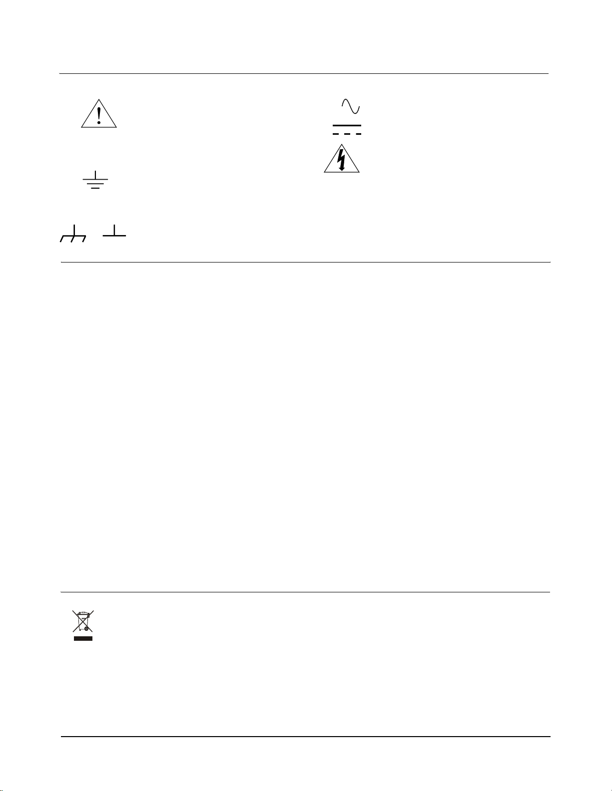
Setting the Logical
Address Switch
Follow the next figure and ignore any switch numbering printed on the
Logical Address switch. When installing more than one VT1422A in a
single VXIbus Mainframe, set each instrument to a different Logical
Address.
Setting the Logical Address Switch
Default Switch Setting
Logical Address = 208
1
24 Getting Started Chapter 1
Page 25
Installing Signal
Conditioning
Plug-Ons
The following illustrations show the steps used to install Signal
Conditioning Plug-ons (SCPs). Before installing an SCPs, reading the
"Separating Digital and Analog SCP Signals" in Appendix E page 483 is
recommended.
Caution Use approved Static Discharge Safe handling procedures
anytime the covers are removed from the VT1422A or when
handling the SCPs.
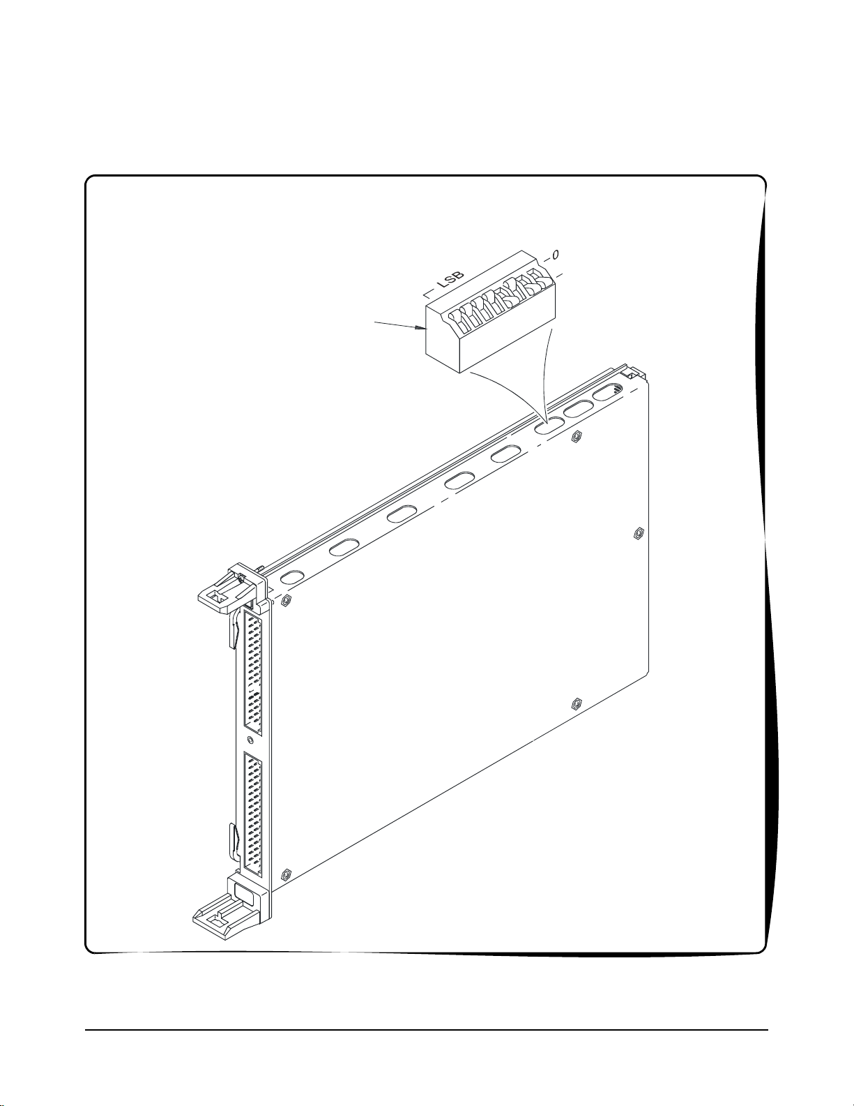
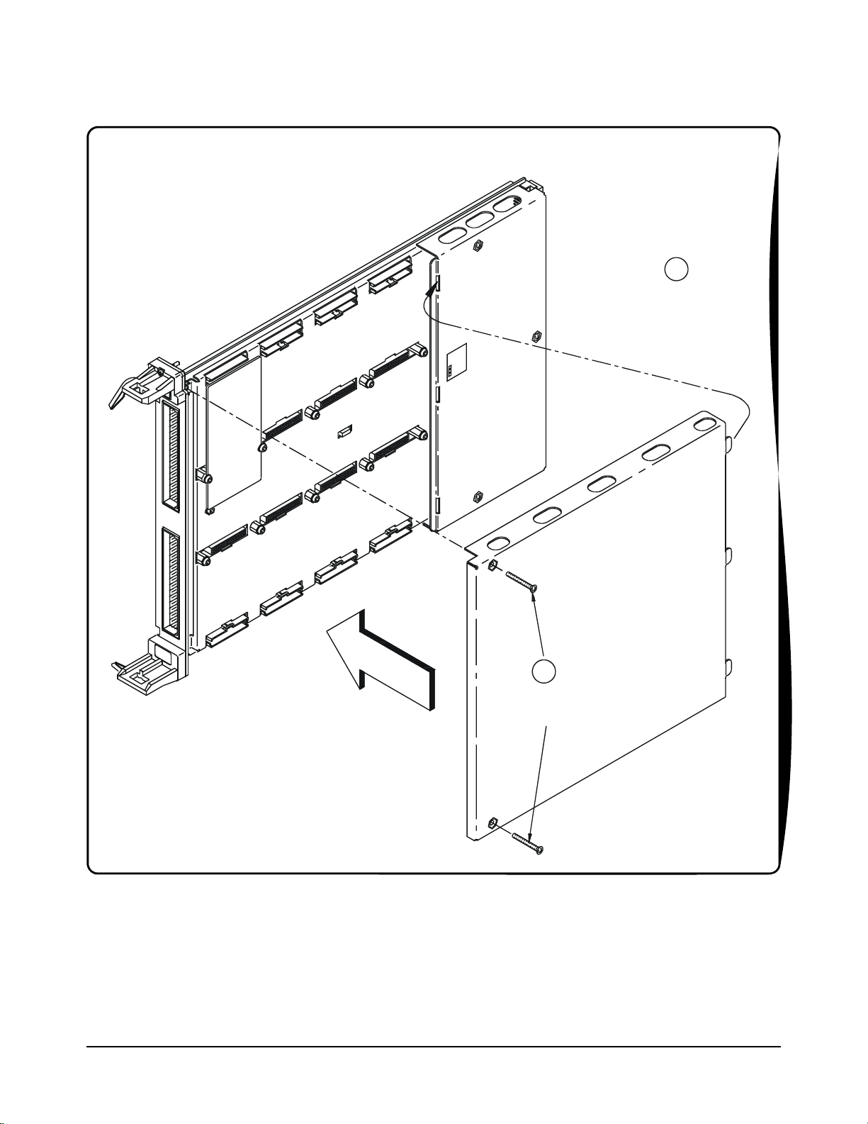
Installing SCPs: Step 1, Removing the Cover VT1422A
2
Remove the SCP
Retaining Screws
1
Remove2screws(#10Torx);
lift front and slide out tabs
Getting Started 25Chapter 1
Page 26
p
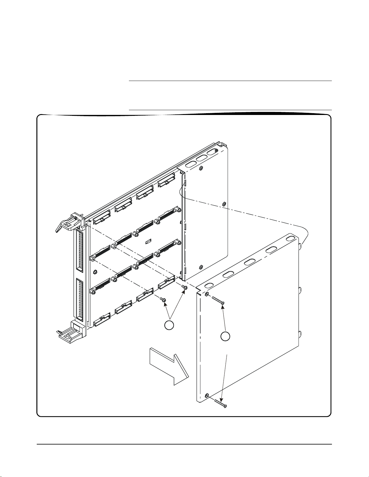
Installing SCPs: Step 2, Mounting an SCP
CAUTION
Use approved Static
Discharge handling
procedures when handling the
VT1422A Multifunction DAC
Modules and the SCPs
1
Align the SCP
connectors with the
Module connectors
and then
ush in
SCP
2
Tighten the SCP
Retaining Screws
26 Getting Started Chapter 1
Page 27
Installing SCPs: Step 3, Reinstalling the Cover VT1422A
1
Line up the 3 Tabs
with the 3 Slots;
then lower cover
onto the Module
2
Tighten
2Screws
Getting Started 27Chapter 1
Page 28
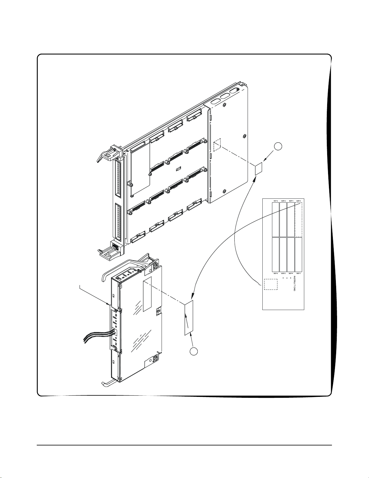
Installing SCPs: Step 4, Labeling
Peel off correct
Label from Card and
Stick on the
appropriate place on
the Cover
1
Terminal Module
(Connect t o A/D
Module Later)
S1
Stick-on Label furnished with the SCP
(Part Number: 43-0133-xxx)
2
Peel off Label from
Card and Stick on
the Terminal
Moduletobe
Connected to the
A/D Mo dule
28 Getting Started Chapter 1
Page 29

Disabling the
Input Protect
Feature
(Optional)
Voids Warranty! Disabling the Input Protection Feature voids the VT1422A's warranty.
Disabling the Input Protect feature voids the VT1422A's warranty. The Input
Protect feature allows the VT1422A to open all channel input relays if any input's
voltage exceeds ±19 volts (±6 volts for digital I/O SCPs). This feature will help to
protect the card's Signal Conditioning Plug-ons, input multiplexer, ranging
amplifier and A/D from destructive voltage levels. The level that trips the protection
function has been set to provide a high probability of protection. The voltage level
that is certain to cause damage is somewhat higher. If, in an application, the
importance of completing a measurement run outweighs the added risk of
damage to the VT1422A, the input protect feature may be disabled.
To disable the Input Protection feature, locate and cut JM2202. Make a single cut in
the jumper and bend the adjacent ends apart. See following illustration for location
of JM2202.
Disabling
Flash Memory
Access
(Optional)
The Flash Memory Protect Jumper (JM2201) is shipped in the “PROG” position. It
is recommended that the jumper be left in this position so that all of the calibration
commands can function. Changing the jumper to the protect position prevents the
following from being executed:
•The SCPI calibration command CAL:STORE ADC | TARE
•The register-based calibration commands STORECAL and STORETAR
•Any application that installs firmware-updates or makes any other
modification to Flash Memory through the A24 window.
With the jumper in the “PROG” position, one or more VT1422As can be completely
calibrated without removing them from the application system. A VT1422A
calibrated in its working environment will, in general, be better calibrated than if it
were calibrated separate from its application system.
The multimeter used during the periodic calibration cycle should be considered the
calibration transfer standard. Allow Calibration Organization control unauthorized
access to the calibration constants.
If access must be limited to the VT1422A's calibration constants, place JM2201 in
the protected position and cover the shield retaining screws with calibration
stickers. See the following illustration for location of JM2201.
Getting Started 29Chapter 1
Page 30
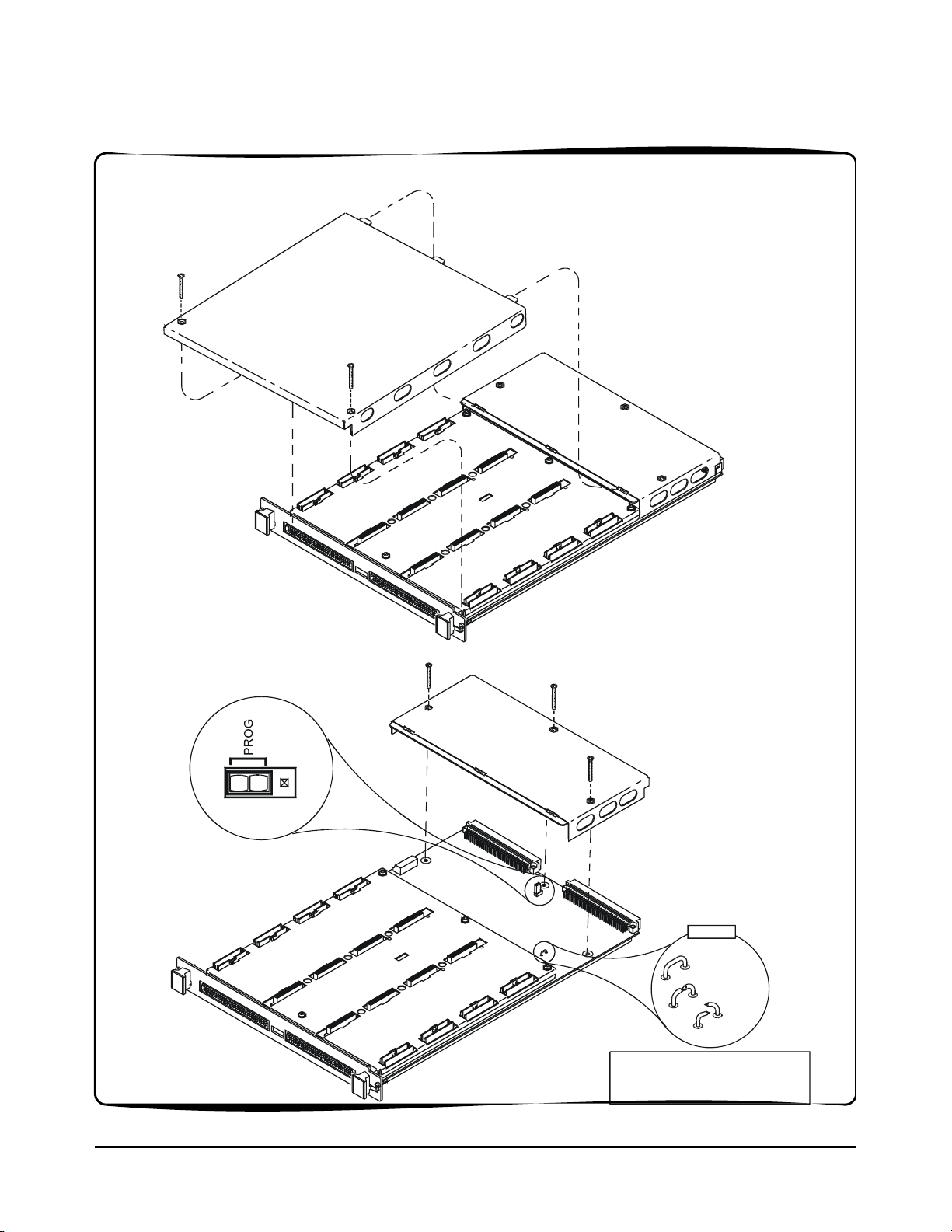
Accessing and Locating JM2201 and JM2202 VT1422A
Flash Memory Protect Jumper
Default = PROG
(recommended)
JM2201
JM2202
1 Locate
2Cut
3 Bend
Input Protect Jumper
Warning: Cutting this Jumper
VoidsYour Warranty!
30 Getting Started Chapter 1
Page 31

Installing the Module
Installation of the VT1422A VXI module is covered in the mainframe manual.
WARNING All instruments within the VXI mainframe are grounded through
the mainframe chassis. During installation, tighten the
instrument's retaining screws to secure the instrument to
the mainframe and to make the ground connection.
WARNING SHOCK HAZARD. Only qualified, service-trained personnel who
are aware of the hazards involved should install, configure, or
remove the VXI Module. Disconnect all power sources from the
mainframe, the Terminal Modules and installed modules before
installing or removing a module.
Instrument Drivers
Two driver types are supplied on the VXIplug&play Drivers & Product Manuals
CD that comes with the VT1422A. There is a VXIplug&play driver which includes
a front panel program and help file. In addition, there is also a downloadable driver
for the Agilent/HP E1406A Command Module. View the readme.txt file provided
with the VXIplug&play driver for possible update information.
About Example Programs
Examples on CD All example programs mentioned by file name in this manual are available on the
VXIplug&play Drivers & Product Manuals CD supplied with the VT1422A. Again,
see the readme.txt file for the specific file locations of these examples.
Example
Command
Sequences
Typical Example
program
Where programming concepts are discussed in this manual, the commands to send
to the VT1422A are shown in the form of command sequences. These are not
example programs because they are not written in any computer language. They are
meant to show the VT1422A SCPI commands in the sequence they should be sent.
Where necessary these sequences include comments to describe program flow and
control such as loop - end loop and if - end if. See “Example SCPI Command
Sequence” on page 139. for an example. For VXIplug&play users, there is an
“Example VXIplug&play Driver Function Sequence” on page 140.
The Verify program (file name verif.cpp) is printed below to show a typical
VXIplug&play program for the VT1422A.
Getting Started 31Chapter 1
Page 32

Verifying a Successful Configuration
An example C program source is shown on the following pages. This program is
included on the VXI Technology VXIplug&play Drivers & Product Manuals CD
that comes with the VT1422A (file name verif.cpp). The program uses the *IDN?
query command to verify the VT1422A is operational and responding to
commands. The program also has an error checking function (check()). It is
important to include an instrument error checking routine in the programs created,
particularly the initial trial programs, so that instant feedback can be attained while
learning about the VT1422A. Compile this program acc ording to the plug&play help
file (hpe1422.hlp) topics "Introduction to Programming"
Programs Using Integrated Environments."
/*******************************************************************************
verif.cpp
This example program verifies your instrument installation by reading the
instrument IDs and then querying for and printing the SCP types found.
Use the "Copy Button" in the Help File's "Example" window to place this code
into the clipboard, then paste this code text into your development tool's
editor window. Similarly, "Copy" the actual example code from the help file's
"Example" window and paste it into the location provided below.
link with the hpe1422_32.lib - library file
→ "Compiling and Linking
*******************************************************************************
*/
#include <stdio.h>
#include <stdlib.h>
#include <string.h>
#include <hpe1422.h> /* include the driver header file */
/* GPIB-VXI addressing (0 is the interface number, 208 is the */
/* instrument logical address, INSTR is a VISA resource type) */
#define INSTR_ADDRESS "GPIB-VXI0::208::INSTR"
ViSession addr;
ViStatus errStatus;
/* Function Prototypes */
void main (void); /* Main function */
void rst_inst(void); /* Resets the instrument and sends a device clear */
void reads_instrument_id(void); /* reads instrument software revision */
void check (ViSession addr, ViStatus errStatus); /* checks module errors */
/*******************************************************************************/
void main (void) /* Main function */
{
ViChar err_message[256];
/* open device session and reset the instrument; check if successful */
errStatus = hpe1422_init(INSTR_ADDRESS,0,0,&addr);
if( VI_SUCCESS > errStatus)
{
hpe1422_error_message( addr, errStatus, err_message);
printf("Unable to open %s\n", INSTR_ADDRESS);
printf("hpe1422_init() returned error message %s\n", err_message);
32 Getting Started Chapter 1
Page 33

return;
}
rst_inst(); /* Resets the instrument and sends a device clear */
reads_instrument_id(); /* Reads instrument software revision */
/* close the device session */
hpe1422_close(addr);
}
/****************************************************************************/
void rst_inst(void)
/* Function to set the interface timeout period, resets the instrument, */
/* waits for completion of reset and sends a device clear to enable */
/* the instrument to receive a new command */
{
ViInt32 result;
/* set timeout to allow completion of reset */
errStatus = hpe1422_timeOut(addr, 5000);
check(addr, errStatus);
/* reset the instrument */
errStatus = hpe1422_reset(addr);
check(addr, errStatus);
/* wait for completion of *RST */
errStatus = hpe1422_cmdInt32_Q(addr,"*OPC?",&result);
check(addr, errStatus);
/* send a device clear to enable new commands to be sent to the instrument */
errStatus = hpe1422_dcl(addr);
check(addr, errStatus);
/* enables automatic error checking after each driver call */
errStatus = hpe1422_errorQueryDetect( addr, VI_TRUE);
}
/****************************************************************************/
void reads_instrument_id(void)
/* Function uses a hpe1422__revision_query to read the software revision */
/* string. */
{
ViChar driver_rev[256];
ViChar instr_rev[256];
/* Query the instrument for its firmware revision */
errStatus = hpe1422_revision_query(addr, driver_rev, instr_rev);
/* Print the results */
printf("The instrument driver's revision is %s\n", driver_rev);
printf("The instrument's firmware revision is %s\n", instr_rev);
}
/****************************************************************************/
/****************************************************************************/
/* error checking routine */
void check (ViSession addr, ViStatus errStatus)
{
ViInt32 err_code;
ViChar err_message[256];
Getting Started 33Chapter 1
Page 34

if(VI_SUCCESS > errStatus)
{
hpe1422_dcl(addr); /* send a device clear */
if(hpe1422_INSTR_ERROR_DETECTED == errStatus)
{
/* read instrument error until error queue is empty*/
do
{
hpe1422_error_query( addr, &err_code, err_message);
if(err_code != 0) printf("Instrument Error : %ld, %s\n", err_code,
err_message);
}
while(err_code != 0);
}
else
{
/* query the instrument */
hpe1422_error_message( addr, errStatus, err_message);
/* display the error */
printf("Driver Error : %ld, %s\n", errStatus, err_message);
}
}
return;
}
34 Getting Started Chapter 1
Page 35

About This Chapter
This chapter shows how to plan and connect field wiring to the VT1422A's
Terminal Module. The chapter explains proper connection of analog signals
to the VT1422A, both two-wire voltage type and four-wire resistance type
measurements. Connections for other measurement types (e.g. strain using
the Bridge Completion SCPs) refer to the specific SCP manual. Chapter
contents include:
Chapter 2
Field Wiring
• Planning the Wiring Layout . . . . . . . . . . . . . . . . . . . . . . . . . . page 35
• Faceplate Connector Pin-Signal Lists. . . . . . . . . . . . . . . . . . . page 39
• Optional Terminal and Connector Modules . . . . . . . . . . . . . . page 40
• Reference Temperature Sensing with the VT1422A . . . . . . . page 44
• Preferred Measurement Connections . . . . . . . . . . . . . . . . . . . page 46
• Connecting the On-Board Thermistor. . . . . . . . . . . . . . . . . . . page 49
• Wiring and Attaching the Terminal Module. . . . . . . . . . . . . . page 50
• Removing the VT1422A Terminal Modules. . . . . . . . . . . . . . page 52
• Attaching and Removing the VT1422A RJ-45 Module . . . . . page 53
• Adding Components to the Terminal Module. . . . . . . . . . . . . page 54
• Spring and Screw Terminal Module Wiring Maps. . . . . . . . . page 55
Planning the Wiring Layout
The first point to understand is that the VT1422A makes no assumptions
about the relationship between Signal Conditioning Plug-on (SCP) function
and the position in the VT1422A that it can occupy. Any type of SCP can be
placed into any SCP position. There are, however, some factors which should
be considered when planning what mix of SCPs should be installed in each
of the VT1422As. The following discussions will help explain and clarify
these factors.
SCP Positions and
Channel Numbers
The VT1422A has a fixed relationship between Signal Conditioning Plug-on
positions and the channels they connect to. Each of the eight SCP positions
can connect to eight channels. Figure 2-1 shows the channel number to SCP
relationship.
Field Wiring 35Chapter 2
Page 36

SCP
Position 0
(on-board addresses 00-07)
SCP
Position 1
(on-board addresses 08-15)
Terminal
Module
Note: Each channel line represents
Both a Hi and Lo signal line.
Range Amp
16-Bits
A/D
Converter
SCP
Position 2
(on-board addresses 16-23)
SCP
Position 3
(on-board addresses 24-31)
SCP
Position 4
(on-board addresses 32-39)
SCP
Position 5
(on-board addresses 40-47)
Terminal Module
SCP
(on-board addresses 48-55)
(on-board addresses 56-63)
Position 6
SCP
Position 7
Figure 2-1. Channel Numbers at SCP Positions
36 Field Wiring Chapter 2
Page 37

Sense SCPs and
Output SCPs
Some SCPs provide input signal conditioning (sense SCPs such as filters
and amplifiers) while others provide stimulus to the measurement circuit
(output SCPs such as current sources and strain bridge completion).
In general, channels at output SCP positions are not used for external signal
sensing but are paired with channels of a sense SCP. Two points to remember
about mixing output and sense SCPs:
1. Paired SCPs (an output and a sense SCP) may reside in separate
VT1422As. SCP outputs are adjusted by *CAL? to be within a
specific limit. The Engineering Unit (EU) conversion used for a sense
channel will assume the calibrated value for the output channel.
2. Output SCPs, while providing stimulus to the measurement circuit,
reduce the number of external sense channels available to the VT1422A.
Figure 2-2 illustrates an example of "pairing" output SCP channels with sense
SCP channels (in this example, four-wire resistance measurements).
sense Hi
Note
Each channel line
represents both a
Hi and Lo input
Input Multiplexer
SCP
3
(sense)
SCP
4
(output)
Terminal Module
sense Lo
Ch 24
Ch 31
Ch 32
Ch 39
Figure 2-2. Pairing Output and Sense SCP Channels
output Lo
output Hi
Field Wiring 37Chapter 2
Page 38

Planning for
Thermocouple
Measurements
Note The isothermal reference temperature measurement made by a VT1422A
Note T o make good low-noise measurements, shielded wiring must be used from
Using either the Screw Terminal or Spring Terminal Modules,
thermocouples and the thermocouple reference temperature sensor can be
wired to any of the VT1422A's channels. When the scan list is executed, one
must ensure that the reference temperature sensor is specified in the channel
sequence before any of the associated thermocouple channels.
External wiring and connections to the VT1422A are made using Terminal
Modules (see Figures 2-4 through 2-6).
applies only to thermocouple measurements made by that instrument.
In systems with multiple VT1422As, each instrument must make its own
reference measurements. The reference measurement made by one
VT1422A cannot be used to compensate thermocouple measurements
made by another VT1422A.
the device under test to the Terminal Module at the VT1422A. The shield
must be continuous through any wiring panels or isothermal reference
connector blocks and must be grounded at a single point to prevent ground
loops. See "Preferred Measurement Connections" later in this section and
“Wiring and Noise Reduction Methods” on page 483.
38 Field Wiring Chapter 2
Page 39

Faceplate Connector Pin-Signal Lists
Figure 2-3 shows the Faceplate Connector Pin Signal List for the VT1422A.
Count
From
Top
1
GND
2
GND
3
GND
4
GND
5
REMOTE CHANNEL MULTI-FUNCTION DAC MODULE
H
L
V
CAL
G
BUS
H
L
G
GND
6
G0
7
G1
8
H08
9
L08
10
H11
11
L11
12
H14
13
L14
14
H17
15
L17
16
H20
17
L20
18
H23
19
L23
20
G2
21
H27
22
L27
23
H30
24
L30
25
G3
26
G3
27
GND
28
GND
29
GND
30
GND
31
GND
32
GND
1
HCAL
2
LCAL
3
GND
4
HOHM
5
LOHM
6
GND
H00
H01
H02
H03
H04
H05
H06
H07
H09
H10
H12
H13
H15
H16
H18
H19
H21
H22
H24
H25
H26
H28
H29
H31
G3
G3
GND
HOHM
HCAL
GND
H_I
GND
HCAL
LCAL
GND
HOHM
LOHM
GND
L00
L01
L02
L03
L04
L05
L06
L07
L09
L10
L12
L13
L15
L16
L18
L19
L21
L22
L24
L25
L26
L28
L29
L31
G3
G3
GND
LOHM
LCAL
GND
L_I
GND
Count
From
Bottom
6
5
4
3
2
1
32
31
30
29
28
27
26
25
24
23
22
21
20
19
18
17
16
15
14
13
12
11
10
9
8
7
6
5
4
3
2
1
1
GND
GND
VT1422A
2
GND
3
GND
4
TST-A
5
GND
6
G4
7
G4
8
G4
9
L33
10
H33
11
L36
12
H36
13
G5
14
L40
15
H40
16
L43
17
H43
18
L46
19
H46
20
L49
21
H49
22
L52
23
H52
24
L55
25
H55
26
G6
27
G7
28
GND
29
GND
30
GND
31
GND
32
GND
TRG
GND
SYSF
GND
G4
G4
G4
H32
H34
H35
H37
H38
H39
H41
H42
H44
H45
H47
H48
H50
H51
H53
H54
H56
H57
H58
H59
H60
H61
H62
H63
GND
GND
GND
GND
GND
G4
G4
G4
L32
L34
L35
L37
L38
L39
L41
L42
L44
L45
L47
L48
L50
L51
L53
L54
L56
L57
L58
L59
L60
L61
L62
L63
32
31
30
29
28
27
26
25
24
23
22
21
20
19
18
17
16
15
14
13
12
11
10
9
8
7
6
5
4
3
2
1
Figure 2-3. VT1422A Faceplate Connector Pin Signals
Field Wiring 39Chapter 2
Page 40

Optional Terminal and Connector Modules
The VT1422A is comprised of the main A/D module and optionally, a
Connector or Terminal Module. The Option 001 Connector Module provides
sixteen RJ-45 jacks to allow easy connection of the VT1422A to Remote
Signal Conditioning Units (RSCUs) like the VT1529A/B Remote Strain
Conditioning Unit. Optional conventional terminal modules include a
Terminal Module with screw-clamped terminal blocks (Option 011) and
another with spring-clamped terminal blocks (Option 013).
The Spring Terminal Module and Screw Terminal Module provide:
•Terminal connections to field wiring.
-- Allows a mix of direct field wiring with some connections to
Remote Signal Conditioning Units
•Strain relief for the wiring bundle.
•Reference junction temperature sensing for thermocouple
measurements.
•Ground-to-Guard connections for each channel.
The RJ-45 Connector Module provides:
•Easy mass terminated plug-in connection to Remote Signal
Conditioning Units.
The SCPs and
Terminal Module
Terminal Module
Layout
WARNING When handling user wiring connected to the Terminal Module,
•Allows some direct analog or digital field wiring to be connected to
RJ-45 modular plugs that are then plugged into the Connector Module.
•Note: Since the RJ-45 Connector Module was designed for connection
to RSCUs, it doesn’t provide an on-board isothermal reference
thermistor or connection to the VT1422A’s on-board current source.
This means that the RJ-45 Terminal Module is not suitable for direct
connection to thermocouples.
Each SCP includes a set of labels to map that SCP's channels to the Terminal
Module's terminal blocks. See “Installing SCPs: Step 4, Labeling” on
page 28
Figures 2-4 through 2-6 show the layout and feature location of the Terminal
Modules available for the VT1422A.
consider the highest voltage present accessible on any
terminal. Use only wire with an insulation rating greater than
the highest voltage which will be present on the Terminal
Module. Do not touch any circuit element connected to the
Terminal Module if any other connector to the Terminal Module
is energized to more than 30 V ac rms or 60 V dc.
40 Field Wiring Chapter 2
Page 41

The RJ-45
Connector Module
RJ-45 Connector Module Pinout
for Std SCP I/O
Ch2
Ch0
Shield G nd
RJ-45 Connector Module Pinout
for Std SCP I/O
Ch3
Ch1
Shield G nd
(even chs 0,2,4,6)
Ch4
+
+
12345678
(odd chs 1,3,5,7)
Ch5
+
+
12345678
-
Ch2
Ch6
Shield Gnd
-
Ch3
Ch7
Shield Gnd
Figure 2-4 shows the VT1422A Option 001 RJ-45 Connector Module with
connector pin numbering.
+=Hi
-=Lo
+=Hi
-=Lo
!
0
1
8
R
e
l
e
a
9
s
e
1
6
1
7
R
2
e
4
a
d
M
a
n
2
u
5
a
l
f
o
r
R
e
3
l
2
e
a
s
e
I
n
s
3
t
3
r
u
c
t
i
o
n
s
4
0
4
1
R
4
e
8
l
e
a
s
e
4
9
5
6
5
7
SCP position 0, chs 0-6 and 1-7
SCP position 1, chs 8-14 and 9-15
SCP position 2, chs 16-22 and 17-23
SCP position 3, chs 24-30 and 25-31
SCP position 4, chs 32-38 and 33-39
SCP position 5, chs 40-46 and 41-47
SCP position 6, chs 48-54 and 49-55
SCP position 7, chs 56-62 and 67-63
Figure 2-4. RJ-45 Connector Module and Pin-out
Spring Terminal
Module Layout
Caution WIRING THE TERMINAL MODULES. When wiring to the
Figure 2-5 shows the VT1422A Option 013 Spring Terminal Module
features and jumper locations.
terminal connectors on the screw clamp and spring clamp
Terminal Module, be sure not to exceed a 5 mm strip back of
insulation to prevent the possibility of shorting to other wiring
on adjacent terminals.
Field Wiring 41Chapter 2
Page 42

Sockets for Guard to
Ground Connections
HL
HL
08
00 01
G
G
HL
HL
09
G
G
HL
HL
02 03
10
G
G
HL
HL
11
G
G
HL
HL
04
12
G
G
HL
HL
05
13
G
G
HL
HL
06
14
G
G
HL
HL
07
15
G
01
00
ON
BOARD
Terminal B loc k for
Input Connections
Jumper to select for
On-board or Remote
Temperature Sensing
HCAL
LOHM
HDHM
On-board Thermistor
for Temperature Se nsi ng
J1
REM
GND GND
LTS
HTS
LTI
HTI
GND
TRIG
GND
LCAL
TerminalBlock with
Remote Temperature Se nsing,
Trigger, and ot her Connecti ons
Figure 2-5. VT1422A Spring Terminal Module
42 Field Wiring Chapter 2
Page 43

Screw Terminal
Module Layout
On-Board Reference
Temperature Sensing
RT1
Figure 2-6 shows the VT1422A Option 011 Screw Terminal Module
features and jumper locations.
JM1
ON BOARD
REM
RT1
Jumper Detail
JM1
ON BOARD
REM
Remote Reference
Temperature Sensing
Figure 2-6. VT1422A Screw Terminal Module
Field Wiring 43Chapter 2
Page 44

Reference Temperature Sensing with the VT1422A
The Screw Terminal and Spring Terminal Modules provide an on-board thermistor
for sensing isothermal reference temperature of the terminal blocks. Also provided
is a jumper set (J1 in Figures 2-7 and 2-8) to route the VT1422A's on-board current
source to a thermistor or RTD on a remote isothermal reference block. Figure 2-7
and Figure 2-8 show connections for both local and remote sensing. See “Connecting
the On-Board Thermistor” on page 49 for location of J1.
VT1422A
On-Board
Current Source
VT1422A
Terminal Module
ON
REM
BOARD
J1
Any Sense
Channel
Figure 2-7. On-Board Thermistor Connection
Terminal Module
Field Wiring
HTI
LTI
HTS
LTS
Hnn
Lnn
Field Wiring
HTI
On-Board
Current Source
REM
J1
Any Sense
Channel
ON
BOARD
LTI
HTS
LTS
Hnn
Lnn
Figure 2-8. Remote Thermistor or RTD Connections
44 Field Wiring Chapter 2
Page 45

Terminal Module
Considerations for
TC Measurements
The isothermal characteristics of the VT1422A Terminal Module are crucial for
good TC readings and can be affected by any of the following factors:
1. The clear plastic cover must be on the Terminal Module.
2. The thin white mylar thermal barrier must be inserted over the Terminal
Module connector. This prevents airflow from the VT1422A A/D Module
into the Terminal Module.
3. The Terminal Module must also be in a fairly stable temperature environment
and it is best to minimize the temperature gradient between the VT1422A
module and the Terminal Module.
4. The VXI mainframe cooling fan filters must be clean and there should be as
much clear space in front of the fan intakes as possible.
5. Recirculating warm air inside a closed rack cabinet can cause a problem if
the Terminal Module is suspended into ambient air that is significantly
warmer or cooler. If the mainframe recess is mounted in a rack with both
front and rear doors, closing both doors helps keep the entire VT1422A at a
uniform temperature. If there is no front door, try opening the back door.
6. VXI Technology recommends that the cooling fan switch on the back of the
of the CT-400 Mainframe be in the "High" position. The normal variable
speed cooling fan control can make the internal VT1422A module
temperature cycle up and down, which affects the amplifiers with these
microvolt-level signals.
Field Wiring 45Chapter 2
Page 46

Preferred Measurement Connections
For any A/D Module to scan channels at high speeds, it must use a very short sample
μ
IMPORTANT!
Notes 1. Try to install Analog SCPs relative to Digital I/O as shown in "Separating
period (< 10
its inputs, that noise will be part of the measurement. To make quiet, accurate
measurements in electrically noisy environments, use properly connected shielded
wiring between the A/D and the device under test. Figure 2-9 shows recommended
connections for powered transducers, thermocouples, and resistance transducers.
(See Appendix E page 483 for more information on Wiring Techniques.)
Digital and Analog Signals" in Appendix E.
2. Use individually shielded, twisted-pair wiring for each channel.
3. Connect the shield of each wiring pair to the corresponding Guard (G)
terminal on the Terminal Module (see Figure 2-10 for schematic of Guard to
Ground circuitry on the Terminal Module).
4. The Terminal Module is shipped with the Ground-to-Guard (GND-GRD)
shorting jumper installed for each channel. These may be left installed or
removed (see Figure 2-11 to remove the jumper), dependent on the following
conditions:
a. Grounded Transducer with shield connected to ground at
b. Floating Transducer with shield connected to the transducer at
5. In general, the GND-GRD jumper can be left in place unless it is necessary to
remove to break low frequency (below 1 kHz) ground loops.
6. Use good quality foil or braided shield signal cable.
7. Route signal leads as far as possible from the sources of greatest noise.
8. In general, don't connect Hi or Lo to Guard or Ground at the VT1422A.
9. It is best if there is a dc path somewhere in the system from Hi or Lo to
Guard/Ground.
10.The impedance from Hi to Guard/Ground should be the same as from Lo to
Guard/Ground (balanced).
11. Since each system is different, don't be afraid to experiment using the
suggestions presented here until an acceptable noise level is found.
s for the VT1422A). If significant normal mode noise is presented to
the transducer: Low frequency ground loops (dc and/or 50/60 Hz)
can result if the shield is also grounded at the Terminal Module end.
To prevent this, remove the GND-GRD jumper for that channel
(Figure 2-9 A/C).
the source: In this case, the best performance will most likely be
achieved by leaving the GND-GRD jumper in place (Figure 2-9 B/D).
46 Field Wiring Chapter 2
Page 47

Device
+
Under Test
pressure
P
to
V
power
Shield
Hi
Lo
Device
Under Test
Device
Under Test
Device
Under Test
pressure
- power
+ power
P
to
V
- power
Shield
Example for
Thermocouples
Shield
Example for
Powered
Transducers
Shield
Example for
Powered
Transducers
C
A
B
Hi
Lo
Guard
Hi
Lo
Guard
Hi
Lo
Guard
Remove Jumper to
break Ground Loop
(shield connected to
ground at transducer)
Remove Jumper to
break Ground Loop
(shield connected to
ground at transducer)
Leave Jumper
in Place
(transducer floating)
Shield
Example for
Resistive
Transducers
D
E
Guard
Hi
Lo
Guard
Current Hi ( + )
Current Lo ( – )
Figure 2-9. Preferred Signal Connections
Leave Jumper
in Place
(transducer floating)
Jumper may be left in
place as Current Lo (+)
is at VT1422A GND Potential
Field Wiring 47Chapter 2
Page 48

External Connections
SC
For each
SCP Position
G0
G7
Terminal Module
0.1 Fµ
1 k
Ω
GND to GRD Jumper
(removable)
1 k
Ω
P
10 k
Ω
0.1 Fµ
GND to GRD Jumper
(removable)
Figure 2-10. GRD/GND Circuitry on Terminal Module
Remov ing G uard to
Ground on Channel 00
10 k
Ω
Figure 2-11. Grounding the Guard Terminals
48 Field Wiring Chapter 2
Page 49

Connecting the On-Board Thermistor
r
The following figures show how to use the VT1422A to make temperature
measurements using the on-board Thermistor or a remote reference sensor.
The Thermistor is used for reference junction temperature sensing for thermocouple
measurements. Figure 2-12 shows the configuration for the VT1422A’s Spring
Terminal Module, Figure 2-6 shows the configuration for the Screw Terminal
Module. See “Reference Temperature Sensing with the VT1422A” on page 44 for
a schematic diagram of the reference connections.
ON
BOARD
J1
UnderCove
r
ON BOARD
PlacebothJ1jumpershereto
connect current so urce to
on-board thermistor RT1. Sense
RT1 by connecting any sense
channels to terminalsHTS and
LTS.
REM
ON
BOARD
J1
REM
REMote
Place both J1jumpers here to
route curre nt source to terminals
HTI and LTI. Connect these
terminals to remote thermistor o
RTD.Sense with any sense
channel.
J1
ON
BOARD
SCP 0
SCP 1
REM
SCP 7
SCP 2
SCP 3
SCP 5 SCP 6
SCP 4
See Figure 2-13 on page 50 to remove the cover
Figure 2-12. Temperature Sensing for the Terminal Module
Field Wiring 49Chapter 2
Page 50

Wiring and Attaching the Terminal Module
Figures 2-13 and 2-14 show how to open, wire and attach the terminal module to a
VT1422A.
1
Remove Clear Cover.
A. Release screws.
B. Press tab forward
and release.
Tab
Make Connections (Spring Clamp)
3
Depress terminal lever(s). Insert
wire(s) into terminal(s). Release levers.
Use wire size 20-26 AWG
5 mm
0.2"
Special tool P/N 8710-2127
(Shipped with Terminal Module)
2
Remove and Retain Wiring Exit Panel
(Screw Ty pe)
Remove 1 of the 3
wire exit panels.
Use wire
size 16-26
AWG
5 mm
0.2"
VW1 Flammability
Rating
Insert wire into terminal.
Tighten screw.
Route Wiring
4
Tighten wraps to
secure wires.
Figure 2-13. Opening and Wiring the VT1422A’s Terminal Module
50 Field Wiring Chapter 2
Page 51

Replace Wiring Exit Panel
5
Replace Clear Co ver
6
A. Hook in the top cover tabs
onto the fixture
B. Press down and
tighten screws
Cut required
holes in panels
for wire exit
Install the Terminal
7
Module
Install Mylar Thermal Barrier
on Terminal Module
connectors
Keep wiring exit panel
hole as small as
possible
Push in the Extraction Levers to Lock the
8
Terminal Module onto the VT1422A
Extraction
Levers
VT1422A
Module
Figure 2-14. Closing and Attaching the VT1422A Terminal Module
Field Wiring 51Chapter 2
Page 52

Removing the VT1422A Terminal Modules
Figure 2-15 shows how to remove the Spring Terminal and Screw Terminal Modules
from the VT1422A.
Releasethetwoextraction
1
levers and push both levers
out simultaneo usly
Extraction Lever
Use a small screwdriver
to pry and release the
twoextractionlevers
Free and remove the Terminal
2
Module from the A/D Module
Extraction Lever
VT1422A
Extraction Lever
Figure 2-15. Removing the Screw and Spring Terminal Modules
52 Field Wiring Chapter 2
Page 53

Attaching and Removing the VT1422A RJ-45 Module
Figure 2-16 shows how to remove the RJ-45 Terminal Module.
1
Install on VT1422A
2
Push in the Extraction Levers to Lock
the Terminal Module onto the VT1422A
Extraction
Levers
3
Releasing the Extraction Levers to Remove the Terminal Module
Screwdriver
With 1/8"
Blade
Figure 2-16. Removing the RJ-45 Terminal Module
Field Wiring 53Chapter 2
Page 54

Adding Components to the Terminal Module
The back of the terminal module PCB (printed circuit board) provides surface mount
pads which can be used to add serial and parallel components to any channel's signal
path. Figure 2-17 shows additional component locator information (see the
schematic and pad layout information on the back of the terminal module PCB).
Figure 2-18 shows some usage example schematics.
HI
TO USER WIRING
LO
Upper layout also applies here
Upper layout also applies here
Lower layout also applies here Lower layout also applies here
SCHEMATIC OF MODIFIABLE PARTS
HI HI
COMP
LOCATOR
SH
LO
SL
TO VT1413C/VT1415A
LO
LOCATOR
COMP
Figure 2-17. Additional Component Location
SH
0 ohms
SL
0 ohms
PHL
HI
TO VT1422A
LO
PH
PL
SH
HI
10 kohms
LO
10 kohms
0.1 Fµ
PHL
SL
PH
HI
TO VT1422A
LO
PL
Normal Mode Low-Pass Filter Circuit
±16 volts unless attenuated with a VT1513A SCP)
HI
TO USER WIRING
LO
Default Circuit
SH
PHL
0 ohms
SL
0 ohms
250 ohmsor200 ohms
HI
TO VT1422A
LO
PH
4-20 mA NOTE: input must not exceed common mode limits (usually
PL
4 to 20 mA Sense
5 V full scale with 250 ohm (must use 16 volt range)
4 V full scale with 200 ohm (can use 4 volt range for better resolution)
Figure 2-18. Series & Parallel Component Examples
54 Field Wiring Chapter 2
Page 55

Spring and Screw Terminal Module Wiring Maps
Figure 2-19 shows the Spring Terminal Module wiring map.
Top
All wiring entering Terminal
Module passes under this
strain relief bar
H24
L24
G24
H25
L25
G25
H26
L26
G26
H27
L27
G27
H28
L28
G28
H29
L29
G29
H30
L30
G30
H31
L31
G31
H16
L16
G16
H17
L17
G17
H18
L18
G18
H19
L19
G19
H20
L20
G20
H21
L21
G21
H22
L22
G22
H23
L23
G23
H08
L08
G08
H09
L09
G09
H10
L10
G10
H11
L11
G11
H12
L12
G12
H13
L13
G13
H14
L14
G14
H15
L15
G15
GND
GND
GND
GND
LTS
HTS
LTI
HTI
GND
TRIG
GND
LCAL
HCAL
LOHM
HOHM
GND
GND
GND
H00
L00
G00
H01
L01
G01
H02
L02
G02
H03
L03
G03
H04
L04
G04
H05
L05
G05
H06
L06
G06
H07
L07
G07
Heavy line indicates the
side of the terminal block
that the wire enters
Figure 2-19. Spring Terminal Module Full-Size Wring Map
G32
L32
H32
G33
L33
H33
G34
L34
H34
G35
L35
H35
G36
L36
H36
G37
L37
H37
G38
L38
H38
G39
L39
H39
G40
L40
H40
G41
L41
H41
G42
L42
H42
G43
L43
H43
G44
L44
H44
G45
L45
H45
G46
L46
H46
G47
L47
H47
G48
L48
H48
G49
L49
H49
G50
L50
H50
G51
L51
H51
G52
L52
H52
G53
L53
H53
G54
L54
H54
G55
L55
H55
G56
L56
H56
G57
L57
H57
G58
L58
H58
G59
L59
H59
G60
L60
H60
G61
L61
H61
G62
L62
H62
G63
L63
H63
Field Wiring 55Chapter 2
Page 56

Figure 2-20 shows the Screw Terminal Module wiring map.
heavy line indicates side of
terminal block wire enters
H08
L08
H09
L09
H10
L10
H24
L24
H25
L25
H26
L26
L37
H37
L38
H38
L39
H39
L53
H53
L54
H54
L55
H55
H11
L11
H12
L12
H13
L13
H27
L27
H28
L28
H29
L29
L34
H34
L35
H35
L36
H36
L50
H50
L51
H51
L52
H52
H14
H15
SCP 1
SCP 3
HOHM
LOHM
HCAL
LCAL
GND
TRG
HT1
HTS
SCP 4 SCP 6
H32
H33
H48
H49
L14
L15
G1
G1
H30
L30
H31
L31
G3
G3
LT1
LTS
G4
G4
L32
L33
G6
G6
L48
L49
H00
L00
H01
L01
H02
L02
H03
L03
H04
L04
H16
L16
H17
L17
H18
L18
H19
L19
L44
H44
L45
H45
L46
H46
L47
H47
L59
H59
L60
H60
L61
H61
L62
H62
L63
H63
H05
H06
SCP 0
L06
H07
H20
L20
H21
L21
H22
SCP 2
L22
H23
L23
SCP 5
H40
H41
H42
H43
SCP 7
H56
H57
H58
L05
L07
G0
G0
G2
G2
G5
G5
L40
L41
L42
L43
G7
G7
L56
L57
L58
Figure 2-20. Screw Terminal Module Full-Size Wiring Map
56 Field Wiring Chapter 2
Page 57

Field Wiring 57Chapter 2
Page 58

58 Field Wiring Chapter 2
Page 59

Chapter 3
Programming the VT1422A & VT1529A/B
for Remote Strain Measurement
About This Chapter
This chapter describes using the VT1422A in combination with the
VT1539A Remote Channel SCP and VT1529A/B Remote Strain
Conditioning Units to make large channel count strain measurements. The
system is shown being used strictly in a data acquisition mode where, after
configuration, it is driven by a user-defined channel list (the Scan List) and
sends the measurements to the unit’s FIFO buffer and Current Value Table
(CVT) for transfer to the computer. Of course, control algorithms can also
be created that execute concurrently with the Scan List driven data
acquisition operation. Chapter 4 and Chapter 6 cover general data
acquisition and control programming with algorithms. This chapter assumes
that the user is an expert when it comes to making strain measurements, so
this chapter simply illustrates how to make strain measurements with the
VXI Technology Remote Strain Measuring System (VT1422A, VT1539A,
and VT1529A/B). The chapter will cover:
• Instrument Setup for Remote Strain Measurements. . . . . . . . page 58
-- Preparing the VT1422A for Installation . . . . . . . . . . . . . . . page 58
-- Preparing the VT1529A/B for Use . . . . . . . . . . . . . . . . . . . page 59
-- Installing User Selected 1/4 Bridge Resistors (Optional). . page 59
-- Connecting VT1529A/Bs to the VT1422A. . . . . . . . . . . . . page 62
-- Connecting Excitation Supplies . . . . . . . . . . . . . . . . . . . . . page 67
• Connecting the VT1529A/B to Strain Gages . . . . . . . . . . . . . page 69
-- Channel Connector Pin-to-Signal Relationship . . . . . . . . . page 69
• VT1529A/B Bridge Configurations . . . . . . . . . . . . . . . . . . . . page 70
• Connecting to the VT1529A/Bs Dynamic Strain Ports . . . . . page 73
-- Dynamic Strain Port Offset Control . . . . . . . . . . . . . . . . . . page 75
• Remote Strain Channel Addressing . . . . . . . . . . . . . . . . . . . . page 76
-- Runtime Remote Scan Verification. . . . . . . . . . . . . . . . . . . page 76
• Programming for Remote Strain Measurement . . . . . . . . . . . page 78
-- Description of Strain Measurement . . . . . . . . . . . . . . . . . . page 78
Measure Strain Using Built-in Strain EU Conversion . . page 79
Measure Strain Using User Specified EU Conversion . . page 83
Measure Bridge Voltages and Convert to Strain. . . . . . . page 86
• Verifying Correct Bridge Completion (Shunt Cal) . . . . . . . . . page 90
• Built-in Strain Conversion Equations . . . . . . . . . . . . . . . . . . . page 92
Programming the VT1422A & VT1529A/B for Remote Strain Measurement 57Chapter 3
Page 60

Instrument Setup for Remote Strain Measurements
This section involves:
•Preparing the VT1422A for installation into a VXIbus Mainframe
•Preparing the VT1529A/B for use
•Connecting the VT1422A to VT1529A/B Remote Strain Completion
units.
•Connecting Excitation power supplies to the VT1529A/B
•Connecting strain bridges to the VT1529A/B
Preparing the
VT1422A for
Installation
The VT1422A requires VT1539A SCPs to control Remote Signal
Conditioning Units like the VT1529A/B Remote Strain Conditioning Unit.
Chapter 1 “Getting Started” covers everything which is needs to be done
before installing the VT1422A in its mainframe. This includes switch settings
and SCP installation. After performing the operations in Chapter 1, return
here for Remote Strain specific operations.
Overview Before getting into the specifics of configuring a Remote Strain Measuring
System, it might be helpful to see the overall set up. Figure 3-1 shows the
components and connections of a remote strain measuring system. The
circled letters identify connections that will be referenced in later sections.
Up to 4 excitation supplies
Each VT1422A with VT1539A SCPs
and VT1529A/B Remote Strain Units
can support up to 512 strain gages
VT1539A
SCP (Up to 8)
VT1529A/B
A
C
Up to 32 strain
B
gages
A
Up to 16 VT1529A/Bs
VT1529A/B
VT1422A Multifunction
DAC Module shown with
an Option 001 RJ-45
Connector Module
Up to four excitation supplies
Up to 32 strain
gages
Figure 3-1. Components of the Remote Strain Measuring System
58 Programming the VT1422A & VT1529A/B for Remote Strain Measurement Chapter 3
Page 61

Preparing the
VT1529A/B for Use
WARNING Ground the equipment: The safety Earth ground for the
WARNING The power cord is the only way to disconnect the VT1529A/B
For most applications, the VT1529A/B is ready for installation as delivered.
It is designed to be easily rack mounted in a system cabinet by its built-in
front panel extensions. All user connection are accessible on the front panel
with the exception of the line-cord jack which is on the rear of the unit.
The only pre-installation operation which may need to be considered is
installation of the user supplied quarter-bridge completion resistors. If these
are required by the application, see “Installing User Selected 1/4 Bridge
Resistors (Optional)” in the following section.
VT1529A/B is supplied through the ground conductor of the
power cable. Make sure that the installation’s ac line supply
connectors provide a suitable Earth ground.
from ac power. Therefore, the power cord must be accessible to
the operator at all times. When the VT1529A/B is mounted in a
system cabinet, the power cord need not be accessible since
the cabinet must have its own disconnect device.
Installing User
Selected 1/4 Bridge
Resistors (Optional)
Perform this operation only if one or more VT1529A/B channels are
required to provide 1/4 Bridge completion of other than 120
Only those with experience in soldering components on printed circuit
boards should attempt this installation. The VT1529A/B provides locations
on its printed circuit board for the user’s own 1/4 bridge completion
resistors. Bridge configuration commands then can switch these resistors
into the bridge completion circuits where the custom value resistors are
installed.
Ω or 350 Ω.
WARNING Keep away from live circuits: Operating personnel must not
remove equipment covers or shields. Procedures involving the
removal of covers or shields are for use by service-trained
personnel only. Under certain conditions, dangerous voltages
may exist even with the equipment switched off. To avoid
dangerous electrical shock, DO NOT perform procedures
involving cover or shield removal unless qualified to do so.
Removing the Top Cover Figure 3-2 shows how to access the printed circuit board where the user
specified resistors will be installed. Notice that both a surface-mount as well
as a through-hole position is provided for each channel.
Programming the VT1422A & VT1529A/B for Remote Strain Measurement 59Chapter 3
Page 62

Tab
2
Unlatch Cover from
Bottom Cover Tab
on Each Side
Detail "A"
Figure 3-2. Removing the VT1529A/B Top Cover
1
Loosen
Top Cover
Screw
3
Remove Top Cover
PC Board
See Detail "A"
60 Programming the VT1422A & VT1529A/B for Remote Strain Measurement Chapter 3
Page 63

Locating Resistors Figure 3-3 provides the relationship between P.C. board location and bridge
”
m
resistor channel number. The surface mount pads nearest the through-hole
locations are in parallel with them.
"Rxx" Indicates the
Channel Number
Through-Hole
R
R
E
E
S
S
U
U
-
-
0
1
0
0
OROR
R
R
Resistor Positions
R
R
R
E
E
S
S
U
U
-
1
0
0
0
R
R
R
E
E
S
S
U
U
-
3
2
0
0
R
R
R
R
E
E
S
S
U
U
-
7
6
1
1
R
R
R
E
S
U
4
2
R
R
E
S
U
5
2
R
Surface-Mount
R
R
R
E
E
S
S
U
U
-
5
4
0
0
R
R
R
E
E
S
S
U
U
-
-
6
7
0
0
R
R
R
R
E
E
S
S
U
U
-
1
0
2
2
R
R
R
R
E
E
S
S
U
U
-
9
8
2
2
R
R
Resistor Positions
R
R
R
E
E
S
S
U
U
-
9
8
0
0
R
P401
P402
3
0
4
P
R
R
R
E
E
S
S
U
U
-
3
2
1
1
R
R
R
E
E
S
S
U
U
-
-
0
1
1
1
R
R
R
R
E
E
S
S
U
U
-
-
4
5
1
1
R
R
R
R
E
E
S
S
U
U
-
9
8
1
1
R
R
R
R
E
E
S
S
U
U
-
3
2
2
2
R
R
R
R
E
E
S
S
U
U
-
7
6
2
2
R
R
R
R
E
E
S
S
U
U
-
1
0
3
3
R
R
Figure 3-3. Locating User 1/4 Bridge Resistor Positions
Installing Resistors Figure 3-4 shows a typical user selected 1/4 bridge resistor installation. Note
that resistor installations can be accomplished from the top of the board
without further disassembly. If installing through-hole resistors, be very
careful to observe the specified maximum safe resistor lead length to avoid
shorting the resistor to the chassis.
PC Board
Chassis
Programming the VT1422A & VT1529A/B for Remote Strain Measurement 61Chapter 3
0.1
2.54 m
Figure 3-4. Installing User 1/4 Bridge Resistors
Page 64

Connecting
VT1529A/Bs to the
VT1422A
The cable between a VT1422A and each VT1529A/B (connection "A" in
Figure 3-1) is a standard type of cable used in computer Local Area
Networks (LANs). The VT1529A/B can be any distance up to 1000 feet
(304.8 m) from the VT1422A and the interconnect cable can be easily
custom made to fit the installation. This type of cable assembly can typically
be found in the IT (Information Technology) department of most companies.
The cable assembly as a whole must comply with the TIA/EIA-568
Category 5 standard for LAN interconnecting cable. This is a performance
based standard and will insure that the VT1422A will be able to make
accurate measurements from a VT1529A/B over the maximum cable length
of 1000 feet (304.8 meters). Additionally, the cable and connectors must be
shielded.
Cabling Supplies
and Tools
Overall-Shielded Twisted Pair (STP) TIE/EIA-568 Category 5 (4 twisted pairs)
Plenum Type: (Flame Retardant Jacket and FEP ‡Teflon insulation) 1624P
Non-Plenum Type: (PVC Jacket and polyolefin insulation) 1624R
Tables 3-1 and 3-2 show part numbers for supplies which can facilitate the
production of custom high quality cables for the installation. If a third party
builds the cables, make certain they supply cables that comply with the
TIA/EIA-568 Category 5 standard and are they are shielded
. The part
numbers shown here are those of major suppliers in the industry. These
numbers can be cross-referenced to other supplier’s equivalent products.
Please note that safety standards for wiring (flammability, etc.) may apply
to the installation and that one should check applicable local codes and
standards and select the proper type of cable accordingly (plenum vs.
non-plenum types, etc.).
Table 3-1. Cable Part Numbers
Cable Part Numbers for Belden Wire & Cable Company
‡DuPont trademark
Table 3-2. Connector Part Numbers
Connector Part Numbers for AMP Incorporated
RJ-45 Plug: (for solid conductors and round shielded cable) 5-569530-4
RJ-45 Plug: (for stranded conductors and round shielded cable) 5-56 9550-4
Strain Relief 558527-1
Hooded Boot: (replace X with 0=Gry, 1=Blk, 2=Lt. Almond,
3=Red, 4=Grn, 5=Blu, 6=Yel, 7=Org, 8=Wht, 9=Vio)
RJ-45: Plug Installation Tool with 8-position dies 2-231652-1
62 Programming the VT1422A & VT1529A/B for Remote Strain Measurement Chapter 3
569875-X
Page 65

Two Interconnect
Methods
Depending on the Terminal Module ordered with the VT1422A, there are
two methods of interconnecting a VT1529A/B to the VT1422A (connection
"A" in Figure 3-1).
The Option 001 RJ-45
Connector Module
VT1422A-001
The RJ-45 Connector Module is used when most or all of VT1422A SCP
positions contain a VT1539A Remote Channel SCP. For RSCUs, simply
plug one end into the VT1422A and the other into the VT1529A/B’s Data
Interface connector. Figure 3-5 shows this connection and includes a
schematic diagram of the RJ-45-to-RJ-45 cable. See Figure 2-4 on page 41
for on-board SCP channel connection through the RJ-45 connector module.
VT1529A/B
Length up to 100 feet (304.8 m)
Shield Shield
1
2
3
4
5
6
7
8
Wht/Grn
Grn
Wht/Org
Blu
Wht/Blu
Org
Wht/Brn
Brn
Twisted Pair
Twisted Pair Twisted Pair
Twisted Pair
Figure 3-5. Connecting VT1529A/Bs to the RJ-45 Connector Module
1
2
3
4
TIA/EIA 568A
Wiring Diagram
5
6
7
8
Programming the VT1422A & VT1529A/B for Remote Strain Measurement 63Chapter 3
Page 66

Spring and Screw Terminal Modules
SCP Position Plug
Pin#
SCP Position 0
Addresses
10000 to 10131
SCP Position 1
Addresses
10800 to 10931
SCP Position 2
Addresses
11600 to 11731
1 Analog+ (wht-green) HI 00 HI 01
2 Analog- (green) LO 00 LO 0 1
3 Cal+ (wht-orange) HI 02 HI 03
4 RS-485+ (blue) HI 04 HI 05
5 RS-485- (wht-blue) LO 04 LO 05
6 Cal- (orange) LO 02 LO 03
7 Trigger+ (wht-brown) HI 06 HI 07
8 Trigger- (brown) LO 06 LO 0 7
1 Analog+ (wht-green) HI 08 HI 09
2 Analog- (green) LO 08 LO 0 9
3 Cal+ (wht-orange) HI 10 HI 11
4 RS-485+ (blue) HI 12 HI 13
5 RS-485- (wht-blue) LO 12 LO 13
6 Cal- (orange) LO 10 LO 11
7 Trigger+ (wht-brown) HI 14 HI 15
8 Trigger- (brown) LO 14 LO 1 6
1 Analog+ (wht-green) HI 16 HI 17
2 Analog- (green) LO 16 LO 1 7
3 Cal+ (wht-orange) HI 18 HI 19
4 RS-485+ (blue) HI 20 HI 21
5 RS-485- (wht-blue) LO 20 LO 21
6 Cal- (orange) LO 18 LO 19
7 Trigger+ (wht-brown) HI 22 HI 23
8 Trigger- (brown) LO 22 LO 2 3
For mixed on-board SCP channels and RSCU operation, spring or screw
type terminal modules can be used. For standard SCP channel connections,
see Chapter 2 “Field Wiring” on page 35. For remote channels, connect the
individual wires from each VT1529A/B’s data interface cable to the
appropriate terminals for remote channel operation. The VT1539A SCP is
supplied with signal locator labels for each SCP position on a Spring
Terminal Module. No label is provided for the Screw terminal module.
Instead, Table 3-3 provides the relationship between each VT1539A signal
name and associated terminal name as printed on the Terminal Module.
Note: In the table below, color combinations may vary.
Table 3-3. VT1539A Signal Names
SCP Signal Names - to - Terminal Names
VT1539A Signal Name
(with EIA/TIA-568A
wire color-code)
Terminal Name on
Terminal Module
(SCP’s low channel)
Terminal Name on
Terminal Module
(SCP’s High Channel)
64 Programming the VT1422A & VT1529A/B for Remote Strain Measurement Chapter 3
Page 67

SCP Position Plug
Pin#
SCP Position 3
Addresses
12400 to 12531
SCP Position 4
Addresses
13200 to 13331
SCP Position 5
Addresses
14000 to 14131
SCP Position 6
Addresses
14800 to 14931
SCP Position 7
Addresses
156000 to 157131
1 Analog+ (wht-green) HI 24 HI 25
2 Analog- (green) LO 24 LO 2 5
3 Cal+ (wht-orange) HI 26 HI 27
4 RS-485+ (blue) HI 28 HI 29
5 RS-485- (wht-blue) LO 28 LO 29
6 Cal- (orange) LO 26 LO 27
7 Trigger+ (wht-brown) HI 30 HI 31
8 Trigger- (brown) LO 30 LO 3 1
1 Analog+ (wht-green) HI 32 HI 33
2 Analog- (green) LO 32 LO 3 3
3 Cal+ (wht-orange) HI 34 HI 35
4 RS-485+ (blue) HI 36 HI 37
5 RS-485- (wht-blue) LO 36 LO 37
6 Cal- (orange) LO 34 LO 35
7 Trigger+ (wht-brown) HI 38 HI 39
8 Trigger- (brown) LO 38 LO 3 9
1 Analog+ (wht-green) HI 40 HI 41
2 Analog- (green) LO 40 LO 4 1
3 Cal+ (wht-orange) HI 42 HI 43
4 RS-485+ (blue) HI 44 HI 45
5 RS-485- (wht-blue) LO 44 LO 45
6 Cal- (orange) LO 42 LO 43
7 Trigger+ (wht-brown) HI 46 HI 47
8 Trigger- (brown) LO 46 LO 4 7
1 Analog+ (wht-green) HI 48 HI 49
2 Analog- (green) LO 48 LO 4 9
3 Cal+ (wht-orange) HI 50 HI 51
4 RS-485+ (blue) HI 52 HI 53
5 RS-485- (wht-blue) LO 52 LO 53
6 Cal- (orange) LO 50 LO 51
7 Trigger+ (wht-brown) HI 54 HI 55
8 Trigger- (brown) LO 54 LO 5 5
1 Analog+ (wht-green) HI 56 HI 57
2 Analog- (green) LO 56 LO 5 7
3 Cal+ (wht-orange) HI 58 HI 59
4 RS-485+ (blue) HI 60 HI 61
5 RS-485- (wht-blue) LO 60 LO 61
6 Cal- (orange) LO 58 LO 59
7 Trigger+ (wht-brown) HI 62 HI 63
8 Trigger- (brown) LO 62 LO 6 3
Table 3-3. VT1539A Signal Names
SCP Signal Names - to - Terminal Names
VT1539A Signal Name
(with EIA/TIA-568A
wire color-code)
Terminal Name on
Terminal Module
(SCP’s low channel)
Terminal Name on
Terminal Module
(SCP’s High Channel)
Programming the VT1422A & VT1529A/B for Remote Strain Measurement 65Chapter 3
Page 68

Example Terminal
Module to VT1529A/B
Connection
Figure 3-6 shows a typical connection to a VT1529A/B through one of
the optional terminal modules. In this case, the connection is to the low
channel on the VT1539A in SCP position number 6 (channels 14800 -
14831). For connection to other SCP positions, use the "Terminal Module
Connection Formula" from Figure 3-6 or the data from Table 3-3 .
56 59 636261605857
GLHGLHGLHGL HGLHGLHGLHGLH
GLHGLHGLHGL HGLHGLHGLHGLH
48
1
2
n
n
i
i
P
P
m
m
o
o
r
r
F
F
51 555453525049
6
3
n
n
i
i
P
P
m
m
o
o
r
r
F
F
4
8
5
n
n
i
i
P
P
m
m
o
o
r
r
F
F
7
n
n
i
i
P
P
m
m
o
o
r
r
F
F
1
wht-grn
2
green
3
wht-org
4
5
6
7
8
blue
wht-blu
orange
wht-brn
brown
(Note: color combinations
may vary)
Terminal Module Connection Formula
SCP Low Channel SCP High Channel
SCP Pos. * 8 +
wht-grn
green
wht-org
orange
blue
wht-blu
wht-brn
brown
0Hi
0Lo
2Hi
2Lo
4Hi
4Lo
6Hi
6Lo
Figure 3-6. Connecting a VT1529A/B to an Optional Terminal Module
SCP Pos. * 8 +
wht-grn
green
wht-org
orange
blue
wht-blu
wht-brn
brown
1Hi
Lo
1
Hi
3
Lo
3
Hi5
Lo
5
7Hi
Lo
7
66 Programming the VT1422A & VT1529A/B for Remote Strain Measurement Chapter 3
Page 69

Connecting
Excitation Supplies
Notes 1. The excitation supply must have a balanced output with respect
This connection is shown as "B" in Figure 3-1. The VT1529A/B uses
external excitation supplies. There are four pairs of input pins (and Gnd) at
the "Bridge Excitation" connector for up to four individual excitation
supplies. Each of these four inputs power eight channels through a
programmable switch. Multiple excitation inputs can be parallel-wired to a
single power supply.
to ground. That is, the output must be centered about ground.
For example, if the supply voltage is 5 V, then the positive lead
should be +2.5 V and the negative lead at -2.5 V . Use of an unbalance d
excitation supply causes longer than normal settling times in the
VT1529A/B, which will cause errors during the measurement of the
excitation voltage and the next few channels.
2. The maximum excitation voltage the VT1422A can sense through the
VT1529A/B’s excitation sense path is 16 V (±8 V dc centered about
the Gnd terminal). If a higher excitation voltage is supplied through
the VT1529A/B, do not connect the excitation sense terminals.
3. Make sure that the power supply chosen can supply the current
requirement of all of the bridges it can be switched to. It will be
connected to all bridges to be measured before a measurement scan is
started. The supply switches cannot be programmatically
re-configured while a measurement scan is under way. The
measurement scan must be halted to programmatically re-configure
the excitation supply switches.
Programming the VT1422A & VT1529A/B for Remote Strain Measurement 67Chapter 3
Page 70

Power Supplies
and Cabling
Inside
VT1529A/B
DC
DC
Power
Supply 1
Power
Supply 4
Ch 0-7
+P
-P
Gnd
+P
-P
1
Chs 0-7
2
2k
3
2k
8
Chs 24-31
9
Gnd
2k
2k
Ch 8-15
+ -
15
69
+ - + -
Ch 16-23 Ch 24-31
+ -
Figure 3-7. Excitation Supply Connections
68 Programming the VT1422A & VT1529A/B for Remote Strain Measurement Chapter 3
Page 71

Connecting the VT1529A/B to Strain Gages
The following discussion relates to the connection marked "C" in Figure 3-1
on page 58. Connecting the strain gages to the RJ-45 telecom connectors is
illustrated below. These connections can be made with the same type of
cable and crimp-on connectors used for Data Interface connection
(connection "A" in Figure 3-1). See Figure 3-8 for a gage connection example.
RJ-45 Modular Connector (Shielded)
(Example Half-Bridge Connection)
8-Conductor Twisted-Pair, Overall-Shielded
(Probably Stranded for Flexability)
Figure 3-8. VT1422A to Strain Gage Connection
Channel Connector
Pin-to-Signal
Relationship
Figure 3-9 shows the pin-to-signal relationship for each VT1529A/B strain
gage connector. The same signal names are found on the following stra in
bridge configuration illustrations as well.
Pinout for Upper Connector Row
Shield Gnd
Excitation Sense
Sense
Excitation
Shield Gnd
7
8
R Cal
R Cal
-
+
32145678
5
6
3
4
-
+
+
-
Shield Gnd
2
1
+
Excitation
-
-
Sense
SenseSense
Excitation Sense
Shield Gnd
Pinout for Lower Connector Row
Figure 3-9. Pin-out for Strain Gage Connectors
Programming the VT1422A & VT1529A/B for Remote Strain Measurement 69Chapter 3
Page 72

VT1529A/B Bridge Configurations
)
om CHs
om CHs
Q
Strain
Bridge
The Quarter Bridge
configuration
8-pin telcom
connector (RJ-45)
Pin 1
+Excitation
Pin 8
+Excitation Sense
Pin 6
+Sense
Pin 3
-Sense
Wagner
Voltage enable
off for full bridge
350
120
customer
RJ-45 Pin#
12345678
Pin 7
Pin 2
-Excitation Sense
-Excitation
Figure 3-10 shows the connections to the 8-pin telecom connector for a
quarter bridge configuration. It also shows a simplified schematic of the
bridge completion settings for a quarter bridge channel.
uarter Bridge
10k
10k
10k
10k
SENS:FUNC:STRAIN:<br_type>
Local Rcal
Enable
CAL:REMote?
SENS:STR:BRIDge:TYPE
(channel 0 shown)
Cal-Cal+
or
50k
Internal
Rcal
Excitation
to CHs 1-7
Current
Limit
Instrument.
Amplifier
+
X16
-
+Excitation Sense
-Excitation Sense
enable excitation
X2
Optional
Filter
2,10,100Hz
CH00
CH01
32:1
Mux
CH31
SENS:STR:EXC:STATE
+ Excitation
-
Excitation
CHs 0-7
Buffer
INP:FILT:FREQ
CH00
INP:FILT:STATe
CH01
32:1
Mux
CH31
SENS:STR:CONNect BRID | EXC
Buffer
X2
Dynamic Strain
(VT1539A SCP
Output
To VT1422A
RJ-45
2:1
Mux
Cal+
Cal-
Pin 5
Pin 4
-R Cal
+R Cal
Remote Rcal
Enable
Int/Ext Rcal
OUTP:SHUNT:SOUR INT | EXTOUTP:SHUNT ON | OFF
Select
Excitation Sense
fr
1-31
Bridge Sense
1-31
fr
Figure 3-10. Bridge Completion for a Quarter Bridge Channel
Note While the diagram above shows amplifier gain in the measurement path,
the measurement values returned by these channels are corrected by the
VT1422A’s DSP (Digital Signal Processor) chip to reflect the actual value
at the user input terminal. The only time gain must be considered is when
the input voltage times the gain would overload the A/D range chosen with
a SENS:FUNC:... <range>,(<ch_list>) command. For example, with a
gain of 32, any input voltage greater than 0.5 V would cause an overload
reading even on the highest A/D range (16 V).
-R Cal
+R Cal
External customer
shunt cal resistor
terminals
70 Programming the VT1422A & VT1529A/B for Remote Strain Measurement Chapter 3
Page 73

Strain
Half Brid
)
Bridge
The Half Bridge
configuration
8-pin telcom
connector (RJ-45)
Pin 1
+Excitation
Pin 8
+Excitation Sense
Pin 6
+Sense
Pin 3
-Sense
Pin 7
-Excitation Sense
Pin 2
-Excitation
RJ-45 Pin#
12345678
customer
10k
Wagner
Voltage enable
off for full bridge
10k
350
120
Figure 3-11 shows the connections to the 8-pin telecom connector for a half
bridge configuration. It also shows a simplified schematic of the bridge
completion settings for a half bridge channel.
ge
CAL:REMote?
10k
10k
SENS:FUNC:STRAIN:<br_type>
SENS:STR:BRIDge:TYPE
Local Rcal
Enable
(channel 0 shown)
Cal-Cal+
or
50k
Internal
Rcal
Excitation
to CHs 1-7
Current
Limit
Instrument.
Amplifier
+
X16
-
+Excitation Sense
-Excitation Sense
enable excitation
X2
Optional
Filter
2,10,100Hz
CH00
CH01
32:1
Mux
CH31
SENS:STR:EXC:STATE
+ Excitation
-
Excitation
CHs 0-7
Buffer
INP:FILT:FREQ
CH00
INP:FILT:STATe
CH01
32:1
Mux
CH31
SENS:STR:CONNect BRID | EXC
Buffer
X2
Dynamic Strain
Output
To VT1422A
(VT1539A SCP
2:1
Mux
Cal+
Cal-
RJ-45
Pin 5
Pin 4
-R Cal
+R Cal
Remote Rcal
Enable
OUTP:SHUNT:SOUR INT | EXTOUTP:SHUNT ON | OFF
Int/Ext Rcal
Select
Excitation Sense
from CHs 1-31
Bridge Sense
from CHs 1-31
External customer
shunt cal resistor
Figure 3-11. Bridge Completion for a Half Bridge Channel
Note While the diagram above shows amplifier gain in the measurement path,
the measurement values returned by these channels are corrected by the
VT1422A’s DSP (Digital Signal Processor) chip to reflect the actual value
at the user input terminal. The only time gain must be considered is when
the input voltage times the gain would overload the A/D range chosen with
a SENS:FUNC:... <range>,(<ch_list>) command. For example, with a
gain of 32, any input voltage greater than 0.5 V would cause an overload
reading even on the highest A/D range (16 V).
-R Cal
+R Cal
terminals
Programming the VT1422A & VT1529A/B for Remote Strain Measurement 71Chapter 3
Page 74

Strain
Full Brid
Bridge
The Full Bridge
configuration
8-pin telcom
connector (RJ-45)
Pin 1
+Excitation
Pin 8
+Excitation Sense
Pin 6
+Sense
Pin 3
-Sense
Pin 7
-Excitation Sense
Pin 2
-Excitation
RJ-45 Pin#
12345678
customer
10k
Wagner
Voltage enable
off for full bridge
10k
350
120
Figure 3-12 shows the connections to the 8-pin telecom connector for a full
bridge configuration. It also shows a simplified schematic of the bridge
completion settings for a full bridge channel.
ge
CAL:REMote?
10k
10k
SENS:FUNC:STRAIN:<br_type>
SENS:STR:BRIDge:TYPE
Local Rcal
Enable
(channel 0 shown)
Cal-Cal+
or
50k
Internal
Rcal
Excitation
to CHs 1-7
Current
Limit
Instrument.
Amplifier
+
X16
-
+Excitation Sense
-Excitation Sense
enable excitation
X2
Optional
Filter
2,10,100Hz
CH00
CH01
32:1
Mux
CH31
CHs 0-7
Buffer
SENS:STR:EXC:STATE
+ Excitation
-
Excitation
Dynamic Strain
Output
INP:FILT:FREQ
CH00
INP:FILT:STATe
CH01
32:1
Mux
CH31
SENS:STR:CONNect BRID | EXC
Buffer
X2
To VT1422A
(VT1539A SCP)
RJ-45
2:1
Mux
Cal+
Cal-
Pin 5
Pin 4
-R Cal
+R Cal
Remote Rcal
Enable
OUTP:SHUNT:SOUR INT | EXTOUTP:SHUNT ON | OFF
Int/Ext Rcal
Select
Excitation Sense
from CHs 1-31
Bridge Sense
from CHs 1-31
External customer
shunt cal resistor
Figure 3-12. Bridge Completion for a Full Bridge Channel
Note While the diagram above shows amplifier gain in the measurement path,
the measurement values returned by these channels are corrected by the
VT1422A’s DSP (Digital Signal Processor) chip to reflect the actual value
at the user input terminal. The only time gain must be considered is when
the input voltage times the gain would overload the A/D range chosen with
a SENS:FUNC:... <range>,(<ch_list>) command. For example, with a
gain of 32, any input voltage greater than 0.5 V would cause an overload
reading even on the highest A/D range (16 V).
-R Cal
+R Cal
terminals
72 Programming the VT1422A & VT1529A/B for Remote Strain Measurement Chapter 3
Page 75

Connecting to the VT1529A/Bs Dynamic Strain Ports
The VT1529A/B has two, 37-pin connectors that provide wideband
amplified outputs from each strain bridge signal. This allows for connection
to a high-speed ADC-per-channel instrument like the VT1432A or
VT1433B to capture dynamic strain events.
While an instrument like the VT1432A or VT1433B can measure signals
from the VT1529A/B, a VT1422A is still required to control the
VT1529A/B’s bridge configuration, calibration and self-test functions.
One VT1422A can control up to sixteen VT1529A/Bs. Figure 3-13 shows
the general interconnection layout for a VT1432A. The cable shown is the
VT1529A/B Option 001. This cable is 10 feet (3.05 meters) long.
Two VT1432As Are
16-Channel VT1432A
Required to Monitor All
32 VT1529A/B Channels
VT1422A Provides
Control
32-Channel VT1529A/B
Extending the
Dynamic Strain
Connection
Note The spacing between the two "Buffered Output" connectors is narrow
Programming the VT1422A & VT1529A/B for Remote Strain Measurement 73Chapter 3
Figure 3-13. VT1432A to VT1529A/B Connection
If additional length is required, build or have an extender cable built with a
male, 37-pin D-connector on one end and a female, 37-pin D-connector on
the other. The extender cable must provide sixteen twisted pair conductors
and be overall shielded. See “Dynamic Strain Extender Cable Pin-Out” on
page 74.
(0.625 in./15.875 mm) and requires narrow connector shells. The following
two manufacturers’ parts work well:
L-COM (distributor catalog Cat# SDRS37HOT)
Cinch DC24660 (Newark Cat# - 45F988)
Page 76

Table 3-4. Dynamic Strain Extender Cable Pin-Out
Female 37-Pin Connector
Pin Number
1 Buffered Output 0+/16+ 1
20 Buffered Output 0-/16- 20
2 Buffered Output 1+/17+ 2
21 Buffered Output 1-/17- 21
3 Buffered Output 2+/18+ 3
22 Buffered Output 2-/18- 22
4 Buffered Output 3+/19+ 4
23 Buffered Output 3-/19- 23
5 Buffered Output 4+/20+ 5
24 Buffered Output 4-/20- 24
6 Buffered Output 5+/21+ 6
25 Buffered Output 5-/21- 25
7 Buffered Output 6+/22+ 7
26 Buffered Output 6-/22- 26
8 Buffered Output 7+/23+ 8
27 Buffered Output 7-/23- 27
9 Buffered Output 8+/24+ 9
28 Buffered Output 8-/24- 28
10 Buffered Output 9+/25+ 10
29 Buffered Output 9-/25- 29
11 Buffered Output 10+/26+ 11
30 Buffered Output 10-/26- 30
12 Buffered Output 11+/27+ 12
31 Buffered Output 11-/27- 31
13 Buffered Output 12+/28+ 13
32 Buffered Output 12-/28- 32
14 Buffered Output 13+/29+ 14
33 Buffered Output 13-/29- 33
15 Buffered Output 14+/30+ 15
34 Buffered Output 14-/30- 34
16 Buffered Output 15+/31+ 16
35 Buffered Output 15-/31- 35
17, 18, 19, 36, 37 Shield (drain wire) 17, 18, 19, 36, 37
Signal Name Male 37-Pin Connector
Pin Number
74 Programming the VT1422A & VT1529A/B for Remote Strain Measurement Chapter 3
Page 77

Dynamic Strain Port
C
S
Offset Control
Each buffered dynamic strain channel includes an offset adjusting DAC
controlled by the command
SOURce:VOLTage[:AMPLitude] <-offset_v>,(@<ch_list>)
Reducing the unstrained bridge offset voltage at the dynamic strain port
channel can allow the VT1432A to measure the channel using a more
sensitive range. See Figure 3-14 for the offset DAC arrangement.
Dynamic
Buffered Output
SOURce:VOLTage
To VT1422A
(VT1539A SCP)
2:1
Mux
train
RJ-45
Cal+
Cal-
Instrument.
Amplifier
+
X16
-
hannel Buffer
X2
8-bit offset
DAC
CH00
CH01
Optional
Filter
2,10,100Hz
Figure 3-14. Dynamic Strain Offset DAC
32:1
Mux
CH31
Buffer
X2
To reduce the offset voltage at each dynamic strain "Buffered Output"
channel:
1. Measure an unstrained Buffered Output channel with a
VT1432A/33B and place the value in a variable arbitrarily called
<offset_v>.
2. Send minus <offset_v> to that channel with the SOUR:VOLT
command. For example: SOUR:VOLT <-offset_v>,(@10000)
Note With a 13 mV resolution, the offset DAC can reduce the Buffered Output
channel offset to within a few millivolts of zero.
Programming the VT1422A & VT1529A/B for Remote Strain Measurement 75Chapter 3
Page 78

Remote Strain Channel Addressing
Figure 3-15 shows the relationship between SCP positions and Remote
Channel Addressing through the VT1539A SCP (see Figure 2-1 on page 36
to compare with On-Board Channel Addressing). Not all SCP positions need
to contain VT1539As. If needed, VT1539As can be mixed with other analog
sense, source, and digital I/O SCPs.
Channels measured through Remote Signal Conditioning Units like the
VT1529A/B Remote Strain Conditioning Unit are addressed with five digit
channels specifiers rather than the traditional on-board channel’s three digit
specifier. Both three and five digit specifier start with a "1." This is the SCPI
"card number" digit and is retained in the VT1422A for SCPI compatibility.
The next two digits complete the specification of an on-board channel.
When used in a five digit remote multiplexed channel specifier, the first
three digits mean the same as in the on-board specifier. Digits two and three
specify the VT1539A SCP sense channel that is connected to a particular
Remote Strain Conditioning Unit. Only the first two on-board channels are
ever specified with the VT1539A Remote Channel SCP. So, digits two and
three will specify channels 00, 01, 08, 09, 16, 17, 24, 25, 32, 33, 40, 41, 48,
49, 56, or 57. This allows the VT1422A to address up to sixteen
VT1529A/Bs. Digits four and five specify one of 32 channels on the RSCU
and can range from 00 to 31.
Example channel addresses (shown in SCPI channel list syntax), see
Figure 3-15 also:
Runtime Remote
Scan Verification
Ch 0 on VT1529A/B connected to on-board chan 0 (VT1539A in SCP posit ion 0).
(@10000)
Ch 0 on VT1529A/B connected to on-board chan 1 (VT1539A in SCP posit ion 0).
(@10100)
Ch 24 on VT1529A/B connected to on-board chan 48 (VT1539A in SCP position 6).
(@14824)
Of course, in the Scan List, the channel list syntax allows a range of channels
to be specified. Here are some examples:
channels 0 to 31 on each of the two VT1529A/Bs connected to on-board
channels 0 and 1 (VT1539A in SCP position 0). This is 64 Chs.
(@10000:10131)
channels 0 to 15 on the VT1529A/B connected to on-board channel 24
(VT1539A in SCP position 3).
(@12400:12415)
combined previous two examples into a single scan list to show combining
ranges.
(@10000:10131,12400:12415)
The VT1422A provides a method to verify that remote channels in the scan
list defined in algorithms or with the ROUTe:SEQuence DEFine command
are successfully scanned in each RSCU. See “Runtime Remote
Scan Verification” on page 98, “The Operating Sequence” on page 133 and
“Runtime Remote Scan Verification” on page 187.
76 Programming the VT1422A & VT1529A/B for Remote Strain Measurement Chapter 3
Page 79

T
l
VT1539A SCP
Position 0
(on-board addresses 00-01)
ermina
Module
00
01
VT1529A/B Remote Strain
32 Addresses 0000 - 0031
VT1529A/B Remote Strain
32 Addresses 0100 - 0131
Note: Each channel line represents
Both a Hi and Lo signal line.
Range Amp
16-Bits
A/D
Converter
VT1539A SCP
Position 1
(on-board addresses 08-09)
VT1539A SCP
Position 2
(on-board addresses 16-17)
VT1539A SCP
Position 3
(on-board addresses 24-25)
VT1539A SCP
Position 4
(on-board addresses 32-33)
08
09
16
17
24
25
Module
Terminal
32
33
VT1529A/B Remote Strain
32 Addresses 0800 - 0831
VT1529A/B Remote Strain
32 Addresses 0900 - 0931
VT1529A/B Remote Strain
32 Addresses 1600 - 1631
VT1529A/B Remote Strain
32 Addresses 1700 - 1731
VT1529A/B Remote Strain
32 Addresses 2400 - 2431
VT1529A/B Remote Strain
32 Addresses 2500 - 2531
VT1529A/B Remote Strain
32 Addresses 3200 - 3231
VT1529A/B Remote Strain
32 Addresses 3300 - 3331
VT1539A SCP
Position 5
(on-board addresses 40-41)
VT1539A SCP
Position 6
(on-board addresses 48-49)
VT1539A SCP
Position 7
(on-board addresses 56-57)
Figure 3-15. Remote Strain Channel Addressing
Programming the VT1422A & VT1529A/B for Remote Strain Measurement 77Chapter 3
40
41
48
49
56
57
VT1529A/B Remote Strain
32 Addresses 4000 - 4031
VT1529A/B Remote Strain
32 Addresses 4100 - 4131
VT1529A/B Remote Strain
32 Addresses 4800 - 4831
VT1529A/B Remote Strain
32 Addresses 4900 - 4931
VT1529A/B Remote Strain
32 Addresses 5600 - 5631
VT1529A/B Remote Strain
32 Addresses 5700 - 5731
Page 80

Programming for Remote Strain Measurement
This programming section is focused exclusively on programming the
VT1422A and VT1529A/B for remote strain measurement. For more
general VT1422A programing see Chapter 4 “Programming the VT1422A
for Data Acquisition and Control”.
Power-on and *RST
Configuration
Some of the programming operations that follow may already be set after
Power-on or after an *RST command. Where these default settings coincide
with the configuration settings required, there is no need to execute a
command to set them. These are the default settings:
•No channels defined in scan list.
•Programmable SCPs configured to their Power-on defaults.
•VT1529A/B input filters:
-- INPut:FILTer:FREQuency 10,(@<all channels>)
-- INPut:FILTer:STATe ON,(@<all channels>)
•All analog input channels linked to the EU conversion for voltage.
•ARM:SOURce IMMediate
•TRIGger:SOURce TIMer
•TRIGger:COUNt 1
•TRIGer:TIMer .010 (10 ms)
•FORMat ASC,7 (ASCII)
•SENSe:DATA:FIFO:MODE BLOCking
•The defaults for the STRain Subsystem when SENS:FUNC:STRain is
selected will be:
-- Unstrained voltage for all strain channels is assumed to be zero.
-- Gage factor for all strain channels is assumed to be 2.
-- Excitation voltage for all strain channels is assumed to be 1.0E6
(must be changed to actual value to make reasonable measurements).
•The default for the VT1529A/B strain configuration switches is:
-- Full Bridge (FBEN) on all 32 Channels (SENS:STR:BRID FBEN).
-- Bridge output sensed.
Description of
Strain Measurement
CALibration First To make proper measurements, *CAL? and CAL:REMote? should have
78 Programming the VT1422A & VT1529A/B for Remote Strain Measurement Chapter 3
This section describes the three ways to make strain measurements with the
VT1529A/B. It includes references to SCPI commands as well as command
sequences to perform the strain measurements described.
been done first. Perform *CAL? and CAL:REMote? before making
important measurement runs or if the temperature of the instrument’s
environment has changed significantly. Remember, the accuracy
specifications given in Appendix A on page 419 depend on recent *CAL?
and CAL:REMote? operations.
Page 81

Measure Strain Using
Built-in Strain EU
Conversion
This method lets the VT1422A convert the strain bridge readings to units of
strain (∈) before they are stored in the CVT and/or FIFO or accessed by
algorithms. There is no speed penalty
allowing the VT1422A to make the Engineering Unit conversion to strain.
In fact, this is considered the "normal" VT1422A measurement method.
When the command SENSe:FUNC:STRain:<bridge_type> is sent, the specified
bridge type is configured by switches in each VT1529A/B, the channel
inputs are connected to the bridge outputs (see Figure 3-10 through
Figure 3-12 starting on page 70) and when the INIT command is sent, bridge
voltage readings are automatically converted to strain before being stored
into the FIFO buffer and/or CVT (current value table).
Before the VT1422A can convert a channel’s bridge output voltage reading
to strain, the gage factor, the excitation voltage and the unstrained reference
voltage for that channel must be known.
The user provides the above information to the VT1422A and below are the
methods/commands to do so:
1. The gage factor default is 2.00 for each channel. To change any
channel’s gage factor value, use the SENSe:STRain:GFACtor
command.
and there is significant convenience in
2. The unstrained reference voltage default value is 0.0 on each channel.
There are two ways to change any channel’s value.
a. Use the MEAS:VOLTage:UNSTrained? query (recommended)
which will take an average of 32 voltage readings on each
specified channel and save the values internally for use later by the
strain EU conversion process. When using this method, loaded
algorithms are not executed to avoid putting extraneous readings
into the FIFO buffer. The voltage readings are also sent to the
FIFO buffer for review.
b. Measure the voltage directly using the following series of
commands:
ROUTe:SEQ:DEFine (input the list of channels to measure)
SENSe:FUNC:VOLT (set measurement to voltage)
INIT (take the measurement)
SENS:DATA:FIFO? (read the data)
Next, the unstrained voltage values read above must be sent back
to the VT1422A’s EU conversion routine by using the command:
SENS:STRain:UNST <voltage value>,channel list
Programming the VT1422A & VT1529A/B for Remote Strain Measurement 79Chapter 3
Page 82

Note If an algorithm is loaded while method "b" is used, the FIFO may contain
more than just the unstrained voltage readings. It is up to the user to obtain
the correct data and input it into the VT1422A.
3. The power-on and *RST excitation voltage value is 1.0E6; this value
was chosen purposely so that obviously bad readings would result if
this value was not changed to the true excitation voltage. This value
MUST be changed to obtain reasonable reading values. There are two
ways to change any channel’s value:
a. Use the MEAS:VOLTage:EXCitation? query (recommended)
which will take an average of 32 voltage readings on each
specified channel(s) and save the value(s) internally for later use
by the strain EU conversion process. When using this method, any
loaded algorithm(s) are not executed to avoid putting extraneous
values into the FIFO buffer. The voltage readings are also sent to
the FIFO buffer for review later if desire.
b. Measure the voltage directly using the following series of
commands:
ROUTe:SEQ:DEFine (input the list of channels to measure)
SENSe:FUNC:VOLT (sets measurement to voltage)
INIT (assuming trigger system defaults, starts single scan)
SENS:DATA:FIFO? (reads the data)
Next, the excitation voltage values read in above must be sent
back to the VT1422A’s EU conversion routine by using the
command: SENS:STRain:EXC <voltage value>,(@<channel>)
Note If an algorithm is loaded while method "b" is used, it will execute and may
place values in the FIFO in addition to the unstrained voltage readings.
It is up to the user to obtain the correct data and input it into the VT1422A.
Figure 3-16 shows the sequence of commands to measure remote strain
channels using the built-in strain Engineering Unit Conversion routines.
80 Programming the VT1422A & VT1529A/B for Remote Strain Measurement Chapter 3
Page 83

Periodic Calibration
*CAL? and CALibration:REMote?
To convert readings to
Engineering Units of strain
Set Input Filter on VT1529A/B
Send gage factors to
channel EU routines
Measure bridge excitation
voltages and send to EU routines
Measure unstrained bridge output
voltages and send to EU routines
Set up the analog input Scan List
Set up Trigge r System to scan
strain bridge channels
Set up Sample Timer for best
channel-to-channel scan rate
SENSe:FUNCtion:STRain: . Also sets<bridge_type>
bridge config switches and turns on excitation V
INPut:FILTer:FREQuency and INPut:FILTer:STATe
SENSe:STRain:GFACtor
MEASure:VOLTage:EXCitation?
MEASure:VOLTage:UNSTrained?
ROUTe:SEQuence:DEFine
TRIG:SOURce, TRIG:COUNt, ARM:SOURce
TRIG:TIMer
SAMPle:TIMer
Initiate Trigge r System
Trigger event for each pass
through Scan List
Retrieve readings from
FIFO and/or CVT
Figure 3-16. Sequence for Built-in Strain EU Conversion
INITiate[:IMMediate]
TRIG[:IMM], *TRG (if TRIG:SOUR HOLD),
EXTernal trig, TTLTRGn signal, or TR IG:TIMer
SENSe:DATA:FIFO:..., SENSe:DATA:CVTable?
Programming the VT1422A & VT1529A/B for Remote Strain Measurement 81Chapter 3
Page 84

Built-in EU Conversion
Command Sequence
Below is an example VXIplug&play command sequence. Note that this is
not executable; it has been simplified for easier reading. The C++ example
source file (euseq.cpp) is on the CD supplied with the instrument.
View the readme.txt file provided with the VXIplug&play driver for
example program file location.
/* set Engineering Units (function) to strain */
errStatus=hpe1422_cmd(sessn,"sens:func:str:hben auto,(@10000:10003)");
errStatus=hpe1422_cmd(sessn,"sens:func:str:fben auto,(@10004:10007)");
/* optionally set VT1529A/B input filters (2, 10 or 100Hz) */
errStatus = hpe1422_cmd(sessn,"input:filter:frequency 10,(@10000:10007)");
/* optionally enable VT1529A/B input filters (approx 100 kHz when OFF) */
errStatus = hpe1422_cmd(sessn,"input:filter:state ON,(@10000:10007)");
/* send gage factors to channel EU conversion routines */
errStatus=hpe1422_cmd(sessn,"sense:strain:gfactor 2,(@10000:10003)");
errStatus=hpe1422_cmd(sessn,"sense:strain:gfactor 2.5,(@10004:10007)");
/* measure the excitation voltage at each bridge. The values go to the
channel EU conversion as well as the FIFO. We'll clear the FIFO */
errStatus=hpe1422_cmdInt16_Q(sessn,"meas:volt:excitation? (@10000:10007)", &result16);
errStatus=hpe1422_cmd(sessn,"sense:data:fifo:reset"); /* throw away exc readings */
/* measure the unstrained bridge voltage at each bridge. The values go to the
channel EU conversion as well as the FIFO. We'll clear the FIFO */
errStatus=hpe1422_cmdInt16_Q(sessn,"meas:volt:unstrained? (@10000:10007)", &result16);
errStatus=hpe1422_cmd(sessn,"sense:data:fifo:reset"); /* throw away exc readings */
/* set up the scan list to include the strain channels to measure */
errStatus=hpe1422_cmd(sessn,"route:sequence:define (@10000:10007)");
/* set up the trigger system to make one scan for each trigger.
Note that the default is one scan per trigger and trigger source
is TIMer, so we only have to INITiate the trigger system to
take readings. */
errStatus=hpe1422_cmd(sessn,"trigger:count 1"); /* *RST default */
errStatus=hpe1422_cmd(sessn,"trigger:source TIMer"); /* *RST default */
errStatus=hpe1422_cmd(sessn,"arm:source IMMediate"); /* *RST default */
/* set up the sample timer. This controls the channel to channel scan
rate and can be important when channels need more than the default
40 microsecond sample time. */
errStatus=hpe1422_cmd(sessn,"sample:timer 40E-6"); /* *RST default */
/* set the data FIFO format from a command module to 64-bit */
errStatus=hpe1422_cmd(sessn,"FORM PACK,64");
/* INITiate the trigger system to execute a measurement scan */
errStatus=hpe1422_cmd(sessn,"INIT:IMMediate");
/* retrieve readings from FIFO. Notice that for each scan, we read the
number of values in the FIFO (sens:data:fifo:count?), then apply
that value to control the number of readings we read with the
hpe1422_readFifo_Q() function. For continuous data acquisition, see
Chapter 4 of the manual under "Reading Fifo Data." */
errStatus=hpe1422_cmd(sessn,"INIT:IMMediate");
/* find the number of readings present in the FIFO */
errStatus=hpe1422_cmdInt32_Q(sessn,"sense:data:fifo:count?",&result32);
/* read the values from the FIFO. count returns number actually read */
errStatus=hpe1422_readFifo_Q(sessn, result32, 65024, f64_array, &count);
82 Programming the VT1422A & VT1529A/B for Remote Strain Measurement Chapter 3
Page 85

Measure Strain Using
User Specified EU
Conversion
The VT1422A measures voltage and then applies a conversion routine
(linear) supplied by the user. The user must supply the slope (M) and offset
(B) of a linear M*volt + B conversion.
The DIAGnostic:CUSTom:MXB <slope>,<offset>,(@<ch_list>)
command is used to supply the slope and offset for the strain conversion. To
select the custom linear conversion to be used, the command
SENSe:FUNCtion:CUSTom [<range>,](@<ch_list>) must be sent before
starting measurements with the INIT command.
Before taking a measurement the following must be done:
1. The type of bridge connection must be specified using the
[SENSe:]STRain:BRIDge[:TYPE] <select>,(@<ch_list>)
command. The allowable values for <select> are: FBEN, HBEN,
Q120 (quarter bridge, 120 Ω), Q350 (quarter bridge, 350 Ω) or USER
(quarter bridge, with the user supplied resistor). The power-on and
*RST default setting is FBEN.
2. Configure channels to measure their strain bridge outputs rather
than their excitation supply. This is done by sending the
[SENSe:]STRain:CONNect BRIDge,(@<ch_list>) command.
The power on and reset setting is BRIDge.
3. Turn on excitation voltage to the strain bridges with the
SENSe:STRain:EXCitation:STATe ON,(@<ch_list>) command.
4. The linear conversion slope and offset (M and B) must be input via
the DIAG:CUST:MXB command as mentioned above. The user must
supply M and B, both of which are functions of the excitation voltage,
the unstrained reference and the gage factor.
5. The VT1422A must be told to use the custom conversion when
taking measurements. This is done by sending the
SENSe:FUNC:CUSTom [<range>,](@<ch_list>) command.
Figure 3-17 shows the sequence of commands to convert remote measurements
according to the user’s own downloaded EU conversion method.
Programming the VT1422A & VT1529A/B for Remote Strain Measurement 83Chapter 3
Page 86

Set bridge configuration switches
SENSe:STRain:BRIDge[:TYPE]
Set Input Filter on VT1529A/B INPut:FILTer:FREQuency and INPut:FILTer:STATe
Enable excitation voltage
to the strain bridges
Measure bridge excitation
voltages and retrieve from FIFO
Measure unstrained bridge output
voltages and retrieve from FIFO
M(slope)=<your equation>
B(offset)=<your equation>
Download your linear EU conversion
Convert readings using your custom
EU conversion
Set up the analog input Scan List
Set up Trigger System to scan
strain bridge channels
SENSe:STRain:EXCitation:STATe
MEASure:VOLTage:EXCitation?
SENS:DATA:FIFO:PART?
MEASure:VOLTage:UNSTrained?
SENSE:DATA:FIFO:PART?
solve your equation for M and B as a function of
V
unstrained
and V
excitation
and Gage Factor
DIAGnostic:CUSTom:MXB , ,(@ )<M> <B> <ch_list>
SENS:FUNC:CUST <range>,(@ )<ch_list>
ROUTe:SEQuence:DEFine
TRIG:SOURce, TRIG:COUNt, ARM:SOURce
TRIG:TIMer
Set up Sample Timer for best
channel-to-channel scan rate
Initiate Trigger System
Trigger event for each pass
through Scan List
Retrieve readings from
FIFO and/or CVT
SAMPle:TIMer
INITiate[:IMMediate]
TRIG[:IMM], *TRG (if TRIG:SOUR HOLD),
EXTernal trig, TTLTRGn signal, or TRIG:TIMer
SENSe:DATA:FIFO:..., SENSe:DATA:CVTable?
Figure 3-17. Sequence for User’s Custom EU Conversion
84 Programming the VT1422A & VT1529A/B for Remote Strain Measurement Chapter 3
Page 87

Custom EU Conversion
Command Sequence
Below is an example VXIplug&play command sequence. Note that this is
not executable; it has been simplified for easier reading. The C++ example
source file (mxbseq.cpp) is on the CD supplied with the instrument.
View the readme.txt file provided with the VXIplug&play driver for
example program file location.
/* set bridge configuration switches */
errStatus=hpe1422_cmd(sessn,"sens:str:bridge fben,(@10000:10007)");
/* optionally set VT1529A/B input filters (2, 10 or 100 Hz) */
errStatus = hpe1422_cmd(sessn,"input:filter:frequency 10,(@10000:10007)");
/* optionally enable VT1529A/B input filters (approx 100 kHz when OFF) */
errStatus = hpe1422_cmd(sessn,"input:filter:state ON,(@10000:10007)");
/* enable excitation voltage to strain bridges. Note that excitation is
switched in banks of channels. So "VT1529A/B relative" channels to switch
are 0, 8, 16 and 24. The channel-range shown works too and is easier. */
errStatus=hpe1422_cmd(sessn,"sense:strain:excitation:state ON,(@10000:10007)");
/* set the data FIFO format for the command module to 64-bit */
errStatus=hpe1422_cmd(sessn,"FORM PACK,64");
/* measure the excitation voltage at each bridge. The values go to the
FIFO. We'll put them in their own array */
errStatus=hpe1422_cmdInt16_Q(sessn,"meas:volt:excitation? (@10000:10007)", &result16);
/* read the values from the FIFO. count returns number actually read */
errStatus=hpe1422_readFifo_Q(sessn, 0, 512, exc_array, &count);
/* measure the unstrained bridge voltage at each bridge. The values go to the
channel EU conversion as well as the FIFO. We'll clear the FIFO */
errStatus=hpe1422_cmdInt16_Q(sessn,"meas:volt:unstrained? (@10000:10007)", &result16);
/* read the values from the FIFO. count returns number actually read */
errStatus=hpe1422_readFifo_Q(sessn, 0, 512, uns_array, &count);
/************************ Custom EU Pre-processing ***************************
* *
* Solve your custom equation for M (slope) and B (offset) as a function *
* of channel Vexcitation (exc_array), Vunstrained (uns_array) and *
* gage factor. *
* For this example, we'll just fix M and B at 2 and 0 respectively. *
* *
* **************************************************************************
*/
M=2;
B=0;
/* download your derived Ms and Bs. We show downloading the same M and B to all 8
channels. For highest accuracy, you would generate M and B for each channel to
account for the channel-to-channel variability of the unstrained and excitation
values measured. */
/* create scpi command string with M, B and channel list */
sprintf( cmd_str, "diag:cust:mxb %f, %f,(@%s)", M, B, "10000:10007");
errStatus=hpe1422_cmd(sessn,cmd_str);
/* link your derived linear EU conversion(s) to the required channels */
errStatus=hpe1422_cmd(sessn,"sens:func:custom (@10000:10007)");
/* set up the scan list to include the strain channels to measure bridge outputs */
errStatus=hpe1422_cmd(sessn,"route:sequence:define (@10000:10007)");
/* set up the trigger system to make one scan for each trigger.
Note that the default is one scan per trigger and trigger source
is TIMer, so we only have to INITiate the trigger system to
take readings. */
errStatus=hpe1422_cmd(sessn,"trigger:count 1"); /* *RST default */
errStatus=hpe1422_cmd(sessn,"trigger:source TIMer"); /* *RST default */
errStatus=hpe1422_cmd(sessn,"arm:source IMMediate"); /* *RST default */
Programming the VT1422A & VT1529A/B for Remote Strain Measurement 85Chapter 3
Page 88

/* set up the sample timer. This controls the channel to channel scan
rate and can be important when channels need more than the default
40 microsecond sample time. */
errStatus=hpe1422_cmd(sessn,"sample:timer 40E-6"); /* *RST default */
/* INITiate the trigger system to execute a measurement scan */
errStatus=hpe1422_cmd(sessn,"INIT:IMMediate");
/* retrieve readings from FIFO. Notice that for each scan, we read the
number of values in the FIFO (sens:data:fifo:count?), then apply
that value to control the number of readings we read with the
hpe1422_readFifo_Q() function. For continuous data acquisition, see
Chapter 4 of the manual under "Reading Fifo Data." */
errStatus=hpe1422_cmd(sessn,"INIT:IMMediate");
/* find the number of readings present in the FIFO */
errStatus=hpe1422_cmdInt32_Q(sessn,"sense:data:fifo:count?",&result32);
/* read the values from the FIFO. count returns number actually read */
errStatus=hpe1422_readFifo_Q(sessn, result32, 512, brdg_array, &count);
Measure Bridge Voltages
and Convert to Strain
If this method is desired, voltage measurements will be made at the strain
bridges while unstrained, then again while under strain. The excitation
voltage will also be measured at each bridge. Using this data as well as the
gage factor, strain conversion equations can be calculated in the computer.
1. Set the measurement function to voltage with the
[SENSe:]FUNC:VOLT <range>,(@<ch_list>) command.
2. The type of bridge connection must be specified using the
[SENSe:]STRain:BRIDge[:TYPE] <select>,(@<ch_list>)
command. The allowable values for <select> are: FBEN, HBEN,
Q120 (quarter bridge, 120 Ω), Q350 (quarter bridge, 350 Ω) or USER
(quarter bridge, with the user supplied resistor).
The power-on and *RST default setting is FBEN.
3. Configure channels to measure their strain bridge outputs rather
than their excitation supply. This is done by sending the
[SENSe:]STRain:CONNect BRIDge,(@<ch_list>) command.
The power on and reset setting is BRIDge.
4. Use the MEAS:STR:UNSTrained? (@<ch_list>) query to read the
voltage on each specified channels while the bridges are unstrained.
This command which will take an average of 32 voltage readings on
each channel and save the values to the FIFO buffer. The command
returns the number of readings in the FIFO. When using this method,
loaded algorithms are not executed to avoid putting extraneous
readings into the FIFO buffer.
5. Use the MEAS:STR:EXCitation? (@<ch_list>) query to sense the
excitation at each of the specified bridges. This command will take an
average of 32 voltage readings on each channel and save the values to
the FIFO buffer. The command returns the number of values in the
FIFO. When using this method, loaded algorithm(s) are not executed
to avoid putting extraneous values into the FIFO buffer.
86 Programming the VT1422A & VT1529A/B for Remote Strain Measurement Chapter 3
Page 89

6. Turn on excitation voltage to the strain bridges with the
SENSe:STRain:EXCitation:STATe ON,(@<ch_list>) command.
7. Use the ROUTe:SEQuence:DEFine (@<ch_list>) command to
define the scan list to measure the output voltage at each strain bridge.
The <ch_list> specified here must match the <ch_list> specified in
the two previous steps (measuring unstrained and excitation voltages).
8. Start the measurement scan with the INIT command. The default
trigger system settings will execute a single measurement scan.
During the scan, each channel reading is sent to the FIFO and CVT.
The readings are then retrieved and used to calculate the strain for
each channel using the excitation, unstrained, and strained voltage
values.
Figure 3-18 shows the sequence of commands to convert bridge voltage
measurements to strain by post-processing.
Programming the VT1422A & VT1529A/B for Remote Strain Measurement 87Chapter 3
Page 90

Readings returned in voltage
e
SENSe:FUNCtion:VOLTage
Set bridge configuration switches
Set Input Filter on VT1529A/B
Enable excitation voltage
to the strain bridges
Measure bridge excitation
voltages and retrieve from FIFO
Measure unstrained bridge output
voltages and retrieve from FIFO
Set up the analog input Scan List
Set up Trigger System to scan
strain bridge channels
Set up Sample T imer for best
channel-to-channel scan rate
SENSe:STRain:BRIDge[:TYPE]
INPut:FILTer:FREQuency and INPut:FILTer:STAT
SENSe:STRain:EXCitation:STATe
MEASure:VOLTage:EXCitation?
SENS:DATA:FIFO:PART?
MEASure:VOLTage:UNSTrained?
SENSE:DATA:FIFO:PART?
ROUTe:SEQuence:DEFine
TRIG:SOURce, TRIG:COUNt, ARM:SOURce
TRIG:TIMer
SAMPle:TIMer
Initiate Trigger System
Trigger event for each pass
through Scan List
Retrieve readings from
FIFO and/or CVT
Post-process unstrained, excitation,
gage factor, and strained values
to calculate strain
INITiate[:IMMediate]
TRIG[:IMM], *TRG (if TRIG:SOUR HOLD),
EXTernal trig, TTLTRGn signal, or TRIG:TIMer
SENSe:DATA:FIFO:..., SENSe:DATA:CVTable?
Figure 3-18. Converting Bridge Voltage Measurements to Strain
Voltage Conversion
Command Sequence
Below is an example VXIplug&play command sequence. Note that this is
not executable; it has been simplified for easier reading. The C++ example
source file (voltseq.cpp) is on the CD supplied with the instrument.
View the readme.txt file provided with the VXIplug&play driver for
example program file location.
88 Programming the VT1422A & VT1529A/B for Remote Strain Measurement Chapter 3
Page 91

/* set channel function for voltage readings (autorange) */
errStatus=hpe1422_cmd(sessn,"sens:func:voltage auto,(@10000:10007)");
/* set bridge configuration switches */
errStatus=hpe1422_cmd(sessn,"sens:str:bridge fben,(@10000:10007)");
/* optionally set VT1529A/B input filters (2, 10 or 100 Hz) */
errStatus = hpe1422_cmd(sessn,"input:filter:frequency 10,(@10000:10007)");
/* optionally enable VT1529A/B input filters (approx 100 kHz when OFF) */
errStatus = hpe1422_cmd(sessn,"input:filter:state ON,(@10000:10007)");
/* enable excitation voltage to strain bridges. Note that excitation is
switched in banks of channels. So "VT1529A/B relative" channels to switch
are 0, 8, 16 and 24. The channel-range shown works too and is easier. */
errStatus=hpe1422_cmd(sessn,"sense:strain:excitation:state ON,(@10000:10007)");
/* set the data FIFO format for the command module to 64-bit */
errStatus=hpe1422_cmd(sessn,"FORM PACK,64");
/* measure the excitation voltage at each bridge. The values go to the
FIFO. We'll put them in their own array */
errStatus=hpe1422_cmdInt16_Q(sessn,"meas:volt:excitation? (@10000:10007)", &result16);
/* read the values from the FIFO. count returns number actually read */
errStatus=hpe1422_readFifo_Q(sessn, 0, 512, exc_array, &count);
/* measure the unstrained bridge voltage at each bridge. The values go to the
FIFO. We'll put them in their own array */
errStatus=hpe1422_cmdInt16_Q(sessn,"meas:volt:unstrained? (@10000:10007)", &result16);
/* read the values from the FIFO. count returns number actually read */
errStatus=hpe1422_readFifo_Q(sessn, 0, 512, uns_array, &count);
/* set up the scan list to include the strain channels to measure bridge outputs */
errStatus=hpe1422_cmd(sessn,"route:sequence:define (@10000:10007)");
/* set up the trigger system to make one scan for each trigger.
Note that the default is one scan per trigger and trigger source
is TIMer, so we only have to INITiate the trigger system to
take readings. */
errStatus=hpe1422_cmd(sessn,"trigger:count 1"); /* *RST default */
errStatus=hpe1422_cmd(sessn,"trigger:source TIMer"); /* *RST default */
errStatus=hpe1422_cmd(sessn,"arm:source IMMediate"); /* *RST default */
/* set up the sample timer. This controls the channel to channel scan
rate and can be important when channels need more than the default
40 microsecond sample time. */
errStatus=hpe1422_cmd(sessn,"sample:timer 40E-6"); /* *RST default */
/* INITiate the trigger system to execute a measurement scan */
errStatus=hpe1422_cmd(sessn,"INIT:IMMediate");
/* retrieve readings from FIFO. Notice that for each scan, we read the
number of values in the FIFO (sens:data:fifo:count?), then apply
that value to control the number of readings we read with the
hpe1422_readFifo_Q() function. For continuous data acquisition, see
Chapter 4 of the manual under "Reading Fifo Data." */
errStatus=hpe1422_cmd(sessn,"INIT:IMMediate");
/* find the number of readings present in the FIFO */
errStatus=hpe1422_cmdInt32_Q(sessn,"sense:data:fifo:count?",&result32);
/* read the values from the FIFO. count returns number actually read */
errStatus=hpe1422_readFifo_Q(sessn, result32, 512, brdg_array, &count);
/********************** Strain post-processing ***********************
* *
* here you take the values for excitation (exc_array), unstrained *
* (uns_array), bridge output values (brdg_array) and gage factor *
* and calculate individual strain values for each channel using *
* your own equations. *
* *
*********************************************************************/
Programming the VT1422A & VT1529A/B for Remote Strain Measurement 89Chapter 3
Page 92

Verifying Correct Bridge Completion (Shunt Cal)
Verifying bridge configurations and connections is accomplished by
inserting a known resistance (shunt cal resistor) in parallel with one leg of
the bridge to imbalance it by a predictable amount. The VT1529A/B
provides a single, internal 50 kΩ shunt cal resistor that can be
programmatically connected to each of the 32 channels, one channel at a
time. The VT1529A/B also provides the same connection capability for an
optional external user supplied shunt cal resistor. The user’s shunt cal
resistor can be connected via the front panel "Shunt Cal Resistor" terminal
block. See Figure 3-19.
Shunt
Cal
Resistor
Figure 3-19. User Shunt Cal Resistor Connection
For the following discussion, refer to Figure 3-10 through Figure 3-12.
The OUTPut:SHUNt:SOURce INT | EXT,(@<ch_list>) command selects
either the INTernal (built-in) or EXTernal (user supplied) shunt cal resistor.
Use the OUTput:SHUNt ON | OFF,(@<ch_list>) command to actually
connect the shunt cal resistor to the bridge to be tested. For OUTP:SHUN,
<ch_list> may specify only a single channel on any one VT1529A/B. This
is because a single resistor is used to shunt each of a VT1529A/B’s 32
channels. When the command is sent to connect another channel, the
previously closed channel is opened.
T o perform shunt cal on mult iple channels, the program will have to enter a
loop to connect the shunt cal resistor to sequential channels and read the
result from the shunted channel. Generally, only OUTP:SHUN OFF needs
to be sent to open the last channel closed on a particular VT1529A/B. For
quarter bridge completion, the shunt cal resistor is connected locally
(on-board the VT1529A/B). For both half and full bridge completion, the
shunt cal resistor is connected remotely via the -Real and +Real terminals.
The switches that route Real are automatically controlled by the bridge
configuration commands [SENSe:]FUNCtion:Q120,
[SENSe:]FUNCtion:Q350, [SENSe:]FUNCtion:USER,
[SENSe:]FUNCtion:HBEN, [SENSe:]FUNCtion:FBEN, and
[SENSe:]STRain:BRIDge[:TYPE].
See Figure 3-20 for a general shunt cal programming sequence. A C++
example source file (shuntcal.cpp) is available in the VXIplug&play help
file and on the CD supplied with the instrument. View the readme.txt file
provided with the VXIplug&play driver for example program file location.
90 Programming the VT1422A & VT1529A/B for Remote Strain Measurement Chapter 3
Page 93

Measure bridge excitation
voltages and get from FIFO
MEASure:VOLTage:EXCitation?/SENSe:DATA:FIFO?
Measure unstrained bridge output
voltages and get from FIFO
Send gage factors to
channel EU routines
To convert readings to
Engineering Units of strain
Measure unstrained bridge output
voltages and send to EU routines
Set up Trigger System to scan
strain bridge channel
Set up the analog input Scan List to
measure un-shunted channels
Initiate Trigger System
Retrieve un-shunted strain
readings from FIFO
MEASure:VOLTage:UNSTrained?/SENSe:DATA:FIFO?
SENSe:STRain:GFACtor
SENSe:FUNCtion:STRain:<bridge_type>. Also sets
bridge config switches and turns on excitation V
MEASure:VOLTage:UNSTrained?
TRIG:SOURce IMM
ROUTe:SEQuence:DEFine (@ )<ch_list>
INITiate[:IMMediate]
SENSe:DATA:FIFO?
Select INTernal or EXTernal
shunt resistor
Set up the analog input Scan List to
measure single shunted channel
Turn on shunt resistor
to slected channe l
Initiate Trigger System
(measure shunted strain channel)
Retrieve shunted strain
reading from FIFO
Figure 3-20. Performing Shunt Calibration
OUTPut:SHUNt:SOURce
ROUTe:SEQuence:DEFine (@ )<shunt_channel>
OUTPut:SHUNt:STATe ON (@ )<shunt_channel>
INITiate[:IMMediate]
SENSe:DATA:FIFO?
Programming the VT1422A & VT1529A/B for Remote Strain Measurement 91Chapter 3
Page 94

Built-in Strain Conversion Equations
When using the VT1422A’s built-in strain conversion
(SENSe:FUNCtion:STRain:<bridge_type> <range>,(@<ch_list>)),
the following equations are used to convert voltage to strain.
Full Bridge Equation
(bridge_type=FBEN)
Half Bridge Equation
(bridge_type=HBEN)
Quarter Bridge Equation
(bridge_type=Q120, Q350
or USER)
This equation is used by the VT1422A to convert bridge measurements to
Engineering Units of Strain for channels specified in the command
SENSe:FUNCtion:STRain:FBEN <range>,(@<ch_list>).
Strain V
measuredVunstrained
where: V
–()gFactor V
= measured voltage value
measured
V
V
= excitation voltage
excitation
= unstrained voltage
unstrained
×()⁄=
excitation
gFactor = gage factor
This equation is used by the VT1422A to convert bridge measurements to
Engineering Units of Strain for channels specified in the command
SENSe:FUNCtion:STRain:HBEN <range>,(@<ch_list>).
Strain 2 V
measuredVunstrained
where: V
V
V
–()gFactor V
= measured voltage value
measured
= excitation voltage
excitation
= unstrained voltage
unstrained
×()⁄×=
excitation
gFactor = gage factor
This second-order equation is used by the VT1422A to convert bridge
measurements to Engineering Units of Strain for on-board strain SCP
channels only. Because VT1529A/Bs can expand the VT1422As strain
channel count to 512, use of this non-linear strain conversion equation
would require too much VT1422A memory. Instead, a quadratic
approximation of this equation is used. See below. For the following
equations, V
and V
e
= bridge output while strained, Vu = bridge output unstrained
i
= excitation voltage at the bridge.
Quarter Bridge Equation for Strain SCPs only
Strain
4V
-------------------------------
= WhereV
GF 12V
r
–()
r
r
=
ViVu–
---------------- -
V
e
Quarter Bridge Equation for VT1529A/B only
2
a1Via
Strain a
Where a
92 Programming the VT1422A & VT1529A/B for Remote Strain Measurement Chapter 3
2
2Vi
-------------------- -
GF V
++=
8
×
2
e
, a
0
44VuVe–()–
--------------------------------
1
×
GF V
2
42V
, a
2
e
------------------------------------
===
0
VeV
–()
u
2
×
GF V
e
u
Page 95

Error Analysis
Figure 3-21 compares the non-linear quarter bridge equation used for strain
SCPs with the linear approximation used with the VT1529A/B. Notice that
while the error is independent of excitation voltage and unstrained voltage,
error is quite sensitive to gage factor.
Error vs Delta Strain
6000
5000
4000
3000
2000
Error in microstrain (µε)
1000
0
-100000 -80000 -60000 -40000 -20000 0 20000 40000 60000 80000 100000
GF=1
GF=2
GF=5
-1000
Delta S tra in in m icros train (µε)
Figure 3-21. Error of Quarter Bridge Linear Approximation
Programming the VT1422A & VT1529A/B for Remote Strain Measurement 93Chapter 3
Page 96

94 Programming the VT1422A & VT1529A/B for Remote Strain Measurement Chapter 3
Page 97

Chapter 4
Programming the VT1422A for
Data Acquisition and Control
About This Chapter The focus in this chapter is to show the VT1422A’s general programming
model. The programming model is basically the sequence of SCPI
commands the application program will send to the VT1422A to configure
it to execute the defined Scan List and/or algorithms. This chapter contains:
• Overview of the VT1422A Multifunction DAC Module . . . . page 96
Multifunction DAC? . . . . . . . . . . . . . . . . . . . . . . . . . . . . . . page 97
Flexible Signal Conditioning for Input and Output . . . . page 97
Remote Multiplexing and Signal Conditioning . . . . . . . page 97
Programmable Signal Conditioning and EU Conversion page 98
Scan List and/or C Language Control Programming . . . page 98
Runtime Remote Scan Verification. . . . . . . . . . . . . . . . . page 98
Programming Model . . . . . . . . . . . . . . . . . . . . . . . . . . . . . page 102
• Executing the Programming Model . . . . . . . . . . . . . . . . . . . page 104
Programming Overview Diagram. . . . . . . . . . . . . . . . . . . page 106
-- Setting up Analog Input and Output Channels . . . . . . . . . page 107
Configuring Programmable Analog SCP Parameters. . page 107
Linking Input Channels to EU Conversion. . . . . . . . . . page 109
Linking Output Channels to Functions. . . . . . . . . . . . . . page 117
-- Setting Up Digital Input and Output Channels. . . . . . . . . . page 118
Setting Up Digital Inputs . . . . . . . . . . . . . . . . . . . . . . . . page 118
Setting Up Digital Outputs . . . . . . . . . . . . . . . . . . . . . . . page 119
-- Performing Channel Calibration (Important!) . . . . . . . . . page 122
Calibrating the VT1422A . . . . . . . . . . . . . . . . . . . . . . . page 122
Calibrating Remote Signal Conditioning Units . . . . . . page 123
-- Defining an Analog Input Scan List (ROUT:SEQ:DEF) . page 123
-- Defining C Language Algorithms. . . . . . . . . . . . . . . . . . . page 125
Global Variable Definition . . . . . . . . . . . . . . . . . . . . . . page 126
Algorithm Definition. . . . . . . . . . . . . . . . . . . . . . . . . . . page 126
Pre-setting Algorithm Variables . . . . . . . . . . . . . . . . . . page 126
-- Defining Data Storage. . . . . . . . . . . . . . . . . . . . . . . . . . . . page 127
Specifying the Data Format . . . . . . . . . . . . . . . . . . . . . page 127
Selecting the FIFO Mode . . . . . . . . . . . . . . . . . . . . . . . page 128
-- Setting up the Trigger System. . . . . . . . . . . . . . . . . . . . . . page 129
Arm and Trigger Sources . . . . . . . . . . . . . . . . . . . . . . . page 129
Programming the Trigger Timer . . . . . . . . . . . . . . . . . . page 131
-- INITiating the Module/Starting Scanning and Algorithms page 132
The Operating Sequence . . . . . . . . . . . . . . . . . . . . . . . . page 133
Programming the VT1422A for Data Acquisition and Control 95Chapter 4
Page 98

-- Reading Running Algorithm Va lues . . . . . . . . . . . . . . . . . page 134
Reading CVT Data . . . . . . . . . . . . . . . . . . . . . . . . . . . . page 134
Reading FIFO Data . . . . . . . . . . . . . . . . . . . . . . . . . . . . page 135
Which FIFO Mode? . . . . . . . . . . . . . . . . . . . . . . . . . . . page 135
Reading Algorithm Variables Directly . . . . . . . . . . . . . page 137
-- Modifying Running Algorithm Variables . . . . . . . . . . . . . page 138
Updating Algorithm Variables and Coefficients . . . . . . page 138
Enabling and Disabling Algorithms . . . . . . . . . . . . . . . page 138
Setting Algorithm Execution Frequency. . . . . . . . . . . . page 139
• Example SCPI Command Sequence. . . . . . . . . . . . . . . . . . . page 139
• Example VXIplug&play Driver Function Sequence . . . . . . page 140
• Using the Status System . . . . . . . . . . . . . . . . . . . . . . . . . . . . page 142
• VT1422A Background Operation. . . . . . . . . . . . . . . . . . . . . page 148
• Updating the Status System and VXIbus Interrupts . . . . . . . page 149
• Creating and Loading Custom EU Conversion Tables. . . . . page 150
• Compensating for System Offsets. . . . . . . . . . . . . . . . . . . . . page 153
• Detecting Open Transducers. . . . . . . . . . . . . . . . . . . . . . . . . page 155
• More On Auto Ranging. . . . . . . . . . . . . . . . . . . . . . . . . . . . . page 156
• Settling Characteristics . . . . . . . . . . . . . . . . . . . . . . . . . . . . . page 157
Overview of the VT1422A Multifunction DAC Module
This section describes how the VT1422A gathers input data, executes its 'C'
algorithms and sends its output data. Figure 4-1 shows a simplified
functional block diagram.
96 Programming the VT1422A for Data Acquisition and Control Chapter 4
Page 99

Remote Sig. Cond. Unit
.
(like VT1529A)
Trigger T im er
32
Remote
Channels
VT1539A
Voltage
Temperature
Resistance
Strain
Sample/Hold
Digital State
Frequency
Totalize
Digital Signal Processor (DSP)
Analog Input S CPs
Digital Input SC Ps
Analog Multiplex er
A/D
Main Program
C Algorithm Code
Global Data
Trigger System
EU Conversion
Input Buffer
(I100-I163)
A24 Program/Data Memory
static float profile[ 100 ];
main()
{
if ( State_1 ) alg1();
}
alg1()
{
static float in_val, j;
in_val = I100 - 5.3;
O108 = in_val * profile[j];
writecvt( inval, 10 );
writefifo( O101 );
}
Output
System
Output Buffer
(O100-O163)
Voltage
Current
Digital Output SCP sAnalog Output SCPs
Static States
Pulse per Trigger
Pulse Width Mod
Frequency Mod.
A16
Command
Register
Current
Value
Table
(CVT)
VXIbus
FIFO
Buffer
Figure 4-1. Simplified Functional Block Diagram
Multifunction DAC? The VT1422A is a complete data acquisition and control system on a single
VXI card. It is multifunction because it uses the Signal Conditioning
Plug-on (SCP) concept whereby analog input/output and digital input/output
channels can be mixed and matched to meet various application needs. It can
be self-contained because it has local intelligence to permit the card to run
stand-alone with very little interaction required from the supervisory
computer.
Flexible Signal
Conditioning for Input
and Output
Remote Multiplexing and
Signal Conditioning
The VT1422A has eight SCP positions with each SCP position capable of
addressing up to eight channels of input or eight channels of output for a
total of 64 channels. These 64 channels are known as the on-board channels.
The eight SCP slots can be used for any of the analog/digital SCPs available
for the VT1422A which cover most data acquisition and control needs.
In addition, each SCP slot that contains a VT1539A SCP can operate two
Remote Signal Conditioning Units (RSCUs) that externally multiplex up to
32 channels each. These channels are known as remote channels because
they are multiplexed remotely to the VT1422A. So, with 32 channels per
RSCU and 16 RSCUs, the VT1422A can make analog measurements on
512 remote channels. The upper left corner of Figure 4-1 shows how
Remote Signal Conditioning Units fit in.
Programming the VT1422A for Data Acquisition and Control 97Chapter 4
Page 100

Programmable Signal
Conditioning and EU
Conversion
The input and output SCPs are configured with the SCPI and/or VXIplug&play
programming. Analog SCPs are measured with the VT1422A’s A/D.
Configuring the analog SCPs include specifying what type of Engineering
Unit (EU) conversions are desired for each analog input channel. For
example, one channel may require a type T thermocouple conversion and
another may be a resistance measurement. The on-board Digital Signal
Processor (DSP) converts the voltage read across the analog input channel
and applies a high-speed conversion which results in temperature,
resistance, etc. Digital input SCPs perform their own conversions as
configured by the SCPI language.
Scan List and/or
C Language Control
Programming
Runtime Remote
Scan Verification
Operational
Overview
The VT1422A can be used as either a conventional Scan List controlled
data acquisition unit with analog measurements automatically buffered and
available to the supervisory computer or the VT1422A can execute its own
internal ’C’ language algorithms which can perform data acquisition and
control and pass values to the supervisory computer when required.
Of course, both modes can be used for example when many analog data
acquisition channels need to be measured using the Scan List and one or
more algorithms are needed to perhaps monitor some of the data points
and make control decisions.
The VT1422A provides a method to verify that remote channels in the scan
list defined in algorithms or with the ROUTe:SEQuence DEFine command
are successfully scanned in each RSCU. Special algorithm variables are
available to check the operating status of each VT1539A main channel. This
provides protection against an RSCU failing to scan remote channels due to
a signal cable disconnect or a power failure at the RSCU.
When the Trigger System is configured and either generates its own trigger
or accepts a trigger from an external source, an instrument operation cycle
begins. A simplified description of the cycle follows.
Acquire Input Values All digital input SCP's latch their current input state and the A/D starts
scanning the analog channels specified in the Scan List with the
ROUTe:SEQuence:DEFine command or analog channels referenced by any
’C’ algorithms. All measurement data as seen by the ’C’ algorithms is
represented as 32-bit real numbers even if the input channel is inherently
integer (digital byte/word). The EU-converted numbers such as temperature,
strain, resistance, volts, state, frequency, etc. from Scan List channels
(ROUT:SEQ:DEF) are stored by default in the Current Value Table (CVT)
and the FIFO reading buffer. Values from analog channels referenced by ’C’
algorithms are stored in an Input Buffer and later accessed by the ’C’
algorithms executing on the VT1422A card.
Analog input values from channels in the Scan List, stored in the FIFO
and/or CVT can be read from the VT1422A without creating or running any
’C’ algorithms. This makes for easy traditional analog data acquisition
where no control aspect is required.
98 Programming the VT1422A for Data Acquisition and Control Chapter 4
 Loading...