

Page 1

bus
VM2164
COUNTER / TIMER
USER’S MANUAL
P/N: 82-0059-000
Rev. June 29th, 2016
VXI Technology, Inc.
2031 Main Street
Irvine, CA 92614-6509
(949) 955-1894
Page 2

VXI Technology, Inc.
2
Page 3

www.vxitech.com
VM2164 Preface
3
TABLE OF CONTENTS
INTRODUCTION
Certification .......................................................................................................................................................... 7
Warranty ............................................................................................................................................................... 7
Limitation of Warranty ......................................................................................................................................... 7
Restricted Rights Legend ...................................................................................................................................... 7
DECLARATION OF CONFORMITY ................................................................................................................................ 8
GENERAL SAFETY INSTRUCTIONS ............................................................................................................................. 9
Terms and Symbols .............................................................................................................................................. 9
Warnings ............................................................................................................................................................... 9
SUPPORT RESOURCES.............................................................................................................................................. 11
SECTION 1 ................................................................................................................................................................... 13
INTRODUCTION ....................................................................................................................................................... 13
Overview............................................................................................................................................................. 13
Programming ...................................................................................................................................................... 14
Calibration .......................................................................................................................................................... 14
Built-In Software Functions ................................................................................................................................ 15
Features ............................................................................................................................................................... 15
General Specifications ........................................................................................................................................ 16
Oscillator Specifications ..................................................................................................................................... 20
SECTION 2 ................................................................................................................................................................... 21
PREPARATION FOR USE ........................................................................................................................................... 21
Introduction ........................................................................................................................................................ 21
Calculating System Power and Cooling Requirements ....................................................................................... 21
Setting the Chassis Backplane Jumpers .............................................................................................................. 22
Setting the Logical Address ................................................................................................................................ 22
SECTION 3 ................................................................................................................................................................... 23
COMMAND DICTIONARY ......................................................................................................................................... 23
Introduction ........................................................................................................................................................ 23
The SCPI Programming Language ..................................................................................................................... 23
Notation .............................................................................................................................................................. 24
Alphabetical Command Listing .......................................................................................................................... 24
Alphabetical Command Listing .......................................................................................................................... 25
Alphabetical Command Listing (Cont.) .............................................................................................................. 26
Alphabetical Command Listing (Cont.) .............................................................................................................. 27
Alphabetical Command Listing (Cont.) .............................................................................................................. 28
Alphabetical Command Listing (Cont.) .............................................................................................................. 29
Command Dictionary .......................................................................................................................................... 30
IEEE 488.2 COMMON COMMANDS ......................................................................................................................... 32
*CLS ................................................................................................................................................................... 32
*ESE ................................................................................................................................................................... 33
*ESR? ................................................................................................................................................................. 34
*IDN? ................................................................................................................................................................. 35
*OPC .................................................................................................................................................................. 36
*RST ................................................................................................................................................................... 37
*SRE ................................................................................................................................................................... 38
*STB? ................................................................................................................................................................. 39
*TRG .................................................................................................................................................................. 40
*TST? ................................................................................................................................................................. 41
*WAI .................................................................................................................................................................. 42
Page 4

VXI Technology, Inc.
4 VM2164 Preface
INSTRUMENT SPECIFIC COMMANDS ................................................................................................ ........................ 43
ABORt ................................................................................................................................................................ 43
ARM([:SEQuence1]|[:STARt])[:LAYer]:DELay ............................................................................................... 44
ARM([:SEQuence1]|[:STARt])[:LAYer]:ECOunt ............................................................................................. 45
ARM([:SEQuence1]|[:STARt])[:LAYer]:IMMediate ........................................................................................ 46
ARM([:SEQuence1]|[:STARt])[:LAYer]:MODE ............................................................................................... 47
ARM([:SEQuence1]|[:STARt])[:LAYer]:SLOPe ............................................................................................... 48
ARM([:SEQuence1]|[:STARt])[:LAYer]:SOURce ............................................................................................ 49
ARM([:SEQuence1]|[:STARt])[:LAYer]:SOURce:CATalog[:ALL]? ............................................................... 50
ARM([:SEQuence1]|[:STARt])[:LAYer]:SOURce:CATalog:DELayable? ........................................................ 51
ARM([:SEQuence1]|[:STARt])[:LAYer]:SOURce:CATalog:FIXed? ............................................................... 52
ARM(:SEQuence2|:STOP)[:LAYer]:DELay ...................................................................................................... 53
ARM(:SEQuence2|:STOP)[:LAYer]:ECOut ...................................................................................................... 54
ARM(:SEQuence2|:STOP)[:LAYer]:IMMediate ............................................................................................... 55
ARM(:SEQuence2|:STOP)[:LAYer]:SOURce ................................................................................................... 56
ARM(:SEQuence2|:STOP)[:LAYer]:SOURce:CATalog[:ALL]? ...................................................................... 57
ARM(:SEQuence2|:STOP)[:LAYer]:SOURce:CATalog:DELayable? .............................................................. 58
ARM(:SEQuence2|:STOP)[:LAYer]:SOURce:CATalog:FIXed? ...................................................................... 59
CALCulate:AVERage? ................................................................ ................................................................ ....... 60
CALCulate:LIMit:ENVelope[:DATA] ............................................................................................................... 61
CALCulate:LIMit:FCOunt? ................................................................................................................................ 62
CALCulate:LIMit:LOWer[:DATA] ................................................................................................................... 63
CALCulate:LIMit:REPort[:DATA]? .................................................................................................................. 64
CALCulate:LIMit:UPPer[:DATA] ..................................................................................................................... 65
CALCulate:MAXimum? ..................................................................................................................................... 66
CALCulate:MEDian? ......................................................................................................................................... 67
CALCulate:MINimum? ...................................................................................................................................... 68
CALCulate:SDEViation? .................................................................................................................................... 69
CALCulate:TRANsform:HISTogram:ABOVe? ................................................................................................. 70
CALCulate:TRANsform:HISTogram:BELow? .................................................................................................. 71
CALCulate:TRANsform:HISTogram:COUnt .................................................................................................... 72
CALCulate:TRANsform:HISTogram:POINts .................................................................................................... 73
CALCulate:TRANsform:HISTogram:RANGe ................................................................................................... 74
CALCulate:TRANsform:HISTogram:RANGe:AUTO ....................................................................................... 75
CALCulate:TRANsform:HISTogram? ............................................................................................................... 76
CALCulate:VARiance? ...................................................................................................................................... 77
CALibration:COSCillator ................................................................................................................................... 78
CALibration:DAC:OFFSet ................................................................................................................................. 79
CALibration:DAC:SLOPE ................................................................................................................................. 80
CALibration:DEFault ......................................................................................................................................... 81
CALibration:SECure:CODE ............................................................................................................................... 82
CALibration:SECure[:STATe] ............................................................................................................................ 83
CALibration:STORe ........................................................................................................................................... 84
CALibration:TEC:OFFSet .................................................................................................................................. 85
CALibration:TEC:STARtslope ........................................................................................................................... 86
CALibration:TEC:STOPslope ............................................................................................................................ 87
CALibration:TINTerval:OFFSet ......................................................................................................................... 88
CONFigure[1|2](:SCALar]|:ARRay):NDUTy cycle|PDUTCycle|DCYCle ........................................................ 89
CONFigure[1|2](:SCALar]|:ARRay):NWIDth|PWIDth ..................................................................................... 90
CONFigure[1|2](:SCALar]|:ARRay):PHASe ..................................................................................................... 91
CONFigure[1|2](:SCALar]|:ARRay):RTIMe|FTIMe|RISE:TIME|FALL:TIME ................................................ 92
CONFigure[1|2](:SCALar]|:ARRay):TINTerval ................................................................................................ 93
CONFigure[1|2](:SCALar]|:ARRay)[:VOLTage][<volt_func>] ........................................................................ 94
CONFigure[1|2|3](:SCALar]|:ARRay):FREQuency ........................................................................................... 95
Page 5

www.vxitech.com
VM2164 Preface
5
CONFigure[1|2|3](:SCALar]|:ARRay):FREQuency:RATio ................................................................ ............... 96
CONFigure[1|2|3](:SCALar]|:ARRay):PERiod .................................................................................................. 97
CONFigure[1|2|10|20](:SCALar]|:ARRay):TOTalize ........................................................................................ 98
FETCh[<function>]? .......................................................................................................................................... 99
FETCh:COUNt? ............................................................................................................................................... 100
FETCh:TOTalize? ............................................................................................................................................ 101
FETCh[:VOLTage?] ......................................................................................................................................... 102
INITiate:CONTinuous ...................................................................................................................................... 103
INITiate[:IMMediate] ....................................................................................................................................... 104
INPut[1|2]:ATTenuation [DEFault | MINimum | MAXimum] ......................................................................... 105
INPut[1|2]:COMParator[1|2]:LEVel:RELative ................................................................................................ 106
INPut[1|2]:COMParator[1|2]:SLOPe [DEFault] ............................................................................................... 107
INPut[1|2]:COUPling ....................................................................................................................................... 108
INPut[1|2]:FILTer:FREQuency ........................................................................................................................ 109
INPut[1|2]:FILTer[:STATe] [DEFault] ............................................................................................................ 110
INPut[1|2]:IMPedance [DEFault] ................................................................ ................................ ..................... 111
INPut[1|2]:SETup ............................................................................................................................................. 112
INPut[1|2]:SETup:AUTO ................................................................................................................................. 113
INPut[1|2]:SETup:AUTO:TIMe ....................................................................................................................... 114
INPut[1|2]:SETup:TIMe ................................................................................................................................... 115
MEASure[1|2]([:SCALar]|:ARRay]:DCYCle|NDUTycycle|PDUTycycle? ................................ ...................... 116
MEASure[1|2]([:SCALar]|:ARRay):NWIDth|PWIDth? ................................................................................... 117
MEASure[1|2]([:SCALar]|:ARRay):PHASe? ................................................................................................... 118
MEASure[1|2]([:SCALar]|:ARRay):RTIMe|FTIMe|RISE:TIME|FALL:TIME? ............................................. 119
MEASure[1|2]([:SCALar]|:ARRay):TINTerval? .............................................................................................. 120
MEASure[1|2]([:SCALar]|:ARRay)[:VOLTage][<volt_func>]? ...................................................................... 121
MEASure[1|2|3]([:SCALar]|:ARRay):FREQuency?......................................................................................... 122
MEASure[1|2|3]([:SCALar]|:ARRay):FREQuency:RATio? ............................................................................ 123
MEASure[1|2|3]([:SCALar]|:ARRay):PERiod? ................................................................................................ 124
MEASure[1|2|10|20][:SCALar]]:TOTalize? ..................................................................................................... 125
OUTPut:CLOCk ............................................................................................................................................... 126
OUTPut:TTLTrg .............................................................................................................................................. 127
OUTPut:TTLTrg:STATe.................................................................................................................................. 128
READ? ............................................................................................................................................................. 129
RESet ................................................................................................................................................................ 130
SENSe:APERture [DEFault | MINimum | MAXimum] .................................................................................... 131
SENSe:COUNt [DEFault | MINimum | MAXimum] ........................................................................................ 132
SENSe:EVENts ................................................................................................................................................ 133
SENSe:MODe .................................................................................................................................................. 134
SENSe:TINTerval:DELay:EVENTs ................................................................................................................ 135
SENSe:TINTerval:DELay:TIME ..................................................................................................................... 136
SENSe[1|2]:FUNCtion ..................................................................................................................................... 137
SENSe[1|2|3]:FUNCtion ................................................................................................................................... 138
SENSe[1|2|10|20]:FUNCtion ............................................................................................................................ 139
SOURce:COSCillator[:SOURce] ..................................................................................................................... 140
SOURce:COSCillator:VALue? ........................................................................................................................ 141
TEST? ............................................................................................................................................................... 142
TEST:ALL? ...................................................................................................................................................... 143
UNIT:ANGLe ................................................................................................................................................... 144
REQUIRED SCPI COMMANDS ................................................................................................................................ 145
STATus:OPERation:CONDition? .................................................................................................................... 145
STATus:OPERation:ENABle ........................................................................................................................... 146
STATus:OPERation:NTR ................................................................................................................................ 147
STATus:OPERation:PTR ................................................................................................................................. 148
STATus:OPERation[:EVENt]? ........................................................................................................................ 149
Page 6

VXI Technology, Inc.
6 VM2164 Preface
STATus:PRESet ............................................................................................................................................... 150
STATus:QUEStionable:CONDition? ............................................................................................................... 151
STATus:QUEStionable:ENABle ...................................................................................................................... 152
STATus:QUEStionable[:EVENt]? ................................................................................................................... 153
SECTION 4 ................................................................................................................................................................. 156
CALIBRATION AND VERIFICATION ......................................................................................................................... 156
Related Documents ........................................................................................................................................... 156
Equipment Used ................................................................................................................................................ 156
Method .............................................................................................................................................................. 157
1. Front End Calibration Procedure.............................................................................................................. 157
2. Calibrate DAC ................................................................................................................................ .......... 158
3. Calibrate TEC .......................................................................................................................................... 160
4. Time Interval Offset Calibration .............................................................................................................. 166
INDEX ........................................................................................................................................................................ 167
Page 7

www.vxitech.com
VM2164 Preface
7
CERTIFICATION
VXI Technology, Inc. (VTI) certifies that this product met its published specifications at the time of shipment from
the factory. VTI further certifies that its calibration measurements are traceable to the United States National
Institute of Standards and Technology (formerly National Bureau of Standards), to the extent allowed by that
organization’s calibration facility, and to the calibration facilities of other International Standards Organization
members.
WARRANTY
The product referred to herein is warranted against defects in material and workmanship for a period of three years
from the receipt date of the product at customer’s facility. The sole and exclusive remedy for breach of any warranty
concerning these goods shall be repair or replacement of defective parts, or a refund of the purchase price, to be
determined at the option of VTI.
For warranty service or repair, this product must be returned to a VXI Technology authorized service center. The
product shall be shipped prepaid to VTI and VTI shall prepay all returns of the product to the buyer. However, the
buyer shall pay all shipping charges, duties, and taxes for products returned to VTI from another country.
VTI warrants that its software and firmware designated by VTI for use with a product will execute its programming
when properly installed on that product. VTI does not however warrant that the operation of the product, or software
or firmware will be uninterrupted or error free.
LIMITATION OF WARRANTY
The warranty shall not apply to defects resulting from improper or inadequate maintenance by the buyer, buyersupplied products or interfacing, unauthorized modification or misuse, operation outside the environmental
specifications for the product, or improper site preparation or maintenance.
VXI Technology, Inc. shall not be liable for injury to property other than the goods themselves. Other than the
limited warranty stated above, VXI Technology, Inc. makes no other warranties, express or implied, with respect to
the quality of product beyond the description of the goods on the face of the contract. VTI specifically disclaims the
implied warranties of merchantability and fitness for a particular purpose.
RESTRICTED RIGHTS LEGEND
Use, duplication, or disclosure by the Government is subject to restrictions as set forth in subdivision (b)(3)(ii) of the
Rights in Technical Data and Computer Software clause in DFARS 252.227-7013.
VXI Technology, Inc.
2031 Main Street
Irvine, CA 92614-6509 U.S.A.
Page 8

VXI Technology, Inc.
8 Preface
DE C L A R A T I O N O F C O N F O R M I T Y
Declaration of Conformity According to EN ISO/IEC 17050-1:2004
MANUFACTURER’S NAME VXI Technology, Inc.
MANUFACTURER’S ADDRESS 2031 Main Street
Irvine, California 92614-6509
PRODUCT NAME Counter/Timer
MODEL NUMBER(S) VM2164
PRODUCT OPTIONS All
PRODUCT CONFIGURATIONS All
VTI Instruments (formerly VXI Technology) declares that the aforementioned product conforms to
the requirements of the Low Voltage directive (European Council directive 2014/35/EU, dated 22
July 1993) and the Electromagnetic Compatibility directive (European Council directive
2014/30/EU; generally referred to as the EMC directive). In substantiation, the products were
tested and/or evaluated to the standards shown below:
SAFETY EN61010-1:2010
EMC EN61326-1:2013
EN55011 Class A Group 1
EN61000-4-2
EN61000-4-3
EN61000-4-4
EN61000-4-5
EN61000-4-6
EN61000-4-8
EN61000-4-11
CISPR 22
June 2016
Steve Mauga, QA Manager
Page 9

www.vxitech.com
Preface 9
GENERAL SAFETY INSTRUCTIONS
Review the following safety precautions to avoid bodily injury and/or damage to the product.
These precautions must be observed during all phases of operation or service of this product.
Failure to comply with these precautions, or with specific warnings elsewhere in this manual,
violates safety standards of design, manufacture, and intended use of the product.
Service should only be performed by qualified personnel.
TERMS AND SYMBOLS
These terms may appear in this manual:
WARNING
Indicates that a procedure or condition may cause bodily injury or death.
CAUTION
Indicates that a procedure or condition could possibly cause damage to
equipment or loss of data.
These symbols may appear on the product:
ATTENTION - Important safety instructions
Frame or chassis ground
WARNINGS
Follow these precautions to avoid injury or damage to the product:
Use Proper Power Cord
To avoid hazard, only use the power cord specified for this
product.
Use Proper Power Source
To avoid electrical overload, electric shock, or fire hazard,
do not use a power source that applies other than the
specified voltage.
Use Proper Fuse
To avoid fire hazard, only use the type and rating fuse
specified for this product.
Page 10

VXI Technology, Inc.
10 Preface
WARNINGS (CONT.)
Avoid Electric Shock
To avoid electric shock or fire hazard, do not operate this
product with the covers removed. Do not connect or
disconnect any cable, probes, test leads, etc. while they are
connected to a voltage source. Remove all power and unplug
unit before performing any service. Service should only be
performed by qualified personnel.
Ground the Product
This product is grounded through the grounding conductor of
the power cord. To avoid electric shock, the grounding
conductor must be connected to earth ground.
Operating Conditions
To avoid injury, electric shock or fire hazard:
-
Do not operate in wet or damp conditions.
-
Do not operate in an explosive atmosphere.
-
Operate or store only in specified temperature range.
-
Provide proper clearance for product ventilation to
prevent overheating.
-
DO NOT operate if any damage to this product is
suspected. Product should be inspected or serviced
only by qualified personnel.
Improper Use
The operator of this instrument is advised that if the
equipment is used in a manner not specified in this manual,
the protection provided by the equipment may be impaired.
Conformity is checked by inspection.
Page 11

www.vxitech.com
Preface 11
SUPPORT RESOURCES
Support resources for this product are available on the Internet and at VTI Instruments customer
support centers.
VTI Instruments Corp.
World Headquarters
VTI Instruments Corp.
2031 Main Street
Irvine, CA 92614-6509
Phone: (949) 955-1894
Fax: (949) 955-3041
VTI Instruments
Cleveland Instrument Division
5425 Warner Road
Suite 13
Valley View, OH 44125
Phone: (216) 447-8950
Fax: (216) 447-8951
AMETEK Instruments Pvt. Ltd. India
4th Floor, Block A,
Divyashree NR Enclave,
EPIP Industrial Area,
Whitefield,
Bangalore – 560066 INDIA
Phone: +91 80 6782 3200
Fax: +91 80 6782 3232
Technical Support
Phone: (949) 955-1894
Fax: (949) 955-3041
E-mail: support@vtiinstruments.com
Visit http://www.vtiinstruments.com for worldwide support sites and service plan information.
Page 12

VXI Technology, Inc.
12 Preface
Page 13
www.vxitech.com
VM2164 Introduction
13
SECTION 1
INTRODUCTION
OVERVIEW
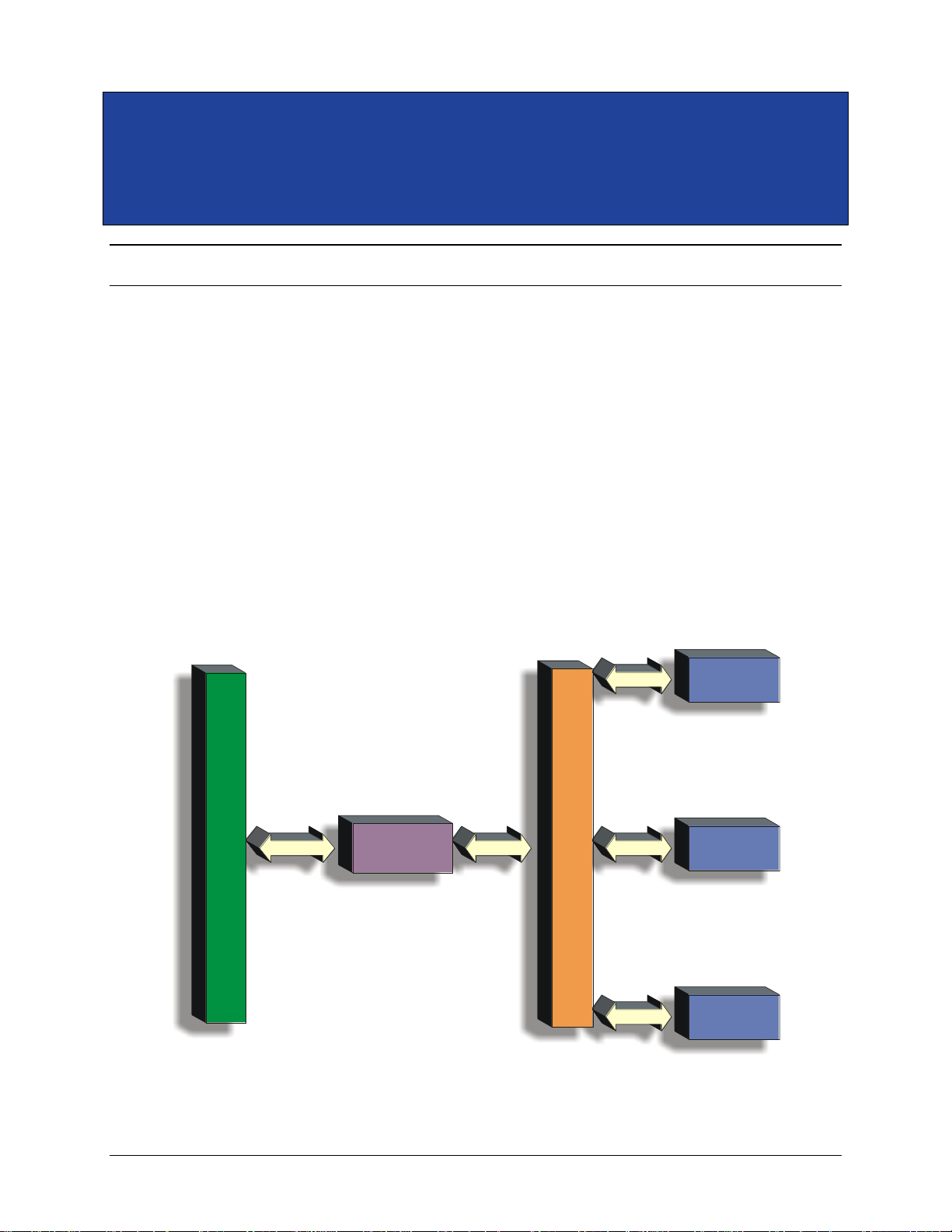
The VM2164 is a high-performance system level universal counter, designed to outperform
traditional rack-and-stack and other C-size VXIbus counters, but with a considerably smaller
footprint. A part of the VMIP (VXI Modular Instrumentation Platform) family of products, the
VM2164 can be combined with up to two other high-performance instruments on a single C-Size
card to form a customized and highly integrated instrument (see Figure 1-1).
This allows the user to reduce system size and cost by combining the VM2164 with two other
instrument functions in a single-wide C-size VXIbus module. Up to three VM2164s can also be
combined together on a single VXIbus card, making it an ideal choice for applications that require
multi-signal measurement functions, such as in automotive or medical electronic test.
A powerful combination for any automated test set is our single VXIbus module, VT2000
combining a 6.5 digit system DMM (VM2710A), a 200 MHz 1 ns universal counter (VM2164)
and a 50 MSample/s arbitrary waveform/function generator (VM3640A). Our single-slot timer
counter (VM2164) plus a Rubidium standard (VM3000) is another powerful combination.
V
X
I
B
U
S
I
N
T
E
R
N
A
L
V
M
I
P
B
U
S
VMIP
INTERFACE
VMIP
INSTRUMENT
MODULE #1
VMIP
INSTRUMENT
MODULE #2
VMIP
INSTRUMENT
MODULE #3
FIGURE 1-1 THE VMIP
™
PLATFORM
Page 14
VXI Technology, Inc.
14 VM2164 Introduction
Each VM2164 Counter/Timer is treated as an independent instrument in the VXIbus
chassis. Each has its own unique Logical Address and its own front panel FAIL and ACC
indicators. The ACC (ACCESS) LED flashes when read/write commands are being sent to
the module. The FAIL LED glows green to indicate that the board is receiving power. This
LED glows red when a fail condition has occurred.
PROGRAMMING
The VM2164 is programmed using message-based word serial protocol. The commands are
SCPI and IEEE-STD-488-2 compatible. VXIplug&play drivers are also provided to further
ease programming.
CALIBRATION
The calibration constants used to correct the data values are stored in non-volatile memory
and are password protected for security. These constants are determined when the
instrument is calibrated and can be changed as necessary. These constants may also be
queried at any time via a word-serial query and altered via a word-serial command (with the
password). All calibration is done using calibration DACs to adjust the gain and offset of
each channel. This eliminates the need for removing covers from the unit and allows for
automated calibration.
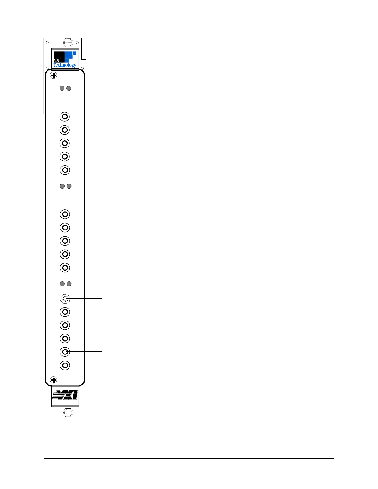
FIGURE 1-2 FRONT PANEL LAYOUT
CHANNEL 3 INPUT (Optional)
CHANNEL 1 INPUT
CHANNEL 2 INPUT
EXTERNAL REFERENCE OUTPUT
EXTERNAL REFERENCE INPUT
EXTERNAL ARM INPUT
bus
FAIL
ACC
FAIL
ACC
FAIL
ACC
Page 15

www.vxitech.com
VM2164 Introduction 15
BUILT-IN SOFTWARE FUNCTIONS
BUILT IN SOFTWARE FUNCTIONS
• Auto-Level
• Pulse Characterization
• Period
• Frequency
• Positive Pulse Width
• Negative Pulse Width
• Positive Duty Cycle
• Burst Frequency
• Rise Time
• Fall Time
• Burst Characterization
• BIT (Built-In Test)
• Clock On/Off – In/Out
FEATURES
FEATURES
FREQUENCY
Frequency
Frequency Ratio
Frequency in Bursts
Channel 3
PERIOD AND TIME
Period (Single)
Period (Average)
Positive Pulse Width
Negative Pulse Width
Rise Time
Fall Time
Time Interval
Time Interval Average
PHASE
VOLTAGE
VDC
V
P-P
V
MAX
V
MIN
ARMING
Arm Source
Arm Slope
Trigger Level
Arming Start Delay
Hold Off
Burst Sync Delay
Ch 1, Ch 2, Ext, VXI TTLT
Positive, Negative
Fixed (approximately TTL)
Events/Timed
Timed
Timed
MEASUREMENT STORAGE
Standard
1000 measurements
POSITIVE / NEGATIVE DUTY CYCLE
TOTALIZE
Page 16

VXI Technology, Inc.
16 VM2164 Introduction
GENERAL SPECIFICATIONS
INPUT SPECIFICATIONS
CHANNEL 1 & 2
Impedance
1 MΩ20 pF
50 Ω20 pF
Frequency Range
DC Coupled
AC Coupled
DC – 200 MHz
20 Hz – 200 MHz
50 kHz
155 kHz
Sensitivity
1x
20 mVrms – up to 50 MHz
40 mVrms – 50 MHz to 200 MHz
100 mV
P-P
– 5 to 10 ns pulse
50 mV
P-P
– Greater than 10 ns pulse
10x
200 mVrms – up to 50 MHz
400 mVrms – 50 MHz to 200 MHz
1.0 V
P-P
– 5 to 10 ns pulse
500 mV
P-P
– Greater than 10 ns pulse
Crosstalk
< -36 dB at 100 MHz into 50 Ω
Input Damage Level
1x / 10x
50 Ω Input
240 Vrms (DC + ACrms) to 2 kHz linearly derated to 5 Vrms at
100 kHz. 5 Vrms above 100 kHz
5 Vrms – DC to 200 MHz
Trigger Level Range
1x
10x
±5.0 V
±50 V
Trigger Level Resolution
1x
2.5 mV
10x
25 mV
Trigger Sensitivity
1x
20 mVrms Sine Wave (< 50 MHz)
40 mVrms Sine Wave (50 MHz to 200 MHz)
10x
200 mVrms Sine Wave (< 50 MHz)
400 mVrms Sine Wave (50 MHz to 200 MHz)
Auto-Trigger
Automatically set to the 50% point between the signal’s peak-to-peak
levels. The signal’s 10% and 90% points are sued for rise and fall
time measurements.
Trigger Error (seconds)
pointTrigger @ rate SlewInput
EE
2
Signal
2
Input
, (E
Signal
is the input signal noise)
E
Input
(RMS Noise of the Input)
1x
10x
2 mVrms, (500 μVrms typical)
20 mVrms, (5 mVrms typical)
Trigger Level Timing Error
1x
Stopat Rate SlewInput
mV 12.5
Startat Rate SlewInput
mV 12.5
10x
Stopat Rate SlewInput
mV 125
Startat Rate SlewInput
mV 125
Base Resolution and Accuracy
t
res
50 ps
t
acc
0.4 ns typical, 0.8 ns worst case
Differential Channel Error
100 ps
Page 17

www.vxitech.com
VM2164 Introduction 17
CHANNEL 3 INPUT (OPTION 17)
Frequency Range
150 MHz to 3.0 GHz
Sensitivity
150 MHz – 2.4 GHz
2.4 GHz – 3.0 GHz
-25 dBm to +19 dBm
-19 dBm to +19 dBm
Impedance
50 Ω
Input Coupling
AC
Input Damage Level
5 Vrms
EXTERNAL REFERENCE OUTPUT
Frequency
10 MHz
Coupling
DC
Output Impedance
50 Ω
Output Level Low
0.8 V into > 10 kΩ
Output Level High
4.2 V into > 10 kΩ
Gate Time
Programmable from 200 μs to 99.9999 s
EXTERNAL REFERENCE INPUT
Frequency
10 MHz
Coupling
AC
Input Impedance
1 kΩ
Voltage Range
500 mVrms to 12 Vrms
Input Damage Level
15 Vrms
EXTERNAL ARM INPUT
Coupling
DC
Impedance
1 kΩ
Input Threshold
1.3 V fixed
Input Signal Level
500 mV
P-P
about the input threshold
Pulse Width
50 ns
Transition Time
250 ns
TTL TRIGGER BUS ARMING
Input
Any VXIbus TTL Trigger line may be selected for arming
(Rising or Falling edge sensitive)
Output
Any VXIbus TTL Trigger line may be selected to follow the
measurement gate signal (polarity is programmable)
MEASUREMENTS
FREQUENCY MEASUREMENTS
Input 1 & 2 Range
500 μHz to 200 MHz (DC coupled)
20 Hz to 200 MHz (AC coupled)
Input 1 & 2 Resolution
Time Gate
Error)Trigger (StopError)Trigger (Start t
Frequency
222
res
Input 1 & 2 Systematic Error
GateTime
t
Error Base Time Frequency
acc
Input 3 Frequency Range
150 MHz to 2.5 GHz
Input 3 Resolution
Time Gate
Error)Trigger (StopError)Trigger (Start t
Frequency 32
222
res
Input 3 Systematic Error
GateTime
t
Error Base Time Frequency 32
acc
Accuracy
INPUTINPUT
Time Gate
Error Systematic
1
Error Base Time Resolution ff
Page 18

VXI Technology, Inc.
18 VM2164 Introduction
FREQUENCY RATIO
Input 1 & 2 Range
500 μHz to 200 MHz (DC coupled)
20 Hz to 200 MHz (AC coupled)
Results Range
CH1
CH2
,
CH2
CH1
2.5 x 10
-12
to 4.0 x 10¹¹
Resolution
CH2
CH1
1Count
Count
-
Count
Count
CH2
CH1
CH2
CH1
Resolution
CH1
CH2
Count
1Count
-
Count
Count
CH1
CH2
CH1
CH2
Input 3 Range
150 MHz to 2.5 GHz
Results Range
CH3
CH2
CH3
CH1
CH2
CH3
CH1
CH3
,,,
2.0 x 10
-13
to 5.0 x 10¹²
Resolution
CH3
CH2
,
CH3
CH1
32Count
Count
-
Count
Count
CH3
CH2or CH1
CH3
CH2or CH1
Resolution
CH2
CH3
,
CH1
CH3
1Count
Count
-
Count
Count
CH2or CH1
CH3
CH2or CH1
CH3
PERIOD MEASUREMENT
Input 1 & 2 Range
5 ns to 2000 s
Resolution
222
res
Error)Trigger (StopError)Trigger (Start t
Systematic Error
Time Gate
t
Error Base TimePeriod
acc
PHASE MEASUREMENT
Range
0° to 360° or -180° to +180°
Resolution
2
22
res
360
Phase
1ErrorTrigger 4t360Frequency
Systematic Error
Error Channel alDifferenti
Time Phase
t
Period
t
ErrorTrigger 360Frequency
accacc
TIME INTERVAL MEASUREMENTS
Range
2 ns to 1 x 10⁶ s
Resolution – Single Shot
222
res
Error)Trigger (StopError)Trigger (Start t
Systematic Error
Error Channel alDifferenti
Interval Time
t
Error Base TimeInterval Time
acc
PULSE WIDTH MEASUREMENT
Range
5 ns to 20 ms
Resolution – Single Shot
2
222
res
Error Timing LevelTrigger Error)Trigger (StopError)Trigger (Start t
Systematic Error
Width
t
Error Base TimeWidth
acc
Accuracy
WidthPulse
Error Systematic
1
WidthPulseError Base Time Resolution
RISE AND FALL TIME MEASUREMENT
Range
10 ns to 1000 s
Resolution – Single Shot
2
222
res
Error Timing LevelTrigger Error)Trigger (StopError)Trigger (Start t
Systematic Error
Interval Time
t
Error Base TimeInterval Time
acc
Page 19

www.vxitech.com
VM2164 Introduction 19
DC VOLTAGE MEASUREMENT
Range
1x
±4 V
10x
±40 V
Resolution
1x
2.5 mV
10x
25 mV
Accuracy
1x
±12.5 mV
10x
±125 mV
PEAK VOLTAGE MEASUREMENT
Range
1x
±5 V
10x
±50 V
Resolution
1x
2.5 mV
10x
25 mV
Accuracy
1x
±12.5 mV
10x
±125 mV
Page 20

VXI Technology, Inc.
20 VM2164 Introduction
OSCILLATOR SPECIFICATIONS
NO OSCILLATOR – USE VXI 10 MHZ
Performance
±100 ppm
EX2500A
Performance
±50 ppm
TCXO – STANDARD
Performance
High Performance
Aging
±1 x 10⁻⁶/year
Temperature
±3 x 10⁻⁶ (0°C to 50°C)
Adjustment Range
±3 x 10⁻⁶ minutes
Warm Up Time
N/A
OCXO – OPTION 16
Performance
Ultra High Performance
Aging
±1 x 10⁻⁷/year
±1 x 10⁻⁹/day
Temperature
±1 x 10⁻⁷ (0°C to 50°C)
Adjustment Range
±4 x 10⁻⁷ minutes
Warm Up Time
< 3 minutes
Page 21

www.vxitech.com
VM2164 Preparation for Use 21
SECTION 2
PREPARATION FOR USE
INTRODUCTION
When the VMIP is unpacked from its shipping carton, the contents should include the following
items:
(1) VMIP VXIbus module
(1) VM2164 Counter / Timer User’s Manual (this manual)
All components should be immediately inspected for damage upon receipt of the unit.
The chassis should be checked to ensure that it is capable of providing adequate power and cooling
for the VMIP. Once the chassis is found adequate, the VMIP’s logical address and the chassis’
backplane jumpers should be configured prior to the VMIP’s installation. Once these steps are
complete, it may then be installed into an appropriate chassis in any slot other than slot zero.
CALCULATING SYSTEM POWER AND COOLING REQUIREMENTS
It is imperative that the chassis provide adequate power and cooling for this module. Referring to
the chassis operation manual, confirm that the power budget for the system (the chassis and all
modules installed therein) is not exceeded and that the cooling system can provide adequate
airflow at the specified backpressure.
It should be noted that if the chassis cannot provide adequate power to the module, the instrument
might not perform to specification or possibly not operate at all. In addition, if adequate cooling is
not provided, the reliability of the instrument will be jeopardized and permanent damage may
occur. Damage found to have occurred due to inadequate cooling will also void the module's
warranty.
Page 22
VXI Technology, Inc.
22 VM2164 Preparation for Use
SETTING THE CHASSIS BACKPLANE JUMPERS
Please refer to the chassis operation manual for further details on setting the backplane jumpers.
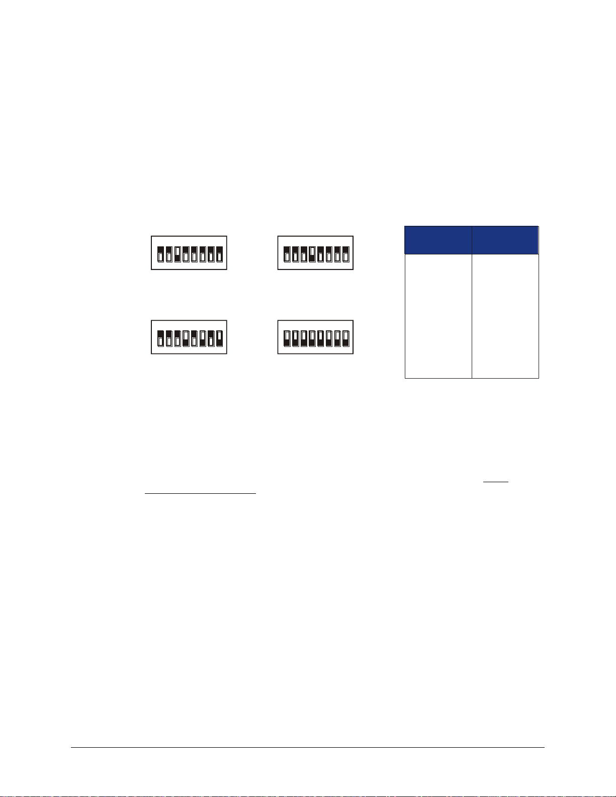
SETTING THE LOGICAL ADDRESS
The logical address of the VM2164 is set by a single 8-position DIP switch located near the VMIP
module’s backplane connectors (this is the only switch on the module). The switch is labeled with
positions 1 through 8 and with an ON position. A switch pushed toward the ON legend will
signify a logic 1; switches pushed away from the ON legend will signify a logic 0. The switch
located at position 1 is the least significant bit while the switch located at position 8 is the most
significant bit. See Figure 2-1 for examples of setting the logical address switch.
SET TO 4
1ON2 3 4 5 6 7 8
SET TO 168
1 2 3 4 5 6 7 8
SET TO 8
1ON2 3 4 5 6 7 8
SET TO 255
1
ON ON
2 3 4 5 6 7 8
1
2
3
4
5
6
7
8
Switch
Position
1
2
4
8
16
32
64
128
Switch
Value
ON ON
(Dynamic)
FIGURE 2-1 LOGICAL ADDRESS SWITCH SETTING EXAMPLES
The VMIP may contain three separate instruments and will allocate logical addresses as required
by the VXIbus specification (revisions 1.3 and 1.4). The logical address of the instrument is set on
the VMIP carrier. The VMIP logical addresses must be set to an even multiple of 4 unless
dynamic addressing is used. Switch positions 1 and 2 must always be set to the OFF position.
Therefore, only addresses of 4, 8, 12, 16, ...252 are allowed. The address switch should be set for
one of these legal addresses and the address for the second instrument (the instrument in the center
position) will automatically be set to the switch set address plus one; while the third instrument
(the instrument in the lowest position) will automatically be set to the switch set address plus two.
If dynamic address configuration is desired, the address switch should be set for a value of 255
(All switches set to ON). Upon power-up, the slot 0 resource manager will assign the first
available logical addresses to each instrument in the VMIP module.
If dynamic address configuration is desired, the address switch should be set for a value of 255.
Upon power-up, the slot 0 resource manager will assign logical addresses to each instrument in the
VMIP module.
Page 23

www.vxitech.com
VM2164 Command Dictionary 23
SECTION 3
COMMAND DICTIONARY
INTRODUCTION
This section presents the instrument command set. It begins with an introduction to the Standard
Commands for Programmable Instruments (SCPI) programming language, detailing proper syntax
and explaining SCPI nomenclature. The introduction is then followed by an alphabetical listing of
all the commands supported by the VM2164 Counter/Timer. The remainder of this section is
devoted to describing each command, one per page, in detail. The description is presented in a
way to assist the user in the use of each command. Every command entry describes the exact
command and/or query syntax, the use and range of parameters, and a description of the
command’s purpose.
THE SCPI PROGRAMMING LANGUAGE
The VM2164 is a VXIbus message-based device whose command set is compliant with the SCPI
programming language. All module commands are sent over the VXIbus backplane to the module.
Commands may be in upper, lower or mixed case. All numbers are sent in ASCII decimal unless
otherwise noted.
The SCPI programming language is a tree-structured language based on IEEE-STD-488.2
Specifications. It utilizes the IEEE-STD-488.2 Standard command and the device dependent
commands are structured to allow multiple branches off the same trunk to be used without
repeating the trunk. To use this facility, terminate each branch with a semicolon. For example,
CALibration:SECure:CODE and CALibration:SECure:STATe are both branches off the
CALibration: trunk and can be combined as follows:
CALibration:SECure:CODE <string>;STATe <boolean>,<string>
The above command is the same as the these two commands:
CALibration:SECure:CODE <string>
CALibration:SECure:STATe <boolean>,<string>
See the Standard Commands for Programmable Instruments (SCPI) Manual, Volume 1: Syntax &
Style, Section 6, for more information.
Page 24

VXI Technology, Inc.
24 VM2164 Command Dictionary
The SCPI commands in this section are listed in upper and lower case. Character case is used to
indicate different forms of the same command. Keywords can have both a short form and a long
form (some commands only have one form). The short form uses just the keyword characters in
uppercase. The long form uses the keyword characters in uppercase plus the keyword characters in
lowercase. Either form is acceptable. Note that there are no intermediate forms. All characters of
the short form or all characters of the long form must be used. Short forms and long forms may be
freely intermixed. The actual commands sent can be in upper case, lower case or mixed case (case
is only used to distinguish short and long form for the user). As an example, these commands are
all correct and all have the same effect:
CALibration:SECure:CODE <string>
calibration:secure:code <string>
CALIBRATION:SECURE:CODE <string>
CAL:SECure:CODE <string>
CAL:SEC:CODE <string>
cal:sec:code <string>
The following command is not correct because it uses part of the long form of CALibration, but
not all the characters of the long form:
calib:sec:code <value> (incorrect syntax - extra "ib"- only cal or
calibration is correct)
All of the SCPI commands also have a query form unless otherwise noted. Query forms contain a
question mark (?). The query form allows the system to ask what the current setting of a parameter
is. The query form of the command generally replaces the parameter with a question mark (?).
Query responses do not include the command header. This means only the parameter is returned:
no part of the command or "question" is returned.
NOTATION
Keywords or parameters enclosed in square brackets ([ ]) are optional. If the optional part is a
keyword, the keyword can be included or left out. Omitting an optional parameter will cause its
default to be used.
Parameters are enclosed by angle brackets (< >). Braces ({ }), or curly brackets, are used to
enclose one or more parameters that may be included zero or more times. A vertical bar (|), read
as "or", is used to separate parameter alternatives.
ALPHABETICAL COMMAND LISTING
The tables on the pages that follow provide an alphabetical listing of each command supported by
the VM2164 Counter/Timer along with a brief definition. If an X is found in the column titled
“*RST” (Reset), then the value or setting controlled by this command is possibly changed by the
execution of the *RST command. If an X is not found, then the *RST has no effect. The *RST
value is provided with each command. This value is set when the unit is powered up or when an
*RST or a RESet command is executed. Note that calibration values revert to the values stored in
non-volatile memory upon reset. Using the CALibration:DEFault command will return calibration
values back to known, factory preset values. In order for CALibration commands/queries to be
executed, calibration security must be turned off. If security is not turned off, a “-203, Command
Protected” error will be returned. See CALibration:SECure:CODE for information on calibration
security.
Page 25

VM2164 Command Dictionary
25
www.vxitech.com
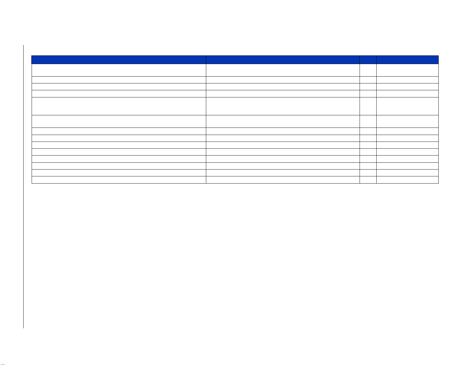
ALPHABETICAL COMMAND LISTING
Command
Description
*RST
*RST Value
*CLS
Clears all status and event registers.
*ESE
Sets the bits of the Event Status Enable Register.
*ESR?
Queries and clears the Standard Event Status Register.
*IDN?
Queries the module for its identification string.
*OPC
Sets the OPC bit in the Event Status Register.
*RST
Resets the module’s hardware and software to a known state.
*SRE
Sets the service request enable register.
*STB?
Queries the Status Byte Register.
*TRG
Causes a trigger event to occur.
*TST?
Causes a self-test procedure to occur and queries the results.
*WAI
Halts execution of additional commands and queries until the No Operation
Pending message is true.
ABORt
This command aborts any actions in process.
ARM([:SEQuence1]|[:STARt])[:LAYer]:DELay
Specifies a time delay to occur after the receipt of an arm signal before actually
arming the counter.
X
0.000000000000000e+00
ARM([:SEQuence1]|[:STARt])[:LAYer]:ECOunt
Specifies the number of arm signals to count prior to arming the counter.
X
0.000000000000000e+00
ARM([:SEQuence1]|[:STARt])[:LAYer]:IMMediate
To create a one time entry by the counter into the armed state.
ARM([:SEQuence1]|[:STARt])[:LAYer]:MODE
If the counter has been configured for an array measurement, this command
specifies whether the counter will perform one or all operations when an ARM
command is received.
X
ALL
ARM([:SEQuence1]|[:STARt])[:LAYer]:SLOPe
Specifies the slope of the counter external arm signal.
X
POS
ARM([:SEQuence1]|[:STARt])[:LAYer]:SOURce
Selects or queries the start arming source.
X
IMM
ARM([:SEQuence1]|[:STARt])[:LAYer]:SOURce:CATalog[:ALL]?
Lists all trigger sources available for use with the ARM:SOUR command.
ARM([:SEQuence1]|[:STARt])[:LAYer]:SOURce:CATalog:DELayable?
Lists all delayable trigger sources available for use with the ARM:SOUR
command.
ARM([:SEQuence1]|[:STARt])[:LAYer]:SOURce:CATalog:FIXed?
Lists all fixed trigger sources available for use with the ARM:SOUR
command.
ARM(:SEQuence2|:STOP)[:LAYer]:DELay
Specifies a time delay to occur after receipt of a stop arm signal prior to
actually disarming the counter.
X
0.000000000000000e+00
ARM(:SEQuence2|:STOP)[:LAYer]:ECOunt
Specifies the number of stop arm signals the instrument will count prior to
disarming the counter.
X
0.000000000000000e+00
ARM(:SEQuence2|:STOP)[:LAYer]:IMMediate
Causes a one-time exit by the counter from the armed state.
ARM(:SEQuence2|:STOP)[:LAYer]:SOURce
Selects or queries the stop arming source to be used when the counter is
initiated.
X
IMM
ARM(:SEQuence2|:STOP)[:LAYer]:SOURce:CATalog[:ALL]?
Lists all trigger sources available for use with the ARM:STOP:SOUR
command.
X
See command for possible
query responses
ARM(:SEQuence2|:STOP)[:LAYer]:SOURce:CATalog:DELayable?
Lists all fixed trigger sources available for use with the ARM:STOP:SOUR
command.
ARM(:SEQuence2|:STOP)[:LAYer]:SOURce:CATalog:FIXed?
Lists all delayable trigger sources available for use with ARM:STOP:SOUR
command.
Page 26

26
VM2164 Command Dictionary
VXI Technology, Inc.
ALPHABETICAL COMMAND LISTING (CONT.)
Command
Description
*RST
*RST Value
CALCulate:AVERage?
This query calculates the average of a specified number of measurements in the
memory buffer.
CALCulate:LIMit:ENVelope[:DATA]?
This command searches for all the input data values within an envelope of
values defined as being above, below, or in between as set boundary of values.
X
-9.989999999999990e+99,
-9.989999999999990e+99
CALCulate:LIMit:FCOunt?
This query performs a limit test on the current available data.
CALCulate:LIMit:LOWer[:DATA]?
Searches for all the input data values below a certain <threshold>.
X
-9.989999999999990e+99
CALCulate:LIMit:REPort[:DATA]?
This query returns the <memory_index> and <failed_value> values collected.
CALCulate:LIMit:UPPer[:DATA]?
Searches for all the input data values above a certain <threshold>.
X
-9.989999999999990e+99
CALCulate:MAXimum?
This query calculates and returns the maximum value of a set of data.
CALCulate:MEDian?
This query calculates and returns the median value of a set of data.
CALCulate:MINimum?
This query calculates and returns the minimum value of a set of data.
CALCulate:SDEViation?
This query calculates and returns the standard deviation for a set of data.
CALCulate:TRANsform:HISTogram:ABOVe?
This query returns the number of points above the maximum value in a
histogram calculation.
CALCulate:TRANsform:HISTogram:BELow?
This query returns the number of points below the minimum value in a
histogram calculation.
CALCulate:TRANsform:HISTogram:COUnt?
Determines the number of data points to include in a histogram calculation.
X 1 CALCulate:TRANsform:HISTogram:POINts?
Sets the number of intervals in a histogram calculation.
X
1
CALCulate:TRANsform:HISTogram:RANGe?
Sets the minimum and maximum values to use in a histogram calculation.
X
-9.989999999999990e+99,
-9.989999999999990e+99
CALCulate:TRANsform:HISTogram:RANGe:AUTO?
This command sets the minimum and maximum values to use in a histogram
calculation.
X
1
CALCulate:TRANsform:HISTogram?
This query calculates and returns the histogram for a set of data.
CALCulate:VARiance?
This query calculates and returns the variance for a set of data.
CALibration:COSCillator
Calibrates the reference oscillator. (Must have Option 15 or Option 16
installed)
Assumes the last
value stored in
non-volatile memory
CALibration:DAC:OFFSet
Calibrates one of the two factors used by the DAC.
CALibration:DAC:SLOPE
Calibrates one of two factors used by the DAC.
CALibration:DEFault
Initializes calibration values to known values.
CALibration:SECure:CODE
Sets the code required to disable calibration security.
CALibration:SECure[:STATe]
Enable or disable calibration security.
CALibration:STORe
Stores calibration data into non-volatile memory.
CALibration:TEC:OFFSet
Calibrates one of three factors used by the TEC circuitry.
CALibration:TEC:STARtslope
Calibrates one of three factors used by the TEC circuitry.
CALibration:TEC:STOPslope
Calibrates one of three factors used by the TEC circuitry.
CALibration:TINTerval:OFFSet
This command compensates for the differences between Channel 1 and
Channel 2.
X
Page 27

VM2164 Command Dictionary
27
www.vxitech.com
ALPHABETICAL COMMAND LISTING (CONT.)
Command
Description
*RST
*RST Value
CONFigure[1|2](:SCALar]|:ARRay):NDUTy cycle|PDUTCycle|DCYCle
This command configures a positive or negative duty cycle measurement.
X
Array size = 1
Dcycle Reference = 50
CONFigure[1|2](:SCALar]|:ARRay):NWIDth|PWIDth
This command configures the counter to measure the positive or negative pulse
width time of the signal on the CONFigure suffix input channel.
X
Array size = 1
Dcycle Ref = 50
CONFigure[1|2](:SCALar]|:ARRay):PHASe
This command configures a phase measurement.
X
1
CONFigure[1|2](:SCALar]|:ARRay):RTIMe|FTIMe|RISE:TIME|FALL:TIME
This command configures the counter to measure the rise or fall time of the
signal on the CONFigure suffix input channel.
X
Array size = 1
Low Reference = 10
High Reference = 90
CONFigure[1|2](:SCALar]|:ARRay):TINTerval
This command sets the counter to make a time interval measurement.
X
1
CONFigure[1|2](:SCALar]|:ARRay)[:VOLTage]:[:…]
These commands configure the counter to measure the voltage on the
CONFigure suffix input channel.
X
1
CONFigure[1|2|3](:SCALar]|:ARRay):FREQuency
This command configures the counter to measure the frequency of the signal
on the CONFigure suffix input channel.
X
1
CONFigure[1|2|3](:SCALar]|:ARRay):FREQuency:RATio
This command configures the counter to measure the ratio of the frequencies
of the signals on the CONFigure suffix input channel and <second channel>.
X
1
CONFigure[1|2|3](:SCALar]|:ARRay):PERiod
This command configures the counter to measure the period of the signal on
the CONFigure suffix input channel.
X
1
CONFigure[1|2|10|20](:SCALar]|:ARRay):TOTalize
This command configures a totalized measurement.
FETCh[:…]?
This query returns the values of measurements.
FETCh:COUNt?
This query returns the number of measurements completed.
X 0 FETCh:TOTalize?
This query returns the total counts from Channel 1 and 2
FETCh:[:VOLTage][:…]?
This query sets up to return the results of the pervious voltage measurement.
INITiate:CONTinuous
Verifies whether the counter is taking continuous measurements.
X
0 if not continuous,
1 if continuous
INITiate[:IMMediate]
This command initiates the current trigger sequence.
INPut[1|2]:ATTenuation
This command sets the input block signal attenuator for the specified channel.
X
1
INPut[1|2]:COMParator[1|2]:LEVel:RELative
This command sets the comparator threshold level voltage of the channel and
comparator selected.
X
0
INPut[1|2]:COMParator[1|2]:SLOPe
This command sets the slope for the selected input channel and comparator.
X
POS
INPut[1|2]:COUPling
This command sets the input block signal coupling for the specified channel
AC or DC.
X
AC
INPut[1|2]:FILTer[:FREQuency]
This command sets the frequency of the low pass filter.
X
20e6 below 30 MHz
100e6 at or above 30 MHz
INPut[1|2]:FILTer[:STATe]
This command sets the input block signal low-pass filter state for the selected
channel to ON or OFF.
X
ON
INPut[1|2]:IMPedance
This command sets the input terminating impedance for the specified channel.
X
1000000.000000 (1e6)
INPut[1|2]:SETup
This command sets up Input Channel 1 or 2 by specifying an expected peak-topeak input voltage and optionally an expected input offset voltage.
INPut[1|2]:SETup:AUTO
This command controls the auto setup of Input Channels 1 and 2.
X
ONCE
Page 28

28
VM2164 Command Dictionary
VXI Technology, Inc.
ALPHABETICAL COMMAND LISTING (CONT.)
Command
Description
*RST
*RST Value
INPut[1|2]:SETup:AUTO:TIMe
This command sets the duration of time that will be allowed for a signal to
occur before a measurement is aborted when autotriggered.
X
0.02
INPut[1|2]:SETup:TIMe
This command sets the duration of time after an INITiate command that will be
allowed for a signal to occur before a measurement is aborted.
X
0.04
MEASure[1|2]([:SCALar]|:ARRay]:DCYCle|NDUTycycle|PDUTycycle?
This query performs a positive or negative duty cycle measurement.
X
1
MEASure[1|2]([:SCALar]|:ARRay):NWIDth|PWIDth?
This query configures the counter to measure the positive or negative pulse
width time of the signal on the MEASure suffix input channel.
X
1
MEASure[1|2]([:SCALar]|:ARRay):PHASe?
This query performs a phase measurement.
X
1
MEASure[1|2]([:SCALar]|:ARRay):RTIMe|FTIMe|RISE:TIME|FALL:TIME?
This query configures the counter to measure the rise and or fall time of the
signal on the MEASure suffix input channel.
X
Array size = 1
Low reference = 10
High reference = 90
MEASure[1|2]([:SCALar]|:ARRay):TINTerval?
Sets the counter to make a time interval measurement and fetch the result.
MEASure[1|2]([:SCALar]|:ARRay)[:VOLTage][:…]?
These queries configure the counter to measure the voltage on the MEASure
suffix input channel.
X
1
MEASure[1|2|3]([:SCALar]|:ARRay):FREQuency?
Configures the counter to measure the frequency of the signal on the MEASure
suffix input channel.
X
1
MEASure[1|2|3]([:SCALar]|:ARRay):FREQuency:RATio?
This query configures the counter to measure the ratio of the frequencies of the
signals on the MEASure suffix input channel and <second channel>.
X
1
MEASure[1|2|3]([:SCALar]|:ARRay):PERiod?
Configures the counter to measure a period of the signal on the MEASure
suffix input channel.
X
1
MEASure[1|2|10|20][:SCALar]]:TOTalize?
This query performs a totalize measurement.
OUTPut:CLOCk
This command toggles the External Reference as a useable reference clock.
X
1
OUTPut:TTLTrg
This command selects the TTL trigger line that will receive the output.
X
0
OUTPut:TTLTrg:STATe
This command toggles the use of TTL trigger lines as usable outputs.
X
ON
READ?
This query causes an INITiate:IMMediate action and a FETCh? query.
RESet
Resets the module’s hardware and software to a known state.
SENSe:APERture
This command sets the counter measurement aperture <time>.
X
0.100000
SENSe:COUNt
This command sets the counter to do <array size> number of measurements.
X 1 SENSe:EVENts
This command sets the counter <# of events>.
X
1000
SENSe:MODe
This command sets the counter to make a measurement for a length of time
(APERture) or for a number of cycles of the input signal (EVENTs).
X
APER
SENSe[1,2]:FUNCtion
This command selects a function and input channel without changing most of
the setup of the counter.
X
FREQ
SENSe[1|2|3]:FUNCtion
The SENSe:FUNCtion command selects a function and input channel without
changing most of the counter setup.
X
FREQ
SENSe[1|2|10|20]:FUNCtion
The SENSe:FUNCtion command selects a function and input channel without
changing most of the counter setup.
Page 29
VM2164 Command Dictionary
29
www.vxitech.com
ALPHABETICAL COMMAND LISTING (CONT.)
Command
Description
*RST
*RST Value
SOURce:COSCillator[:SOURce]
The SOURce subsystem commands are used to command the TCXO1 option
(if available).
X
ROSC, if Option 15 is used,
then TCXO1 is returned
SOURce:COSCillator:VALue?
This query returns the current oscillator frequency.
X
9.9999999999e+06
TEST?
Performs an internal communication test.
TEST:ALL?
The Test subsystem handles the self test operations of the instrument.
UNIT:ANGLe
The UNIT subsystem command specifies the units for the phase measurements
as either degrees or radians and determines whether the units will be positive or
centered around zero.
X
Unit = RAD
Zero = MIN
STATus:OPERation:CONDition?
The STATus:OPERation:CONDition query returns the current operational
status of the counter.
X
0
STATus:OPERation:ENABle
Sets the Questionable Status Enable Register.
STATus:OPERation:NTR
Sets the negative transition filter.
STATus:OPERation:PTR
Sets the positive transition filter.
STATus:OPERation[:EVENt]?
Queries the Operation Status Register's event register.
STATus:PRESet
Presets the Status Registers.
STATus:QUEStionable:CONDition?
Queries the Questionable Status Condition Register.
STATus:QUEStionable:ENABle
Sets the Questionable Status Enable Register.
STATus:QUEStionable[:EVENt]?
Queries the Questionable Status Event Register.
Page 30

VXI Technology, Inc.
30 VM2164 Command Dictionary
COMMAND DICTIONARY
The remainder of this section is devoted to the actual command dictionary. Each command is fully
described on its own page. In defining how each command is used, the following characteristics
are used:
Purpose
Describes the purpose of the command.
Type
Describes the type of event, such as type or setting.
Command Syntax
Details the exact command format
Command Parameters
Describes the parameters sent with the command and their legal parameters
*RST Value
Describes the value assumed when the *RST (reset) command is sent.
Query Syntax
Details the exact query form of the command.
Query Parameters
Describes the parameters sent with the command and their legal range. The default
parameter values are assumed the same as in the command form unless described
otherwise.
Query Response
Describes the format of the query response and the valid range of output.
Description
Describes in detail what the command does and refers to additional sources.
Examples
Presents the proper use of each command and its query (when available).
Related Commands
Lists commands that affect the use of this command or commands that are affected by
this command.
Page 31

www.vxitech.com
VM2164 Command Dictionary 31
Page 32

VXI Technology, Inc.
32 VM2164 Command Dictionary
IEEE 488.2 COMMON COMMANDS
*CLS
Purpose
Clears all status and event registers
Type
IEEE 488.2 Common Command
Command Syntax
*CLS
Command Parameters
N/A
*RST Value
N/A
Query Syntax
N/A
Query Parameters
N/A
Query Response
N/A
Description
This command clears the Status Event Register, Operation Status Register and the
Questionable Data/Signal Register. It also clears the OPC flag and clears all queues
(except the output queue).
Examples
Command / Query
Response (Description)
*CLS
(Clears all status and event registers)
Related Commands
N/A
Page 33

www.vxitech.com
VM2164 Command Dictionary 33
*ESE
Purpose
Sets the bits of the Event Status Enable Register
Type
IEEE 488.2 Common Command
Command Syntax
*ESE <mask>
Command Parameters
<mask> = numeric ASCII value
*RST Value
N/A – required parameter
Query Syntax
*ESE?
Query Parameters
N/A
Query Response
Numeric ASCII value from 0 to 255
Description
The Event Status Enable (ESE) command is used to set the bits of the Event Status
Enable Register. See ANSI/IEEE 488.2-1987 section 11.5.1 for a complete
description of the ESE register. A value of 1 in a bit position of the ESE register
enables generation of the Event Status Bit (ESB) in the Status Byte by the
corresponding bit in the Event Status Register (ESR). If the ESB is set in the Service
Request Enable (SRE) register, then an interrupt will be generated. See the *ESR?
command for details regarding the individual bits. The ESE register layout is:
Bit 0 - Operation Complete
Bit 1 - Request Control
Bit 2 - Query Error
Bit 3 - Device Dependent Error
Bit 4 - Execution Error
Bit 5 - Command Error
Bit 6 - User Request
Bit 7 - Power On
The Event Status Enable query reports the current contents of the Event Status Enable
Register.
Examples
Command / Query
Response (Description)
*ESE 36
*ESE?
36 (Returns the value of the event status enable register)
Related Commands
*ESR?
Page 34

VXI Technology, Inc.
34 VM2164 Command Dictionary
*ESR?
Purpose
Queries and clears the Standard Event Status Register
Type
IEEE 488.2 Common Command
Command Syntax
N/A
Command Parameters
N/A
*RST Value
N/A
Query Syntax
*ESR?
Query Parameters
N/A
Query Response
Numeric ASCII value from 0 to 255
Description
The Event Status Register (ESR) query - queries and clears the contents of the
Standard Event Status Register. This register is used in conjunction with the ESE
register to generate the Event Status Bit (ESB) in the Status Byte. The layout of the
ESR is:
Bit 0 - Operation Complete
Bit 1 - Request Control
Bit 2 - Query Error
Bit 3 - Device Dependent Error
Bit 4 - Execution Error
Bit 5 - Command Error
Bit 6 - User Request
Bit 7 - Power On
The Operation Complete bit is set when it receives an *OPC command.
The Query Error bit is set when data is over-written in the output queue. This could
occur if one query is followed by another without reading the data from the first query.
The Execution Error bit is set when an execution error is detected. Errors that range
from -200 to -299 are execution errors.
The Command Error bit is set when a command error is detected. Errors that range
from -100 to -199 are command errors.
The Power On bit is set when the module is first powered on or after it receives a reset
via the VXI Control Register. Once the bit is cleared (by executing the *ESR?
command) it will remain cleared.
Examples
Command / Query
Response (Description)
*ESR?
4
Related Commands
*ESE
Page 35

www.vxitech.com
VM2164 Command Dictionary 35
*IDN?
Purpose
Queries the module for its identification string
Type
IEEE 488.2 Common Command
Command Syntax
N/A
Command Parameters
N/A
*RST Value
N/A
Query Syntax
*IDN?
Query Parameters
N/A
Query Response
ASCII character string
Description
The Identification (IDN) query returns the identification string of the module. The
response is divided into four fields separated by commas. The first field is the
manufacturer’s name, the second field is the model number, the third field is an
optional serial number and the fourth field is the firmware revision number. If a serial
number is not supplied, the third field is set to 0 (zero).
Examples
Command / Query
Response (Description)
*IDN?
VXI Technology, Inc.,VM2164,0,1.0
(The revision listed here is for reference only;
the response will always be the current revision
of the instrument.)
Related Commands
N/A
Page 36

VXI Technology, Inc.
36 VM2164 Command Dictionary
*OPC
Purpose
Sets the OPC bit in the Event Status Register
Type
IEEE 488.2 Common Command
Command Syntax
*OPC
Command Parameters
N/A
*RST Value
N/A
Query Syntax
*OPC?
Query Parameters
N/A
Query Response
1
Description
The Operation Complete (OPC) command sets the OPC bit in the Event Status
Register when all pending operations have completed. The OPC query will return a 1
to the output queue when all pending operations have completed.
Examples
Command / Query
Response (Description)
*OPC
(Sets the OPC bit in the Event Status Register)
*OPC?
1 (Returns the value of the Event Status Register)
Related Commands
*WAI
Page 37

www.vxitech.com
VM2164 Command Dictionary 37
*RST
Purpose
Resets the module’s hardware and software to a known state
Type
IEEE 488.2 Common Command
Command Syntax
*RST
Command Parameters
N/A
*RST Value
N/A
Query Syntax
N/A
Query Parameters
N/A
Query Response
N/A
Description
The Reset (RST) command resets the module’s hardware and software to a known
state. See the command index at the beginning of this chapter for the default parameter
values used with this command.
Examples
Command / Query
Response (Description)
*RST
(Resets the module)
Related Commands
N/A
Page 38

VXI Technology, Inc.
38 VM2164 Command Dictionary
*SRE
Purpose
Sets the service request enable register
Type
IEEE 488.2 Common Command
Command Syntax
*SRE <mask>
Command Parameters
<mask> = Numeric ASCII value from 0 to 255
*RST Value
None – required parameter
Query Syntax
*SRE?
Query Parameters
N/A
Query Response
Numeric ASCII value from 0 to 255
Description
The Service Request Enable (SRE) mask is used to control which bits in the status byte
generate back plane interrupts. If a bit is set in the mask that newly enables a bit set in
the status byte and interrupts are enabled, the module will generate a REQUEST
TRUE event via an interrupt. See the *STB? Command for the layout of bits.
Note:
Bit 6 is always internally cleared to zero as required by IEEE 488.2 section 11.3.2.3.
The layout of the Service Request Enable Register is:
Bit 0 – Unused
Bit 1 – Unused
Bit 2 – Error Queue Has Data
Bit 3 – Questionable Status Summary (Not Used)
Bit 4 – Message Available
Bit 5 – Event Status Summary
Bit 6 – 0 (per IEEE 488.2 section 11.3.2.3)
Bit 7 – Operation Status Summary
Examples
Command / Query
Response (Description)
*SRE 4
(Sets the service request enable register)
*SRE?
4 (Returns the value of the SRE register)
Related Commands
N/A
Page 39

www.vxitech.com
VM2164 Command Dictionary 39
*STB?
Purpose
Queries the Status Byte Register
Type
IEEE 488.2 Common Command
Command Syntax
N/A
Command Parameters
N/A
*RST Value
N/A
Query Syntax
*STB?
Query Parameters
N/A
Query Response
Numeric ASCII value from 0 to 255
Description
The Read Status Byte (STB) query fetches the current contents of the Status Byte
Register. See the IEEE 488.2 specification for additional information regarding the
Status byte Register and its use. The layout of the Status Register is:
Bit 0 – Unused
Bit 1 – Unused
Bit 2 – Error Queue Has Data
Bit 4 – Questionable Status Summary (not used)
Bit 5 – Message Available
Bit 6 – Master Summary Status
Bit 7 – Operation Status Summary
Examples
Command / Query
Response (Description)
*STB?
16 (Queries the Status Byte Register)
Related Commands
N/A
Page 40

VXI Technology, Inc.
40 VM2164 Command Dictionary
*TRG
Purpose
Causes a trigger event to occur
Type
IEEE 488.2 Common Command
Command Syntax
*TRG
Command Parameters
N/A
*RST Value
N/A
Query Syntax
N/A
Query Parameters
N/A
Query Response
N/A
Description
The Trigger command causes a trigger event to occur.
Examples
Command / Query
Response (Description)
*TRG
(Triggers an event)
Related Commands
N/A
Page 41

www.vxitech.com
VM2164 Command Dictionary 41
*TST?
Purpose
Causes a self-test procedure to occur and queries the results
Type
IEEE 488.2 Common Command
Command Syntax
N/A
Command Parameters
N/A
*RST Value
N/A
Query Syntax
*TST?
Query Parameters
N/A
Query Response
Numeric ASCII value from 0 to 143
Description
Initiates the counter self-test operation. If the test fails, an error message is placed in
the error queue and then the error LED blinks. The self test tests the following:
Two 4 kb counter measurement buffers
Logic registers
Analog front end per-amp offset, pre-amp inverter and pre-amp gain digital to
analog converters (DACs)
A 2.5 MHz signal is routed through a test source and checked for accuracy
Examples
Command / Query
Response (Description)
*TST?
0 (Begins the self-test procedure returns the result)
Related Commands
N/A
Page 42

VXI Technology, Inc.
42 VM2164 Command Dictionary
*WAI
Purpose
Halts execution of additional commands and queries until the No Operation Pending
message is true
Type
IEEE 488.2 Common Command
Command Syntax
*WAI
Command Parameters
N/A
*RST Value
N/A
Query Syntax
N/A
Query Parameters
N/A
Query Response
N/A
Description
The Wait to Continue command halts the execution of commands and queries until the
No Operation Pending message is true. This command makes sure that all previous
commands have been executed before proceeding. It provides a way of synchronizing
the module with its commander.
Examples
Command / Query
Response (Description)
*WAI
(Pauses the execution of additional commands
until the No Operation Pending message is true.)
Related Commands
*OPC
Page 43

www.vxitech.com
VM2164 Command Dictionary 43
INSTRUMENT SPECIFIC COMMANDS
ABORt
Purpose
This command aborts any actions in process
Type
Instrument specific command
Command Syntax
ABORt
Command Parameters
N/A
*RST Value
N/A
Query Syntax
N/A
Query Parameters
N/A
Query Response
N/A
Description
This command aborts any actions in process.
Examples
Command / Query
Response (Description)
ARM:SOUR:CAT?
BUS, COUNTER, CTR_EXTARM,
TTLTRG0, TTLTRG1, TTLTRG2, TTLTRG3,
TTLTRG4, TTLTRG5, TTLTRG6, TTLTRG7,
HOLD, IMMEIDATE, CTR_CHAN2
CONF:FREQ
(Configures the counter to read frequency)
ARM:SOUR BUS
(Arms the BUS source)
INIT
(Begins the measurement)
ABOR
(Aborts the measurement)
Related Commands
INITiate
Page 44

VXI Technology, Inc.
44 VM2164 Command Dictionary
ARM([:SEQuence1]|[:STARt])[:LAYer]:DELay
Purpose
Specifies a time delay to occur after the receipt of an arm signal before actually
arming the counter
Type
Instrument specific command
Command Syntax
ARM([:SEQuence1]|[:STARt])[:LAYer]:DELay <time_delay>
Command Parameters
<time_delay> = 0 to 65,535 seconds (in 1 μs steps)
*RST Value
0 seconds (pass-through)
Query Syntax
ARM([:SEQuence1]|[:STARt])[:LAYer]:DELay?
Query Parameters
N/A
Query Response
Returns the set <time_delay> parameter value
Description
Specifies a time delay to occur after receipt of an arm signal prior to actually arming
the counter. If the arming source selected is fixed (i.e. HOLD, IMMEDIATE,
CTR_CHAN2), this command will have no effect on the counter arming. This
command always zeros the event count delay, so specifying a delay of zero places the
arm subsystem in pass-though mode. In this mode, the instrument arms immediately
upon the receipt of a trigger.
Examples
Command / Query
Response (Description)
CONF:VOLT:DC
(Sets the counter for DC voltage measurement)
ARM:SOUR TTLT0
(Arms the TTLT0 source)
ARM:DEL 1e-3
(Sets time delay for 0.001 seconds)
INIT
(Begins the measurement)
ARM:DEL?
1.000000000000000e-03
Related Commands
Page 45

www.vxitech.com
VM2164 Command Dictionary 45
ARM([:SEQuence1]|[:STARt])[:LAYer]:ECOunt
Purpose
Specifies the number of arm signals to count prior to arming the counter
Type
Instrument specific command
Command Syntax
ARM([:SEQuence1]|[:STARt])[:LAYer]:ECOunt <event_delay>
Command Parameters
<event delay> = 0 to 65,535 triggers
*RST Value
0 (pass though)
Query Syntax
ARM([:SEQuence1]|[:STARt])[:LAYer]:ECOunt?
Query Parameters
N/A
Query Response
Returns the current <event_delay> parameter value
Description
Specifies the number of arm signals to count prior to arming the counter. Upon receipt
of n arming signals (where n is the number specified in the command), the counter will
be armed to take measurements. If a fixed arm source (i.e. HOLD, IMMEDIATE,
CTR_CHAN2) is being used, this command will have no effect on the counter arming.
This command always zeros the delay by time parameter, so specifying an event count
of zero places the arm subsystem into the pass-through mode. In this mode, the
instrument arms immediately upon the receipt of a trigger.
Example
Command / Query
Response (Description)
CONF:VOLT:DC
(Sets the counter for DC voltage measurement)
ARM:SOUR TTLT0
(Arms the TTLT0 source)
ARM:ECO 100
(Sets the event counter for 100 events)
INIT
(Begins the measurement)
ARM:ECO?
1.000000000000000e+02
Related Commands
Page 46

VXI Technology, Inc.
46 VM2164 Command Dictionary
ARM([:SEQuence1]|[:STARt])[:LAYer]:IMMediate
Purpose
To create a one time entry by the counter into the armed state
Type
Instrument specific command
Command Syntax
ARM([:SEQuence1]|[:STARt])[:LAYer]:IMMediate
Command Parameters
N/A
*RST Value
N/A
Query Syntax
N/A
Query Parameters
N/A
Query Response
N/A
Description
This function creates a one-time entry by the counter into the armed state without
receiving the specified start arm signal.
Example
Command / Query
Response (Description)
Related Commands
Page 47

www.vxitech.com
VM2164 Command Dictionary 47
ARM([:SEQuence1]|[:STARt])[:LAYer]:MODE
Purpose
If the counter has been configured for an array measurement, this command specifies
whether the counter will perform one or all operations when an ARM command is
received
Type
Instrument specific command
Command Syntax
ARM([:SEQuence1]|[:STARt])[:LAYer]:MODE <mode>
Command Parameters
<mode> = ONCE or ALL
*RST Value
ALL
Query Syntax
ARM([:SEQuence1]|[:STARt])[:LAYer]:MODE?
Query Parameters
N/A
Query Response
ONCE | ALL
Description
When the counter has been configured for an array measurement, this command
specifies whether the counter will perform one or all operations when an ARM
command is received. If the mode is ALL, then all operations will be completed upon
receipt of one arm signal. If the mode is ONCE, then the instrument will perform one
operation and reenter the initiated state. This will continue until the specified number
of arm signals have been received. At that point, the specified number of operations
have been completed.
Example
Command / Query
Response (Description)
CONF:ARR:FREQ 3
(Configures the counter to take three array measurements)
ARM:MODE ONCE
(Sets up counter to take one measurement and then re-enter
the initiated state)
ARM:SOUR HOLD
(Selects ARM:IMM as the starting point)
INIT
(Begins the measurement)
FETC:COUN?
0
ARM:IMM
FETC:COUN?
1
ARM:IMM
ARM:IMM
FETCH:COUN?
3
FETC?
#368 1.234567891000000e+06, 1.234567890000000e+06,
1.234567892000000e+06
ARM:MODE?
ONCE
Related Commands
Page 48

VXI Technology, Inc.
48 VM2164 Command Dictionary
ARM([:SEQuence1]|[:STARt])[:LAYer]:SLOPe
Purpose
Specifies the slope of the counter external arm signal
Type
Instrument specific command
Command Syntax
ARM([:SEQuence1]|[:STARt])[:LAYer]:SLOPe <slope>
Command Parameters
<slope> = POSitive or NEGative
*RST Value
POSitive
Query Syntax
ARM([:SEQuence1]|[:STARt])[:LAYer]:SLOPe?
Query Parameters
N/A
Query Response
POS | NEG
Description
Specifies the slope of the counter external arm signal. When the slope is POSitive, the
CTR_EXTARM trigger source will be activated by a rising edge passing through the
specified level. When the slope is NEGative, the CTR_EXTARM trigger source will
be activated by a falling edge passing through the specified level.
Example
Command / Query
Response (Description)
Related Commands
ARM([:SEQuence1]|[:STARt])[:LAYer]:SOURce
Page 49

www.vxitech.com
VM2164 Command Dictionary 49
ARM([:SEQuence1]|[:STARt])[:LAYer]:SOURce
Purpose
Selects or queries the start arming source
Type
Instrument specific command
Command Syntax
ARM([:SEQuence1]|[:STARt])[:LAYer]:SOURce <source>
Command Parameters
<source> = BUS, TTLTRG0, TTLTRG1, TTLTRG2, TTLTRG3, TTLTRG4,
TTLTRG5, TTLTRG6, TTLTRG7, COUNTER, CTR_EXTARM, CTR_CHAN2,
IMMEDIATE, HOLD
*RST Value
IMMEDIATE
Query Syntax
ARM([:SEQuence1]|[:STARt])[:LAYer]:SOURce?
Query Parameters
N/A
Query Response
Returns the current <source> parameter value
Description
This command selects or queries the start arming source to be used when the counter is
initiated.
Example
Command / Query
Response (Description)
Related Commands
ARM([:SEQuence1]|[:STARt])[:LAYer]:SOURce:CATalog[:ALL]?
ARM([:SEQuence1]|[:STARt])[:LAYer]:SOURce:CATalog:DELayable?
ARM([:SEQuence1]|[:STARt])[:LAYer]:SOURce:CATalog:FIXed?
Page 50

VXI Technology, Inc.
50 VM2164 Command Dictionary
ARM([:SEQuence1]|[:STARt])[:LAYer]:SOURce:CATalog[:ALL]?
Purpose
Lists all trigger sources available for use with the ARM:SOUR command
Type
Instrument specific query
Command Syntax
N/A
Command Parameters
N/A
*RST Value
N/A
Query Syntax
ARM([:SEQuence1]|[:STARt])[:LAYer]:SOURce:CATalog[:ALL]?
Query Parameters
N/A
Query Response
BUS, COUNTER, CTR_EXTARM, TTLTRG0, TTLTRG1, TTLTRG2, TTLTRG3,
TTLTRG4, TTLTRG5, TTLTRG6, TTLTRG7, HOLD, IMMEDIATE, CTR_CHAN2
Description
Lists all trigger sources available for use with the ARM:SOUR command. Specifies
the start arming source for the counter.
Example
Command / Query
Response (Description)
ARM:SOUR:CAT?
BUS, COUNTER, CTR_EXTARM, TTLTRG0,
TTLTRG1, TTLTRG2, TTLTRG3, TTLTRG4,
TTLTRG5, TTLTRG6, TTLTRG7, HOLD,
IMMEDIATE, CTR_CHAN2
CONF:FREQ
(Configures the counter to read frequency)
ARM:SOUR BUS
(Arms the BUS source)
INIT
(Begins the measurement)
FETC:COUN?
0
*TRIG
FETC:COUN?
1
FETC?
1.234567890000000e+06
Related Commands
ARM([:SEQuence1]|[:STARt])[:LAYer]:SOURce?
ARM([:SEQuence1]|[:STARt])[:LAYer]:SOURce:CATalog:DELayable?
ARM([:SEQuence1]|[:STARt])[:LAYer]:SOURce:CATalog:FIXed?
Page 51

www.vxitech.com
VM2164 Command Dictionary 51
ARM([:SEQuence1]|[:STARt])[:LAYer]:SOURce:CATalog:DELayable?
Purpose
Lists all delayable trigger sources available for use with the ARM:SOUR command
Type
Instrument specific query
Command Syntax
N/A
Command Parameters
N/A
*RST Value
N/A
Query Syntax
ARM([:SEQuence1]|[:STARt])[:LAYer]:SOURce:CATalog:DELayable?
Query Parameters
N/A
Query Response
BUS, COUNTER, CTR_EXTARM, TTLTRG0, TTLTRG1, TTLTRG2, TTLTRG3,
TTLTRG4, TTLTRG5, TTLTRG6, TTLTRG7
Description
Lists all trigger sources available for use with the ARM:SOUR command which are
delayable. Specifies the delayable start arming source for the counter.
Example
Command / Query
Response (Description)
ARM:SOUR:CAT:DEL?
BUS, COUNTER, CTR_EXTARM, TTLTRG0,
TTLTRG1, TTLTRG2, TTLTRG3, TTLTRG4,
TTLTRG5, TTLTRG6, TTLTRG7
Related Commands
ARM([:SEQuence1]|:STARt)[:LAYer]:SOURce?
ARM([:SEQuence1]|[:STARt])[:LAYer]:SOURce:CATalog[:ALL]?
ARM([:SEQuence1]|[:STARt])[:LAYer]:SOURce:CATalog:FIXed?
Page 52

VXI Technology, Inc.
52 VM2164 Command Dictionary
ARM([:SEQuence1]|[:STARt])[:LAYer]:SOURce:CATalog:FIXed?
Purpose
Lists all fixed trigger sources available for use with the ARM:SOUR command
Type
Instrument specific query
Command Syntax
N/A
Command Parameters
N/A
*RST Value
N/A
Query Syntax
ARM([:SEQuence1]|[:STARt])[:LAYer]:SOURce:CATalog:FIXed?
Query Parameters
N/A
Query Response
HOLD, IMMEDIATE, CTR_CHAN2
Description
Lists all trigger sources available for use with the ARM:SOUR command that are
fixed. Specifies the fixed start arming source for the counter.
Example
Command / Query
Response (Description)
ARM:SOUR:CAT:FIX?
HOLD, IMMEDIATE, CTR_CHAN2
Related Commands
ARM([:SEQuence1]|[:STARt])[:LAYer]:SOURce?
ARM([:SEQuence1]|[:STARt])[:LAYer]:SOURce:CATalog[:ALL]?
ARM([:SEQuence1]|[:STARt])[:LAYer]:SOURce:CATalog:DELayable?
Page 53

www.vxitech.com
VM2164 Command Dictionary 53
ARM(:SEQuence2|:STOP)[:LAYer]:DELay
Purpose
Specifies a time delay to occur after receipt of a stop arm signal prior to actually
disarming the counter
Type
Instrument specific command
Command Syntax
ARM(:SEQuence2|:STOP)[:LAYer]:DELay <time_delay>
Command Parameters
<time_delay> = 0 to 65,535 seconds (in 1 μs steps)
*RST Value
0 seconds (pass-through)
Query Syntax
ARM(:SEQuence2|:STOP)[:LAYer]:DELay?
Query Parameters
N/A
Query Response
Returns the set <time_delay> parameter value
Description
This command specifies a time delay to occur after receipt of a stop arm signal prior to
actually disarming the counter. If the stop arming source selected is fixed (i.e. HOLD,
IMMEDIATE, TIMER, CTR_CHAN2), this command will have no effect on the
counter arming. This command always zeros the event count delay, so specifying a
delay of zero places the arm subsystem in pass-through mode. In this mode, the
instrument disarms immediately upon receipt of an arming signal.
Example
Command / Query
Response (Description)
CONF:VOLT:DC
(Sets the counter for DC voltage measurement)
ARM:STOP:SOUR TTLT0
(Sets source as TLT0)
ARM:STOP:DEL 1e3
(Sets time delay to be 1000 seconds)
INIT
(Begins the measurement)
ARM:STOP:DEL?
1.000000000000000e+03
Related Commands
Page 54

VXI Technology, Inc.
54 VM2164 Command Dictionary
ARM(:SEQuence2|:STOP)[:LAYer]:ECOut
Purpose
Specifies the number of stop arm signals the instrument will count prior to disarming
the counter
Type
Instrument specific command
Command Syntax
ARM(:SEQuence2|:STOP)[:LAYer]:ECOunt <event_delay>
Command Parameters
<event_delay> = 0 to 65,535 triggers
*RST Value
0 triggers (pass through)
Query Syntax
ARM(:SEQuence2|:STOP)[:LAYer]:ECOunt?
Query Parameters
N/A
Query Response
Returns the current <event_delay> parameter value
Description
This command specifies the number of stop arm signals the instrument will count prior
to disarming the counter. Upon receipt of an arming signal, the counter will exit the
armed state. If the arm source selected is fixed (i.e. HOLD, IMMEDIATE, TIMER,
CTR_CHAN2), this command will have no effect on disarming the counter. This
command always zeros the delay by time parameter, so specifying an event count of
zero places the arm subsystem in pass-through mode. In this mode, the instrument
arms immediately upon receipt of a trigger.
Example
Command / Query
Response (Description)
CONF:VOLT:DC
(Sets the counter for DC voltage measurement)
ARM:STOP:SOUR TTLT0
(Sets the disarm source to TTLT0)
ARM:STOP:ECO 100
(Sets the number of stop arm signals that will lead to
disarming the counter)
INIT
(Begins the measurement)
ARM:STOP:ECO?
1.000000000000000e+02
Related Commands
Page 55

www.vxitech.com
VM2164 Command Dictionary 55
ARM(:SEQuence2|:STOP)[:LAYer]:IMMediate
Purpose
Causes a one-time exit by the counter from the armed state
Type
Instrument specific command
Command Syntax
ARM(:SEQuence2|:STOP)[:LAYer]:IMMediate
Command Parameters
N/A
*RST Value
N/A
Query Syntax
N/A
Query Parameters
N/A
Query Response
N/A
Description
This command causes a one-time exit by the counter from the armed state without
receiving the specified stop arm signal.
Example
Command / Query
Response (Description)
CONF:FREQ
(Configures the counter to read frequency)
ARM:STOP:SOUR TTLT0
(Sets the disarm source to TTLT0)
INIT
FETC:COUN?
0
ARM:STOP:IMM
FETC:COUN?
0
Related Commands
Page 56

VXI Technology, Inc.
56 VM2164 Command Dictionary
ARM(:SEQuence2|:STOP)[:LAYer]:SOURce
Purpose
Selects or queries the stop arming source to be used when the counter is initiated
Type
Instrument specific command
Command Syntax
ARM(:SEQuence2|:STOP)[:LAYer]:SOURce <source>
Command Parameters
<source> = BUS, TTLTRG0, TTLTRG1, TTLTRG2, TTLTRG3, TTLTRG4,
TTLTRG5, TTLTRG6, TTLTRG7, HOLD, IMMEDIATE, CTR_EXTARM,
INTERNAL, LEVEL
*RST Value
IMMEDIATE
Query Syntax
ARM(:SEQuence2|:STOP)[:LAYer]:SOURce?
Query Parameters
N/A
Query Response
BUS, TTLTRG0, TTLTRG1, TTLTRG2, TTLTRG3, TTLTRG4, TTLTRG5,
TTLTRG6, TTLTRG7, HOLD, IMMEDIATE, CTR_EXTARM, INTERNAL,
LEVEL
Description
This command selects or queries the stop arming source to be used when the counter is
initiated.
Example
Command / Query
Response (Description)
Related Commands
ARM(:SEQuence2|:STOP)[:LAYer]:SOURce:CATalog[:ALL]?
ARM(:SEQuence2|:STOP)[:LAYer]:SOURce:CATalog:DELayable?
ARM(:SEQuence2|:STOP)[:LAYer]:SOURce:CATalog:FIXed?
Page 57

www.vxitech.com
VM2164 Command Dictionary 57
ARM(:SEQuence2|:STOP)[:LAYer]:SOURce:CATalog[:ALL]?
Purpose
Lists all trigger sources available for use with the ARM:STOP:SOUR command
Type
Instrument specific query
Command Syntax
N/A
Command Parameters
N/A
*RST Value
Same as Query Response
Query Syntax
ARM(:SEQuence2|:STOP)[:LAYer]:SOURce:CATalog[:ALL]?
Query Parameters
N/A
Query Response
BUS, COUNTER, CTR_EXTARM, TTLTRG0, TTLTRG1, TTLTRG2, TTLTRG3,
TTLTRG4, TTLTRG5, TTLTRG6, TTLTRG7, HOLD, IMMEDIATE, INTERNAL,
LEVEL
Description
Lists all trigger sources available for use with the ARM:STOP:SOUR command. This
command specifies the stop arming source for the counter.
Example
Command / Query
Response (Description)
ARM:STOP:SOUR:CAT?
BUS, COUNTER, CTR_EXTARM, TTLTRG0,
TTLTRG1, TTLTRG2, TTLTRG3, TTLTRG4,
TTLTRG5, TTLTRG6, TTLTRG7, HOLD,
IMMEDIATE, INTERNAL, LEVEL
CONF:ARR:FREQ 512
ARM:SOUR BUS
(Sets the ARM source to BUS)
ARM:STOP:SOUR:BUS
(Sets the disarm source to BUS)
INIT
FETC:COUN?
0
*TRG
FET:COUN?
23
FETC:COUN?
47
*TRG
FETC:COUN?
53
Related Commands
ARM(:SEQuence2|:STOP)[:LAYer]:SOURce?
ARM(:SEQuence2|:STOP)[:LAYer]:SOURce:CATalog:DELayable?
ARM(:SEQuence2|:STOP)[:LAYer]:SOURce:CATalog:FIXed?
Page 58

VXI Technology, Inc.
58 VM2164 Command Dictionary
ARM(:SEQuence2|:STOP)[:LAYer]:SOURce:CATalog:DELayable?
Purpose
Lists all delayable trigger sources available for use with ARM:STOP:SOUR command
Type
Instrument specific query
Command Syntax
N/A
Command Parameters
N/A
*RST Value
N/A
Query Syntax
ARM(:SEQuence2|:STOP)[:LAYer]:SOURce:CATalog:DELayable?
Query Parameters
N/A
Query Response
BUS, CTR_EXTARM, TTLTRG0, TTLTRG1, TTLTRG2, TTLTRG3, TTLTRG4,
TTLTRG5, TTLTRG6, TTLTRG7
Description
Lists all delayable trigger sources available for use with ARM:STOP:SOUR command.
This command specifies the stop arming source for the counter.
Example
Command / Query
Response (Description)
ARM:STOP:SOUR:CAT:DEL?
BUS, COUNTER, CTR_EXTARM, TTLTRG0,
TTLTRG0, TTLTRG0, TTLTRG0, TTLTRG0,
TTLTRG0, TTLTRG0, TTLTRG7
Related Commands
ARM(:SEQuence2|:STOP)[:LAYer]:SOURce?
ARM(:SEQuence2|:STOP)[:LAYer]:SOURce:CATalog[:ALL]?
ARM(:SEQuence2|:STOP)[:LAYer]:SOURce:CATalog:FIXed?
Page 59

www.vxitech.com
VM2164 Command Dictionary 59
ARM(:SEQuence2|:STOP)[:LAYer]:SOURce:CATalog:FIXed?
Purpose
Lists all fixed trigger sources available for use with the ARM:STOP:SOUR command
Type
Instrument specific query
Command Syntax
N/A
Command Parameters
N/A
*RST Value
N/A
Query Syntax
ARM(:SEQuence2|:STOP)[:LAYer]:SOURce:CATalog:FIXed?
Query Parameters
N/A
Query Response
HOLD, IMMEDIATE, INTERNAL, LEVEL
Description
Lists all fixed trigger sources available for use with the ARM:STOP:SOUR command.
This command specifies the stop arming source for the counter.
Example
Command / Query
Response (Description)
ARM:STOP:SOUR:CAT:FIX?
HOLD, IMMEDIATE, INTERNAL, LEVEL
Related Commands
ARM([:SEQuence2|:STOP)[:LAYer]:SOURce?
ARM([:SEQuence2|:STOP)[:LAYer]:SOURce:CATalog[:ALL]?
ARM([:SEQuence2|:STOP)[:LAYer]:SOURce:CATalog:DELayable?
Page 60

VXI Technology, Inc.
60 VM2164 Command Dictionary
CALCulate:AVERage?
Purpose
This query calculates the average of a specified number of measurements in the memory
buffer
Type
Instrument specific query
Command Syntax
N/A
Command Parameters
N/A
*RST Value
<count> = size of last array measurement
<offset> = 1
<step_size> = 1
Query Syntax
CALCulate:AVERage?[<count>[,<offset>[,<step_size>]]]
Query Parameters
<count> = 1 to 1000
<offset> = 1 to 1000
<step_size> = 1 to 1000
Query Response
Averages a specified number of measurements in the memory buffer. The optional
parameters are for averaging selected values in the memory buffer.
Description
This query averages a specified number of measurements in the memory buffer. The
optional parameters are for averaging selected values in the memory buffer.
<count> specifies the number of data points to calculate.
<offset> determines at which point the instrument will begin averaging stored values.
<step_size> determines the number of measurements the instrument will skip before
taking a value to be averaged.
Note: In order to specify <step_size>, the <count> and <offset> values must be entered
first. If a <count> value is not specified, then the instrument will use the most recent
<count> as the default.
Example
Command / Query
Response (Description)
CALC:LIM:UPP 5.0
(Sets upper data value limit)
CALC:AVER?
(Averages all the data that has been collected)
CALC:AVER? 20,3,2
(Averages 20 measurement readings. Starts with the 3rd
measurement. Averages every other data point after that.)
Related Commands
Page 61

www.vxitech.com
VM2164 Command Dictionary 61
CALCulate:LIMit:ENVelope[:DATA]
Purpose
This command searches for all the input data values within an envelope of values defined
as being above, below or in-between as set boundary of values
Type
Instrument specific command
Command Syntax
CALCulate:LIMit:ENVelope[:DATA] <threshold1>,<threshold2>
Command Parameters
<threshold1> = -9.989999999999990e+99 to +9.989999999999990e+99
<threshold2> = -9.989999999999990e+99 to +9.989999999999990e+99
*RST Value
-9.989999999999990e+99, +9.989999999999990e+99
Query Syntax
CALCulate:LIMit:ENVelope[:DATA]?
Query Parameters
N/A
Query Response
Returns the <threshold1> and <threshold2> values.
Description
This command searches for all the input data values within an envelope of values defined
as being above, below or in-between a set of values. The range of the envelope is
determined by the <threshold1> and <threshold2> values. For example:
If the <threshold2> is greater than the <threshold1>, the range of data values searched
for is above the <threshold1> value or below the <threshold1> value.
If the <threshold2> is less than <threshold1> the range of data values searched for is
between the <threshold1> and <threshold2>.
Threshold
1
Threshold
1
Threshold
2
Threshold
2
When
Threshold < Threshold
12
When
Threshold > Threshold
12
Data Values
Searched
Data Values
Searched
Data Values
Searched
Example
Command / Query
Response (Description)
CALC:LIM:ENV 1000,5000
(Sets an envelope value. All data points above
5.0 kHz and below 1.0 kHz are targeted)
CALC:LIM:ENV?
1000, 5000 (Returns the envelope threshold value)
CALC:LIM:ENV 5000,1000
(Sets an envelope value. All data points between
5.0 kHz and 1.0 kHz are targeted)
CALC:LIM:ENV?
5000, 1000 (Returns the envelope threshold value)
Related Commands
CALCulate:LIMit:FCOcunt[:DATA]?
CALCulate:LIMit:REPort[:DATA]?
Page 62

VXI Technology, Inc.
62 VM2164 Command Dictionary
CALCulate:LIMit:FCOunt?
Purpose
This query returns the number of data points that failed a limit test
Type
Instrument specific query
Command Syntax
N/A
Command Parameters
N/A
*RST Value
N/A
Query Syntax
CALCulate:LIMit:FCOunt?
Query Parameters
N/A
Query Response
This query returns the number of data points outside of a defined threshold
Description
This query performs a limit test on the current available data and returns the number of
data points that failed a limit test.
Note: A CALCulate:LIMit:UPPer or LOWer or ENVelope command must be sent
before this query.
Example
Command / Query
Response (Description)
CALC:LIM:UPP 5000
(Sets the upper threshold value)
CALC:LIM:FCO?
(Returns the number of data points outside of a
defined threshold.)
Related Commands
Page 63

www.vxitech.com
VM2164 Command Dictionary 63
CALCulate:LIMit:LOWer[:DATA]
Purpose
Searches for all the input data values below a certain <threshold>
Type
Instrument specific command
Command Syntax
CALCulate:LIMit:LOWer[:DATA] <threshold>
Command Parameters
<threshold> = -9.989999999999990e+99 to +9.989999999999990e+99
*RST Value
-9.989999999999990e+99
Query Syntax
CALCulate:LIMit:LOWer[:DATA]?
Query Parameters
N/A
Query Response
Returns the <threshold> value
Description
This command searches for all the input data values below a certain <threshold>.
Example
Command / Query
Response (Description)
CALC:LIM:LOW 5.0
(Sets the lower threshold value)
CALC:LIM:LOW?
5.00000000000000e+00 (Returns the lower
threshold value)
Related Commands
Page 64

VXI Technology, Inc.
64 VM2164 Command Dictionary
CALCulate:LIMit:REPort[:DATA]?
Purpose
This query returns the <memory_index> and <failed_value> values collected
Type
Instrument specific query
Command Syntax
N/A
Command Parameters
N/A
*RST Value
N/A
Query Syntax
CALCulate:LIMit:REPort[:DATA]?
Query Parameters
N/A
Query Response
Returns the lower threshold value.
Description
This query returns the <memory_index> and <failed_value> values collected in the
most recent CALCulate:LIMit….[:DATA] command.
Note
The CALCulate:LIMit….[:DATA] command must be executed before running the
CALC:REP command. If no data values were found, the instrument will return a
value of zero. (The first point of memory is “1”).
The CALCulate:LIMit:UPPer, LOWer or ENVelope command must be sent
before sending this query.
Example
Command / Query
Response (Description)
CAL:LIM:UPP 5000
(Sets <threshold2> value)
CALC:LIM:REP?
2,6002.0,5,5001.0 (Returns the number of data
points and data values outside of the defined
threshold.)
Related Commands
Page 65

www.vxitech.com
VM2164 Command Dictionary 65
CALCulate:LIMit:UPPer[:DATA]
Purpose
Searches for all the input data values above a certain <threshold>
Type
Instrument specific command
Command Syntax
CALCulate:LIMit:UPPer[:DATA] <threshold>
Command Parameters
<threshold> = -9.989999999999990e+99 to +9.989999999999990e+99
*RST Value
9.989999999999990e+99
Query Syntax
CALCulate:LIMit:UPPer[:DATA]?
Query Parameters
N/A
Query Response
Returns the <threshold> value
Description
This command searches for all the input data values above a certain <threshold>.
Example
Command / Query
Response (Description)
CALC:LIM:UPP 5.0
(Sets the <threshold1> value)
CALC:LIM:UPP?
5.000000000000000e+00 (Returns the <threshold1>
value)
Related Commands
Page 66

VXI Technology, Inc.
66 VM2164 Command Dictionary
CALCulate:MAXimum?
Purpose
This query calculates and returns the maximum value of a set of data
Type
Instrument specific query
Command Syntax
N/A
Command Parameters
N/A
*RST Value
N/A
Query Syntax
CALCulate:MAXimum?[<count>[,<offset>[,<step_size>]]]
Query Parameters
<count> = 1 to 1000
<offset> = 1 to 1000
<step size> = 1 to 1000
Query Response
Returns the maximum value for a set of data.
Description
This query calculates and returns the maximum value of a set of data.
The <data_index> returned indicates the data point in memory where the maximum
value is.
The <max_value> returns the value of the maximum data point. If no valid data values
were found then “No Data” will be returned. The optional parameters are for
comparing selected values in the memory buffer.
The optional <count> parameter specifies the number of data points to compare. If
<count> is not specified, the number measured last will be used as the default.
The optional <offset> parameter determines at which point in memory values will start
to be searched.
The optional <step_size> parameter determines the number of measurements to skip
before taking a value to be compared.
Note: In order to specify a <step_size>, the user must enter the <count> and the
<offset> information.
Example
Command / Query
Response (Description)
CALC:MAX?
(Returns the maximum value for a set of data)
Related Commands
Page 67

www.vxitech.com
VM2164 Command Dictionary 67
CALCulate:MEDian?
Purpose
This query calculates and returns the median value of a set of data
Type
Instrument specific query
Command Syntax
N/A
Command Parameters
N/A
*RST Value
1
Query Syntax
CALCulate:MEDian?[<count>[,<offset>[,<step_size>]]]
Query Parameters
<count> = 1 to 1000
<offset> = 1 to 1000
<step size> = 1 to 1000
Query Response
Returns the median value for a set of data.
Description
This query calculates and returns the median value for a set of data. The <data_index>
returned indicates the data point in memory where the median value is. The
<median_value> returns the value of the median data point. If no valid data values
were found, then “No Data” will be returned. The optional parameters allow for
searching for selected values in the memory buffer. The optional <count> parameter
specifies the number of data points to search. If no <count> is specified, the number
measured last is used as the default. The optional <offset> parameter determines the
point in memory where the search for values begins. The optional <step_size>
parameter determines the number of measurements to skip before taking a value to be
compared.
Note: In order to specify <step_size>, the user must enter the <count> and the <offset>
information.
Example
Command / Query
Response (Description)
CALC:MED?
(Returns the median value for the data set)
Related Commands
Page 68

VXI Technology, Inc.
68 VM2164 Command Dictionary
CALCulate:MINimum?
Purpose
This query calculates and returns the minimum value of a set of data
Type
Instrument specific query
Command Syntax
N/A
Command Parameters
N/A
*RST Value
N/A
Query Syntax
CALCulate:MINimum?[<count>[,<offset>[,<step_size>]]]
Query Parameters
<count> = 1 to 1000
<offset> = 1 to 1000
<step size> = 1 to 1000
Query Response
Returns the minimum data point for the set of data.
Description
This query calculates and returns the minimum value of a set of data.
The <data_index> returned indicates the data point in memory where the minimum
value is.
The <min_value> returns the value of the minimum data point. If no valid data values
are found, then “No Data” will be returned. The optional parameters are for comparing
selected values in the memory buffer.
The optional <count> parameter specifies the number of data points to compare. If
<count> is not specified, the number measured last will be used as the default.
The optional <offset> parameter determines at which point in memory values will start
to be searched.
The optional <step_size> parameter determines the number of measurements to skip
before taking a value to be compared.
Note: In order to specify a <step_size>, the user must enter the <count> and the
<offset> information.
Example
Command / Query
Response (Description)
CALC:MIN?
(Returns the minimum value for a set of data)
Related Commands
Page 69

www.vxitech.com
VM2164 Command Dictionary 69
CALCulate:SDEViation?
Purpose
This query calculates and returns the standard deviation for a set of data
Type
Instrument specific query
Command Syntax
N/A
Command Parameters
N/A
*RST Value
N/A
Query Syntax
CALCulate:SDEViation?[<count>[,<offset>[,<step_size>]]]
Query Parameters
<count> = 1 to 1000
<offset> = 1 to 1000
<step size> = 1 to 1000
Query Response
Returns the standard deviation for a set of data.
Description
This query calculates and returns the standard deviation for a set of data. The formula
used for standard deviation is:
1-nn
xxn
σ
2
2
where n = the number of data summed
x = the value of the data in the set
If no valid data values were found “No Data” will be returned. The optional
parameters are for calculating selected values in the memory buffer.
The optional <count> parameter specifies the number of data points to calculate. If no
<count> is specified, the number measured last is used as the default.
The optional <offset> parameter determines at which point in memory values will start
to be calculated.
The optional <step_size> parameter determines the number of measurements to skip
before taking a value to be used.
Note: In order to specify a <step_size>, the <count> and <offset> information must be
entered first.
Example
Command / Query
Response (Description)
CALC:SDEV?
(Calculates and returns the standard deviation
on a set of data)
Related Commands
Page 70

VXI Technology, Inc.
70 VM2164 Command Dictionary
CALCulate:TRANsform:HISTogram:ABOVe?
Purpose
This query returns the number of points above the maximum value in a histogram
calculation
Type
Instrument specific query
Command Syntax
N/A
Command Parameters
N/A
*RST Value
N/A
Query Syntax
CALCulate:TRANsform:HISTogram:ABOVe?
Query Parameters
N/A
Query Response
Returns the number of points above the maximum value in a histogram calculation.
Description
Returns the number of points above the maximum value in a histogram calculation.
Example
Command / Query
Response (Description)
CALC:TRAN:HIST:RANGE:AUTO OFF
(Turns off auto ranging)
CALC:TRAN:HIST:RANGE 10,50
(Sets the range of the histogram
calculation for 10 - 50)
CALC:TRAN:HIST:ABOV?
(Returns the number of data points
above 50)
Related Commands
Page 71

www.vxitech.com
VM2164 Command Dictionary 71
CALCulate:TRANsform:HISTogram:BELow?
Purpose
This query returns the number of points below the minimum value in a histogram
calculation
Type
Instrument specific query
Command Syntax
N/A
Command Parameters
N/A
*RST Value
N/A
Query Syntax
CALCulate:TRANsform:HISTogram:HISTogram:BELow?
Query Parameters
N/A
Query Response
N/A
Description
Returns the number of points below the minimum value in a histogram calculation.
Example
Command / Query
Response (Description)
CALC:TRAN:HIST:RANG:AUTO OFF
(Turns off auto ranging)
CALC:TRAN:HIST:RANG:AUTO 10,50
(Sets the range of the histogram
calculation for 10 - 50)
CALC:TRAN:HIST:BEL?
(Returns the number of data points
below 10)
Related Commands
Page 72

VXI Technology, Inc.
72 VM2164 Command Dictionary
CALCulate:TRANsform:HISTogram:COUnt
Purpose
Determines the number of data points to include in a histogram calculation
Type
Instrument specific command
Command Syntax
CALCulate:TRANsform:HISTogram:COUnt <numeric_value>
Command Parameters
<numeric_value>
*RST Value
1
Query Syntax
CALCulate:TRANsform:HISTogram:COUNt?
Query Parameters
N/A
Query Response
Returns the number of points in a histogram calculation.
Description
This command determines the number of data points to include in a histogram
calculation.
Example
Command / Query
Response (Description)
CALC:TRAN:HIST:COUN 5
(Sets the number of data to use in a histogram
calculation to 5)
CALC:TRAN:HIST:COUN?
5.000000000000000e+00 (Returns the number of
data points to use in a histogram calculation)
Related Commands
Page 73

www.vxitech.com
VM2164 Command Dictionary 73
CALCulate:TRANsform:HISTogram:POINts
Purpose
Sets the number of intervals in a histogram calculation
Type
Instrument specific command
Command Syntax
CALCulate:TRANsform:HISTogram:POINts <numeric_value>
Command Parameters
<numeric_value> = 1 - 6
*RST Value
1
Query Syntax
CALCulate:TRANsform:HISTogram:POINts?
Query Parameters
N/A
Query Response
Returns the number of intervals in a histogram calculation.
Description
This command sets the number of intervals in a histogram calculation. If a data value
is exactly the same value as a limit dividing two bins, the data value will be counted in
the next bin (i.e. 25 is placed in Bin #5), unless the value matches the last interval limit
(i.e. 35 is placed in Bin #6). The reference table below delineates the limits for each
bin.
BIN #
LIMITS
1
5-10
2
10-15
3
15-20
4
20-25
5
25-30
6
30-35
Example
Command / Query
Response (Description)
CALC:TRAN:HIST:POIN 3
(Sets the number of intervals in a histogram
calculation to 3)
CALC:TRAN:HIST:POIN?
3.000000000000000e+00 (Returns the number of
intervals in a histogram calculation)
Related Commands
Page 74

VXI Technology, Inc.
74 VM2164 Command Dictionary
CALCulate:TRANsform:HISTogram:RANGe
Purpose
Sets the minimum and maximum values to use in a histogram calculation
Type
Instrument specific command
Command Syntax
CALCulate:TRANsform:HISTogram:RANGe <min_value>,<max_value>
Command Parameters
<min_value> = -9.989999999999990e+99 to +9.989999999999990e+99
<max_value> = -9.989999999999990e+99 to +9.989999999999990e+99
*RST Value
1
Query Syntax
CALCulate:TRANsform:HISTogram:RANGe?
Query Parameters
N/A
Query Response
Returns the <min_value> and <max_value> in a histogram calculation.
Description
This command sets the minimum and maximum values to be used in a histogram
calculation.
Example
Command / Query
Response (Description)
CALC:TRAN:HIST:RANG 1,100
(Sets the range of a histogram calculation)
CALC:TRAN:HIST:RANG?
1,100 (Returns the range of a histogram
calculation)
Related Commands
Page 75

www.vxitech.com
VM2164 Command Dictionary 75
CALCulate:TRANsform:HISTogram:RANGe:AUTO
Purpose
This command sets the minimum and maximum values to use in a histogram
calculation
Type
Instrument specific command
Command Syntax
CALCulate:TRANsfrom:HISTogram:RANGe:AUTO <ON|OFF>
Command Parameters
<ON|OFF>
*RST Value
N/A
Query Syntax
CALCulate:TRANsform:HISTogram:RANGe:AUTO?
Query Parameters
N/A
Query Response
<ON|OFF>
Description
This command automatically determines the minimum and maximum values to be used
in a histogram calculation. The minimum and maximum data points will be used.
Example
Command / Query
Response (Description)
CALC:TRAN:HIST:RANG:AUTO ON
(Sets the range of a histogram
calculation)
CALC:TRAN:HIST:RANG:AUTO?
ON
Related Commands
Page 76

VXI Technology, Inc.
76 VM2164 Command Dictionary
CALCulate:TRANsform:HISTogram?
Purpose
This query calculates and returns the histogram for a set of data
Type
Instrument specific query
Command Syntax
N/A
Command Parameters
N/A
*RST Value
N/A
Query Syntax
CALCulate:TRANsform:HISTogram?
Query Parameters
N/A
Query Response
<bin_data{bin_data>}
Description
This query calculates and returns the histogram for a set of data.
The format is as follows:
<bin_data{bin_data>}
Example
Command / Query
Response (Description)
CALC:TRAN:HIST:COUN 5
(Sets the number of data to use in a
histogram calculation to 5)
CALC:TRAN:HIST:POIN 3
(Sets the number of intervals in a histogram
calculation to 3)
CALC:TRAN:HIST:RANG 10,00
(Sets the range of a histogram calculation)
CALC:TRAN:HIST?
(Returns the histogram distribution)
Related Commands
Page 77

www.vxitech.com
VM2164 Command Dictionary 77
CALCulate:VARiance?
Purpose
This query calculates and returns the variance for a set of data
Type
Instrument specific query
Command Syntax
N/A
Command Parameters
N/A
*RST Value
N/A
Query Syntax
CALCulate:VARiance? [<count>[,<offset>[,<step_size>]]]
Query Parameters
<count> = 1 to 1000
<offset> = 1 to 1000
<step size> = 1 to 1000
Query Response
Returns the variance for a set of data as defined by the equation below.
Description
This query calculates and returns the variance for a set of data. The formula for
variance used is:
1nn
ΣxΣxn
σ
2
2
2
where n = the number of data summed
x = the value of the data in the set
If no valid data values were found “No Data” will be returned. The optional
parameters are for calculating selected values in the memory buffer.
The optional <count> parameter specifies the number of data points to calculate. If no
<count> is specified then the number measurements last taken will be the default.
The optional <offset> parameter determines at which point in memory values will start
to be calculated.
The optional <step_size> parameter determines the number of measurements to skip
before taking a value to be used.
Note: In order to specify a <step_size> the <count> and <offset> information must be
entered first.
Example
Command / Query
Response (Description)
CALC:VAR?
(Calculates and returns the variance on a set of data)
Related Commands
Page 78

VXI Technology, Inc.
78 VM2164 Command Dictionary
CALibration:COSCillator
Purpose
Calibrates the reference oscillator. (Must have Option 15 or Option 16 installed)
Type
Instrument specific command
Command Syntax
CALibration:COSCillator
Command Parameters
<daclevel> = 0 – 4095
Values outside of this range are changed to the closest parameter limit
(i.e. 6000 is set to 4095)
*RST Value
N/A
Query Syntax
CALibration:COSCillator?
Query Parameters
N/A
Query Response
Returns the set <dac_level> parameter value
Description
This command calibrates the TCXO (Option 15) or the OCXO oscillator (Option 16)
by adjusting the DAC level when a known user clock is used to calibrate the oscillator.
Calibration commands should only be executed by qualified
personnel. Changing these values incorrectly can cause the
instrument to perform improperly
Examples
Command / Query
Response (Description)
CAL:COSC 2048
(Calibrates the oscillator)
CAL:COSC?
2048 (Returns the calibration value)
Related Commands
CALibration:SECure:CODE
CALibration:SECure:STATe
Page 79

www.vxitech.com
VM2164 Command Dictionary 79
CALibration:DAC:OFFSet
Purpose
This command calibrates one of two factors used by the DAC
Type
Instrument specific command
Command Syntax
CALibration:DAC <dacnum>:OFFSet <dacoffset>
Command Parameters
<dacnum> = 1 | 2
<dacoffset> = Numbers greater than 1948 and less than 2148
*RST Value
N/A
Query Syntax
CALibration:DAC:OFFSet?
Query Parameters
N/A
Query Response
Returns the set <dacoffset> parameter value
Description
This command calibrates one of two factors used by the DAC.
Calibration commands should only be executed by qualified
personnel. Changing these values incorrectly can cause the
instrument to perform improperly
Examples
Command / Query
Response (Description)
CAL:DAC 1:OFFSET 2048
(Sets the DAC slope offset for Channel 1)
CAL:DAC 1:OFFSET?
2048 (Returns the DAC offset value)
Related Commands
CALibration:SECure:CODE
CALibration:SECure:STATe
Page 80

VXI Technology, Inc.
80 VM2164 Command Dictionary
CALibration:DAC:SLOPE
Purpose
Calibrates one of two factors used by the DAC
Type
Instrument specific command
Command Syntax
CALibration:DAC <dacnum>:SLOPe <dacslope>
Command Parameters
<dacnum> = 1 | 2
<dacslope> = At 1x, numbers greater than -500 and less than -300
At 10x, numbers greater than -50 and less than -30
*RST Value
N/A
Query Syntax
CALibration:DAC:SLOPe?
Query Parameters
N/A
Query Response
Returns the set <dacslope> parameter value
Description
This command calibrates one of two factors used by the DAC.
Calibration commands should only be executed by qualified
personnel. Changing these values incorrectly can cause the
instrument to perform improperly
Examples
Command / Query
Response (Description)
CAL:DAC 1:SLOP –409.6
(Sets the DAC slope value for Channel 1)
CAL:DAC 1:SLOP?
-409.6 (Returns the DAC slope value)
Related Commands
CALibration:SECure:CODE
CALibration:SECure:STATe
Page 81

www.vxitech.com
VM2164 Command Dictionary 81
CALibration:DEFault
Purpose
Initializes calibration values to known values
Type
Instrument specific command
Command Syntax
CALibration:DEFault
Command Parameters
N/A
*RST Value
N/A
Query Syntax
N/A
Query Parameters
N/A
Query Response
N/A
Description
Initializes calibration values to known values. The following values are set:
Security Code = VM2164
Serial Number = 0
Product = 2164
TEC Slope = 5.92e-11
TEC Offset = -3.9e-9
Time Interval = 1.44e-9
DAC Scale = 409.6 @ 1x
= 40.96 @ 10x
DAC Offset = 2048.0
Oscillator Trim Value = 2048
Executing this command changes all previously set calibration values.
Calibration commands should only be executed by qualified
personnel. Changing these values incorrectly can cause the
instrument to perform improperly
Examples
Command / Query
Response (Description)
CAL:DEF
(Initializes calibration values to known values)
Related Commands
Page 82

VXI Technology, Inc.
82 VM2164 Command Dictionary
CALibration:SECure:CODE
Purpose
Sets the code required to disable calibration security
Type
Instrument specific command
Command Syntax
CALibration:SECure:CODE <string>
Command Parameters
<string> = the code string can be from 1 to 12 ASCII characters in length entered in
IEEE 488.2 definite or indefinite length arbitrary block format
*RST Value
N/A
Query Syntax
CALibration:SECure:CODE? <string>
Query Parameters
N/A
Query Response
Returns the security code
Description
The Calibration Security Code command sets the code required to disable calibration
security. Calibration security must first be disabled before the code can be changed.
Before shipping the instrument, the factory code setting is VM2164.
Calibration commands should only be executed by qualified
personnel. Changing these values incorrectly can cause the
instrument to perform improperly
Examples
Command / Query
Response (Description)
CAL:SEC:CODE #16VM2164
(Sets the factory code setting of VM2164)
Related Commands
CALibration:SECure:STATe
CALibration:STORe
Page 83

www.vxitech.com
VM2164 Command Dictionary 83
CALibration:SECure[:STATe]
Purpose
Enable or disable calibration security
Type
Instrument specific command
Command Syntax
CALibration:SECure:STATe <boolean>,<string>
Command Parameters
<boolean> = 0 | 1 | OFF | ON
<string> = the code string can be from 1 to 12 ASCII characters in length entered in
IEEE 488.2 definite or indefinite length arbitrary block format
*RST Value
<boolean> = ON
Query Syntax
CALibration:SECure:STATe?
Query Parameters
N/A
Query Response
Returns the set <boolean> value
Description
The Calibration Security State enables or disables the calibration security. While
security is on, no stores to the non-volatile memory are allowed. In order to disable
the security state, the security code must be supplied. To enable the security, the code
does not need to be supplied. The security state is enabled by default.
Security can also be enabled without entering the <string> parameter by sending the
CALibration:SECure:STATe 1 | ON command. Security cannot, however, be disabled
using a CALibration:SECure:STATe 0 | OFF command. If this command is sent, a
“Missing Parameter” error will be returned.
Calibration commands should only be executed by qualified
personnel. Changing these values incorrectly can cause the
instrument to perform improperly
Examples
Command / Query
Response (Description)
CAL:SEC:STAT OFF,#16VM2164
(Disables calibration security)
CAL:SEC:STAT 1
(Turns the calibration security back on)
CAL:SEC:STAT?
1 (Indicates that calibration security is
enabled)
Related Commands
CALibration:SECure:CODE
CALibration:STORe
Page 84

VXI Technology, Inc.
84 VM2164 Command Dictionary
CALibration:STORe
Purpose
Stores calibration data into non-volatile memory
Type
Instrument specific command
Command Syntax
CALibration:STORe
Command Parameters
N/A
*RST Value
N/A
Query Syntax
N/A
Query Parameters
N/A
Query Response
N/A
Description
The Calibration:STORe command stores correction data into non-volatile memory.
The correction data is calibration data that has been downloaded via the program
messages in the Calibration Data subsystem. The CALibration:STORe command
should only be performed after all the correction data has been finalized.
Note: Security must be turned off in order to use this command.
Calibration commands should only be executed by qualified
personnel. Changing these values incorrectly can cause the
instrument to perform improperly
Examples
Command / Query
Response (Description)
CAL:SEC OFF,#16VM2164
(Disables security)
CAL:STOR
(Stores correction data into non-volatile memory)
Related Commands
CALibration:SECure:CODE
CALibration:SECure:STATe
Page 85

www.vxitech.com
VM2164 Command Dictionary 85
CALibration:TEC:OFFSet
Purpose
Calibrates one of three factors used by the TEC circuitry
Type
Instrument specific command
Command Syntax
CALibration:TEC:OFFSet <tec_offset>
Command Parameters
<tech_offset> = All real numbers
*RST Value
N/A
Query Syntax
CALibration:TEC:OFFSet?
Query Parameters
N/A
Query Response
Returns the set value of the <tec_offset> parameter.
Description
Calibrates one of three factors used by the TEC circuitry. These factors are the start
slope, the stop slope and the offset.
Calibration commands should only be executed by qualified
personnel. Changing these values incorrectly can cause the
instrument to perform improperly
Examples
Command / Query
Response (Description)
CAL:TEC:OFFSET –3.9e-9
(Sets the TEC offset)
CAL:TEC:OFFSET?
-3.9e-9 (Returns the TEC offset)
Related Commands
CALibration:SECure:CODE
CALibration:SECure:STATe
Page 86

VXI Technology, Inc.
86 VM2164 Command Dictionary
CALibration:TEC:STARtslope
Purpose
Calibrates one of three factors used by the TEC circuitry
Type
Instrument specific command
Command Syntax
CALibration:TEC:STARtslope <startslope>
Command Parameters
<startslope> = all real number
*RST Value
N/A
Query Syntax
CALibration:TEC:STARtslope?
Query Parameters
N/A
Query Response
Returns the set <slope> parameter value
Description
Calibrates one of three factors used by the TEC circuitry. These factors are the start
slope, the stop slope and the offset.
Calibration commands should only be executed by qualified
personnel. Changing these values incorrectly can cause the
instrument to perform improperly
Examples
Command / Query
Response (Description)
CAL:TEC:STAR 5.92e-11
(Sets the start slope adjustment)
CAL:TEC:STAR?
5.92e-11 (Returns the start slope adjustment value)
Related Commands
CALibration:SECure:CODE
CALibration:SECure:STATe
Page 87

www.vxitech.com
VM2164 Command Dictionary 87
CALibration:TEC:STOPslope
Purpose
Calibrates one of three factors used by the TEC circuitry
Type
Instrument specific command
Command Syntax
CALibration:TEC:STOPslope <stopslope>
Command Parameters
<stopslope> = all real numbers
*RST Value
N/A
Query Syntax
CALibration:TEC:STOPslope?
Query Parameters
N/A
Query Response
Returns the set <stopslope> parameter value
Description
Calibrates one of three factors used by the TEC circuitry. These factors are the start
slope, the stop slope and the offset.
Calibration commands should only be executed by qualified
personnel. Changing these values incorrectly can cause the
instrument to perform improperly
Examples
Command / Query
Response (Description)
CAL:TEC:STOP 5.92e-11
(Sets the start slope adjustment)
CAL:TEC:STOP?
5.92e-11 (Returns the start slope adjustment value)
Related Commands
CALibration:SECure:CODE
CALibration:SECure:STATe
Page 88

VXI Technology, Inc.
88 VM2164 Command Dictionary
CALibration:TINTerval:OFFSet
Purpose
This command compensates for the differences between Channel 1 and Channel 2
Type
Instrument specific command
Command Syntax
CALibration:TINTerval:OFFSet <offset_val>
Command Parameters
<offset_val> = all real numbers
*RST Value
N/A
Query Syntax
CALibration:TINTerval:OFFSet?
Query Parameters
N/A
Query Response
Returns the set <offset_val> parameter
Description
This command compensates for the differences between Channel 1 and Channel 2
created by differences in circuitry and their components.
Calibration commands should only be executed by qualified
personnel. Changing these values incorrectly can cause the
instrument to perform improperly
Examples
Command / Query
Response (Description)
CAL:TINT:OFFS 1.44e-9
(Sets the time interval offset)
CAL:TINT:OFFS?
1.44e-9 (Returns the set time interval offset value)
Related Commands
CALibration:SECure:CODE
CALibration:SECure:STATe
Page 89

www.vxitech.com
VM2164 Command Dictionary 89
CONFigure[1|2](:SCALar]|:ARRay):NDUTy cycle|PDUTCycle|DCYCle
Purpose
This command configures a positive or negative duty cycle measurement
Type
Instrument specific command
Command Syntax
CONFigure[1|2](SCALar]|:ARRay):NDUTycycle|DCYCLE[,<dcycle
reference>[,<expected>[<array size>[,<expected value>[,<resolution>]]]]]
Command Parameters
<array size> = 1 to 1000
If SCALar is specified, this parameter is no longer valid
If ARRay is specified, <array size> is a required parameter
<dcycle reference> = 10 to 50
*RST Value
<array size> = 1
<dcycle reference> = 50
Query Syntax
CONFigure?
Query Parameters
N/A
Query Response
Returns the current measurement configuration.
This includes any channels, SCALar or ARRay settings and measurements selected.
Description
This command configures a positive or negative duty cycle measurement. The
reference is the percent of the signals peak value (i.e. the percent of the peak-to-peak
value as measured from the signals minimum.)
This command will modify the following:
function – set to PDUT or NDUT
aperture – described below
aperture/events mode – set to APERture
The input channel attenuation, offset, gain, level and slope can be modified.
If neither of the optional arguments are used:
aperture is set to the default value
If only the <expected value> argument is used:
aperture is set to the default value
If both <expected value> and <resolution> are used the aperture is calculated as
follows:
resolutionlogexpectedlog9
10apperature
with a minimum of 1e-8 and a maximum of 5 seconds. A longer aperture may be set
with the SENSe: APERture command.
Example
See CONFigure[1|2|10|20](:SCALar]|:ARRay):TOTalize for example.
Related Commands
MEASure commands
SENSe commands
Page 90

VXI Technology, Inc.
90 VM2164 Command Dictionary
CONFigure[1|2](:SCALar]|:ARRay):NWIDth|PWIDth
Purpose
This command configures the counter to measure the positive or negative pulse width
time of the signal on the CONFigure suffix input channel
Type
Instrument specific command
Command Syntax
CONFigure[1|2](SCALar]|:ARRay):NWIDth|PWIDth[<array size>[,<pwidth
reference>[,<expected value>[,<resolution>]]]]
Command Parameters
<array size> = 1 to 1000
<pdwidth reference> = 10 to 90
*RST Value
<array size> = 1
If SCALar is specified, this parameter is no longer valid
If ARRay is specified, <array size> is a required parameter
<pdwidth reference> = 50
Query Syntax
CONFigure?
Query Parameters
N/A
Query Response
Returns the current measurement configuration.
This includes any channels, SCALar or ARRay settings and measurements selected.
Description
This command configures the counter to measure the positive or negative pulse width
time of the signal on the CONFigure suffix input channel. The units of the <reference>
are percentage. The units of <expected value> and <resolution> are seconds. If the
<expected value> argument is used, the expected period of the input signal should be
used, not the expected pulse width. This measurement uses both comparators of the
input channel. The reference value is used to set the comparator threshold level to a
percentage of the peak-to-peak signal.
If a reference value is specified and INPut:SETup:AUTO is set to OFF, then
INPut:SETup:AUTO is set to ONCE. If a reference value is not specified, the input
channel comparators 1 and 2 levels will be set to 0 V.
This command will modify the following:
function – set to PWID or NWID
aperture – described below
aperture/events mode – set to APERture
The input channel attenuation, offset, gain, level and slope can be modified.
If neither of the optional arguments are used:
aperture is set to the default value
If only the <expected value> argument is used:
aperture is set to the default value
If both <expected value> and <resolution> are used the aperture is calculated as
follows:
resolutionlogexpectedlog9
10apperature
with a minimum of 1e-8 and a maximum of 5 seconds. A longer aperture may be set
with the SENSe: APERture command.
Example
See CONFigure[1|2|10|20](:SCALar]|:ARRay):TOTalize for example.
Related Commands
MEASure commands
SENSe commands
Page 91

www.vxitech.com
VM2164 Command Dictionary 91
CONFigure[1|2](:SCALar]|:ARRay):PHASe
Purpose
This command configures a phase measurement
Type
Instrument specific command
Command Syntax
CONFigure[1|2](SCALar]|:ARRay):PHASe[<array size>[,<expected value>
[,<resolution>]]]
Command Parameters
<array size> = 1 to 1000
If SCALar is specified, this parameter is no longer valid
If ARRay is specified, <array size> is a required parameter
*RST Value
1
Query Syntax
CONFigure?
Query Parameters
N/A
Query Response
Returns the current measurement configuration.
This includes any channels, SCALar or ARRay settings and measurements selected.
Description
This command configures a phase measurement. The suffix selects the channel for the
beginning of the measurement. For example, CONF1:PHASe will set up the instrument
to perform a phase measurement from Channel 1 to Channel 2, whereas
CONF2:PHASe will set up the instrument to perform a phase measurement from
Channel 2 to Channel 1.
This command will modify the following:
Function set to PHASe
Aperture/events mode set to aperture
If auto setup is ON or ONCE the input attenuation, offset, gain, level and slope can be
modified.
Note: Phase measurements use all available hardware timers. When the counter is in
this mode the aperture is controlled by software and has a minimum period of
approximately 10 ms.
Example
See CONFigure[1|2|10|20](:SCALar]|:ARRay):TOTalize for example.
Related Commands
MEASure commands
SENSe commands
Page 92

VXI Technology, Inc.
92 VM2164 Command Dictionary
CONFigure[1|2](:SCALar]|:ARRay):RTIMe|FTIMe|RISE:TIME|FALL:TIME
Purpose
This command configures the counter to measure the rise or fall time of the signal on
the CONFigure suffix input channel
Type
Instrument specific command
Command Syntax
CONFigure[1|2](SCALar]|:ARRay):RTIMe|FTIMe|RISE:TIME|FALL:TIME[<array
size>[,<low reference>[,<high reference>[,<expected value>[,<resolution>]]]]]
Command Parameters
<array size> = 1 to 1000
If SCALar is specified, this parameter is no longer valid
If ARRay is specified, <array size> is a required parameter
<low reference> = 10 to 90
<high reference> = 10 to 90
*RST Value
<array size> = 1
<low reference> = 10
<high reference> = 90
Query Syntax
CONFigure?
Query Parameters
N/A
Query Response
Returns the current measurement configuration.
This includes any channels, SCALar or ARRay settings and measurements selected.
Description
This command configures the counter to measure the rise or fall time of the signal on
the CONFigure suffix input channel. The unit of the <low reference> and <high
reference> are a percentage. The units of <expected value> and <resolution> are
seconds. If the <expected value> argument is used the expected period of the input
signal should be used not the expected rise/fall time. This measurement uses both
comparators of the input channel.
If a reference value is specified and INPut:SETup:AUTO is set to OFF,
INPut:SETup:AUTO will be set to ONCE. If a reference value is not specified, the
input channel comparator 1 level will be set to -0.25 V and input channel comparator 2
level will be set to +0.25 V for a rise time measurement. For fall time the reverse is set.
This command will modify the following:
function – set to RTIMe or FTIMe
aperture – described below
aperture/events mode – set to APERture
The input channel attenuation, offset, gain, level and slope can be modified.
If neither of the optional arguments are used:
aperture is set to the default value
If only the <expected value> argument is used:
aperture is set to the default value
If both <expected value> and <resolution> are used the aperture is calculated as
follows:
resolutionlogexpectedlog9
10apperature
with a minimum of 1e-8 and a maximum of 5 seconds. A longer aperture may be set
with the SENSe: APERture command.
Example
See CONFigure[1|2|10|20](:SCALar]|:ARRay):TOTalize for example.
Related Commands
MEASure commands
SENSe commands
Page 93

www.vxitech.com
VM2164 Command Dictionary 93
CONFigure[1|2](:SCALar]|:ARRay):TINTerval
Purpose
This command sets the counter to make a time interval measurement
Type
Instrument specific command
Command Syntax
CONFigure[1|2](SCALar]|:ARRay):TINTerval[<array size>[,<expected
value>[,<resolution>]]]
Command Parameters
<array size> = 1 to 1000
If SCALar is specified, this parameter is no longer valid
If ARRay is specified, <array size> is a required parameter
*RST Value
1
Query Syntax
CONFigure?
Query Parameters
N/A
Query Response
Returns the current measurement configuration.
This includes any channels, SCALar or ARRay settings and measurements selected.
Description
This command sets the counter to make a time interval measurement. This
measurement is made between input Channels 1 and 2. The CONFigure suffix selects
the input channel for the beginning of the interval. The end of the interval will be from
the remaining channel. The measurement is made from the first detected rising edge on
the first channel to the first following rising edge on the second channel. If the
<expected value> argument is used the expected period of the input signal should be
used not the expected timer interval.
This command will modify the following:
function – set to TINTerval
aperture – described below
aperture/events mode – set to APERture
If autosetup mode is ON or ONCE, the input channel attenuation, offset, gain, level
and slope can be modified.
If neither of the optional arguments are used:
aperture is set to the default value
If only the <expected value> argument is used:
aperture is set to the default value
If both <expected value> and <resolution> are used the aperture is calculated as
follows:
resolutionlogexpectedlog9
10apperature
with a minimum of 1e-8 and a maximum of 5 seconds. A longer aperture may be set
with the SENSe:TINTerval:APERture command.
Example
See CONFigure[1|2|10|20](:SCALar]|:ARRay):TOTalize for example.
Related Commands
MEASure commands
SENSe commands
Page 94

VXI Technology, Inc.
94 VM2164 Command Dictionary
CONFigure[1|2](:SCALar]|:ARRay)[:VOLTage][<volt_func>]
Purpose
These commands configure the counter to measure the voltage on the CONFigure
suffix input channel
Type
Instrument specific command
Command Syntax
CONFigure[1|2](SCALar]|:ARRay)[:VOLTage]:[<volt_func>][<array
size>[,<expected value>[,<resolution>]]]]
<volt_func> = :AC?, :DC?, :MINimum?, :MAXimum?, :PTPeak?
Command Parameters
<array size> = 1 to 1000
If SCALar is specified, this parameter is no longer valid
If ARRay is specified, <array size> is a required parameter
*RST Value
1
Query Syntax
CONFigure?
Query Parameters
N/A
Query Response
Returns the current measurement configuration.
This includes any channels, SCALar or ARRay settings and measurements selected.
Description
These commands configure the counter to measure the voltage on the CONFigure
suffix input channel. The <expected value> and <resolution> parameters are accepted
but ignored.
The maximum and minimum voltage of the input signal is determined assuming either
a DC signal or a repetitive signal with a frequency of at least 1000 Hz. The user must
select the proper INPut:COUPling and INPut:IMPedance separately. The voltage
measurements are calculated as follows:
AC = (maximum – minimum) /2.828
DC = (maximum – minimum) /2
MAXimum = maximum
MINimum = minimum
PTPeak = maximum – minimum
These commands will modify the following:
input setup – no effect
function – set to AC, DC, MIN, MAX or PTP
autosetup mode – no effect
aperture/events mode – no effect
The actions of these commands are modified by the following:
<expected value> - no effect
<resolution> - no effect
autosetup mode – no effect
aperture/events mode – no effect
Example
See CONFigure[1|2|10|20](:SCALar]|:ARRay):TOTalize for example.
Related Commands
MEASure commands
SENSe commands
Page 95

www.vxitech.com
VM2164 Command Dictionary 95
CONFigure[1|2|3](:SCALar]|:ARRay):FREQuency
Purpose
This command configures the counter to measure the frequency of the signal on the
CONFigure suffix input channel
Type
Instrument specific command
Command Syntax
CONFigure[1|2|3](SCALar]|:ARRay):FREQuency[<array size>[,<expected
value>[,<resolution>]]]
Command Parameters
<array size> = 1 to 1000
If SCALar is specified, this parameter is no longer valid
If ARRay is specified, <array size> is a required parameter
*RST Value
1
Query Syntax
CONFigure?
Query Parameters
Returns the current measurement configuration.
This includes any channels, SCALar or ARRay settings and measurements selected.
Query Response
Returns the current measurement configuration.
This includes any channels, SCALar or ARRay settings and measurements selected.
Description
This command configures the counter to measure the frequency of the signal on the
CONFigure suffix input channel. The units of <expected value> and <resolution> are
both Hz.
This command will modify the following:
function – set to FREQuency
aperture – described below
aperture/events mode – set to APERture
If autosetup mode is ON or ONCE the input channel attenuation offset gain level and
slope can be modified
If neither of the optional arguments are used:
aperture is set to the default value
If only the <expected value> argument is used:
aperture is set to the default value
If both <expected value> and <resolution> are used, the aperture is calculated as
follows:
resolutionlogexpectedlog9
10apperature
with a minimum of 1e-8 and a maximum for 5 seconds. A longer aperture may be set
with the SENSe:FREQuency:APERture command.
Example
See CONFigure[1|2|10|20](:SCALar]|:ARRay):TOTalize for example.
Related Commands
MEASure commands
SENSe commands
Page 96

VXI Technology, Inc.
96 VM2164 Command Dictionary
CONFigure[1|2|3](:SCALar]|:ARRay):FREQuency:RATio
Purpose
This command configures the counter to measure the ratio of the frequencies of the
signals on the CONFigure suffix input channel and <second channel>
Type
Instrument specific command
Command Syntax
CONFigure[1|2|3](SCALar]|:ARRay):FREQuency:RATio[<array
size>],<second_channel>[,<expected value>[,<resolution>]]
Command Parameters
<array size> = 1 to 1000
If SCALar is specified, this parameter is no longer valid
If ARRay is specified, <array size> is a required parameter
*RST Value
1
Query Syntax
CONFigure?
Query Parameters
N/A
Query Response
Returns the current measurement configuration.
This includes any channels, SCALar or ARRay settings and measurements selected.
Description
This command configures the counter to measure the ratio of the frequencies of the
signals on the CONFigure suffix input channel and <second channel>.
The <expected value> and <resolution> arguments have no units. The parameters
<expected value> and <resolution> are accepted but are not used.
This command will modify the following:
function – set to FREQuecy:RATio
aperture – set to default
aperture/events mode – set to APERture
If autosetup mode is ON or ONCE the input channel attenuation offset gain level slope
can be modified.
The SENSe suffix selects the input channel for the numerator, the <second channel>
selects the input channel for the denominator ratios of a channel to itself are always one
and the counter will generate an error if programmed to do so. <second channel> can
be 1, 2 or 3. When Channel 3 is not being used and the counter Mode is EVENts, the
<second channel> will be used as the input to the EVENts and the other specified input
channel will be used as the input to the EVENts counter.
Example
See CONFigure[1|2|10|20](:SCALar]|:ARRay):TOTalize for example.
Related Commands
MEASure commands
SENSe commands
Page 97

www.vxitech.com
VM2164 Command Dictionary 97
CONFigure[1|2|3](:SCALar]|:ARRay):PERiod
Purpose
This command configures the counter to measure the period of the signal on the
CONFigure suffix input channel
Type
Instrument specific command
Command Syntax
CONFigure[1|2|3](SCALar]|:ARRay):PERiod[<array size>[,<expected
value>[,<resolution>]]]
Command Parameters
<array size> = 1 to 1000
If SCALar is specified, this parameter is no longer valid
If ARRay is specified, <array size> is a required parameter
*RST Value
1
Query Syntax
CONFigure?
Query Parameters
N/A
Query Response
Returns the current measurement configuration.
This includes any channels, SCALar or ARRay settings and measurements selected.
Description
This command configures the counter to measure the period of the signal on the
CONFigure suffix input channel. The units of <expected value> and <resolution>
are seconds.
This command will modify the following:
function – set to PERiod
aperture – described below
aperture/events mode – set to APERture
If autosetup mode is ON or ONCE the input channel attenuation, offset, gain, level
and slope can be modified.
If neither of the optional arguments are used:
aperture is set to the default value
If only the <expected value> argument is used:
aperture is set to the default value
If both <expected value> and <resolution> are used the aperture is calculated as
follows:
resolutionlogexpectedlog9
10apperature
with a minimum of 1e-8 and a maximum of 5 seconds. A longer aperture may be set
with the SENSe:FREQuency:APERture command.
Example
See CONFigure[1|2|10|20](:SCALar]|:ARRay):TOTalize for example.
Related Commands
MEASure commands
SENSe commands
Page 98

VXI Technology, Inc.
98 VM2164 Command Dictionary
CONFigure[1|2|10|20](:SCALar]|:ARRay):TOTalize
Purpose
This command configures a totalized measurement
Type
Instrument specific command
Command Syntax
CONFigure[1|2|10|20|](SCALar]|:ARRay):TOTalize
Command Parameters
N/A
*RST Value
N/A
Query Syntax
CONFigure?
Query Parameters
N/A
Query Response
Returns the current measurement configuration.
This includes any channels, SCALar or ARRay settings and measurements selected.
Description
This command configures a totalized measurement. The counter totalizes two selected
channels simultaneously. Channels 1 and 2 are selected by either 1or 2. Channel 1 and
the 1 GHz VCO are selected by 10. Channel 2 and the 1 GHz VCO are selected by 20.
If either Channel 1 or 2 and the VCO measurement is selected, an elapsed time in
nanoseconds is provided after the totalized results for the channel.
Example
Command / Query
Response (Description)
CONF2:ARR:NDUT 1000,25
(Configures the instrument to take 1000
negative duty cycle measurements with a
trigger point of 25% of the signal’s peak on
Channel 2)
CONF1:ARR:DCYC 100,50
(Configures the instrument to take 100
positive duty cycle measurements with at
trigger point of 50% of the signal’s peak on
Channel 1.)
CONF1:PHAS
(Configures the instrument to take a phase
measurement from Channel 1 to Channel 2)
CONF1:TINT:DEL:EVEN 100
(Configures a time interval with delay
measurement form Channel 1 to the 100th
edge on Channel 2)
CONF10:TOT
(Sets up the instrument to totalize Channel 1
and the 1 GHz VCO)
CONF?
10:SCAL:TOT (Returns the set configuration
values)
Related Commands
MEASure commands
SENSe commands
Page 99

www.vxitech.com
VM2164 Command Dictionary 99
FETCh[<function>]?
Purpose
This query returns the values of measurements
Type
Instrument specific query
Command Syntax
N/A
Command Parameters
N/A
*RST Value
<count> = the greatest measurement requested for the array
<start> = 1
<step> = 1
Query Syntax
FETCh[<function>]?
<function> = :DCYCle?, :FALL:TIME?, FREQuency?, FREQuency:RATio?,
FTIMe?, NDUTycycle?, PDUTycycle?, NWIDth?, PWIDth?, PHASe?, PERiod?,
:RISE:TIME?, RTIMe?, TINTerval?, TINTerval:DELay?, :AC?, :DC?, :MINimum?,
:MAXimum?, :PTPeak?
Query Parameters
<count> = 1 to 1000
<start> = 1 to 1000
<step> = 1 to 1000
Query Response
See Description
Description
If a single measurement is made, the format of the returned value is:
n.nnnnnnnnnnnnnnnesxx<1f>
If an array measurement is made the format of the returned values is:
#abbrn.nnnnnnnnnnnnnnnesxx.rn.nnnnnnnnnnnnnnesxx, …,
rn.nnnnnnnnnnnnnnnesxx<1f>
where
a = number of b digits
b = number of characters in the returned data not including #abb
r = space or-
n = value
s = + or –
xx = exponent
The default value of the <count> parameter is the number of measurements requested
for the array. The default value of <start> is 1. The default value of <step> is 1. The
number of values returned is <count>. The first of the values returned is value <start>.
Then every <step> values after start are returned.
If a CONFigure command is made measure frequency, period can also be fetched after
the command is initiated.
Example
Command / Query
Response (Description)
ARM:SOUR:CAT?
BUS, COUNTER, HOLD, IMMEDIATE,
TTLTRG0, TTLTRG1, TTLTRG2, TTLTRG3,
TTLTRG4, TTLTRG5, TTLTRG6, TTLTRG7,
TIMER, CTR_EXTARM, CTR_CHAN2
CONF:FREQ
(Configures the counter to read frequency)
TRIG:IMM
(Arms counter to take an immediate measurement)
FETC?
1.234567890000000e+06
Related Commands
CONFigure commands
SENSe commands
Page 100

VXI Technology, Inc.
100 VM2164 Command Dictionary
FETCh:COUNt?
Purpose
This query returns the number of measurements completed
Type
Instrument specific query
Command Syntax
N/A
Command Parameters
N/A
*RST Value
N/A
Query Syntax
FETCh:COUNt?
Query Parameters
N/A
Query Response
The number of measurements requested for the array.
Description
This command returns the number of measurements completed. This command may be
used to monitor the progress of a measurement or an array of measurements.
CAUTION: Do not continuously issue FETCh:COUNt? or STAT:OPER:COND?
queries to check if the measurement is complete. Provide a minimum 100 ms delay
between each query to permit the multitasking system to process the measurement
efficiently or use *SRQ to avoid processing delays caused by polling.
Example
Command / Query
Response (Description)
CONF:FREQ
(Configures the counter to measure frequency)
ARM:STOP:SOUR TTLT0
INIT
(Initiates the measurement)
FETC:COUN?
0 (Returns the number of measurements)
ARM:IMM
(Arms counter to take an immediate measurement)
FETC:COUN?
1
Related Commands
CONFigure commands
SENSe commands
 Loading...