

Page 1

CT-100B SERIES
SIX-SLOT VXIBUS CHASSIS
USER’S MANUAL
82-0042-000
Rev. April 7, 2003
VXI Technology, Inc.
2031 Main Street
Irvine, CA 92614-6509
(949) 955-1894
bus
Page 2

VXI Technology, Inc.
2
Page 3

www.vxitech.com
TABLE OF CONTENTS
I
NTRODUCTION
Certification .......................................................................................................................................................4
Warranty ............................................................................................................................................................4
Limitation of Warranty ...................................................................................................................................... 4
Restricted Rights Legend ................................................................................................................................... 4
ECLARATION OF CONFORMITY .............................................................................................................................. 5
D
ENERAL SAFETY INSTRUCTIONS............................................................................................................................ 7
G
Terms and Symbols............................................................................................................................................ 7
Warnings............................................................................................................................................................ 7
UPPORT RESOURCES ..............................................................................................................................................9
S
S
ECTION 1 .................................................................................................................................................................11
NTRODUCTION ...................................................................................................................................................... 11
I
Introduction...................................................................................................................................................... 11
General Description .........................................................................................................................................12
Backplane......................................................................................................................................................... 12
Performance ..................................................................................................................................................... 12
Flexibility......................................................................................................................................................... 13
CT-100B Series Specifications ........................................................................................................................ 14
Cooling Capacity for CT-100B (Typical)........................................................................................................ 16
ECTION 2 .................................................................................................................................................................19
S
NSTALLATION ....................................................................................................................................................... 19
I
Introduction...................................................................................................................................................... 19
Line Voltage Selection..................................................................................................................................... 19
Backplane......................................................................................................................................................... 19
ACK MOUNT OPTION INSTALLATION................................................................................................................... 21
R
Overview.......................................................................................................................................................... 21
ACK MOUNT KIT INSTALLATION .........................................................................................................................22
R
Required Tools................................................................................................................................................. 22
Parts List ..........................................................................................................................................................22
Assembly Procedure ........................................................................................................................................22
ACK SLIDE INSTALLATION (20” AND 24”) ........................................................................................................... 24
R
Required Tools................................................................................................................................................. 24
Parts List ..........................................................................................................................................................24
Assembly Instructions...................................................................................................................................... 24
ACK MOUNT DOOR KIT INSTALLATION............................................................................................................... 26
R
Required Tools................................................................................................................................................. 26
Parts List ..........................................................................................................................................................26
Assembly Procedure ........................................................................................................................................26
CRYLIC RACK MOUNT DOOR KIT INSTALLATION ............................................................................................... 28
A
Required Tools................................................................................................................................................. 28
Parts List ..........................................................................................................................................................28
Assembly Procedure ........................................................................................................................................28
ECTION 3 .................................................................................................................................................................31
S
PERATION............................................................................................................................................................ 31
O
Introduction...................................................................................................................................................... 31
I
NDEX ........................................................................................................................................................................33
CT-100B Preface 3
Page 4

VXI Technology, Inc.
CERTIFICATION
VXI Technology, Inc. (VTI) certifies that this product met its published specifications at the time of shipment from
the factory. VTI further certifies that its calibration measurements are traceable to the United States National
Institute of Standards and Technology (formerly National Bureau of Standards), to the extent allowed by that
organization’s calibration facility, and to the calibration facilities of other International Standards Organization
members.
WARRANTY
The product referred to herein is warranted against defects in material and workmanship for a period of three years
from the receipt date of the product at customer’s facility. The sole and exclusive remedy for breach of any
warranty concerning these goods shall be repair or replacement of defective parts, or a refund of the purchase price,
to be determined at the option of VTI.
For warranty service or repair, this product must be returned to a VXI Technology authorized service center. The
product shall be shipped prepaid to VTI and VTI shall prepay all returns of the product to the buyer. However, the
buyer shall pay all shipping charges, duties, and taxes for products returned to VTI from another country.
VTI warrants that its software and firmware designated by VTI for use with a product will execute its programming
when properly installed on that product. VTI does not however warrant that the operation of the product, or
software, or firmware will be uninterrupted or error free.
LIMITATION OF WARRANTY
The warranty shall not apply to defects resulting from improper or inadequate maintenance by the buyer, buyersupplied products or interfacing, unauthorized modification or misuse, operation outside the environmental
specifications for the product, or improper site preparation or maintenance.
VXI Technology, Inc. shall not be liable for injury to property other than the goods themselves. Other than the
limited warranty stated above, VXI Technology, Inc. makes no other warranties, express or implied, with respect to
the quality of product beyond the description of the goods on the face of the contract. VTI specifically disclaims the
implied warranties of merchantability and fitness for a particular purpose.
RESTRICTED RIGHTS LEGEND
Use, duplication, or disclosure by the Government is subject to restrictions as set forth in subdivision (b)(3)(ii) of
the Rights in Technical Data and Computer Software clause in DFARS 252.227-7013.
VXI Technology, Inc.
2031 Main Street
Irvine, CA 92614-6509 U.S.A.
4 CT-100B Preface
Page 5

www.vxitech.com
D ECLARATION OF C ONFORMITY
Declaration of Conformity According to ISO/IEC Guide 22 and EN 45014
M
ANUFACTURER’S NAME VXI Technology, Inc.
ANUFACTURER’S ADDRESS 2031 Main Street
M
Irvine, California 92614-6509
RODUCT NAME Six-Slot VXIbus Chassis
P
ODEL NUMBER(S) CT-100B
M
P
RODUCT OPTIONS All
RODUCT CONFIGURATIONS All
P
VXI Technology, Inc. declares that the aforementioned product conforms to the requirements of
the Low Voltage Directive 73/23/EEC and the EMC Directive 89/366/EEC (inclusive 93/68/EEC)
and carries the “CE” mark accordingly. The product has been designed and manufactured
according to the following specifications:
AFETY EN61010 (2001)
S
EMC EN61326 (1997 w/A1:98) Class A
CISPR 22 (1997) Class A
VCCI (April 2000) Class A
ICES-003 Class A (ANSI C63.4 1992)
AS/NZS 3548 (w/A1 & A2:97) Class A
FCC Part 15 Subpart B Class A
EN 61010-1:2001
I hereby declare that the aforementioned product has been designed to be in compliance with the relevant sections
of the specifications listed above as well as complying with all essential requirements of the Low Voltage Directive.
April 2003
_________________________
Jerry Patton, QA Manager
CT-100B Preface 5
Page 6

VXI Technology, Inc.
6 CT-100B Preface
Page 7
www.vxitech.com
GENERAL SAFETY INSTRUCTIONS
Review the following safety precautions to avoid bodily injury and/or damage to the product.
These precautions must be observed during all phases of operation or service of this product.
Failure to comply with these precautions, or with specific warnings elsewhere in this manual,
violates safety standards of design, manufacture, and intended use of the product.
Service should only be performed by qualified personnel.
TERMS AND SYMBOLS
These terms may appear in this manual:
WARNING
CAUTION
These symbols may appear on the product:
Indicates that a procedure or condition may cause bodily injury or death.
Indicates that a procedure or condition could possibly cause damage to
equipment or loss of data.
WARNINGS
ATTENTION - Important safety instructions
Follow these precautions to avoid injury or damage to the product:
Use Proper Power Cord
Use Proper Power Source
Use Proper Fuse
Frame or chassis ground
To avoid hazard, only use the power cord specified for this
product.
To avoid electrical overload, electric shock, or fire hazard,
do not use a power source that applies other than the
specified voltage.
To avoid fire hazard, only use the type and rating fuse
specified for this product.
CT-100B Preface 7
Page 8

WARNINGS (CONT.)
Avoid Electric Shock
Ground the Product
Operating Conditions
Improper Use
VXI Technology, Inc.
To avoid electric shock or fire hazard, do not operate this
product with the covers removed. Do not connect or
disconnect any cable, probes, test leads, etc. while they are
connected to a voltage source. Remove all power and
unplug unit before performing any service. Service should
only be performed by qualified personnel.
This product is grounded through the grounding conductor
of the power cord. To avoid electric shock, the grounding
conductor must be connected to earth ground.
To avoid injury, electric shock or fire hazard:
- Do not operate in wet or damp conditions.
- Do not operate in an explosive atmosphere.
- Operate or store only in specified temperature range.
- Provide proper clearance for product ventilation to
prevent overheating.
- DO NOT operate if any damage to this product is
suspected. Product should be inspected or serviced
only by qualified personnel.
The operator of this instrument is advised that if
equipment is used in a manner not specified in this
manual, the protection provided by this equipment be
may be impaired.
8 CT-100B Preface
Page 9

www.vxitech.com
SUPPORT RESOURCES
Support resources for this product are available on the Internet and at VXI Technology customer
support centers.
Internet Support
E-mail: support@vxitech.com
Web Address: http://www.vxitech.com
Telephone Support (U.S.)
Tel: (949) 955-1894 West Coast
(216) 447-8950 East Coast
Fax: (949) 955-3041 West Coast
(216) 447-8951 East Coast
VXI Technology Headquarters
Technical Support
VXI Technology, Inc.
2031 Main Street
Irvine, CA 92614-6509
Tel: (949) 955-1894
Fax: (949) 955-3041
CT-100B Preface 9
Page 10

VXI Technology, Inc.
10 CT-100B Preface
Page 11

www.vxitech.com
INTRODUCTION
INTRODUCTION
The CT-100B portable C-size VXIbus mainframe provides cost-effective test situations in a small
footprint. When using VMIP instruments such as DMMs, waveform generators, digitizers, etc.,
complete test scenarios can easily be configured.
SECTION 1
FIGURE 1-1 CT-100B SIX-SLOT CHASSIS
CT-100B Introduction 11
Page 12

GENERAL DESCRIPTION
The CT-100B chassis is a portable, C-size, six-slot, VXIbus compatible chassis that conforms
fully to VXIbus Specification Revision 1.4. The chassis employs a multi-layer backplane to
ensure premium VXIbus and VMEbus performance and provides all power supplies required by
the VXIbus specification.
The CT-100B supports conventional existing rack designs through an optional rack mounting kit
(see Section 2). The six-slot design minimizes the use of precious rack space and is an
economical alternative to a larger chassis when fewer slots are required.
The CT-100B chassis contains six slots in the card cage, five of which are available for use by
VXIbus compatible instruments. The sixth slot in the card cage (slot 0) is typically dedicated to
the VXIbus Resource Manager.
The CT-100B is designed to operate at line frequencies between 47 Hz and 63 Hz and is factory
preset to operate at a nominal line voltage of 115 VAC. The chassis auto selects between a
nominal 115 VAC or 220 VAC line, requiring only the fuse be changed to operate at a nominal
220 VAC.
The rear panel provides a connector for 5 V STANDBY. Power supplied to this connector is
passed directly to the backplane line +5VSTDBY. This allows properly configured systems to
take advantage of an alternate power supply source, i.e., battery backup of memory or energizing
high stability reference oscillators.
VXI Technology, Inc.
BACKPLANE
PERFORMANCE
The backplane is a monolithic, multi-layer design, with automatic, solid state daisy-chain
jumpering for the interrupt acknowledge and VMEbus grant lines. This eliminates the need for
manual jumpering and provides improved reliability over mechanical jumper-less backplane
designs. Instrument modules can now be added or removed without concern for the backplane
configuration.
The CT-100B uses a pressurized airflow system. As air enters the mainframe from the rear, it is
pressurized below the cards and is then evenly distributed across all slots and along the total
length of each card slot, avoiding hot spots common in other designs. The air exhausts through
the top and away from the user. This cooling approach helps increase MTBF (Mean Time Before
Failure) figures and module performance.
High-quality power supplies are used in the CT-100B that are UL, CSA and TUV approved. The
power supplies are short-circuit, over-voltage, reverse-voltage and thermal-shutdown protected.
Auto-ranging power supplies are used to avoid any concern about the voltage source used. In
addition, all supply lines are monitored and displayed on the front panel to provide user feedback
of correct operation (see Figure 3-2).
12 CT-100B Introduction
Page 13

www.vxitech.com
FLEXIBILITY
The CT-100B is designed to provide flexibility of use in bench-top and rack-mount applications,
as well as in portable environments. The outside cover is removable for easy access to the
VXIbus modules during bench-top development, troubleshooting or calibration. For rack-mount
applications, a rack-mount kit allows the CT-100B to mount flush or be recessed four inches. A
latched door is provided with the rack-mount kit, which can be user-modified to accept
connectors, switches or indicators. See Section 2 for rack-mount installation.
FIGURE 1-2 CT-100B SIX-SLOT CHASSIS - COVERS OFF
CT-100B Installation 13
Page 14

CT-100B SERIES SPECIFICATIONS
VXI Technology, Inc.
GENERAL SPECIFICATIONS
SIZE
WEIGHT
VXIbus Version
MTTR
8.2” W x 15” H x 21” D without feet and handle
8.5” W x 17” H x 21” D with feet and handle
Six C-Size VXIbus card slots
28 lbs (12.7 kg)
1.4
30 min
ENVIRONMENTAL SPECIFICATIONS
OPERATING LOCATION
TEMPERATURE
Operating
Storage
HUMIDITY
ALTITUDE
This chassis should be operated indoors in a controlled environment, protected
from exposure to the elements (i.e. direct sunlight, precipitation, wind, etc.).
0°C to +50°C
-40°C to +70°C
5 – 95% (non-condensing)
Up to 3000 m
14 CT-100B Introduction
Page 15

www.vxitech.com
}
POWER SPECIFICATIONS
USEABLE POWER
DC Supply Voltage
Output Voltage
POWER INPUT
Input Voltage
AC
Frequency
Fuse
115 V Operation
220 V Operation
+5VSTBY
POWER SUPPLIES (TBD)
450 W at 40°C
Voltage Peak Current (IMP) Dynamic Current (IMD)
+5 V 35 A 5 A
-5.2 V 25 A 4 A
-2 V 7 A 2 A
+12 V 4 A 2 A
-12 V 4 A 1.5 A
+24 V 4 A 3 A
-24 V 4 A 3 A
115 VAC, nominal 90 – 132 VAC
230 VAC, Nominal 180 – 264 VAC
47 Hz – 63 Hz
10 A slow blow
5 A slow blow
6 A max, user supplied
Standard banana jack on rear panel, voltage and ground
UL, CSA, TUV approved
Shout circuit, over-voltage, reverse voltage and thermal shutdown protection
Voltage Allowed Variation
+5 V +0.25 V / -0.125 V 50 mV 50 mV
-5.2 V -0.26 V / +0.125 V 50 mV 50 mV
-2 V -0.10 V / +0.72 V 50 mV 50 mV
+12 V +0.60 V / +0.36 V 50 mV 50 mV
-12 V -0.60 V / +0.36 V 50 mV 50 mV
+24 V +1.20 V / -0.72 V 150 mV 150 mV
-24 V -1.20 V / +0.74 V 150 mV 150 mV
Ripple/Noise
DC Load
Auto Selected
Induced Ripple
Noise
CT-100B Installation 15
Page 16

COOLING SPECIFICATIONS
COOLING REQUIREMENTS (TBD)
AIR FLOW PATH
2.5
O
2
2.0
1.5
1.0
VXI Technology, Inc.
60 W/slot for a 10°C Rise
80 W/slot for a 15°C Rise
Air is drawn into the chassis from the rear and is pressurized below the cards.
The air is then distributed across all slots along the total length of each slot and
is exhausted through the top of the mainframe. When the mainframe is rack
mounted, allow approximately 2 inches (50 mm) of clearance at the top and rear
for proper airflow.
0.5
Pressure Drop - mm H
0.0
0 2.0 4.0 6.0 8.0
Airflow - Liters/Sec
* Covers all slots, unrestricted
FIGURE 1.3 COOLING CAPACITY FOR CT-100B (TYPICAL)
16 CT-100B Introduction
Page 17

www.vxitech.com
V
21.000 (533.40)
8.100 (205.74)
14.979 (380.47)
16.404 (416.66)
VXI Techno logy
0 1
0 1
CT100B Mainframe
OLTAGE MONITOR
VOLTAGE MONITOR
-2V -24V -12V -5.2V
-2V -24V -12V -5.2V
+ 5V
+ 24V + 12V + 5V
+ 5V
+ 24V + 12V + 5V
STBY
STBY
Note: Measurements in parenthesis are in millimeter.
0.343 (8.71)
0 1 2 3 4 5
bus
+5 STANDBY
+5 STANDBY RETURN
FUSE
10A 115VAC
5A 230VAC
F
IGURE 1.2 CT-100B DIMENSIONAL DIAGRAM
CT-100B Installation 17
Page 18

VXI Technology, Inc.
18 CT-100B Introduction
Page 19

www.vxitech.com
INSTALLATION
INTRODUCTION
When the CT-100B is unpacked from its shipping carton, the contents should include the
following items:
(1) CT-100B Six-Slot Chassis
(1) CT-100B Module User’s Manual (this manual)
(2) Replacement fuses, one 10 A slow blow, one 5 A slow blow
(1) Power cord
All components should be immediately inspected for damage upon receipt of the unit.
SECTION 2
LINE VOLTAGE SELECTION
The CT-100B provides auto-ranging power supplies, which automatically sense the line power
value and set themselves accordingly. Ensure that the fuse is correctly rated for the selected line
voltage (the CT-100B is factory configured with a 10 A/115 V fuse). The fuse is located in fuseholder F1 on the rear panel of the chassis. The correct fuse ratings are:
See Figure 2-1 for the location of the line fuse.
CAUTION
Do not attempt to change the fuse with the line cord connected. Ensure that power is off
and that the unit is unplugged before changing the fuse.
BACKPLANE
The CT-100B has a jumper-less auto-configurable backplane using active-automatic daisy
chaining for the VME Interrupt acknowledge and bus grant daisy chain signal lines. This
eliminates the need to manually configure the backplane.
115 V operation 10 A slow blow
220 V operation 5 A slow blow
CT-100B Installation 19
Page 20

VXI Technology, Inc.
+5 STANDBY
+5 STANDBY RETURN
FUSE
10A 115VAC
5A 230VAC
FIGURE 2-1 CT-100B BACK PANEL
20 CT-100B Installation
Page 21

www.vxitech.com
RACK MOUNT OPTION INSTALLATION
OVERVIEW
This section contains the procedures for installing a CT-100B chassis in a standard 19” relay rack.
The available rack mounting options are:
Option 52 – Rack Mount Ear Kit
Option 53 – Rack Mount Door Kit
Option 57 – 20” Slide Kit
Option 58 – 24” Slide Kit
The rack mount ear kit provides the basic hardware necessary to rack mount the CT-100B chassis.
Because the chassis is only 15” wide, standard rack support rails cannot provide mechanical
support to the chassis. If the equipment mounted below the CT-100B cannot provide mechanical
support to the chassis, either 20” or 24” slides will be required to support the chassis in the rack.
The rack mounting ears are designed to allow the chassis to be flush mounted in the rack or
recessed 4”.
The rack mount door kit provides the necessary hardware to install either a 1/8” thick aluminum
door or a 1/8” thick acrylic door in front of the rack mounted chassis. These options require that
the rack mount ear kit also be installed and configured for recessed mounting. The door may be
customer modified to hold connectors, controls, indicators and similar components.
The 20” and 24” slide kits provide the ability to easily remove the chassis from the rack for
servicing and provides mechanical support for the chassis when installed in the rack. The 20”
slide kit is used when the chassis is flush mounted in the rack. If the chassis is to be recess
mounted, then the 24” slides are required.
CT-100B Installation 21
Page 22

RACK MOUNT KIT INSTALLATION
The rack mount kit (Option 59) provides the basic hardware necessary to rack mount the
CT-100B chassis. With the chassis being only 15” wide, standard rack support rails cannot
provide mechanical support to the chassis. If the equipment mounted below the CT-100B cannot
provide mechanical support to the chassis, either 20” or 24” rack slides will be required to support
the chassis when installed into the rack. The rack mounting ears are designed to allow the chassis
to be flush mounted in the rack or recessed 4”.
REQUIRED TOOLS
1. #2 Phillips Screwdriver
PARTS LIST
QTY ITEM VTI P/N
4 Screw, 6-32 x 1/2", Phillips/Sems 37-0028-050
1 Bracket, Rack Flange w/ hinge mounting holes 41-0135-000
1 Bracket, Rack Flange 41-0135-001
VXI Technology, Inc.
ASSEMBLY PROCEDURE
1. Remove the four (4) black plastic feet from the bottom of the chassis.
2. Lay the chassis on a protected work surface on its long side with the voltage monitor LEDs of
the chassis facing front with the power switch toward the top.
3. Locate and remove four black plastic feet on the side of the chassis and four black plastic feet
on the bottom of the chassis. Retain the feet if restoring the chassis to its original portable use
is anticipated.
4. Find two threaded holes on each side of the chassis (the plastic feet were attached to two of
these holes) towards the front of the unit.
5. Line up the rack mount ears with the threaded holes selecting the flush or recessed position as
desired. Refer to the rack mount ear installation diagram for visual assistance.
6. Secure the rack ears using the supplied #8-32 hardware.
Before installing the chassis into an EIA switch rack, the chassis handle should be removed. This
can be done by doing the following:
1. Remove the four screws located near the handle.
2. Remove the two black decorative covers at each end of the carrying handle using the flat
blade screwdriver. Place a piece of paper under the screwdriver blade to prevent scratching
the chassis cover.
3. Remove the four Phillips screws holding the handle in place and then remove the handle
itself. Retain the carrying handle components if there may be some need to restore the
chassis to its original portable use in the future.
22 CT-100B Installation
Page 23
www.vxitech.com
Black Oxide
Pan Head
Phillips Scre ws (x4 )
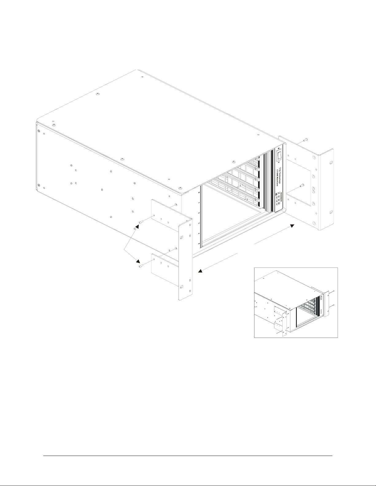
* Recessed Rack Mount Installation Shown
F
IGURE 2.2: RACK MOUNT EAR INSTALLATION DIAGRAM
Rack Mount Ears (x2)
Flush Rackmount Configu ration
CT-100B Installation 23
Page 24

RACK SLIDE INSTALLATION (20” AND 24”)
The 20” and 24” slide hardware kits (Options 63 and 64, respectively) provide standard flanges to
mount the slides into standard EIA relay racks. It should be noted that the slide flanges in the
front should be installed behind the rack’s front panel mounting rails. This will allow the rack
mounting ears to sit flush with the front of the rack. It should also be noted that although the
hardware provided in this kit will provide all the necessary components to successfully install the
CT-100B into a rack, there are many variations in how EIA relay racks are designed and
additional adapter hardware may be required to install the chassis. Please refer to the relay rack
manufacture’s catalog for additional options.
This procedure provides instructions for installing the 20” or 24” slide kits. Note that the 20” and
24” slide kits are identical except for the length of the slide units. A 20” slide kit is used when the
chassis is flush mounted and a 24” slide kit is used when the chassis is recess mounted.
REQUIRED TOOLS
1. #2 Phillips Screwdriver
2. 1/8" Flat Blade Screwdriver
PARTS LIST
VXI Technology, Inc.
QTY ITEM VTI P/N
2 Slide, Rack Mount, Steel, 20” 37-0054-020
- or -
2 Slide, Rack Mount, Steel, 24” 37-0054-024
1 Hardware Kit, Rack Mount Slide, Steel 37-0055-000
6 Screw, 8-32 x 3/8” Pan Head Phillips, Sems Zinc 37-0073-037
6 Screw, 8-32 x 1/4” Pan Head Phillips, Steel/Zinc 37-0074-025
4 Screw, 8-32 x 3/8”, F/H Undercut Phillips, Zinc 37-0115-037
2 Bracket, Slide, Front 41-0108-000
1 Bracket, Slide, Top Side 41-0131-000
1 Bracket, Slide, Bottom 41-0132-000
ASSEMBLY INSTRUCTIONS
1. Lay the chassis on a protected work surface on its long side with the voltage monitor LEDs of
the chassis facing front with the power switch toward the top.
2. If the rack mount ears were installed flush, remove the rack mount ears and install the front
slide bracket to them as shown in the assembly drawing using a flat head screw driver. If the
rack mount ears were installed recessed, simply install the slide brackets onto the ears as
shown on the following page.
3. Reinstall the rack mount ears (if necessary).
4. Install the top and bottom slide brackets using 1/4” Phillips pan head screws. Note that the
slide mounting holes should be oriented below the centerline of the chassis.
24 CT-100B Installation
Page 25
www.vxitech.com
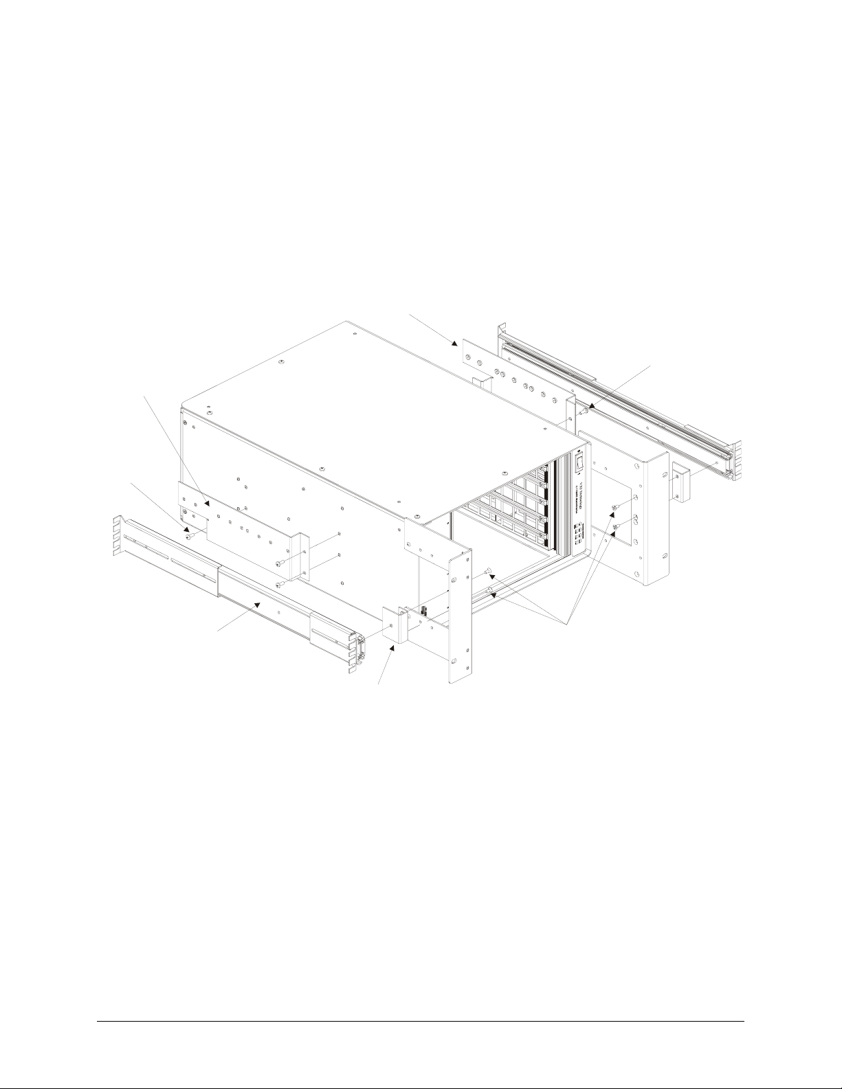
Slide Bracket, Bottom
5. Locate the slide hardware kit provided. Install the rack flanges to the slides as required by the
application using the hardware in the kit. Note that the screws are inserted from the inside of
the slides and the nuts would show on the outside.
6. Install the slides to the mounting brackets already installed on the chassis using the provided
hardware.
Slide Bracket, Top
1/4” Pan Head
Phillips Screw (x3)
1/4” Pan Head
Phillips Screw (x3)
Rack Mount Slide (20” or 24”)
Hardware Kit
3/8” Pan Head Phillips Screws (x6)
* Recessed rack slide configuration shown
3/8” Undercut Flathead
Phillips Screws (x4)
Slide Bracket, (x2) Front
FIGURE 2.3: RACK SLIDE INSTALLATION DIAGRAM
CT-100B Installation 25
Page 26

RACK MOUNT DOOR KIT INSTALLATION
The rack mount door kit (Option 60) provides the necessary hardware to install a 1/8” thick
aluminum door in front of the rack mounted chassis. This option requires that the rack mount ear
kit also be installed and configured for recessed mounting. The door may be customer modified
to hold connectors, controls, indicators and similar components.
REQUIRED TOOLS
1. #2 Phillips Screwdriver
2. 1/8" Flat Blade Screwdriver
3. 11/32" Open Ended Wrench
PARTS LIST
QTY ITEM VTI P/N
2 Slide, Rack Mount, Steel, 20" 37-0054-020
1 Hardware Kit, Rack Mount Slide, Steel 37-0055-000
6 Screw, 8-32 x 3/8" Pan Head Phillips, Sems Zinc 37-0073-037
6 Screw, 8-32 x 1/4" Pan Head Phillips, Steel/Zinc 37-0074-025
4 Screw, 8-32 x 3/8", F/H Undercut Phillips, Zinc 37-0115-037
2 Bracket, Slide, Front, 5 Slot Chassis, CT-100B 41-0108-000
1 Bracket, Slide, Top Side, CT-100B 41-0131-000
1 Bracket, Slide, Bottom, CT-100B 41-0132-000
VXI Technology, Inc.
ASSEMBLY PROCEDURE
1. Lay the chassis on a protected work surface on its long side with the voltage monitor LEDs of
the chassis facing front with the power switch toward the top.
2. Locate two rackmount (cross) braces. Install one each along the front of the flanges (one on
top and one on the bottom) using four (two ea.) #8 flathead screws. The lip along the long
edge of each brace goes toward the front and pointing inside. The braces fit over the flanges
and the screws are placed from the inside going through the flange and then into the brace.
3. Locate the front door and two hinges. Install the two hinges to the front door using four
black screws provided.
4. Locate the latch kit and install it into the door from the side where the hinges are mounted.
5. Locate the door latch bracket and install it on the rack mount ear opposite the end where the
hinges will be installed. Use the rack mount door installation diagram below as a reference.
6. Locate the four tapped holes on the front surface of the rack mount ear to which the door is to
be attached.
7. Install the door by its hinges to the rack mount ear using four black screws provided with the
option kit.
8. Test that the door opens and closes smoothly and adjust the latch as necessary to secure the
door when latched close.
26 CT-100B Installation
Page 27

www.vxitech.com
1/2” Pan Head
Phillips Screws (x2)
Front Door Stop
6-32 Hex Nuts (x2)
Rackmount Braces (x2)
3/8” Flat Head
Phillips Screws (x4)
Hinges (x2)
Front Door, Aluminum
3/8” Pan Head Black Oxide
Phillips Screws (x8)
Door Latch Kit
FIGURE 2.4: RACK DOOR INSTALLATION DIAGRAM
CT-100B Installation 27
Page 28

VXI Technology, Inc.
ACRYLIC RACK MOUNT DOOR KIT INSTALLATION
An acrylic rack mount door is offered as an alternative to the aluminum rack mount door. The kit
(Option 65) provides the necessary hardware to install a 1/8” thick acrylic door in front of the rack
mounted chassis. An installation diagram is provided on the following page for ease of assembly.
This option requires that the rack mount ear kit also be installed and configured for recessed
mounting.
REQUIRED TOOLS
1. #2 Phillips Screwdriver
2. 1/8" Flat Blade Screwdriver
3. 11/32" Open Ended Wrench
PARTS LIST
QTY ITEM VTI P/N
2 Screw, 6-32 x 1/2" Pan Head Phillips, Sems Zinc 37-0028-050
2 Nut, Hex, 6-32, Zinc/Steel 37-0030-632
1 Latch, Vise Action, Knob Style, Black 37-0065-000
2 Hinge, Adjustable Damping, Black 37-0066-000
4 Screw, 8-32 x 3/8" Pan Head Phillips, Black Oxide 37-0079-037
1 Stop, Front Door, CT-100B 41-0133-000
1 Door, Front, CT-100, Acrylic 41-0303-000
2 Brace, Rackmount, CT-100B 41-0136-000
4 Nut, Hex, 8-32, Zinc/Steel 37-0030-832
4 Washer, Split Lock, 8-32 Zinc 37-0013-008
4 Washer, Flat 8-32, Zinc 37-0012-008
4 Screw, 8-32 x 1/2" Pan Head Phillips, Black Oxide 37-0079-050
4 Screw, 8-32 x 3/8" Flat Head Phillips, Zinc 37-0080-037
ASSEMBLY PROCEDURE
1. Lay the chassis on a protected work surface on its long side with the voltage monitor LEDs of
the chassis facing front with the power switch toward the top.
2. Locate two rack mount (cross) braces. Install one each along the front of the flanges (one on
top and one on the bottom) using four (two ea.) #8 flathead screws. The lip along the long
edge of each brace goes toward the front and pointing inside. The braces fit over the flanges
and the screws are placed from the inside going through the flange and then into the brace.
3. Locate the front door and two hinges. Install the two hinges to the front door using four 1/2”
black oxide pan head screws through the holes of the hinge with the flat washer in contact
with the door and with the split lock washer between the hex nut and the flat washer.
4. Locate the latch kit and install it into the door from the side where the hinges are mounted.
5. Locate the door latch bracket and install it on the rack mount ear opposite the end where the
hinges will be installed. Use the rack mount door installation diagram below as a reference.
28 CT-100B Installation
Page 29

www.vxitech.com
6. Locate the four tapped holes on the front surface of the rack mount ear to which the door is to
be attached.
7. Install the door by its hinges to the rack mount ear using four 3/8” black pan head screws
provided with the option kit.
8. Test that the door opens and closes smoothly and adjust the latch as necessary to secure the
door when latched close.
Rack Mount Braces (x2)
3/8” Flat Head
Phillips Screws (x4)
8-32 Hex Nuts (x4)
8-32 Split Lock Washer
8-32 Flat Washer
Front Door, Acryli c
Hinges (x2)
3/8” Pan Head Black Oxide
Phillips Screws (x4)
1/2” Pan Head Black Oxide
Phillips Screws (x4)
Door Latch Kit
F
IGURE 2.5: ACRYLIC RACK DOOR INSTALLATION DIAGRAM
CT-100B Installation 29
Page 30

VXI Technology, Inc.
30 CT-100B Installation
Page 31

www.vxitech.com
OPERATION
INTRODUCTION
There are no operating instructions required for the CT-100B VXIbus chassis. After the chassis is
installed, operation is completely transparent to the operator. Just plug in the instruments then
power up the chassis. The power supply lines are monitored and displayed on the front panel to
provide user feedback of correct operation (see Figure 3-2).
SECTION 3
F
IGURE 3-1 CT-100B SIX-SLOT CHASSIS W/ INSTALLED INSTRUMENTS
CT-100B Operation 31
Page 32

VXI Technology, Inc.
VOLTAGE MONITOR
0 1
0 1
VXI Technology
CT100B Mainframe
VOLTAGE MONITOR
-2V -24V -12V -5.2V
-2V -24V -12V -5.2V
+ 5V
+ 24V + 12V + 5V
+ 5V
+ 24V + 12V + 5V
STBY
STBY
Green
Not Lit
Red
Voltage Monitor LEDs
: Within Voltage Specifications
: Under Voltage
: Over Voltage
0 1 2 3 4 5
bus
IGURE 3-2 FRONT PANEL VOLTAGE INDICATORS
F
32 CT-100B Operation
Page 33

www.vxitech.com
INDEX
#
5V STANDBY................................................................ 12
A
airflow....................................................................... 12, 15
B
backplane........................................................................ 12
backplane configuration.................................................. 12
D
DC supply voltage ..........................................................16
dimentions ......................................................................17
dynamic current .............................................................. 16
dynamic current (I
F
fuse ....................................................................... 7, 12, 19
J
jumpering........................................................................ 12
L
line frequencies............................................................... 12
M
MTTR............................................................................. 15
O
output voltage ................................................................. 16
P
peak current ....................................................................16
peak current (I
power supplies ................................................................ 12
R
rack mount ...................................................................... 21
rack mounting................................................................. 12
rack slide......................................................................... 21
rack-mount...................................................................... 13
S
specifications ...................................................... 14, 15, 16
cooling....................................................................... 15
environmental............................................................ 15
general ....................................................................... 15
power......................................................................... 16
survival ........................................................................... 15
V
voltage ............................................................................16
VXIbus ........................................................................... 12
VXIbus Version........................................................ 14, 15
)..................................................... 14
MD
) ........................................................... 14
MP
CT-100B Index 33
 Loading...