

Page 1

VXI-MXI
User Manual
October 1993 Edition
Part Number 320222-01
©
Copyright
1989, 1993
All Rights Reserved.
National Instruments Corporation.
Page 2

National Instruments Corporate Headquarters
6504 Bridge Point Parkway
Austin, TX 78730-5039
(512) 794-0100
(800) 433-3488 (toll-free U.S. and Canada)
Technical support fax: (512) 794-5678
Branch Offices:
Australia 03 879 9422, Austria 0662 435986, Belgium 02 757 00 20, Canada (Ontario) 519 622 9310,
Canada (Québec) 514 694 8521, Denmark 45 76 26 00, Finland 90 527 2321, France 1 48 65 33 70,
Germany 089 714 50 93, Italy 02 48301892, Japan 03 3788 1921, Netherlands 01720 45761, Norway 03 846866,
Spain 91 640 0085, Sweden 08 730 49 70, Switzerland 056 27 00 20, U.K. 0635 523545
Page 3

Limited Warranty
The National Instruments MXIbus boards and accessories are warranted against defects in materials and
workmanship for a period of one year from the date of shipment, as evidenced by receipts or other documentation.
National Instruments will, at its option, repair or replace equipment that proves to be defective during the warranty
period. This warranty includes parts and labor.
A Return Material Authorization (RMA) number must be obtained from the factory and clearly marked on the
outside of the package before any equipment will be accepted for warranty work. National Instruments will pay the
shipping costs of returning to the owner parts which are covered by warranty.
National Instruments believes that the information in this manual is accurate. The document has been carefully
reviewed for technical accuracy. In the event that technical or typographical errors exist, National Instruments
reserves the right to make changes to subsequent editions of this document without prior notice to holders of this
edition. The reader should consult National Instruments if errors are suspected. In no event shall National
Instruments be liable for any damages arising out of or related to this document or the information contained in it.
EXCEPT AS SPECIFIED HEREIN, NATIONAL INSTRUMENTS MAKES NO WARRANTIES, EXPRESS OR IMPLIED,
AND SPECIFICALLY DISCLAIMS ANY WARRANTY OF MERCHANTABILITY OR FITNESS FOR A PARTICULAR
PURPOSE
OF
NATIONAL INSTRUMENTS WILL NOT BE LIABLE FOR DAMAGES RESULTING FROM LOSS OF DATA, PROFITS,
USE OF PRODUCTS, OR INCIDENTAL OR CONSEQUENTIAL DAMAGES, EVEN IF ADVISED OF THE POSSIBILITY
THEREOF
whether in contract or tort, including negligence. Any action against National Instruments must be brought within
one year after the cause of action accrues. National Instruments shall not be liable for any delay in performance due
to causes beyond its reasonable control. The warranty provided herein does not cover damages, defects,
malfunctions, or service failures caused by owner's failure to follow the National Instruments installation, operation,
or maintenance instructions; owner's modification of the product; owner's abuse, misuse, or negligent acts; and
power failure or surges, fire, flood, accident, actions of third parties, or other events outside reasonable control.
. CUSTOMER'S RIGHT TO RECOVER DAMAGES CAUSED BY FAULT OR NEGLIGENCE ON THE PART
NATIONAL INSTRUMENTS SHALL BE LIMITED TO THE AMOUNT THERETOFORE PAID BY THE CUSTOMER.
. This limitation of the liability of National Instruments will apply regardless of the form of action,
Copyright
Under the copyright laws, this publication may not be reproduced or transmitted in any form, electronic or
mechanical, including photocopying, recording, storing in an information retrieval system, or translating, in whole
or in part, without the prior written consent of National Instruments Corporation.
Trademarks
Product and company names listed are trademarks or trade names of their respective companies.
Warning Regarding Medical and Clinical Use
of National Instruments Products
National Instruments products are not designed with components and testing intended to ensure a level of reliability
suitable for use in treatment and diagnosis of humans. Applications of National Instruments products involving
medical or clinical treatment can create a potential for accidental injury caused by product failure, or by errors on
the part of the user or application designer. Any use or application of National Instruments products for or involving
medical or clinical treatment must be performed by properly trained and qualified medical personnel, and all
traditional medical safeguards, equipment, and procedures that are appropriate in the particular situation to prevent
serious injury or death should always continue to be used when National Instruments products are being used.
National Instruments products are NOT intended to be a substitute for any form of established process, procedure, or
equipment used to monitor or safeguard human health and safety in medical or clinical treatment.
Page 4

FCC/DOC Radio Frequency Interference Compliance
This equipment generates and uses radio frequency energy and, if not installed and used in strict accordance with the
instructions in this manual, may cause interference to radio and television reception. This equipment has been tested
and found to comply with the following two regulatory agencies:
Federal Communications Commission
This device complies with Part 15 of the Federal Communications Commission (FCC) Rules for a Class A digital
device. Operation is subject to the following two conditions:
1. This device may not cause harmful interference in commercial environments.
2. This device must accept any interference received, including interference that may cause undesired operation.
Canadian Department of Communications
This device complies with the limits for radio noise emissions from digital apparatus set out in the Radio
Interference Regulations of the Canadian Department of Communications (DOC).
Le présent appareil numérique n'émiet pas de bruits radioélectriques dépassant les limites applicables aux appareils
numériques de classe A prescrites dans le réglement sur le brouillage radioélectrique édicté par le ministére des
communications du Canada.
Instructions to Users
These regulations are designed to provide reasonable protection against harmful interference from the equipment to
radio reception in commercial areas. Operation of this equipment in a residential area is likely to cause harmful
interference, in which case the user will be required to correct the interference at his own expense.
There is no guarantee that interference will not occur in a particular installation. However, the chances of
interference are much less if the equipment is installed and used according to this instruction manual.
If the equipment does cause interference to radio or television reception, which can be determined by turning the
equipment on and off, one or more of the following suggestions may reduce or eliminate the problem.
• Operate the equipment and the receiver on different branches of your AC electrical system.
• Move the equipment away from the receiver with which it is interfering.
• Reorient or relocate the receiver's antenna.
• Be sure that the equipment is plugged into a grounded outlet and that the grounding has not been defeated with
a cheater plug.
Notice to user: Changes or modifications not expressly approved by National Instruments could void the user's
authority to operate the equipment under the FCC Rules.
If necessary, consult National Instruments or an experienced radio/television technician for additional suggestions.
The following booklet prepared by the FCC may also be helpful: How to Identify and Resolve Radio-TV
Interference Problems. This booklet is available from the U.S. Government Printing Office, Washington, DC
20402, Stock Number 004-000-00345-4.
Page 5

Contents
About This Manual............................................................................................................... xi
Organization of This Manual ........................................................................................... xi
How to Use This Manual ................................................................................................ xii
Related Documentation................................................................................................... xii
Customer Communication .............................................................................................. xii
Chapter 1
General Information
Overview........................................................................................................................ 1-4
Front Panel Features....................................................................................................... 1-5
What Your Kit Should Contain...................................................................................... 1-6
Optional Equipment ....................................................................................................... 1-6
Unpacking ...................................................................................................................... 1-7
Chapter 2
General Description
Electrical Characteristics................................................................................................ 2-1
VMEbus Modules .......................................................................................................... 2-2
VXI-MXI Functional Description.................................................................................. 2-5
.......................................................................................................... 1-1
........................................................................................................... 2-1
Chapter 3
Configuration and Installation
Configuring the VXI-MXI............................................................................................. 3-1
The Metal Enclosure .......................................................................................... 3-4
VXIbus Slot 0..................................................................................................... 3-4
VXIbus Logical Address.................................................................................... 3-6
VMEbus Request Level ..................................................................................... 3-7
VMEbus Timeout Value .................................................................................... 3-8
VMEbus Timeout Chain Position...................................................................... 3-10
Interlocked Arbitration Mode ............................................................................ 3-13
MXIbus System Controller ................................................................................ 3-14
MXIbus System Controller Timeout.................................................................. 3-16
MXIbus Fairness Option.................................................................................... 3-17
CLK10 Source.................................................................................................... 3-18
EXT CLK SMB Input/Output................................................................ 3-20
INTX CLK10 Mapping.......................................................................... 3-20
Trigger Input Termination ................................................................................. 3-22
Reset Signal Select............................................................................................. 3-23
Installing the VXI-MXI Hardware................................................................................. 3-23
MXIbus Termination.......................................................................................... 3-24
INTX Termination ............................................................................................. 3-25
Installation Instructions...................................................................................... 3-26
Connecting the INTX Cable .............................................................................. 3-27
Connecting the MXIbus Cable........................................................................... 3-28
System Power Cycling Requirements................................................................ 3-30
VMEbus Devices in VXIbus/MXIbus Systems............................................................. 3-31
....................................................................................... 3-1
© National Instruments Corporation v VXI-MXI User Manual
Page 6

Contents
Chapter 4
Register Descriptions
Register Maps ................................................................................................................ 4-1
Register Sizes..................................................................................................... 4-1
Register Description Format .............................................................................. 4-1
Hard and Soft Reset ........................................................................................... 4-1
VXIbus Configuration Registers.................................................................................... 4-4
VXIbus ID Register ........................................................................................... 4-4
Device Type Register......................................................................................... 4-6
VXIbus Status/Control Register......................................................................... 4-7
VXIbus Extender Registers............................................................................................ 4-9
MODID Register................................................................................................ 4-9
Logical Address Window Register .................................................................... 4-10
A16 Window Map Register ............................................................................... 4-14
A24 Window Map Register ............................................................................... 4-18
A32 Window Map Register ............................................................................... 4-22
INTX Interrupt Configuration Register ............................................................. 4-26
INTX Trigger Configuration Register ............................................................... 4-27
INTX Utility Configuration Register................................................................. 4-28
Subclass Register ............................................................................................... 4-30
MXIbus Defined Registers............................................................................................. 4-31
MXIbus Status/Control Register........................................................................ 4-31
MXIbus Lock Register....................................................................................... 4-36
MXIbus IRQ Configuration Register................................................................. 4-37
Drive Triggers/Read LA Register...................................................................... 4-39
Trigger Mode Selection Register ....................................................................... 4-41
Interrupt Status/Control Register ....................................................................... 4-45
Status/ID Register .............................................................................................. 4-48
MXIbus Trigger Configuration Register............................................................ 4-49
Trigger Synchronous Acknowledge Register .................................................... 4-50
Trigger Asynchronous Acknowledge Register.................................................. 4-50
IRQ Acknowledge Registers.............................................................................. 4-51
......................................................................................................... 4-1
Chapter 5
Programming Considerations
System Configuration .................................................................................................... 5-1
Planning a VXIbus/MXIbus System Logical Address Map .............................. 5-1
Base/Size Configuration Format............................................................ 5-3
High/Low Configuration Format ........................................................... 5-5
Steps to Follow When Planning a System Logical Address Map.......... 5-5
Worksheets for Planning Your VXIbus/MXIbus Logical Address Map........... 5-13
Alternative Worksheets for Planning Your VXIbus/MXIbus Logical
Address Map ...................................................................................................... 5-18
Planning a VXIbus/MXIbus System A16 Address Map ................................... 5-21
Worksheets for Planning Your VXIbus/MXIbus A16 Address Map ................ 5-29
Multiframe RM Operation ............................................................................................. 5-35
Configuring the Logical Address Window ........................................................ 5-35
Configuring the Logical Address Window Example............................. 5-36
Configuring the A24 and A32 Addressing Windows ........................................ 5-38
System Administration and Initiation ................................................................ 5-39
VXI-MXI User Manual vi © National Instruments Corporation
........................................................................................ 5-1
Page 7

Chapter 6
Theory of Operation
VMEbus Address and Address Modifier Transceivers.................................................. 6-1
VXIbus System Controller Functions............................................................................ 6-1
VMEbus Data Transceivers ........................................................................................... 6-1
VMEbus Control Signals Transceivers.......................................................................... 6-2
VMEbus Requester and Arbiter Circuitry ..................................................................... 6-2
TTL and ECL Trigger Lines and CLK10 Circuitry....................................................... 6-2
SYSFAIL, ACFAIL, and SYSRESET........................................................................... 6-3
Interrupt Circuitry .......................................................................................................... 6-3
Parity Check and Generation ......................................................................................... 6-6
A32, A24, A16, and LA Windows................................................................................. 6-6
VXI-MXI Configuration Registers ................................................................................ 6-6
MXIbus Master Mode State Machine............................................................................ 6-6
MXIbus Slave Mode State Machine .............................................................................. 6-10
MXIbus Address/Data and Address Modifier Transceivers.......................................... 6-11
MXIbus System Controller Functions ........................................................................... 6-12
MXIbus Control Signals Transceivers........................................................................... 6-12
MXIbus Requester and Arbiter Circuitry....................................................................... 6-12
Appendix A
Specifications
........................................................................................................................ A-1
Contents
.......................................................................................................... 6-1
Appendix B
Mnemonics Key
................................................................................................................... B-1
Appendix C
VXI-MXI Component Placement
Removing the Metal Enclosure from the VXI-MXI...................................................... C-1
Removing the INTX Daughter Card from the VXI-MXI.............................................. C-3
Installing the INTX Daughter Card onto the VXI-MXI ................................................ C-4
Appendix D
Connector Descriptions
MXIbus Connector......................................................................................................... D-1
INTX Connector ............................................................................................................ D-3
..................................................................................................... D-1
Appendix E
Configuring a Two-Frame System
Configuring VXI-MXIs for a Two-Frame System ........................................................ E-1
Configuration Requirements for Two-Frame System.................................................... E-6
BTO Unit............................................................................................................ E-6
Logical Addresses.............................................................................................. E-6
CLK10 Mapping ................................................................................................ E-6
Appendix F
Customer Communication
............................................................................................... F-1
.................................................................................. C-1
................................................................................ E-1
Glossary...................................................................................................................... Glossary-1
Index .................................................................................................................................. Index-1
© National Instruments Corporation vii VXI-MXI User Manual
Page 8

Contents
Figures
Figure 1-1. VXI-MXI Interface Module ............................................................................. 1-2
Figure 1-2. VXI-MXI Interface Module with INTX Option............................................... 1-3
Figure 2-1. VXI-MXI Block Diagram................................................................................. 2-6
Figure 2-2. VXI-MXI INTX Daughter Card Option Block Diagram ................................. 2-8
Figure 3-1. VXI-MXI Parts Locator Diagram..................................................................... 3-2
Figure 3-2. VXI-MXI with INTX Parts Locator Diagram.................................................. 3-3
Figure 3-3. VXIbus Slot 0 Selection ................................................................................... 3-4
Figure 3-4. VXIbus Non-Slot 0 Selection ........................................................................... 3-5
Figure 3-5. Logical Address Selection ................................................................................ 3-7
Figure 3-6. VMEbus Requester Jumper Settings ................................................................ 3-8
Figure 3-7. VMEbus Timeout Value Selection................................................................... 3-9
Figure 3-8. VMEbus Timeout; One VXI-MXI in Mainframe ............................................ 3-10
Figure 3-9. VMEbus Timeout; Multiple VXI-MXIs in Mainframe.................................... 3-11
Figure 3-10. No VMEbus Timeout; Multiple VXI-MXIs in Mainframe.............................. 3-12
Figure 3-11. Interlocked Arbitration Mode Selection ........................................................... 3-14
Figure 3-12. MXIbus System Controller Selection............................................................... 3-15
Figure 3-13. MXIbus System Controller Timeout Value Selection...................................... 3-16
Figure 3-14. MXIbus Fair Requester Selection..................................................................... 3-17
Figure 3-15. CLK10 Source Signal Options ......................................................................... 3-19
Figure 3-16. EXT CLK SMB Input/Output Setting .............................................................. 3-20
Figure 3-17. INTX CLK10 Mapping Switches..................................................................... 3-21
Figure 3-18. Trigger Input Termination Option Settings ...................................................... 3-22
Figure 3-19. Reset Signal Selection Settings ........................................................................ 3-23
Figure 3-20. MXIbus System ................................................................................................ 3-24
Figure 3-21. MXIbus Terminating Networks........................................................................ 3-25
Figure 3-22. INTX Terminator Example............................................................................... 3-26
Figure 3-23. MXIbus Single-Ended Cable Configuration .................................................... 3-28
Figure 3-24. MXIbus Dual-Ended Cable Configuration....................................................... 3-29
Figure 4-1. VXI-MXI Register Map ................................................................................... 4-3
Figure 5-1. VXIbus/MXIbus System with Multiframe RM on a PC .................................. 5-2
Figure 5-2. VXIbus/MXIbus System with Multiframe RM in a VXIbus Mainframe......... 5-2
Figure 5-3. Base and Size Combinations ............................................................................ 5-4
Figure 5-4. Address Range Allocation for Different Size Values....................................... 5-4
Figure 5-5. Example VXIbus/MXIbus System ................................................................... 5-8
Figure 5-6. Logical Address Map Diagram for Example VXIbus/MXIbus System........... 5-9
Figure 5-7. Worksheet 1 for Example VXIbus/MXIbus System ........................................ 5-10
Figure 5-8. Worksheet 2 for Example VXIbus/MXIbus System ........................................ 5-11
Figure 5-9. Worksheet 3 for Example VXIbus/MXIbus System ........................................ 5-12
Figure 5-10. Worksheet 4 for Example VXIbus/MXIbus System ........................................ 5-12
Figure 5-11. Logical Address Map Example with Alternative Worksheet ........................... 5-20
Figure 5-12. A16 Space Allocations for all Size Values....................................................... 5-22
Figure 5-13. Example VXIbus/MXIbus System ................................................................... 5-24
Figure 5-14. Example A16 Space Address Map ................................................................... 5-25
Figure 5-15. Worksheet 1 for A16 Address Map Example................................................... 5-26
Figure 5-16. Worksheet 2 for A16 Map Example ................................................................. 5-27
Figure 5-17. Worksheet 3 for A16 Map Example ................................................................. 5-28
VXI-MXI User Manual viii © National Instruments Corporation
Page 9

Contents
Figure 6-1. Master to Slave VMEbus/MXIbus Transfers ................................................... 6-7
Figure 6-2. Deadlock Situation............................................................................................ 6-10
Figure C-1. VXI-MXI Parts Locator Diagram..................................................................... C-2
Figure C-2. VXI-MXI INTX Parts Locator Diagram (Rear View) ..................................... C-3
Figure C-3. VXI-MXI INTX Parts Locator Diagram (Front View) .................................... C-4
Figure D-1. MXIbus Connector ........................................................................................... D-1
Figure D-2. INTX Connector............................................................................................... D-3
Figure E-1. A Two-Frame VXI System............................................................................... E-1
Figure E-2. VXI-MXI in Frame A without INTX ............................................................... E-2
Figure E-3. VXI-MXI in Frame B without INTX ............................................................... E-3
Figure E-4. VXI-MXI in Frame A with INTX .................................................................... E-4
Figure E-5. VXI-MXI in Frame B with INTX .................................................................... E-5
Tables
Table 2-1. VXI-MXI VMEbus Signals.............................................................................. 2-1
Table 2-2. MXIbus Transceiver Requirements.................................................................. 2-2
Table 2-3. VXI-MXI VMEbus Compliance Levels........................................................... 2-3
Table 3-1. MXIbus System Power Cycling Requirements ................................................ 3-30
Table 4-1. VXI-MXI Register Map ................................................................................... 4-2
Table 5-1. Base and Size Combinations ............................................................................ 5-3
Table 5-2. Example VXIbus/MXIbus System Required Logical Addresses..................... 5-8
Table 5-3. Amount of A16 Space Allocated for all Size Values ....................................... 5-21
Table 5-4. Example VXIbus/MXIbus System Required A16 Space ................................. 5-25
Table 5-5. Logical Address Assignments for Example VXIbus/MXIbus System............. 5-36
Table 6-1. VXI-MXI Addresses for VMEbus Interrupt Levels......................................... 6-5
Table 6-2. VMEbus to MXIbus Address Modifier Line Map ........................................... 6-7
Table 6-3. Transfer Responses for VMEbus Address Modifiers....................................... 6-8
Table 6-4. VMEbus/MXIbus Transfer Size Comparison .................................................. 6-9
Table D-1. MXIbus Connector Signal Assignments .......................................................... D-1
Table D-2. MXIbus Signal Groupings................................................................................ D-2
Table D-3. INTX Connector Signal Assignments.............................................................. D-3
Table D-4. INTX Signal Groupings.................................................................................... D-4
© National Instruments Corporation ix VXI-MXI User Manual
Page 10

About This Manual
The VXI-MXI User Manual describes the functional, physical, and electrical aspects of the
VXI-MXI and contains information concerning its operation and programming.
Organization of This Manual
The VXI-MXI User Manual is organized as follows:
• Chapter 1, General Information, describes the VXI-MXI features, lists the contents of your
VXI-MXI kit, and explains how to unpack the VXI-MXI kit.
• Chapter 2, General Description, contains the physical and electrical specifications for the
VXI-MXI and describes the characteristics of key components.
• Chapter 3, Configuration and Installation, describes the configuration and installation of the
VXI-MXI hardware.
• Chapter 4, Register Descriptions, contains detailed descriptions of the VXI-MXI registers,
which are used to configure and control the module's operation.
• Chapter 5, Programming Considerations, explains important considerations for programming
the VXI-MXI and configuring a system using VXI-MXIs.
• Chapter 6, Theory of Operation, contains a functional overview of the VXI-MXI board and
explains the operation of each functional block making up the VXI-MXI.
• Appendix A, Specifications, lists the specifications of the VXI-MXI.
• Appendix B, Mnemonics Key, contains an alphabetical listing of all mnemonics used in this
manual.
• Appendix C, VXI-MXI Component Placement, contains information on the component
placement and describes how to remove the metal enclosure and INTX daughter card.
• Appendix D, Connector Descriptions, describes the connector pin assignments for the
MXIbus connector.
• Appendix E, Configuring a Two-Frame System, describes how to configure a system
containing two mainframes linked by VXI-MXI modules.
• Appendix F, Customer Communication, contains forms you can use to request help from
National Instruments or to comment on our products and manuals.
• The Glossary contains an alphabetical list and description of terms used in this manual,
including abbreviations, acronyms, metric prefixes, and symbols.
• The Index contains an alphabetical list of key terms and topics in this manual, including the
page where you can find each one.
© National Instruments Corporation xi VXI-MXI User Manual
Page 11

About This Manual
How to Use This Manual
If you will be installing your VXI-MXI into a system with a VXIbus Resource Manager, you
only need to read Chapters 1 through 3 of this manual. If you have more than two VXI-MXIs
extending your system, you will find useful system configuration information in Chapter 5.
Appendix E is a quick reference for users who have a system containing two mainframes linked
by VXI-MXI modules. If you are writing your own VXIbus Resource Manager routines, you
can find programming information and descriptions of the VXI-MXI hardware in Chapters 4
through 6.
Related Documentation
The following manuals contain information that you may find helpful as you read this manual:
• IEEE Standard for a Versatile Backplane Bus: VMEbus, ANSI/IEEE Standard 1014-1987
• Multisystem Extension Interface Bus Specification, Version 1.2 (part number 340007-01)
• VXIbus System Specification, Revision 1.4, VXIbus Consortium (available from National
Instruments, part number 350083-01)
Customer Communication
National Instruments wants to receive your comments on our products and manuals. We are
interested in the applications you develop with our products, and we want to help if you have
problems with them. To make it easy for you to contact us, this manual contains comment and
configuration forms for you to complete. These forms are in Appendix F, Customer
Communication, at the end of this manual.
VXI-MXI User Manual xii © National Instruments Corporation
Page 12

Chapter 1 General Information
This chapter describes the VXI-MXI features, lists the contents of your VXI-MXI kit, and
explains how to unpack the VXI-MXI kit.
The VXI-MXI interface is a C-size extended class mainframe extender for the VXIbus (VMEbus
Extensions for Instrumentation). It extends the VXIbus architecture outside a VXIbus
mainframe via the MXIbus (Multisystem Extension Interface bus). A VXIbus mainframe
equipped with a VXI-MXI can be transparently connected to other MXIbus devices such as other
VXIbus mainframes, MXIbus instruments, or MXIbus-equipped personal computers. The
VXI-MXI interface module uses address mapping to transparently translate bus cycles on the
VXIbus system bus (VMEbus) to the MXIbus and vice versa.
The VXI-MXI is housed in a metal enclosure to improve EMI performance and to provide easy
handling. Because the enclosure includes cut-outs to facilitate changes to switch and jumper
settings, it should not be necessary to remove it under most circumstances.
The VXI-MXI is available with an Interrupt and Timing Extension (INTX) daughter card option.
If you ordered this option, the INTX card is already installed on your VXI-MXI. The INTX
daughter card is a full-length daughter card that plugs into the two daughter card connectors on
the VXI-MXI. Because this manual describes the VXI-MXI with and without this option, you
can find information on the INTX card throughout this manual. Refer also to Appendix C,
VXI-MXI Component Placement, for information on removing and reinstalling the INTX
daughter card. This appendix also contains silkscreens of the VXI-MXI and the INTX card.
Figure 1-1 shows the enclosed VXI-MXI interface module without the INTX option. Figure 1-2
shows the enclosed VXI-MXI interface module with the INTX option.
© National Instruments Corporation 1-1 VXI-MXI User Manual
Page 13

General Information Chapter 1
Figure 1-1. VXI-MXI Interface Module
VXI-MXI User Manual 1-2 © National Instruments Corporation
Page 14

Chapter 1 General Information
Figure 1-2. VXI-MXI Interface Module with INTX Option
© National Instruments Corporation 1-3 VXI-MXI User Manual
Page 15

General Information Chapter 1
Overview
The VXI-MXI is an extended class Register-Based VXIbus device with optional Slot 0 capability
so that it can reside in any slot in a C-size or D-size VXIbus chassis. The VXI-MXI converts
A32, A24, A16, D32, D16, and D08(EO) VXIbus bus cycles into MXIbus bus cycles and vice
versa. The VXI-MXI has four address windows that map into and out of the VXIbus mainframe.
These four windows represent the three VMEbus address spaces (A32, A24, and A16) plus a
dedicated window for mapping the VXIbus configuration space (the upper 16 kilobytes of A16
space).
The MXIbus is a multidrop system bus that connects multiple devices at the hardware bus level
in a software-transparent manner. Multiple VXIbus mainframes with VXI-MXI interfaces can
be connected to form a single multiframe VXIbus system. An external PC with a MXIbus
interface can also be connected to a VXIbus mainframe with a VXI-MXI. This configuration
makes the PC appear to be embedded on a VXIbus module that is plugged into the VXIbus
mainframe.
Multiple MXIbus devices are tightly coupled by mapping together portions of each device's
address space and locking the internal hardware bus cycles to the MXIbus. The window address
circuitry on each MXIbus device monitors internal local bus cycles to detect bus cycles that map
across the MXIbus. Similarly, external MXIbus cycles are monitored to detect MXIbus cycles
that map into the VXIbus system. MXIbus devices can operate in parallel at full speed over their
local system bus and need to synchronize operation with another device only when addressing or
being addressed by a resource located on another MXIbus device. The MXIbus device
originating the transaction must gain ownership of both the MXIbus and the local bus in the
target MXIbus device. All hardware bus cycles are then coupled across the MXIbus and local
buses before the transfer completes.
The VXI-MXI has the following features:
• Interfaces the VXIbus to the MXIbus (32-bit Multisystem eXtension Interface bus)
• Extends VXIbus to multiple mainframes, external MXIbus-equipped instruments, and
external MXIbus-equipped personal computers (PCs)
• Allows multiple VXIbus mainframes to appear as a single VXIbus system
• Provides integrated block mode for high-performance data transfers
• Supports dynamic configuration of VXIbus devices
• Provides optional interlocked bus operation for prevention of deadlock conditions
• Includes daughter card connector scheme giving additional functionality for optional
daughter cards
• Is fully compatible with VXIbus and MXIbus specifications
• Has no restrictions on Commander/Servant hierarchy or physical location of devices
The VXI-MXI generates all the support signals required by the VMEbus:
• VMEbus System Controller functions:
– 16 MHz system clock driver
– VME bus timeout (BTO)
VXI-MXI User Manual 1-4 © National Instruments Corporation
Page 16

Chapter 1 General Information
– Data transfer bus arbiter (PRI ARBITER)
– Interrupt acknowledge daisy-chain driver
– Pushbutton system reset switch
• VMEbus master capabilities:
– Access to A16, A24, and A32 address space
– D08(EO), D16, and D32 accesses
– Release-on-Request bus requester (jumper-selectable arbitration level)
• VMEbus slave accesses:
– A16, A24, and A32 address space
– D08(EO), D16, and D32 accesses
• VXIbus Slot 0 functions:
– 10 MHz clock
– MODID register
– TTL and ECL Trigger line support
All integrated circuit drivers and receivers used on the VXI-MXI meet the requirements of both
the VMEbus specification and the MXIbus specification.
Front Panel Features
The VXI-MXI has the following front panel features:
• Three front panel LEDs
– FAILED LED indicates that the VMEbus SYSFAIL line is asserted.
– VXI ACCESS LED indicates when the VXI-MXI is accessed from the VXIbus.
– MXI ACCESS LED indicates when the VXI-MXI is accessed from the MXIbus.
• MXIbus connector
• Three SMB connectors
– Trigger input
– Trigger output
– External clock input or output (configurable)
• System reset pushbutton
• INTX connector (if your VXI-MXI includes the INTX daughter card option)
© National Instruments Corporation 1-5 VXI-MXI User Manual
Page 17

General Information Chapter 1
What Your Kit Should Contain
Your VXI-MXI kit should contain the following components:
Component Part Number
Standard VXI-MXI Interface Module 181045-01
or
Enhanced VXI-MXI Interface Module with INTX option 181045-02
VXI-MXI User Manual 320222-01
Optional Equipment
Equipment Part Number
Type M1 MXIbus Cables
Straight-point connector to straight-point connector:
– 1 m 180758-01
– 2 m 180758-02
– 4 m 180758-04
– 8 m 180758-08
– 20 m 180758-20
Type M2 MXIbus Cables
Straight-point connector to right-angle daisy-chain connector:
– 1 m 180760-01
– 2 m 180760-02
– 4 m 180760-04
– 8 m 180760-08
– 20 m 180760-20
Type M3 MXIbus Cables
Right-angle point connector to right-angle daisy-chain connector:
– 1 m 180761-01
– 2 m 180761-02
– 4 m 180761-04
– 8 m 180761-08
– 20 m 180761-20
MXIbus Terminating Pac (External) 180780-01
VXI-MXI User Manual 1-6 © National Instruments Corporation
Page 18

Chapter 1 General Information
The following optional equipment is also available and may be necessary if your VXI-MXI
includes the INTX daughter card.
Equipment Part Number
Type INTX1 Cables
Straight-point connector to straight-point connector:
– 1 m 180980-01
– 2 m 180980-02
– 4 m 180980-04
– 8 m 180980-08
– 20 m 180980-20
Type INTX2 Cables
Right-angle point connector to right-angle daisy-chain connector:
– 1 m 180982-01
– 2 m 180982-02
– 4 m 180982-04
– 8 m 180982-08
– 20 m 180982-20
Unpacking
Follow these steps when unpacking your VXI-MXI:
1. Before attempting to configure or install the VXI-MXI, inspect the shipping container and its
contents for damage. If damage appears to have been caused in shipment, file a claim with
the carrier. Retain the packing material for possible inspection and/or for reshipment.
2. Verify that the pieces contained in the package you received match the kit parts list. Do not
remove the board from its bag at this point.
3. Your VXI-MXI module is shipped packaged in an antistatic plastic bag to prevent
electrostatic damage to the module. Several components on the module can be damaged by
electrostatic discharge. To avoid such damage while handling the module, touch the plastic
bag to a metal part of your grounded VXIbus mainframe chassis before removing the module
from the bag.
4. As you remove the VXI-MXI module from its bag, be sure to handle it only by its edges.
Avoid touching any of the IC components or connectors. Inspect the module for loose
components or any other sign of damage. Notify National Instruments if the module appears
damaged in any way. Do not install a damaged module into your VXIbus mainframe.
© National Instruments Corporation 1-7 VXI-MXI User Manual
Page 19

Chapter 2 General Description
This chapter contains the physical and electrical specifications for the VXI-MXI and describes
the characteristics of key interface board components.
Electrical Characteristics
All integrated circuit drivers and receivers used on the VXI-MXI meet the requirements of the
VMEbus specification. Table 2-1 contains a list of the VMEbus signals used by the VXI-MXI
and the electrical loading presented by the circuitry on the interface board (in terms of device
types and their part numbers).
Note: Throughout this manual, an asterisk (*) following a bus signal mnemonic indicates
that the signal is active low.
Table 2-1. VXI-MXI VMEbus Signals
Driver Device Receiver Device
Bus Signals Part Number Part Number
D[31–0], A[31–1], ALS645–1 ALS645–1
AM[5–0], LWORD ALS646–1 ALS646–1
DS0*, DS1*, WRITE* F125 ALS244
AS* F125 ALS240
SYSCLK F125 –
BG[3-0]IN* – HCT273,
GAL16V8
BG[3-0]OUT* LS32 –
BBSY*, SYSFAIL*, ACFAIL* F38 ALS240
BR[3-0]*, DTACK*, BERR* F38 ALS244
SYSRESET* AS760 ALS244
IACK* F38 –
(continues)
© National Instruments Corporation 2-1 VXI-MXI User Manual
Page 20
General Description Chapter 2
Table 2-1. VXI-MXI VMEbus Signals (Continued)
Driver Device Receiver Device
Bus Signals Part Number Part Number
IACKIN* – LS540
IACKOUT* GAL20V8 –
IRQ[7-1]* AS760,
LS145 LS540
All MXIbus transceivers meet the requirements of the MXIbus specification. Table 2-2 lists the
components used.
Table 2-2. MXIbus Transceiver Requirements
Transceivers Component Designation
Data Transceivers DS3862
Control Transceivers DS3662
VMEbus Modules
The VXI-MXI has the following VMEbus modules:
• VMEbus Requester
• VMEbus Master
• VMEbus Slave
• Interrupter
• IACK Daisy-Chain Driver
When the VXI-MXI is configured as a VXIbus Slot 0 device, it also has the following VMEbus
modules:
• VMEbus Timer
• Arbiter
• System Clock Driver
VXI-MXI User Manual 2-2 © National Instruments Corporation
Page 21

Chapter 2 General Description
The VXI-MXI does not support the following VMEbus modules:
• Serial Clock Driver
• Power Monitor
Table 2-3 indicates the VXI-MXI VMEbus compliance levels.
Table 2-3. VXI-MXI VMEbus Compliance Levels
Compliance Notation Description
Bus Slave Compliance Levels
D08(O) 8-bit data path to configuration registers and
MXIbus
D16 & D08(EO) 8-bit or 16-bit data path to configuration registers or
MXIbus
D32 32-bit data path to MXIbus
A16 Responds to 16-bit short I/O addresses when
A24 Responds to 24-bit memory addresses when
A32 Responds to 32-bit memory addresses when
ADO Accommodates address-only cycles
BLT Responds to block mode transfers
RMW Can accept Read-Modify-Write cycles
DTB Arbiter Compliance Level
PRI Monitors BR3* through BR0* and drives
DTB Requester Compliance Level
ROR Release-on-Request
specified on the address modifier lines
specified on the address modifier lines
specified on the address modifier lines
BG3OUT* through BG0OUT* and BCLR*
(continues)
© National Instruments Corporation 2-3 VXI-MXI User Manual
Page 22

General Description Chapter 2
Table 2-3. VXI-MXI VMEbus Compliance Levels (Continued)
Compliance Notation Description
Bus Master Compliance Levels
D08(EO) 8-bit data path from MXIbus
D16 & D08(EO) 8-bit or 16-bit data path from MXIbus
D32 32-bit data path from MXIbus
A16 Generates 16-bit short I/O addresses when specified
by the MXIbus address modifier lines
A24 Generates 24-bit memory addresses when specified
by the MXIbus address modifier lines
A32 Generates 32-bit memory addresses when specified
by the MXIbus address modifier lines
BLT Generates block mode transfers when specified
by the MXIbus address modifier lines
RMW Can generate Read-Modify-Write cycles
Interrupter Compliance Levels
I(7-1) Can generate an interrupt request on interrupt lines
D16 & D32 Responds to 16-bit and 32-bit interrupt acknowledge
ROAK Releases its interrupt request line when its Status/ID
Interrupt Handler Compliance Levels
IH(7-1) Can generate interrupt acknowledge cycles in
D16 Generates a 16-bit interrupt acknowledge cycle in
IRQ7 through IRQ1
cycles by providing a 16-bit Status/ID byte on D00
through D15
is read during an interrupt acknowledge cycle
response to interrupt requests on IRQ7 through IRQ1
response to a VMEbus interrupt request
VXI-MXI User Manual 2-4 © National Instruments Corporation
Page 23

Chapter 2 General Description
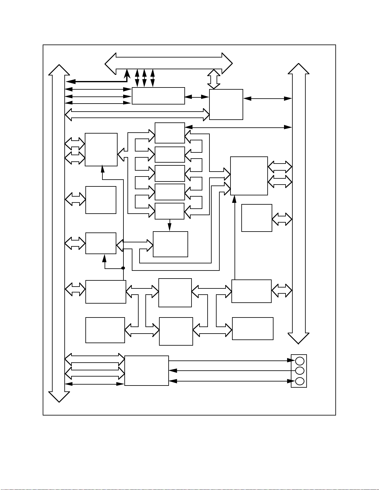
VXI-MXI Functional Description
In simplest terms, the VXI-MXI can be thought of as a bus translator that converts VXIbus
signals into appropriate MXIbus signals. From the perspective of the MXIbus, the VXI-MXI
implements a MXIbus interface to communicate with other MXIbus devices. From the
perspective of the VMEbus, the VXI-MXI is an interface to the outside world.
Figure 2-1 is a functional block diagram of the VXI-MXI. Refer to Chapter 6, Theory of
Operation for more details about the major components of the VXI-MXI.
• VMEbus Address and Address Modifiers These transceivers control the direction of the
Transceivers VMEbus address lines and latch the status of the
address lines on the falling edge of the VMEbus
address strobe.
• VXIbus System Controller Functions If the VXI-MXI is selected as the VMEbus
System Controller, this circuitry generates the
16 MHz system clock, provides the VMEbus
arbiter and the VMEbus Bus Timer Unit, and
drives the VXIbus CLK10 signal.
• VMEbus Data Transceivers These transceivers control the direction of the
VMEbus data lines and meet VMEbus
specifications for timing and signal loading.
• VMEbus Control Signals Transceivers These transceivers control the direction of the
VMEbus control signals and meet VMEbus
specifications for timing and signal loading.
• VMEbus Requester and Arbiter Circuitry This circuitry is used to request the VMEbus and
to provide the VMEbus arbiter function if the
VXI-MXI is the VMEbus System Controller.
• TTL and ECL Trigger Lines and This circuitry controls the sending and receiving
CLK10 Circuitry of the TTL and ECL Trigger lines to and from the
SMB connectors on the front panel and from
onboard registers. This logic also controls
whether the VXI-MXI receives the CLK10 signal
from another VXIbus device, or drives the signal
from an onboard 10 MHz oscillator or from an
external signal connected to the EXT CLK SMB
connector on the front panel.
• SYSFAIL, ACFAIL, and SYSRESET Through this circuitry, the VMEbus signals
SYSFAIL, ACFAIL and SYSRESET connect to
the corresponding signals on the daughter card
connections. These three signals can also be
individually enabled to generate a VMEbus
interrupt. With control bits in onboard registers,
SYSFAIL and SYSRESET can also be driven on
the VMEbus backplane.
© National Instruments Corporation 2-5 VXI-MXI User Manual
Page 24
General Description Chapter 2
Daughter Card Connection
IRQ7-1
AM5-0
A31-1
VXIbus
D31-0
SYSFAIL*
SYSRESET*
ACFAIL*
VMEbus IRQ7-1
VMEbus
Address and
Address
Modifiers
Transceivers
VXIbus
System
Controller
Functions
VMEbus
Data
Transceivers
SYSFAIL, ACFAIL,
SYSRESET Logic
Parity
Check and
Generation
A32
Window
A24
Window
A16
Window
LA
Window
VXI-MXI
Configuration
Registers
Interrupt
Circuitry
IRQ*
PAR
MXIbus
Address/Dat
a and
Address
Modifiers
Transceivers
MXIbus
System
Controller
Functions
AM4-0
AD31-0
MXIbus
VMEbus
Control Signals
Transceivers
VMEbus
Requester and
Arbiter Circuitry
TTL Trigger Lines 7-0
ECL Trigger Lines 1-0
CLK10
MXIbus
Master Mode
State
Machine
MXIbus
Slave Mode
State
Machine
TTL and ECL
Trigger Lines
and
CLK10 Circuitry
Figure 2-1. VXI-MXI Block Diagram
MXIbus
Control Signals
Transceivers
MXIbus
Requester and
Arbiter Circuitry
TRG OUT
TRG IN
EXT CLK
Front
Panel
SMBs
VXI-MXI User Manual 2-6 © National Instruments Corporation
Page 25

Chapter 2 General Description
• Interrupt Circuitry This circuitry generates and receives interrupt
requests on the VMEbus, the MXIbus, and on
boards plugged into the daughter card connectors.
Interrupt requests routed between VXIbus
mainframes can be transparently serviced by
interrupt handlers in VXIbus mainframes other
than the requester's own mainframe.
• Parity Check and Generation This circuitry checks and generates MXIbus
parity.
• A32, A24, A16 and LA Windows These address windows assign portions of the
MXIbus address space to the VXIbus mainframe
and vice versa.
• VXI-MXI Configuration Registers These registers provide all the configuration
information required by the VXI-MXI and are
accessible from both the VXIbus and the MXIbus.
• MXIbus Master Mode State Machine This state machine converts VXIbus cycles
mapped out of a MXIbus window to the MXIbus
into MXIbus cycles.
• MXIbus Slave Mode State Machine This state machine converts MXIbus cycles
mapped through a MXIbus window into the
VXIbus mainframe into VXIbus cycles.
• MXIbus Address/Data and Address These transceivers and associated circuitry control
Modifiers Transceivers the direction of the MXIbus address and data
lines. When a VXIbus transfer is mapped out to
the MXIbus, the VXIbus address/data lines are
multiplexed into the MXIbus address/data lines.
When a MXIbus transfer is mapped into the
VXIbus, the MXIbus address/data lines are
demultiplexed into separate VXIbus address and
data lines.
• MXIbus System Controller Functions If the VXI-MXI is the MXIbus System Controller,
this circuitry provides the MXIbus arbiter,
interrupt daisy-chain generation, and the MXIbus
System Controller timeout logic.
• MXIbus Control Signals Transceivers These transceivers control the direction of the
MXIbus control signals.
• MXIbus Requester and Arbiter Circuitry This circuitry is used to request the MXIbus when
a VXIbus transfer is mapped into a MXIbus
window.
• Daughter Card Connection The two daughter card connectors can be used to
add additional functionality to the VXI-MXI in
the form of plug-in daughter cards.
© National Instruments Corporation 2-7 VXI-MXI User Manual
Page 26
General Description Chapter 2
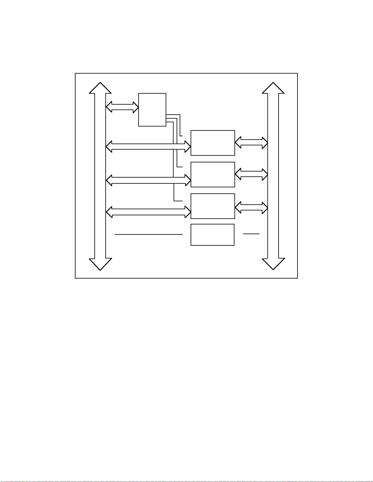
The following information applies only to VXI-MXI kits that include the INTX daughter card
option. Figure 2-2 is a block diagram of the circuitry of the INTX daughter card.
INTX
Registers
Interrupt Control
Trigger
Control
I N T X
System Resets
Control
V X I - M X I C O N N E C T I O N
CLK10 Control
Figure 2-2. VXI-MXI INTX Daughter Card Option Block Diagram
• INTX Registers The INTX card has three onboard registers that
reside in the VXI-MXI configuration space: the
INTX Interrupt Configuration Register, the INTX
Trigger Configuration Register, and the INTX
Utility Configuration Register. These registers
configure the mapping of the VMEbus interrupt
lines, the VXIbus trigger lines and the
SYSRESET, SYSFAIL, and ACFAIL lines to and
from the INTX connector. The INTX card also
drives the Extended Device Type Class field in
the VXIbus Status/Control Register when that
register is accessed on the VXI-MXI.
VXI-MXI User Manual 2-8 © National Instruments Corporation
Page 27

Chapter 2 General Description
• Interrupt Control The interrupt control logic maps the VMEbus
interrupt lines to and from the corresponding
INTX interrupt lines. In conjunction with the
VXI-MXI circuitry, the interrupt requests routed
between VXIbus mainframes through the INTX
connector can be transparently serviced by
interrupt handlers in VXIbus mainframes other
than the mainframe from which the request was
generated. This process takes advantage of
transparent MXIbus interrupt acknowledge cycles.
When an interrupt request received from across
the INTX is driven on the corresponding VMEbus
interrupt line, an interrupt handler in the receiving
VXIbus mainframe generates an interrupt
acknowledge cycle for that interrupt request. This
interrupt acknowledge cycle is transparently
converted into a MXIbus interrupt acknowledge
cycle for that interrupt request level. Similarly,
when a VMEbus interrupt line is driven out of the
VXIbus mainframe across the INTX connection,
an interrupt handler in another VXIbus mainframe
can generate an interrupt acknowledge cycle to
handle that interrupt. The VXI-MXI in the
requesting mainframe recognizes that the MXIbus
interrupt acknowledge cycle is for the request it is
driving and converts the cycle into a VMEbus
interrupt acknowledge cycle that can service the
VMEbus interrupt requester.
• Trigger Control The trigger control logic maps the VXIbus TTL
trigger lines to and from the corresponding INTX
trigger lines.
• System Resets Control The system resets control circuitry maps the
VMEbus signals SYSRESET, SYSFAIL, and
ACFAIL to the corresponding signals on the
INTX connection.
• CLK10 Control The CLK10 control circuitry routes the VMEbus
10 MHz signal to and from the INTX connection.
The configuration of the CLK10 mapping is
controlled by three switches on the INTX
daughter card. Refer to the INTX CLK10
Mapping section of Chapter 3, Configuration and
Installation, for instructions on configuring these
switches.
© National Instruments Corporation 2-9 VXI-MXI User Manual
Page 28

Chapter 3 Configuration and Installation
This chapter describes the configuration and installation of the VXI-MXI.
Configuring the VXI-MXI
Before installing the VXI-MXI in the VXIbus mainframe, configure the VXI-MXI to suit the
needs for your VXIbus system. The VXI-MXI module contains jumpers, switches, and slide
switches that you can use to configure the following options:
• VXIbus Slot 0
• VXIbus Logical Address
• VMEbus Request Level
• VMEbus Timeout Value
• VMEbus Timeout Chain Position
• Interlocked Arbitration Mode
• MXIbus System Controller
• MXIbus System Controller Timeout
• MXIbus Fairness Option
• CLK10 Source
• EXT CLK SMB Input/Output
• Trigger Input Termination
• Reset Signal Select
If your VXI-MXI module includes the INTX daughter card option, you can also configure the
following option:
• CLK10 Mapping
© National Instruments Corporation 3-1 VXI-MXI User Manual
Page 29

Configuration and Installation Chapter 3
Figure 3-1 shows the locations and factory default settings of the VXI-MXI configuration
jumpers and switches for a VXI-MXI without the INTX option.
Figure 3-1. VXI-MXI Parts Locator Diagram
VXI-MXI User Manual 3-2 © National Instruments Corporation
Page 30

Chapter 3 Configuration and Installation
Figure 3-2 shows the locations and factory default settings of the VXI-MXI configuration
jumpers and switches for a VXI-MXI with the INTX option.
Figure 3-2. VXI-MXI with INTX Parts Locator Diagram
© National Instruments Corporation 3-3 VXI-MXI User Manual
Page 31

Configuration and Installation Chapter 3
The Metal Enclosure
The VXI-MXI is housed in a metal enclosure to improve EMC performance and to provide easy
handling. Because the enclosure includes cut-outs to facilitate changes to switch and jumper
settings, it should not be necessary to remove it under normal circumstances.
Should you find it necessary to open the enclosure, remove the three screws on the top, the three
screws on the bottom, and the three screws on the right side panel of the enclosure.
VXIbus Slot 0
The VXI-MXI is shipped from the factory configured to be installed in Slot 0 of the VXIbus
mainframe. If another device is already in Slot 0, you must decide which device will be the Slot
0 device and reconfigure the other device for Non-Slot 0 use.
Warning: Do not install a device configured for Slot 0 into another slot without first
reconfiguring it for Non-Slot 0 use. Doing so could result in damage to the
Non-Slot 0 device, the VXIbus backplane, or both.
Figure 3-3 shows the default configuration settings for the VXI-MXI installed as the Slot 0
device. The position of slide switches S1 and S8 must match. For Slot 0 configuration, they
must both be in the ON position. In addition to S1 and S8, jumper block W7 and jumper blocks
W9 and W10 must be set for Slot 0 configuration. Refer to the VMEbus Timeout Chain Position
section and the CLK10 Source section later in this chapter to examine the options for these
jumper blocks.
Non-Slot 0
Slot 0
(S1 must match S8)
S1
Slot 0
(S8 must match S1)
S8
Figure 3-3. VXIbus Slot 0 Selection
Non-Slot 0
VXI-MXI User Manual 3-4 © National Instruments Corporation
Page 32

Chapter 3 Configuration and Installation
When the VXI-MXI is installed in Slot 0, it becomes the VMEbus System Controller, meaning
that it has VMEbus Data Transfer Bus Arbiter capability (PRI ARBITER) and that it drives the
16 MHz VMEbus system clock. The VMEbus Data Transfer Bus Arbiter circuitry accepts bus
requests on all four VMEbus request levels, prioritizes the requests, and grants the bus to the
highest priority requester. The VMEbus system clock is driven by an onboard 16 MHz oscillator
with a 50% ±5% duty cycle.
The VXIbus specification defines several additional functions for devices installed in the Slot 0
position. A Slot 0 device must implement a 16-bit MODID register to control and monitor the
VXIbus MODID lines. Slot 0 cards must also have 16.9 k pull-up resistors on each VXIbus
MODID line. If the card is not in Slot 0, the MODID0 line on that card must be pulled down to
ground with an 825 resistor.
The VXIbus Resource Manager (RM) identifies whether the VXI-MXI is configured as a Slot 0
device by reading the VXIbus Model Code in the Device Type Register. If the VXIbus Model
Code for the VXI-MXI is hex 00FE, the module is configured as a Slot 0 device; if the code is
hex 08FE, the module is configured as a Non-Slot 0 device.
To configure the VXI-MXI as a Non-Slot 0 device, change slide switches S1 and S8 to the OFF
positions as depicted in Figure 3-4. Remember to also change the settings of jumper block W7
and jumper blocks W9 and W10 as described later in this chapter.
Non-Slot 0
Slot 0
(S1 must match S8)
S1
Non-Slot 0
Slot 0
(S8 must match S1) S8
Figure 3-4. VXIbus Non-Slot 0 Selection
© National Instruments Corporation 3-5 VXI-MXI User Manual
Page 33

Configuration and Installation Chapter 3
VXIbus Logical Address
Each device in a VXIbus/MXIbus system is assigned a unique number between 0 and 254. This
8-bit number, called the logical address, defines the base address for the configuration registers
located on the device. With unique logical addresses, each VXIbus device in the system is
assigned 64 bytes of configuration space in the upper 16 KB of A16 space.
Some VXIbus devices have dynamically configurable logical addresses. These devices have an
initial logical address of hex FF, which indicates that they can be dynamically configured. While
the VXI-MXI does support dynamic configuration of VXIbus devices within its mainframe, it
cannot itself be dynamically configured. Therefore, do not set the logical address for the
VXI-MXI to hex FF.
The VXIbus RM has Logical Address 0 by definition. The VXI-MXI does not have VXIbus RM
capability, so do not set the logical address for the VXI-MXI to 0. If you are configuring a
multiple-mainframe VXIbus/MXIbus system, refer to Chapter 5, Programming Considerations,
for instructions on planning a VXIbus/MXIbus system logical address map. If you are
connecting only a PC with a MXIbus interface to the VXI-MXI, you should leave the logical
address at the default setting of 1. Using this setting, you can install devices with all other
possible logical addresses in the VXIbus mainframe.
An 8-bit DIP switch selects the logical address for the VXI-MXI. As shown in Figure 3-1, this
switch is labeled LOGICAL ADDRESS SWITCH on the front panel. The ON position on the DIP
switch corresponds to a logic value of 0, and the OFF position corresponds to a logic value of 1.
This switch is set at the factory to a default logical address of 1. Verify that the logical address
assigned to the VXI-MXI is not used by any other statically configured VXIbus device in your
system. Remember that logical addresses hex 0 and FF are not allowed for the VXI-MXI.
Figure 3-5 shows switch settings for logical address hex 1 and C0.
VXI-MXI User Manual 3-6 © National Instruments Corporation
Page 34

Chapter 3 Configuration and Installation
LOGICAL ADDRESS
SWITCH
OFF
1
Shown at
2
Default setting
3
of Logical Address 1
4
5
6
7
8
Push this side down for logic 0
Push this side down for logic 1
OFF ON
1 2 3 4 5 6 7 8
a. Switch Setting to Default Setting Logical Address
LOGICAL ADDRESS
SWITCH
OFF ON
1234567 8
OFF
1
Shown at
2
Default setting
3
of Logical Address 1
4
5
6
7
8
Push this side down for logic 0
Push this side down for logic 1
b. Switch Set to Logical Address hex C0
Figure 3-5. Logical Address Selection
VMEbus Request Level
The VXI-MXI uses one of the four VMEbus request levels to request use of the VMEbus Data
Transfer Bus (DTB). The VXI-MXI requests use of the DTB whenever an external MXIbus
device attempts a transfer that maps into the VXIbus mainframe.
The VXI-MXI is shipped from the factory configured to use VMEbus request level 3, as required
in the VXIbus specification. Request level 3 is the highest priority request level and request
level 0 is the lowest. You can change the VXI-MXI to use any of the other three request levels
by changing the jumper configuration on the jumper blocks labeled VMEbus Request Level on
the front panel. You may want to change request levels to change the priority of the VXI-MXI
request signal. For more information, refer to the VMEbus specification.
To change the VMEbus request level of the VXI-MXI, rearrange the jumpers on the pin arrays as
shown in Figure 3-6.
© National Instruments Corporation 3-7 VXI-MXI User Manual
Page 35

Configuration and Installation Chapter 3
•
•
•
•
•
•••
•
•
•
•
•
•
•
•
•
•
•
•
•
•
•
•
•
•
•••
•
•
•
•
•
•
•
•
•
•
•
•
•
•
•
•
•
•
•
VMEbus Request Level
a. Level 3 Requester (default)
•
•
•
•
•
•••
•
•
•
•
•
•
•
•
•
•
•
•
•
•
•
•
•
•
•
VMEbus Request Level
VMEbus Request Level
b. Level 2 Requester
•
•
•••
•
•
•
•
•
•
•
•
VMEbus Request Level
•
•
•
•
•
•
•
•
c. Level 1 Requester
d. Level 0 Requester
Figure 3-6. VMEbus Requester Jumper Settings
VMEbus Timeout Value
When a VXI-MXI is installed in a VXIbus mainframe, the VME Bus Timeout Unit (BTO)
circuitry for the VXIbus mainframe must be on the VXI-MXI. If there are multiple VXI-MXI
interfaces in a mainframe, the BTO must be enabled on one of them and they must be in adjacent
slots. In the case of multiple VXI-MXIs, it is recommended that the BTO be enabled on the
VXI-MXI that is installed in Slot 0. The BTO monitors the current bus cycle and asserts the bus
error (BERR) signal if a data transfer acknowledge (DTACK) or BERR is not received from the
selected slave within the given amount of time after data strobe (DS1 or DS0) becomes active.
Whenever a MXIbus transfer into or out of the VXI-MXI occurs, the VMEbus timeout on the
VXI-MXI is disabled and the MXIbus System Controller BTO monitors the transfer. This
VXI-MXI User Manual 3-8 © National Instruments Corporation
Page 36

Chapter 3 Configuration and Installation
configuration allows VXIbus transfers to have short bus timeout values and MXIbus transfers to
have much longer timeout values.
You can either disable the VMEbus timeout value or set it to 100, 200, or 400 µs by moving the
VME BTO Level jumper, as shown in Figure 3-7. The VMEbus timeout is disabled when a
VMEbus cycle maps out of the mainframe, initiating a MXIbus cycle. The configuration of the
VME BTO Chain Position jumper block selects how the VXIbus local bus is used to disable the
VMEbus timeout when outward MXIbus transfers occur. If another device has a BTO module,
remember to enable the BTO on the VXI-MXI and to disable the VMEbus BTO on the other
device.
W6
•
•
•
•
•
•
•
•
VME BTO Level
a. 100 µs BTO (Default Setting)
W6
•
•
•
•
•
•
•
•
VME BTO Level
100 µs
200 µs
400 µs
DISABLE
100 µs
200 µs
400 µs
DISABLE
W6
W6
•
•
•
•
•
•
•
•
VME BTO Level
b. 200 µs BTO
•
•
•
•
•
•
•
•
VME BTO Level
100 µs
200 µs
400 µs
DISABLE
100 µs
200 µs
400 µs
DISABLE
c. 400 µs BTO
d. Disable BTO
Figure 3-7. VMEbus Timeout Value Selection
© National Instruments Corporation 3-9 VXI-MXI User Manual
Page 37

Configuration and Installation Chapter 3
VMEbus Timeout Chain Position
The VME BTO Chain Position jumper block indicates the location of the VXI-MXI interface in
relation to other VXI-MXIs installed in the mainframe. If only one VXI-MXI is in the system,
set the jumper block to one of the configurations shown in Figure 3-8.
W7
•
•
•
•
•
•
•
•
•
•
a. One VXI-MXI, in Slot 0
(Default Setting)
VME BTO
Chain Position
W7
•
•
•
•
•
•
•
•
•
•
b. One VXI-MXI,
Non-Slot 0
VME BTO
Chain Position
Figure 3-8. VMEbus Timeout; One VXI-MXI in Mainframe
When you have multiple VXI-MXI modules installed in adjacent slots, the VXIbus local bus is
used to send a signal to the VXI-MXI with the VMEbus BTO to indicate that an outward
MXIbus transfer is in progress. The following figures show how to configure the VME BTO
Chain Position jumper block to select how the VXIbus local bus is used to disable the VMEbus
timeout during outward MXIbus transfers.
VXI-MXI User Manual 3-10 © National Instruments Corporation
Page 38

Chapter 3 Configuration and Installation
If the system contains more than one VXI-MXI, select which card will supply the VMEbus
timeout, and set the jumper block according to the VXI-MXI's position in relation to the adjacent
VXI-MXIs. Figure 3-9 shows four possible settings.
W7
VME BTO
Chain Position
•
•
•
•
•
•
•
•
a. Slot 0 VXI-MXI with BTO,
Multiple VXI-MXIs in Mainframe
(Suggested Configuration)
VME BTO
Chain Position
•
•
W7
•
•
•
•
•
•
•
•
•
•
b. Non-Slot 0 VXI-MXI with BTO,
the VXI-MXI Closest to Slot 0,
Multiple VXI-MXIs in Mainframe
W7
VME BTO
Chain Position
VME BTO
Chain Position
•
•
•
•
•
•
•
•
•
•
c. Non-Slot 0 VXI-MXI with BTO,
VXI-MXI Located between
T wo VXI-MXIs, Multiple
VXI-MXIs in Mainframe
•
•
•
•
•
•
d. Non-Slot 0 VXI-MXI with BTO,
the VXI-MXI Furthest from Slot 0,
Multiple VXI-MXIs in Mainframe
Figure 3-9. VMEbus Timeout; Multiple VXI-MXIs in Mainframe
© National Instruments Corporation 3-11 VXI-MXI User Manual
Page 39

Configuration and Installation Chapter 3
For the VXI-MXIs that do not supply the VMEbus timeout, set the VME BTO Chain Position
jumper block to reflect each VXI-MXI's position in relation to the adjacent VXI-MXIs. See
Figure 3-10.
W7
VME BTO
Chain Position
•
•
•
•
•
•
•
•
•
•
a. Slot 0 VXI-MXI without BTO,
Multiple VXI-MXIs in Mainframe
W7
•
VME BTO
Chain Position
•
W7
•
•
•
•
•
•
•
•
•
•
b. Non-Slot 0 VXI-MXI without BTO,
the VXI-MXI Closest to Slot 0,
Multiple VXI-MXIs in Mainframe
W7
VME BTO
Chain Position
VME BTO
Chain Position
•
•
•
•
•
•
•
•
•
•
c. Non-Slot 0 VXI-MXI without BTO,
VXI-MXI Located between
T wo VXI-MXIs, Multiple
VXI-MXIs in Mainframe
(Suggested Configuration)
d. Non-Slot 0 VXI-MXI without BTO,
the VXI-MXI Furthermost from Slot 0,
•
•
•
•
•
•
•
•
Multiple VXI-MXIs in Mainframe
Figure 3-10. No VMEbus Timeout; Multiple VXI-MXIs in Mainframe
VXI-MXI User Manual 3-12 © National Instruments Corporation
Page 40

Chapter 3 Configuration and Installation
Interlocked Arbitration Mode
Interlocked arbitration mode is an optional mode of operation in which the system performs as
one large VXIbus mainframe with only one master of the entire system (VXIbus and MXIbus) at
any given moment. This mode of operation prevents deadlocks by interlocking all arbitration in
the VXIbus/MXIbus system. Refer to Chapter 6 for a thorough discussion of interlocked
arbitration mode.
In the normal operating mode, there can be multiple masters operating simultaneously in the
VXIbus/MXIbus system. A deadlock occurs when a MXIbus master requests use of a VXIbus
resource in another VXIbus mainframe while a VXIbus master in that mainframe is in the
process of requesting a resource across the MXIbus. When this situation occurs, the VXIbus
master must give up its bus ownership to resolve the conflict. The BERR signal is used to
terminate the transfer on the VMEbus; however, devices in the VXIbus mainframe must be able
to detect a BERR caused by a deadlock condition so that they can retry the operation.
The VXI-MXI is shipped from the factory configured for normal operating mode. If MXIbus
transfers will be occurring both into and out of the mainframe and the VXIbus modules in your
system do not have the capability for handling BERR exceptions caused by deadlock conditions,
you may want to configure the VXI-MXI for interlocked arbitration mode. In this mode, no
changes will need to be made to software. However, parallel processing in separate VXIbus
mainframes is no longer possible, and system performance may be lower than in normal
operating mode.
VMEbus requesters are awarded the bus when they receive an active signal on the daisy-chained
bus grant line. Requesters closest to the Slot 0 device have higher priority, therefore, than
devices installed in slots farther from Slot 0. In addition, four bus request levels further prioritize
modules. For proper operation in interlocked arbitration mode, all VXI-MXIs should be
configured to request at bus request level 3, the factory default setting. In addition, only one
mainframe can have a requester at a higher priority than the VXI-MXIs in that mainframe. This
requester may be a Slot 0 device other than a VXI-MXI, such as a multiframe Resource
Manager. In all the other mainframes, the VXI-MXIs must be the highest priority requesters.
This means that a VXI-MXI should be installed in Slot 0 of its respective mainframe. In the case
of multiple VXI-MXIs in a single mainframe, the additional VXI-MXIs should be installed in the
slots adjacent to the Slot 0 VXI-MXI.
Note: Interlocked arbitration mode has a potential for long access times. Therefore, you
should configure bus timeouts for adequate times.
In a VXIbus/MXIbus system, you can configure some VXI-MXIs for normal operating mode and
others for interlocked arbitration mode. The VXIbus mainframes configured in interlocked
arbitration mode will be interlocked with each other and the mainframes configured for normal
operating mode can perform transfers in parallel. This type of system configuration is
recommended if you have one of the following situations:
• A VXIbus mainframe with only slave devices and no masters. Without bus masters, there is
no chance for deadlock. The VXI-MXIs in this mainframe can be configured for normal
operating mode.
• A VXIbus mainframe with both masters and slaves, but the masters communicate only with
the slaves in their mainframe. The masters never attempt transfers across the MXIbus so
there is no chance for deadlock when a MXIbus master attempts a transfer into the VXI
mainframe. The VXI-MXIs in this mainframe can be configured for normal operating mode.
© National Instruments Corporation 3-13 VXI-MXI User Manual
Page 41

Configuration and Installation Chapter 3
Select interlocked arbitration mode by changing the default setting of the slide switch from
Normal to Interlocked Bus Cycles as shown in Figure 3-11.
Interlocked Bus Cycles
S3
Normal
a. Normal Operating Mode (Default Setting)
Interlocked Bus Cycles
S3
Normal
b. Interlocked Bus Cycle Mode
Figure 3-11. Interlocked Arbitration Mode Selection
MXIbus System Controller
The MXIbus System Controller slide switch selects whether or not the VXI-MXI interface
module is the MXIbus System Controller. The MXIbus System Controller is the first device in
the MXIbus daisy-chain. The System Controller supplies the arbitration circuitry for MXIbus
arbitration, the MXIbus interrupt acknowledge daisy-chain driver, and the MXIbus bus timeout
unit. The VXI-MXI is shipped from the factory configured for non-MXIbus System Controller
operation. If the VXI-MXI is the first device in the MXIbus link, configure the VXI-MXI as the
MXIbus System Controller by changing the default setting of the slide switch from Disabled to
Enabled, as shown in Figure 3-12.
VXI-MXI User Manual 3-14 © National Instruments Corporation
Page 42

Chapter 3 Configuration and Installation
MXIbus System Controller Enabled
S4
Disabled
a. Not MXIbus System Controller
(Default Setting)
MXIbus System Controller Enabled
S4
Disabled
b. MXIbus System Controller
Figure 3-12. MXIbus System Controller Selection
© National Instruments Corporation 3-15 VXI-MXI User Manual
Page 43

Configuration and Installation Chapter 3
MXIbus System Controller Timeout
The MXIbus System Controller is also responsible for the MXIbus system timeout. The timeout
period begins when a MXIbus data strobe (DS) is received. The period stops when a MXIbus
DTACK or BERR is detected. If a timeout occurs, the MXIbus System Controller sends a
MXIbus BERR to clear the MXIbus system. On power up, this timeout is between 100 µs and
400 µs as configured by the MXI Controller BTO Level jumper array (refer to Figure 3-1 for its
location). You can extend the timeout to a value between 100 ms and 400 ms by setting the
LNGMXSCTO bit in the MXIbus Control Register. It is best to have a long MXIbus System
Controller timeout in MXIbus systems with many devices or in situations where one or more
MXIbus devices use a large amount of MXIbus bandwidth.
Figure 3-13 shows how to position the jumper array to set the MXIbus System Controller
timeout value. When the VXI-MXI is not configured to be the MXIbus System Controller, the
setting of this jumper array has no effect. Notice that when the LNGMXSCTO bit in the
MXIbus Control Register is zero, the selected timeout value is in microseconds. When the
LNGMXSCTO bit is one, the selected timeout value is in milliseconds.
MXI Controller BTO Level
W8
•
•
•
•
•
•
•
•
a. 100 µs/ms MXIbus
System Controller Timeout
(Default Setting)
MXI Controller BTO Level
W8
•
•
•
•
•
•
•
•
100 µ/ms
200 µ/ms
400 µ/ms
DISABLE
100 µ/ms
200 µ/ms
400 µ/ms
DISABLE
MXI Controller BTO Level
W8
•
•
•
•
•
•
•
•
b. 200 µs/ms MXIbus
System Controller Timeout
MXI Controller BTO Level
W8
•
•
•
•
•
•
•
•
100 µ/ms
200 µ/ms
400 µ/ms
DISABLE
100 µ/ms
200 µ/ms
400 µ/ms
DISABLE
c. 400 µs/ms MXIbus
System Controller Timeout
d. Disable MXIbus System
Controller Timeout
Figure 3-13. MXIbus System Controller Timeout Value Selection
VXI-MXI User Manual 3-16 © National Instruments Corporation
Page 44

Chapter 3 Configuration and Installation
MXIbus Fairness Option
The MXIbus fairness feature ensures that all requesting devices will be granted use of the
MXIbus. This feature prevents a high priority MXIbus device from consuming all of the
MXIbus bandwidth. If MXIbus fairness is enabled, a MXIbus master will not request the bus
until it detects that no other devices are requesting the bus. MXIbus fairness ensures that all
MXIbus masters have an equal opportunity to use the MXIbus.
The VXI-MXI factory default setting has the MXIbus fairness feature disabled. Keep this option
disabled if a device in your mainframe needs a large portion of the MXIbus bandwidth without
interruptions from lower priority requesters. In an unfair system, the order in which you connect
the MXIbus devices in the daisy-chain determines the priority of each device's MXIbus request.
MXIbus requesters closer to the MXIbus System Controller have higher priority than those
further down the MXIbus chain. The MXIbus fairness feature is controlled by the Fairness slide
switch. If you want your VXI-MXI to be a fair requester, change the slide switch from the
Disabled setting to Enabled, as shown in Figure 3-14.
Fairness Enabled
Disabled
a. Fairness Disabled
(Default Setting)
Figure 3-14. MXIbus Fair Requester Selection
S2
Fairness Enabled
S2
Disabled
b. Fairness Enabled
© National Instruments Corporation 3-17 VXI-MXI User Manual
Page 45

Configuration and Installation Chapter 3
CLK10 Source
The VXIbus specification requires that Slot 0 devices supply a clock signal, CLK10, on a
differential ECL output. The VXI-MXI can generate the CLK10 signal from an onboard
oscillator (10 MHz with a 50% ±5% duty cycle), route an external clock signal from the front
panel SMB connector labeled EXT CLK to the CLK10 signal, or receive the CLK10 signal. Use
the CLK10 Source Select jumper array to select one of these options, as shown in Figure 3-15.
The VXI-MXI is configured at the factory to be a Slot 0 device driving the CLK10 signal from
the onboard oscillator. If you are installing the VXI-MXI in a slot other than Slot 0, change the
jumper array so that the VXI-MXI is configured to receive the CLK10 signal.
If your VXI-MXI includes the INTX daughter card option, the VXI-MXI has the ability to route
the CLK10 signal from the INTX connector. If you intend to do this, remove the jumper
completely and store it in a safe place in case you need to change your system configuration at a
later date.
Warning: Configuring more than one VXIbus device to drive the CLK10 lines can
damage the VXIbus backplane, the CLK10 drivers on the VXIbus devices, or
both.
VXI-MXI User Manual 3-18 © National Instruments Corporation
Page 46

Chapter 3 Configuration and Installation
Drive CLK10 from onboard 10MHz, Slot 0
Drive CLK10 from SMB CLK10, Slot 0
Receive CLK10, Non-Slot 0
Drive CLK10 from onboard 10MHz, Slot 0
Drive CLK10 from SMB CLK10, Slot 0
Receive CLK10, Non-Slot 0
CLK10 Source
W9
a. Onboard 10 MHz
VXI-MXI Installed in Slot 0
(Default Setting)
CLK10 Source
W9
b. External Clock
VXI-MXI Installed in Slot 0
CLK10 Source
Select
W10
Select
W10
Select
•
•
•
•
•
•
•
•
•
•
•
•
•
•
•
•
•
•
•
•
•
•
•
•
Drive CLK10 from onboard 10MHz, Slot 0
Drive CLK10 from SMB CLK10, Slot 0
Receive CLK10, Non-Slot 0
VXI-MXI Not Installed in Slot 0
Drive CLK10 from onboard 10MHz, Slot 0
Drive CLK10 from SMB CLK10, Slot 0
Receive CLK10, Non-Slot 0
Figure 3-15. CLK10 Source Signal Options
W9
c. Do Not Source CLK10;
CLK10 Source
W9
d. Source CLK10 from INTX
VXI-MXI Installed in Slot 0
W10
Select
W10
•
•
•
•
•
•
•
•
•
•
•
•
•
•
•
•
•
•
•
•
•
•
•
•
© National Instruments Corporation 3-19 VXI-MXI User Manual
Page 47

Configuration and Installation Chapter 3
EXT CLK SMB Input/Output
If you want to have synchronized CLK10 signals in multiple VXIbus mainframes, you can
connect the CLK10 signals of the two mainframes together using the EXT CLK SMB connectors
on the front panel of the VXI-MXI. One mainframe should source the CLK10 signal to the SMB
connection. The other device receives the CLK10 signal from the SMB connection and drives it
on the VXIbus CLK10 lines. This device must be installed in Slot 0 so that it can drive the
VXIbus CLK10 signal. For this option, set the CLK10 Source Select jumpers to select an
external clock as shown in Figure 3-15(b).
Slide switch S6 sets whether the EXT CLK SMB is used as an input to receive a CLK10 signal
to drive on the VXIbus, or as an output to source the CLK10 signal to another VXIbus
mainframe. Figure 3-16 shows the two settings of slide switch S6.
S6
CLK10 out SMBCLK10 in from SMB
a. Drive EXT CLK
(Default Setting)
S6
CLK10 out SMBCLK10 in from SMB
b. Receive EXT CLK
Figure 3-16. EXT CLK SMB Input/Output Setting
INTX CLK10 Mapping
If your VXI-MXI includes the INTX daughter card option, you can use the INTX CLK10 Routing
switches to route the CLK10 signal to or from the INTX connector. The INTX daughter card is
shipped from the factory with the CLK10 mapping function disabled. Refer to Figure 3-2 to
view the location of the three slide switches used to configure the INTX CLK10 mapping.
Figure 3-17 shows how to set these switches to (a) disable CLK10 mapping, (b) enable CLK10
to map out of the mainframe through the INTX connector, or (c) enable CLK10 into the
mainframe from the INTX connector.
VXI-MXI User Manual 3-20 © National Instruments Corporation
Page 48

Chapter 3 Configuration and Installation
W2
Drive CLK10 from INTX CLK10, Slot 0
(W9 and W10 must be removed)
Do Not Drive CLK10
from INTX CLK10
W3
W1
Receive CLK10 from INTX
Drive CLK10 out INTX
W1
Receive CLK10 from INTX
Drive CLK10 out INTX
INTX CLK10 Routing
a. CLK10 Mapping Disabled (Default Setting)
Drive CLK10 from INTX CLK10, Slot 0
(W9 and W10 must be removed)
Do Not Drive CLK10
from INTX CLK10
INTX CLK10 Routing
b. CLK10 Mapped out of a Mainframe
W2
W3
W2
Drive CLK10 from INTX CLK10, Slot 0
(W9 and W10 must be removed)
Do Not Drive CLK10
from INTX CLK10
W3
W1
Receive CLK10 from INTX
Drive CLK10 out INTX
INTX CLK10 Routing
c. CLK10 Mapped into Mainframe
Figure 3-17. INTX CLK10 Mapping Switches
© National Instruments Corporation 3-21 VXI-MXI User Manual
Page 49

Configuration and Installation Chapter 3
The VXI-MXI must be installed in Slot 0 if you want to route the INTX CLK10 signal to the
VXIbus CLK10 signal. The CLK10 Source Select jumpers on the VXI-MXI must be set to
configure the VXI-MXI to receive the CLK10 because the INTX daughter card will now be
sourcing the clock signal. You can configure the VXI-MXI to be installed in any slot when the
INTX CLK10 Routing switches are enabled to map the VXIbus CLK10 signal to the INTX
connector.
Warning: Configuring more than one VXIbus device to drive the CLK10 lines or
configuring both the VXI-MXI and the INTX daughter card to drive CLK10
can damage the VXIbus backplane, the CLK10 drivers on the VXIbus devices,
or both.
Trigger Input Termination
The Trigger Input SMB connector can be terminated to 50 ohms by changing the position of
slide switch S5. See Figure 3-18.
50Ω Termination
50Ω Termination
Figure 3-18. Trigger Input Termination Option Settings
None
S5
a. Trigger Input SMB not Terminated
to 50Ω (Default Setting)
None
S5
a. Trigger Input SMB Terminated to 50Ω
VXI-MXI User Manual 3-22 © National Instruments Corporation
Page 50

Chapter 3 Configuration and Installation
Reset Signal Select
The VXI-MXI generates a 200 ms active low pulse both on power-up and when you press the
pushbutton system reset switch on the front panel. Using the Reset Signal Select slide switch,
you can route the pulse to either VMEbus signal ACFAIL* or SYSRESET*. See Figure 3-19.
Reset Signal Select
S7
ACFAIL*
SYSRESET*
a. SYSRESET* Asserted (Default Setting)
Reset Signal Select
S7
ACFAIL*
SYSRESET*
b. ACFAIL* Asserted
Figure 3-19. Reset Signal Selection Settings
Installing the VXI-MXI Hardware
The VXI-MXI is a VXIbus extender device; it has no onboard intelligence or memory. For the
VXI-MXI to perform as a MXIbus master, a device with VMEbus master capability must be
installed in the VXIbus mainframe. For the VXI-MXI to perform as a MXIbus slave in A16,
A24, or A32 space, a slave VMEbus device with resources in those address spaces must be
installed in the VXIbus mainframe.
Warning: The VXI-MXI is shipped from the factory configured to be installed into Slot 0
of your VXIbus mainframe. Installing your VXI-MXI into any slot other than
Slot 0 without changing its default configuration can damage the VXI-MXI, the
VXIbus backplane, or both.
If a device is already installed in Slot 0, reconfigure that device and install it in another slot, or
reconfigure your VXI-MXI for Non-Slot 0 use. Do not install a device configured for Slot 0 into
another slot without first reconfiguring it for Non-Slot 0 use. Remember that the VXI-MXI must
have the VMEbus BTO. If another device is providing the VMEbus BTO function, disable its
BTO before installing the VXI-MXI.
© National Instruments Corporation 3-23 VXI-MXI User Manual
Page 51

Configuration and Installation Chapter 3
MXIbus Termination
The MXIbus is a matched impedance bus and requires termination networks at the first and last
device in the MXIbus daisy-chain. These terminations minimize reflections caused by
impedance discontinuities at the ends of the cables. These termination networks are located at
the end device's MXIbus connectors and can be either external self-contained modules or internal
plug-in resistor packages. The VXI-MXI comes with terminating resistors installed. If you
prefer, you can replace them with external resistor packages for easy system reconfiguration.
Figure 3-20 shows an example of a daisy-chained MXIbus system, including terminators.
PC/AT
MXIbus System
Controller
Upstream
Terminator
62-pin MXIbus Connectors
VXI
Mainframe
VXI-MXI
MXIbus Cable
Downstream
Terminator
VXI
Mainframe
VXI-MXIVXI-MXI
VXI
Mainframe
VXI
Mainframe
VXI-MXI
Figure 3-20. MXIbus System
The VXI-MXI uses the TERMPWR connection on the MXIbus connector as the power source
for external MXIbus termination networks. TERMPWR is protected by a fuse that limits the
maximum current that can be drawn to 2A. The fuse is soldered on the module and is not user
replaceable.
Note: TERMPWR is not intended to provide power to any other device.
The VXI-MXI is shipped from the factory with terminating SIP resistor networks installed. If
the VXI-MXI will be the first or last device in the MXIbus daisy-chain and external terminating
VXI-MXI User Manual 3-24 © National Instruments Corporation
Page 52

Chapter 3 Configuration and Installation
networks are not used, you should leave these internal terminators in place. If the VXI-MXI is
not going to be an end device, or if you will be using external terminators, remove the
terminating resistor networks from their sockets and store them in a safe place in case the
MXIbus system changes.
Figure 3-21 shows the position of the six MXIbus terminating networks. All six MXIbus
networks must be either installed or removed from their sockets. Figure 3-21 also shows the
INTX terminating networks for VXI-MXIs that include the INTX daughter card option.
Figure 3-21. MXIbus Terminating Networks
INTX Termination
If your VXI-MXI includes the INTX daughter card option, you must follow much the same
procedure for termination as for the MXIbus terminators. The INTX bus requires termination
networks at the first and last devices in the INTX chain. These terminations minimize reflections
caused by impedance discontinuities at the ends of the cables and bias the signal lines to their
unasserted state when they are not driven. The INTX daughter card comes with terminating
resistors installed, as shown in Figure 3-21 along with the MXIbus termination resistors.
© National Instruments Corporation 3-25 VXI-MXI User Manual
Page 53

Configuration and Installation Chapter 3
If the daughter card will be the first or last device in the INTX chain (irrespective of the
VXI-MXI's position in the MXIbus chain), you should leave these terminators in place. If the
daughter card is not going to be an end device, remove all four terminating resistor networks
from their sockets. Store them in a safe place in case your system configuration changes. Figure
3-22 shows an example of a daisy-chained MXIbus and INTX system, including terminators.
Upstream
MXIbus
PC/AT
Terminator
VXI-MXIVXI-MXI
VXI
Mainframe
MXIbus System
Controller
MXIbus Cable
62-pin MXIbus Connectors
VXI
Mainframe
VXI-MXI
44-pin INTX
Connectors
Figure 3-22. INTX Terminator Example
Downstream
MXIbus
Terminator
INTX Terminators
VXI
Mainframe
VXI
Mainframe
VXI-MXI
INTX Terminators
Installation Instructions
Verify the following configuration considerations before installing the VXI-MXI:
• If installing the VXI-MXI in a slot other than Slot 0, verify that you have changed the
settings of the two VXIbus Slot 0 slide switches, the VME BTO Chain Position jumper, and
the CLK10 Source Select jumpers.
• Multiple VXI-MXIs must be installed in adjacent slots with proper VME BTO Chain Position
jumper settings, and the VMEbus BTO must be enabled on one of them.
VXI-MXI User Manual 3-26 © National Instruments Corporation
Page 54

Chapter 3 Configuration and Installation
• If interlocked mode is used, the VXI-MXIs must be the highest priority VMEbus requesters
in their mainframe. However, one, and only one, mainframe in the MXIbus link can have a
higher priority VMEbus requester than its VXI-MXIs.
• The first and last MXIbus devices in the MXIbus link must be terminated.
• No two devices in your VXIbus/MXIbus system can have the same logical address.
After you verify the termination networks, switches, and jumpers, record all settings on the
VXI-MXI Hardware and Software Configuration Form in Appendix F, Customer
Communication. You are now ready to install the VXI-MXI. Following are general instructions
for installing your VXI-MXI in your VXIbus mainframe. Consult the user manual or technical
reference manual of your VXIbus mainframe for specific instructions and warnings.
1. Remove power from the mainframe.
2. Remove or open any doors or covers blocking access to the mainframe slots.
3. If the VXI-MXI will be installed in a D-size mainframe, install a support designed for
installing C-size cards in D-size mainframes.
4. Insert the VXI-MXI into the slot of the mainframe by aligning the top and bottom of the card
with the card guides inside the mainframe. Slowly push the VXI-MXI straight into the slot
until it seats in the backplane receptacles. The front panel of the VXI-MXI should be even
with the front panel of the mainframe.
5. Tighten the retaining screws on the top and bottom edges of the front panel.
6. Check installation.
7. Connect MXIbus and SMB cables as required.
8. Replace or close any doors or covers to the mainframe.
9. Restore power to the mainframe.
Connecting the INTX Cable
For VXI-MXIs with the INTX daughter card option, you must use special INTX cables for
routing the additional VMEbus and VXIbus signals to other frames. The INTX cable provides
either a straight point to point link (National Instruments part number 180980-XX where XX is
the length in meters) or a single connector to dual connector link (National Instruments part
number 180982-XX, where XX is the length in meters), which gives you the ability to connect
more than two devices together.
Notice that while the MXIbus is a prioritized daisy-chain, INTX signals are bused to every
device and no priority exists. Like the MXIbus, however, INTX cables must be connected in a
daisy-chain fashion to prevent impedance discontinuities from stubs that are created in a startype configuration.
Secure the INTX cable(s) on the back of the INTX connector using the captive screw elements to
ensure that the cable(s) will not accidentally become disconnected.
© National Instruments Corporation 3-27 VXI-MXI User Manual
Page 55

Configuration and Installation Chapter 3
Connecting the MXIbus Cable
MXIbus devices are daisy-chained together with MXIbus cables. Dual-ended cables are
polarized and require proper connection to function properly. The VXI-MXI uses a shielded
62-pin high-density D-subminiature device connector specified in the MXIbus specification.
When properly configured, MXIbus cables will dress down and away from the VXIbus
mainframe. Ensure that the proper cable ends are connected to the intended devices. See
Figure 3-20.
If your VXI-MXI is the first or last device in the MXIbus and you choose to use an external
termination network, install it on the VXI-MXI connector before attaching the MXIbus cable.
Be sure to press the terminator firmly in place and use the captive screw elements to secure the
terminator in place.
If your cable has a single connector on each end of the cable (National Instruments part number
180758-XX, where XX is the length in meters), it is suitable for connecting two MXIbus devices
together. This cable is nonpolarized and can be installed with either end connected to either
device. Connect one end of the cable to the MXIbus System Controller. Connect the other end
of the cable to the second device. Figure 3-23 shows an AT-MXI serving as the MXIbus System
Controller connected to a VXI-MXI.
Figure 3-23. MXIbus Single-Ended Cable Configuration
VXI-MXI User Manual 3-28 © National Instruments Corporation
Page 56

Chapter 3 Configuration and Installation
If your MXIbus cable has a single connector on one end and a dual-ended connector on the other
end (National Instruments part number 180760-XX or 180761-XX, where XX is the length in
meters), you can create a MXIbus system that consists of more than two devices. A MXIbus
system is defined as the set of devices physically connected by individual MXIbus cable links.
These devices form a daisy-chain in which the relative priority of a device within that chain is
determined by its proximity to the first device in the MXIbus system, the MXIbus System
Controller. Devices closer to the MXIbus System Controller have a higher priority than others in
the daisy-chain. Refer to Figure 3-20 for an example of a MXIbus system.
Begin establishing the system by connecting the end of the cable with the single connector to the
MXIbus System Controller and the end of the cable with the dual-ended connectors to the next
device in the MXIbus link. If your system contains more than two devices, connect the single
connector of the next cable to the back of the dual-ended connector that you connected to the
second MXIbus device. Connect the dual-connector end to the next device. Continue in this
manner until you have all devices in your system connected.
Note: A MXIbus system may contain no more than eight daisy-chained devices and must
have a total cable distance not exceeding 20 meters.
Secure the MXIbus cable(s) on the back of the MXIbus connector (or terminating network) using
the captive screw elements to ensure that the cable(s) will not accidentally become disconnected.
Figure 3-24 shows an AT-MXI serving as the MXIbus System Controller connected with the
single connector end of the cable, and a VXI-MXI connected with the dual-ended connector.
Figure 3-24. MXIbus Dual-Ended Cable Configuration
© National Instruments Corporation 3-29 VXI-MXI User Manual
Page 57

Configuration and Installation Chapter 3
In a properly configured MXIbus system, the first and last devices in the daisy-chain each have
only one cable connected to their device connector. MXIbus devices that are neither the first nor
the last device in the daisy-chain have two (and only two) MXIbus cables attached to their device
connector.
System Power Cycling Requirements
A distributed architecture such as MXIbus does not have a common power bus or reset signal to
ensure that all devices within the extended system are initialized at the same time. Therefore,
powering-on a device after other devices in the system have already received power and become
functional may cause unintended bus activity due to the power-up state of that device. This bus
activity could result in a powered, functional MXIbus device making an attempt to respond. If
this response initiates bus arbitration, for example, the arbitration mechanism could become hung
while waiting for a nonexistent master to assume control of the bus.
To guard against this type of bus activity, you should keep in mind that two types of systems
exist with respect to power cycling. The first of these is one in which power is supplied to all
devices at roughly the same time as is the case for a system with a master power switch. In such
a system, proper operation is guaranteed if the last device to reach 5V does so within roughly
half of a second of the first device to reach 5V. The second type of system is one in which power
is applied to each MXIbus device separately. In this type of system, you must power-on devices
starting with the device at the end of the MXIbus link opposite the MXIbus System Controller
and progress towards the MXIbus System Controller. The MXIbus System Controller should be
the last device on the MXIbus link to receive power. Conversely, when removing system power,
you should power-down the device farthest from the MXIbus System Controller last so that the
termination resistors on the end device ensure that the MXIbus lines remain unasserted
throughout the power-down sequence.
When shutting down a system, you must ensure that all devices that could be adversely affected
by unintended bus cycles or interrupts have their windows and interrupt mapping disabled. The
VXI-MXI itself will not be affected during power-down; however, there may be devices in the
same frame as the VXI-MXI that could be affected.
Table 3-1 summarizes MXIbus system power cycling requirements.
Table 3-1. MXIbus System Power Cycling Requirements
System Type Power-On Requirements Power-Off Requirements
Master Power
Switch
All devices must receive power
within 0.5 seconds of each other.
Disable all A24 and A32 inward
mapping to devices that could be
adversely affected by an
unintended access. Disable all
mapping of interrupts.
Distributed Power-on devices along the
MXIbus link beginning with the
non-MXIbus System Controller
end of the MXIbus link. Make
sure the MXIbus System
Controller is the last to receive
power.
Power-off devices in opposite
order of power-on sequence
(power off MXIbus System
Controller first). Disable all A24
and A32 inward mapping to
devices that could be adversely
affected by an unintended access.
Disable all mapping of interrupts.
VXI-MXI User Manual 3-30 © National Instruments Corporation
Page 58

Chapter 3 Configuration and Installation
Keep in mind that a system can contain only one device acting as the VXIbus Resource Manager
(RM). It is important that the RM be run only after all other devices in the system have been
powered on. Because many RMs execute automatically upon power-up, you must be sure when
working with a distributed system to power-on the device containing the RM last. This implies
that any VXI-MXIs in that frame must be the MXIbus System Controllers for their respective
MXIbus systems to keep the preceding power-on procedures for individual MXIbus systems.
VMEbus Devices in VXIbus/MXIbus Systems
If you have VMEbus devices installed in your VXIbus system, pay special attention to how the
A16 resources used by the VMEbus cards are configured. The VXIbus specification has
reserved the upper 16 KB of A16 space for configuration registers on VXIbus devices. During
system initialization, the system Resource Manager scans the upper 16 KB of A16 searching for
VXIbus devices. Ensure that VMEbus devices are not mistaken for VXIbus devices.
If possible, you should configure the A16 resources for your VMEbus boards in the lower 48 KB
(0000 through BFFF hex) of A16 space, so as to not interfere with VXIbus configuration space.
The logical address window is then used for mapping configuration space for VXIbus devices,
while the A16 window is used for mapping configuration space for VMEbus devices. If you
must configure any of the VMEbus module's A16 resources in the upper 16 KB (C000 through
FFFF hex) of A16 space, you need to indicate to the system Resource Manager that there are
non-VXIbus foreign devices installed. Be careful not to configure any static VXIbus logical
addresses in the portions of A16 space occupied by the VMEbus devices.
© National Instruments Corporation 3-31 VXI-MXI User Manual
Page 59

Chapter 4 Register Descriptions
This chapter contains detailed information on the use of the VXI-MXI registers, which are used
to configure and control the module's operation. All of these configuration registers are
accessible from the VMEbus (in the VXIbus configuration space) and from the MXIbus. If you
are not writing your own multiframe Resource Manager routines, you can skip over this chapter.
Register Maps
The register map for the VXI-MXI configuration registers is shown in Table 4-1 and Figure 4-1.
The table gives the register name, the register address, the size of the register in bits, and the type
of the register (read only, write only, or read/write). The base address for the VXI-MXI
configuration space in A16 space is equal to the VXIbus logical address assigned to the
VXI-MXI shifted left six times and ORed with hex C000.
Register Sizes
The VMEbus supports three different transfer sizes for read/write operations: 8-bit, 16-bit, or
32-bit. Table 4-1 shows the size of the registers on the VXI-MXI. All 16-bit registers can be
accessed using 8-bit read/write operations.
Register Description Format
Each register bit map shows a diagram of the register with the most significant bit (bit 15 for a
16-bit register, bit 7 for an 8-bit register) shown on the left, and the least significant bit (bit 0)
shown on the right. A square is used to represent each bit. Each bit is labeled with a name inside
its square. An asterisk (*) after the bit name indicates that the signal is active low. An asterisk is
equivalent to an overbar.
Hard and Soft Reset
Each register description indicates whether the bits are cleared by a hard and/or soft reset. A
hard reset occurs when the mainframe is powered on and when the VMEbus SYSRESET signal
is active. A hard reset clears all the registers on the VXI-MXI. A soft reset occurs when the
RESET bit in the VXIbus Control Register is set. A soft reset clears signals that are asserted by
bits in the configuration registers but does not clear configuration information stored in the
configuration registers.
© National Instruments Corporation 4-1 VXI-MXI User Manual
Page 60

Register Descriptions Chapter 4
Table 4-1. VXI-MXI Register Map
Register Name Offset from Base Type Size
Address (Hex)
VXIbus ID Register 0 Read Only 16-bit
Device Type Register 2 Read Only 16-bit
VXIbus Status/Control Register 4 Read/Write 16-bit
MODID Register 8 Read/Write 16-bit
Logical Address Window Register A Read/Write 16-bit
A16 Window Map Register C Read/Write 16-bit
A24 Window Map Register E Read/Write 16-bit
A32 Window Map Register 10 Read/Write 16-bit
INTX Interrupt Configuration * 12 Read/Write 16-bit
INTX Trigger Configuration * 14 Read/Write 16-bit
INTX Utility Configuration * 18 Read/Write 16-bit
Subclass Register 1E Read Only 16-bit
MXIbus Status/Control Register 20 Read/Write 16-bit
MXIbus Lock Register 22 Read/Write 16-bit
MXIbus IRQ Configuration Register 24 Read/Write 16-bit
Drive Triggers/Read LA Register 26 Read/Write 16-bit
Trigger Mode Selection Register 28 Read/Write 16-bit
Interrupt Status/Control Register 2A Read/Write 16-bit
Status/ID Register 2C Read/Write 16-bit
MXIbus Trigger Configuration Register 2E Read/Write 16-bit
Trigger Sync. Acknowledge Register 34 Write Only 8-bit
Trigger Async. Acknowledge Register 36 Write Only 8-bit
Interrupt Acknowledge for IRQ1 32 Read Only 16-bit
Interrupt Acknowledge for IRQ2 34 Read Only 16-bit
Interrupt Acknowledge for IRQ3 36 Read Only 16-bit
Interrupt Acknowledge for IRQ4 38 Read Only 16-bit
Interrupt Acknowledge for IRQ5 3A Read Only 16-bit
Interrupt Acknowledge for IRQ6 3C Read Only 16-bit
Interrupt Acknowledge for IRQ7 3E Read Only 16-bit
* The three INTX registers at offsets 12, 14, and 18 are only available on VXI-MXIs with the
INTX daughter card option. On VXI-MXIs without the INTX option, the entire range
between offsets 12 and 1C (inclusive) is VXI-MXI Reserved Space.
VXI-MXI User Manual 4-2 © National Instruments Corporation
Page 61

Chapter 4 Register Descriptions
Offset from Base
Logical Address
VXI-MXI
Defined
Registers
3E
3C
3A
38
36
34
32
30
2E
2C
2A
28
26
24
22
20
1E
Interrupt Acknowledge 7
Interrupt Acknowledge 6
Interrupt Acknowledge 5
Interrupt Acknowledge 4
Interrupt Ack 3 / Trig Async Ack
Interrupt Ack 2 / Trig Sync Ack
Interrupt Acknowledge 1
VXI-MXI Reserved
MXIbus Trigger Configuration
Status / ID
Interrupt Status / Control
Trigger Mode Register
Drive Triggers / Read LA
MXIbus IRQ Configuration
MXIbus Lock Register
MXIbus Status / Control
Subclass Register
1C
1A
VXI-MXI Reserved
VXIbus
Extender
Registers
Basic VXI
Configuration
Registers
Figure 4-1. VXI-MXI Register Map
18
16
14
12
10
0E
0C
0A
08
06
04
02
00
INTX Utility Configuration
VXI-MXI Reserved
INTX Trigger Configuration
INTX Interrupt Configuration
A32 Window Map Register
A24 Window Map Register
A16 Window Map Register
Logical Address Window
MODID Register
Reserved
VXIbus Status / Control
Device Type
VXIbus ID Register
16-bit Words
© National Instruments Corporation 4-3 VXI-MXI User Manual
Page 62

Register Descriptions Chapter 4
VXIbus Configuration Registers
These registers are defined by the VXIbus specification for all VXIbus devices.
VXIbus ID Register
VXIbus Address: Base Address + 0 (hex)
Attributes: Read Only
15 14 13 12 11 10 9
0
1
DEVCLASS
ADDR MANID
11 11
8
76 54321 0
0111111 0
1
R
1
This register provides information about this device and its configuration. The bits in this
register are configured in hardware as shown above. Hard and soft resets have no effect on this
register.
Bit Mnemonic Description
15-14r DEVCLASS Device Class Bits
These bits indicate the device class of the VXIbus device as
follows:
00 = Memory
01 = Extended
10 = Message-Based
11 = Register-Based
The VXI-MXI is an extended device defined by National
Instruments; therefore, these bits are configured in hardware as
binary 01.
13-12r ADDR Address Space Bits
These bits indicate the address spaces in which the VXIbus device
has operational registers as follows:
00 = A16/A24
01 = A16/A32
10 = Reserved
11 = A16 Only
The VXI-MXI has operational registers in A16 only; therefore,
these bits are configured in hardware as binary 11.
VXI-MXI User Manual 4-4 © National Instruments Corporation
Page 63

Chapter 4 Register Descriptions
11-0r MANID Manufacturer ID Bits
This number uniquely identifies the manufacturer of the VXIbus
device. These bits are configured in hardware as hex FF6, the
VXIbus manufacturer ID number assigned to National Instruments.
© National Instruments Corporation 4-5 VXI-MXI User Manual
Page 64

Register Descriptions Chapter 4
Device Type Register
VXIbus Address: Base Address + 2 (hex)
Attributes: Read Only
15 14 13 12 11 10 9
0
0
1/0 0 1 1
8
MODEL
76 54321 0
1000011 0
1
1
R
This register indicates how much VMEbus memory is required by this VXIbus device, and
identifies this device with a manufacturer's unique model code. The bits in this register are set in
hardware to the values shown above. Hard and soft resets have no effect on this register.
Bit Mnemonic Description
15-0r MODEL Model Code Bits
These bits contain a unique number assigned to this device by the
manufacturer to identify this device. Model codes between 0-FF
are assigned to Slot 0 devices. When the VXI-MXI is in Slot 0, bit
11 is 0 and its model code is hex 00FE. When the VXI-MXI is not
in Slot 0, bit 11 is 1 and its model code is hex 08FE.
VXI-MXI User Manual 4-6 © National Instruments Corporation
Page 65

Chapter 4 Register Descriptions
E
N
VXIbus Status/Control Register
VXIbus Address: Base Address + 4 (hex)
Attributes: Read/Write
15 14 13 12 11 10 9
1 MODID* 1 ACCDIR
0
7
00000
0
654321
VERSIO
00 0000
EDTYP
RDY PASS
0
1
0 RESET
8
0
RESET
R
W
R
W
This register provides status information about this VXIbus device and provides a bit to force the
VXI-MXI into a Soft Reset state. The RESET bit is cleared on a hard reset. Hard and soft resets
have no effect on the other bits on this register.
Bit Mnemonic Description
15r/w, 1 Reserved Bits
14-10w,
9r/w, 8w, These bits are reserved and read back as ones. Write a zero when
7-2w, 1r/w writing to these bits.
14r MODID* MODID Line Status Bit
This bit is zero when the device is selected by the MODID line,
and one when the device is not selected by the MODID line. This
bit is read only.
13-10r EDTYPE Extended Device Type Class Bits
These bits are driven low by an optional daughter card installed on
the two 96-pin daughter card connectors. They identify the
daughter card and its capabilities. When a daughter card is not
installed, these bits are all ones. The INTX daughter card has been
assigned extended device type class hex E; therefore, when the
VXI-MXI includes this option, these bits are hex E. These bits are
read only.
8r ACCDIR Access Direction Bit
When this bit is one, the current access to the Status register
originated from a device on the MXIbus. When this bit is zero, the
current access to the Status register originated from a device on the
VMEbus. This bit is read only.
© National Instruments Corporation 4-7 VXI-MXI User Manual
Page 66

Register Descriptions Chapter 4
7-4r VERSION VXI-MXI Version Number Bits
These bits specify the revision version number of the VXI-MXI
according the table below. These bits are read only.
Version Number VXI-MXI Revision
Hex D Revision D
Hex C Revision E
Hex B Revision F
Hex A Revision G
3r RDY Ready Bit
This bit is set to one in hardware to indicate that the device is ready
to execute its full functionality. This bit is read only.
2r PASS Passed Bit
This bit is set to one in hardware to indicate that the device is
functional. This bit is read only.
0r/w RESET Reset Bit
When this bit is set, the VXI-MXI is forced into the Soft Reset
state. When this bit is cleared, the VXI-MXI is in the normal
operation state. This bit is readable and is cleared on a hard reset.
VXI-MXI User Manual 4-8 © National Instruments Corporation
Page 67

Chapter 4 Register Descriptions
VXIbus Extender Registers
These registers are defined for VXIbus extender devices.
MODID Register
VXIbus Address: Base Address + 8 (hex)
Attributes: Read/Write
15 14 13 12 11 10 9
0 0 OUTEN MODID12 MODID11 MODID10 MODID9 MODID8
7 65432
MODID7 MODID6 MODID5 MODID4 MODID3 MODID2
1
MODID1
8
0
MODID0
R/W
R/W
This register provides control and status of the MODID lines when the VXI-MXI is installed in
Slot 0.
Bit Mnemonic Description
15-14r/w 0 Reserved Bits
These bits are reserved and read back as zeros. Write a zero when
writing to these bits.
13r/w OUTEN MODID Output Enable Bits
When this bit is set, the VXI-MXI is enabled to drive the MODID
lines. When this bit is cleared, the MODID drivers are disabled.
This bit should only be set when the VXI-MXI is in Slot 0. This
bit is cleared on both hard and soft resets.
12-0r/w MODID[12-0] MODID Drive Bits
If the OUTEN bit is set, setting one of these bits drives the
corresponding MODID line high, and clearing the bit drives the
line low. Independent of OUTEN, reading these bits always
returns the current status of the corresponding MODID lines. Hard
and soft resets have no effect on these bits.
© National Instruments Corporation 4-9 VXI-MXI User Manual
Page 68

Register Descriptions Chapter 4
Logical Address Window Register
VXIbus Address: Base Address + A (hex)
Attributes: Read/Write
This register defines the range of logical addresses that are mapped into and out of the VXI-MXI
through the MXIbus. This register defines a configuration window in the upper 16 KB of A16
space. These bits are cleared on a hard reset.
The CMODE bit in the MXIbus Control Register selects the format of this register. If the
CMODE bit is 0 (default), a Base/Size window comparison is used to determine the range of
addresses in the window. If the CMODE bit is set, an upper and lower bound is used to
determine the range of addresses in the window.
The Logical Address Window Register has the following format when the CMODE bit is
cleared:
15 14 13 12 11 10 9
0 LAEN LADIR 1 1 LASIZE2 LASIZE1
0
7 65432
LABASE7 LABASE6 LABASE5 LABASE4 LABASE3 LABASE2
LAEN
LADIR 0 0 LASIZE2 LASIZE1 LASIZE0
Bit Mnemonic Description
15r/w 0 Reserved Bit
This bit is reserved and reads back as zero. Write a zero when
writing to these bits.
14r/w LAEN Logical Address Window Enable Bit
When this bit is set, the logical address mapping window is
enabled. When this bit is cleared, the logical address mapping
window is disabled except for the logical address of this device.
Access to the VXI-MXI's own configuration space is always
enabled.
1
LABASE1
8
LASIZE0
0
LABASE0
R
W
R/W
13r/w LADIR Logical Address Window Direction Bit
When this bit is set, the logical address window applies to MXIbus
cycles that are mapped into VXIbus cycles (inward cycles). When
this bit is cleared, the logical address window applies to VXIbus
cycles that are mapped out into MXIbus cycles (outward cycles).
The complement of the defined range is mapped in the opposite
direction.
VXI-MXI User Manual 4-10 © National Instruments Corporation
Page 69

Chapter 4 Register Descriptions
LAEN LADIR Window Applies to
0 X Disabled
10
VXI cycles to MXI cycles
1 MXI cycles to VXI cycles
12-11r/w 1 Reserved Bits
These bits are reserved and read back as ones. Write a zero when
writing to these bits.
10-8r/w LASIZE[2-0] Logical Address Window Size Bits
This 3-bit number specifies the number of significant address bits
in the LABASE field that are compared when determining if an
address is in the logical address window. The number of logical
addresses in the window is 2
8-i
where i is the value of LASIZE
[2-0]. Because i can range from 0 to 7, the minimum size of a
logical address window is 2, and the maximum size is 256.
7-0r/w LABASE[7-0] Logical Address Window Base Address Bits
These bits, in conjunction with the LASIZE bits, define the base
address of the Logical Address window for the VXI-MXI. The
LASIZE bits indicate the number of LABASE bits that are most
significant. LABASE7 is the most significant, and LABASE0 is
the least. The LABASE bits that are not significant can be
replaced with zeros to provide the base address of the logical
address window.
Logical Address Window Example:
LABASE LASIZE Logical Addresses in Window
any value 0 00 to FF
00 1 00 to 7F
08 2 00 to 3F
18 3 00 to 1F
3F 4 30 to 3F
55 5 50 to 57
88 6 88 to 8B
CC 7 CC to CD
AA 0 00 to FF
AA 1 80 to FF
AA 2 80 to BF
AA 3 A0 to BF
AA 4 A0 to AF
AA 5 A8 to AF
AA 6 A8 to AB
AA 7 AA to AB
© National Instruments Corporation 4-11 VXI-MXI User Manual
Page 70

Register Descriptions Chapter 4
The Logical Address Window Register has the following format when the CMODE bit is set:
15 14 13 12 11 10 9 8
LAHIGH7 LAHIGH6 LAHIGH5 LAHIGH4 LAHIGH3 LAHIGH2
7 65432
LALOW7 LALOW6 LALOW5 LALOW4 LALOW3 LALOW2
LAHIGH1
1
LALOW1
LAHIGH0
0
LALOW0
R/W
R/W
Bit Mnemonic Description
15-8r/w LAHIGH[7-0] Logical Address Window Upper Bound Bits
These bits define the upper limit of the range of MXIbus logical
addresses that map into the VXIbus.
7-0r/w LALOW[7-0] Logical Address Window Lower Bound Bits
These bits define the lower limit of the range of MXIbus logical
addresses that map into the VXIbus.
This register defines the range of MXIbus logical addresses that map into the VXIbus where that
range is:
LAHIGH > range LALOW
The VXIbus logical addresses mapped out of the VXI-MXI are the inverse of this range, that is,
MXIbus logical addresses greater than or equal to the LAHIGH value or less than the LALOW
value.
To map a consecutive range of VXIbus logical addresses out of the VXI-MXI, the lower bound
of the range must be placed in the LAHIGH field and the upper bound in the LALOW field. In
this case, the range of VXIbus logical addresses mapped out of the VXI-MXI is:
LALOW > range LAHIGH
The MXIbus logical addresses mapped into the VXIbus are the inverse of this range, that is,
VXIbus logical addresses greater than or equal to the LALOW value or less than the LAHIGH
value.
The window is disabled whenever LAHIGH = LALOW = 0. All VXIbus logical addresses are
mapped out to the MXIbus when:
FF (hex) (LAHIGH = LALOW) 80 (hex)
All MXIbus logical addresses are mapped into the VXIbus when:
7F (hex) (LAHIGH = LALOW) > 0
VXI-MXI User Manual 4-12 © National Instruments Corporation
Page 71

Chapter 4 Register Descriptions
To accommodate 8-bit devices that write to this register, the window is not enabled until the
lower byte of the register is written. Therefore, 8-bit devices should write the upper byte first,
then the lower byte.
© National Instruments Corporation 4-13 VXI-MXI User Manual
Page 72

Register Descriptions Chapter 4
A16 Window Map Register
VXIbus Address: Base Address + C (hex)
Attributes: Read/Write
This register defines the range of addresses in the lower 48 KB of A16 space that is mapped into
and out of the VXI-MXI through the MXIbus. Earlier versions of the VXI-MXI required the
A16 window to be statically configured with a DIP switch. Now the A16 window can only be
dynamically configured with this register. These bits are cleared on a hard reset.
The CMODE bit in the MXIbus Control Register selects the format of this register. If the
CMODE bit is 0 (default), a Base/Size window comparison is used to determine the range of
addresses in the window. If the CMODE bit is set, an upper and lower bound is used to
determine the range of addresses in the window.
The A16 Window Map Register has the following format when the CMODE bit is cleared:
15 14 13 12 11 10 9
0
0
7
A16BASE7 A16BASE6 A16BASE5A16BASE4 A16BASE3A16BASE2A16BASE1 A16BASE00R/W
A16EN A16DIR 1 1 A16SIZE2 A16SIZE1 A16SIZE0
A16EN
654321
A16DIR A16SIZE2 A16SIZE1
00
8
A16SIZE0
R
W
Bit Mnemonic Description
15r/w 0 Reserved Bit
This bit is reserved and reads back as zero. Write a zero when
writing to these bits.
14r/w A16EN A16 Window Enable Bit
When this bit is set, the A16 mapping window is enabled. When
this bit is cleared, the A16 mapping window is disabled.
13r/w A16DIR A16 Window Direction Bit
When this bit is set, the A16 window applies to MXIbus cycles that
are mapped into VXIbus cycles (inward cycles). When this bit is
cleared, the A16 window applies to VXIbus cycles that are mapped
out into MXIbus cycles (outward cycles). The complement of the
defined range is mapped in the opposite direction.
VXI-MXI User Manual 4-14 © National Instruments Corporation
Page 73

Chapter 4 Register Descriptions
A16EN A16DIR Window Applies to
0 X Disabled
10
1 MXI cycles to VXI cycles
12-11r/w 1 Reserved Bits
These bits are reserved and read back as ones. Write a zero when
writing to these bits.
10-8r/w A16SIZE[2-0] A16 Window Size Bits
This 3-bit number specifies the number of significant address bits
in the A16BASE field that are compared when determining if an
address is in the A16 window. The number of A16 addresses in
the window is 256 * 2
8-i
where i is the value of A16SIZE[2-0].
The minimum size of an A16 window is 512 B and the maximum
size is 48 KB (A16SIZE = 0).
7-0r/w A16BASE[7-0] A16 Window Base Address Bits
These bits, in conjunction with the A16SIZE bits, define the base
address of the A16 window for the VXI-MXI. The A16SIZE bits
indicate the number of A16BASE bits that are most significant.
A16BASE7 is the most significant and A16BASE0 is the least.
The A16BASE bits that are not significant can be replaced with
zeros to provide the base address of the A16 window.
VXI cycles to MXI cycles
A16 Window Example:
A16BASE A16SIZE A16 Addresses in Window
any value 0 0000 to BFFF
3F 1 0000 to 7FFF
80 2 8000 to BFFF
26 3 2000 to 3FFF
49 4 4000 to 4FFF
98 5 9800 to 9FFF
42 6 4000 to 43FF
A1 7 A000 to A1FF
55 0 0000 to BFFF
55 1 0000 to 7FFF
55 2 4000 to 7FFF
55 3 4000 to 5FFF
55 4 5000 to 5FFF
55 5 5000 to 57FF
55 6 5400 to 57FF
55 7 5400 to 55FF
© National Instruments Corporation 4-15 VXI-MXI User Manual
Page 74

Register Descriptions Chapter 4
The A16 Window Map Register has the following format when the CMODE bit is set:
15 14 13 12 11 10 9 8
A16HIGH7 A16HIGH6 A16HIGH5 A16HIGH4 A16HIGH3 A16HIGH2
7 65432
A16LOW7 A16LOW6 A16LOW5 A16LOW4 A16LOW3 A16LOW2
A16HIGH1
1
A16LOW1
A16HIGH0
0
A16LOW0
R/W
R/W
Bit Mnemonic Description
15-8r/w A16HIGH[7-0] A16 Window Upper Bound Bits
These bits define the upper limit of the range of MXIbus A16
addresses that map into the VXIbus.
7-0r/w A16LOW[7-0] A16 Window Lower Bound Bits
These bits define the lower limit of the range of MXIbus A16
addresses that map into the VXIbus.
This register defines the range of MXIbus A16 addresses that map into the VXIbus where that
range is:
A16HIGH > range A16LOW
The VXIbus A16 addresses mapped out of the VXI-MXI are the inverse of this range, that is,
MXIbus A16 addresses greater than or equal to the A16HIGH value or less than the A16LOW
value.
To map a consecutive range of VXIbus A16 addresses out of the VXI-MXI, the lower bound of
the range must be placed in the A16HIGH field and the upper bound in the A16LOW field. In
this case, the range of VXIbus A16 addresses mapped out of the VXI-MXI is:
A16LOW > range A16HIGH
The MXIbus A16 addresses mapped into the VXIbus are the inverse of this range, that is,
VXIbus A16 addresses greater than or equal to the A16LOW value or less than the A16HIGH
value.
The window is disabled whenever A16HIGH = A16LOW = 0. All VXIbus A16 addresses are
mapped out to the MXIbus when:
FF (hex) (A16HIGH = A16LOW) 80 (hex)
All MXIbus A16 addresses are mapped into the VXIbus when:
7F (hex) (A16HIGH = A16LOW) > 0
VXI-MXI User Manual 4-16 © National Instruments Corporation
Page 75

Chapter 4 Register Descriptions
To accommodate 8-bit devices that write to this register, the window is not enabled until the
lower byte of the register is written. Therefore, 8-bit devices should write the upper byte first,
then the lower byte.
© National Instruments Corporation 4-17 VXI-MXI User Manual
Page 76

Register Descriptions Chapter 4
A24 Window Map Register
VXIbus Address: Base Address + E (hex)
Attributes: Read/Write
This register defines the range of addresses in A24 space that are mapped into and out of the
VXI-MXI through the MXIbus. These bits are cleared on a hard reset.
The CMODE bit in the MXIbus Control Register selects the format of this register. If the
CMODE bit is 0 (default), a Base/Size window comparison is used to determine the range of
addresses in the window. If the CMODE bit is set, an upper and lower bound is used to
determine the range of addresses in the window.
The A24 Window Map Register has the following format when the CMODE bit is cleared:
15 14 13 12 11 10 9
0 A24EN A24DIR 1 1 A24SIZE2 A24SIZE1 A24SIZE0
0
7
A24BASE7 A24BASE6 A24BASE5 A24BASE4 A24BASE3 A24BASE2 A24BASE1 A24BASE00R/W
A24EN
654321
A24DIR
0
0 A24SIZE2 A24SIZE1 A24SIZE0
8
R
W
Bit Mnemonic Description
15r/w 0 Reserved Bit
This bit is reserved and reads back as zero. Write a zero when
writing to these bits.
14r/w A24EN A24 Window Enable Bit
When this bit is set, the A24 mapping window is enabled. When
this bit is cleared, the A24 mapping window is disabled.
13r/w A24DIR A24 Window Direction Bit
When this bit is set, the A24 window applies to MXIbus cycles that
are mapped into VXIbus cycles (inward cycles). When this bit is
cleared, the A24 window applies to VXIbus cycles that are mapped
out into MXIbus cycles (outward cycles). The complement of the
defined range is mapped in the opposite direction.
VXI-MXI User Manual 4-18 © National Instruments Corporation
Page 77

Chapter 4 Register Descriptions
A24EN A24DIR Window Applies to
0 X Disabled
10
1 MXI cycles to VXI cycles
12-11r/w 1 Reserved Bits
These bits are reserved and read back as ones. Write a zero when
writing to these bits.
10-8r/w A24SIZE[2-0] A24 Window Size Bits
This 3-bit number specifies the number of significant address bits
in the A24BASE field that are compared when determining if an
address is in the A24 window. The number of A24 addresses in
the window is 65536 * 2
8-i
where i is the value of A24SIZE[2-0].
The minimum size of an A24 window is 128 KB, and the
maximum size is 16 MB.
7-0r/w A24BASE[7-0] A24 Window Base Address Bits
These bits, in conjunction with the A24SIZE bits, define the base
address of the A24 window for the VXI-MXI. The A24SIZE bits
indicate the number of A24BASE bits that are most significant.
A24BASE7 is the most significant and A24BASE0 is the least.
The A24BASE bits that are not significant can be replaced with
zeros to provide the base address of the A24 window.
VXI cycles to MXI cycles
A24 Window Example:
A24BASE A24SIZE A24 Addresses in Window
any value 0 000000 to FFFFFF
4E 1 000000 to 7FFFFF
A7 2 800000 to BFFFFF
35 3 200000 to 3FFFFF
6C 4 600000 to 6FFFFF
81 5 800000 to 87FFFF
B4 6 B40000 to B7FFFF
02 7 020000 to 03FFFF
00 0 000000 to FFFFFF
00 1 000000 to 7FFFFF
00 2 000000 to 3FFFFF
00 3 000000 to 1FFFFF
00 4 000000 to 0FFFFF
00 5 000000 to 07FFFF
00 6 000000 to 03FFFF
00 7 000000 to 01FFFF
© National Instruments Corporation 4-19 VXI-MXI User Manual
Page 78

Register Descriptions Chapter 4
The A24 Window Map Register has the following format when the CMODE bit is set:
15 14 13 12 11 10 9 8
A24HIGH7 A24HIGH6 A24HIGH5 A24HIGH4 A24HIGH3 A24HIGH2
7 65432
A24LOW7 A24LOW6 A24LOW5 A24LOW4 A24LOW3 A24LOW2
A24HIGH1
1
A24LOW1
A24HIGH0
0
A24LOW0
R/W
R/W
Bit Mnemonic Description
15-8r/w A24HIGH[7-0] A24 Window Upper Bound
These bits define the upper limit of the range of MXIbus A24
addresses that map into the VXIbus.
7-0r/w A24LOW[7-0] A24 Window Lower Bound
These bits define the lower limit of the range of MXIbus A24
addresses that map into the VXIbus.
This register defines the range of MXIbus A24 addresses that map into the VXIbus where that
range is:
A24HIGH > range A24LOW
The VXIbus A24 addresses mapped out of the VXI-MXI are the inverse of this range, that is,
MXIbus A24 addresses greater than or equal to the A24HIGH value or less than the A24LOW
value.
To map a consecutive range of VXIbus A24 addresses out of the VXI-MXI, the lower bound of
the range must be placed in the A24HIGH field and the upper bound in the A24LOW field. In
this case the range of VXIbus A24 addresses mapped out of the VXI-MXI is:
A24LOW > range A24HIGH
The MXIbus A24 addresses mapped into the VXIbus are the inverse of this range, that is,
VXIbus A24 addresses greater than or equal to the A24LOW value or less than the A24HIGH
value.
The window is disabled whenever A24HIGH = A24LOW = 0. All VXIbus A24 addresses are
mapped out to the MXIbus when:
FF (hex) (A24HIGH = A24LOW) 80 (hex)
All MXIbus A24 addresses are mapped into the VXIbus when:
7F (hex) (A24HIGH = A24LOW) > 0
VXI-MXI User Manual 4-20 © National Instruments Corporation
Page 79

Chapter 4 Register Descriptions
To accommodate 8-bit devices that write to this register, the window is not enabled until the
lower byte of the register is written. Therefore, 8-bit devices should write the upper byte first,
then the lower byte.
© National Instruments Corporation 4-21 VXI-MXI User Manual
Page 80

Register Descriptions Chapter 4
A32 Window Map Register
VXIbus Address: Base Address + 10 (hex)
Attributes: Read/Write
This register defines the range of addresses in A32 space that are mapped into and out of the
VXI-MXI through the MXIbus. These bits are cleared on a hard reset.
The CMODE bit in the MXIbus Control Register selects the format of this register. If the
CMODE bit is 0 (default), a Base/Size window comparison is used to determine the range of
addresses in the window. If the CMODE bit is set, an upper and lower bound is used to
determine the range of addresses in the window.
The A32 Window Map Register has the following format when the CMODE bit is cleared:
15 14 13 12 11 10 9
0 A32EN A32DIR 1 1 A32SIZE2 A32SIZE1 A32SIZE0
0
7
A32BASE7 A32BASE6 A32BASE5 A32BASE4 A32BASE3 A32BASE2 A32BASE1 A32BASE00R/W
A32EN
654321
A32DIR 0 0 A32SIZE2 A32SIZE1 A32SIZE0
8
R
W
Bit Mnemonic Description
15r/w 0 Reserved Bit
This bit is reserved and reads back as zero. Write a zero when
writing to these bits.
14r/w A32EN A32 Window Enable Bit
When this bit is set, the A32 mapping window is enabled. When
this bit is cleared, the A32 mapping window is disabled.
13r/w A32DIR A32 Window Direction Bit
When this bit is set, the A32 window applies to MXIbus cycles that
are mapped into VXIbus cycles (inward cycles). When this bit is
cleared, the A32 window applies to VXIbus cycles that are mapped
out into MXIbus cycles (outward cycles). The complement of the
defined range is mapped in the opposite direction.
VXI-MXI User Manual 4-22 © National Instruments Corporation
Page 81

Chapter 4 Register Descriptions
A32EN A32DIR Window Applies to
0 X Disabled
10
1 MXI cycles to VXI cycles
12-11r/w 1 Reserved Bits
These bits are reserved and read back as ones. Write a zero when
writing to these bits.
10-8r/w A32SIZE[2-0] A32 Window Size Bits
This 3-bit number specifies the number of significant address bits
in the A32BASE field that are compared when determining if an
address is in the A32 window. The number of A32 addresses in
the window is 16,777,216 * 2
8-i
A32SIZE[2-0]. The minimum size of an A32 window is 32 MB,
and the maximum size is 4 GB.
7-0r/w A32BASE[7-0] A32 Window Base Address Bits
These bits, in conjunction with the A32SIZE bits, define the base
address of the A32 window for the VXI-MXI. The A32SIZE bits
indicate the number of A32BASE bits that are most significant.
A32BASE7 is the most significant and A32BASE0 is the least.
The A32BASE bits that are not significant can be replaced with
zeros to provide the base address of the A32 window.
VXI cycles to MXI cycles
where i is the value of
A32 Window Example:
A32BASE A32SIZE A32 Addresses in Window
any value 0 00000000 to FFFFFFFF
C8 1 80000000 to FFFFFFFF
3E 2 00000000 to 3FFFFFFF
49 3 40000000 to 5FFFFFFF
9A 4 90000000 to 9FFFFFFF
21 5 20000000 to 27FFFFFF
75 6 74000000 to 77FFFFFF
19 7 18000000 to 19FFFFFF
FF 0 00000000 to FFFFFFFF
FF 1 80000000 to FFFFFFFF
FF 2 C0000000 to FFFFFFFF
FF 3 E0000000 to FFFFFFFF
FF 4 F0000000 to FFFFFFFF
FF 5 F8000000 to FFFFFFFF
FF 6 FC000000 to FFFFFFFF
FF 7 FE000000 to FFFFFFFF
© National Instruments Corporation 4-23 VXI-MXI User Manual
Page 82

Register Descriptions Chapter 4
The A32 Window Map Register has the following format when the CMODE bit is set:
15 14 13 12 11 10 9 8
A32HIGH7 A32HIGH6 A32HIGH5 A32HIGH4 A32HIGH3 A32HIGH2
7 65432
A32LOW7 A32LOW6 A32LOW5 A32LOW4 A32LOW3 A32LOW2
A32HIGH1
1
A32LOW1
A32HIGH0
0
A32LOW0
R/W
R/W
Bit Mnemonic Description
15-8r/w A32HIGH[7-0] A32 Window Upper Bound
These bits define the upper limit of the range of MXIbus A32
addresses that map into the VXIbus.
7-0r/w A32LOW[7-0] A32 Window Lower Bound
These bits define the lower limit of the range of MXIbus A32
addresses that map into the VXIbus.
This register defines the range of MXIbus A32 addresses that map into the VXIbus where that
range is:
A32HIGH > range A32LOW
The VXIbus A32 addresses mapped out of the VXI-MXI are the inverse of this range, that is,
MXIbus A32 addresses greater than or equal to the A32HIGH value or less than the A32LOW
value.
To map a consecutive range of VXIbus A32 addresses out of the VXI-MXI, the lower bound of
the range must be placed in the A32HIGH field and the upper bound in the A32LOW field. In
this case, the range of VXIbus A32 addresses mapped out of the VXI-MXI is:
A32LOW > range A32HIGH
The MXIbus A32 addresses mapped into the VXIbus are the inverse of this range, that is,
VXIbus A32 addresses greater than or equal to the A32LOW value or less than the A32HIGH
value.
The window is disabled whenever A32HIGH = A32LOW = 0. All VXIbus A32 addresses are
mapped out to the MXIbus when:
FF (hex) (A32HIGH = A32LOW) 80 (hex)
All MXIbus A32 addresses are mapped into the VXIbus when:
7F (hex) (A32HIGH = A32LOW) > 0
VXI-MXI User Manual 4-24 © National Instruments Corporation
Page 83

Chapter 4 Register Descriptions
To accommodate 8-bit devices that write to this register, the window is not enabled until the
lower byte of the register is written. Therefore, 8-bit devices should write the upper byte first,
then the lower byte.
© National Instruments Corporation 4-25 VXI-MXI User Manual
Page 84

Register Descriptions Chapter 4
INTX Interrupt Configuration Register (on VXI-MXIs with INTX only)
VXIbus Address: Base Address + 12 (hex)
Attributes: Read/Write
15 14 13 12 11 10 9
0
7 65432
0 EINT7DIR EINT6DIR EINT5DIR EINT4DIR EINT3DIR EINT2DIR EINT1DIR
EINT7EN EINT6EN EINT5EN EINT4EN EINT3EN EINT2EN EINT1EN
1
8
R/W
0
R/W
This register on the INTX daughter card is used to configure the mapping of the seven VMEbus
interrupts lines to and from the seven INTX interrupt lines.
Bit Mnemonic Description
15,7r/w 0 Zero Bits
These bits read back as zero to indicate that this register contains
the extended interrupt mapping bits. Writes to these bits have no
effect.
14-8r/w EINT[7-1]EN Extended Interrupt Enable Bits
Setting these bits individually enables the corresponding VMEbus
IRQ lines to drive or receive the corresponding INTX interrupt
line. The corresponding EINTDIR bits select whether the INTX
interrupt line is driven or received by the VMEbus IRQ line.
These bits are cleared on a hard reset.
6-0r/w EINT[7-1]DIR Extended Interrupt Direction Bits
When the corresponding EINTxEN bits are clear, these bits have
no meaning. When the corresponding EINTxEN bits are set, these
bits control the routing of the INTX IRQ signals. When
EINTxDIR is clear, the corresponding VMEbus IRQ line drives the
INTX IRQ line. If the EINTxDIR bit is set, the INTX IRQ line
drives the corresponding VMEbus IRQ line.
EINTxEN EINTxDIR Routing
0 X Disabled
10
VME IRQ X drives INTX IRQ
1 INTX IRQ drives VME IRQ X
VXI-MXI User Manual 4-26 © National Instruments Corporation
Page 85

Chapter 4 Register Descriptions
INTX Trigger Configuration Register (on VXI-MXIs with INTX only)
VXIbus Address: Base Address + 14 (hex)
Attributes: Read/Write
15 14 13 12 11 10 9
ETRG7EN ETRG6EN ETRG5EN ETRG4EN ETRG3EN ETRG2EN ETRG1EN ETRG0EN
7 65432
ETRG7DIR ETRG6DIR ETRG5DIR ETRG4DIR ETRG3DIR ETRG2DIR ETRG1DIR ETRG0DIR
1
8
R/W
0
R/W
This register on the INTX daughter card is used to configure the mapping of the eight VXIbus
TTL trigger lines to and from the eight INTX trigger lines.
Bit Mnemonic Description
15-8r/w ETRG[7-0]EN Extended Trigger Enable Bits
Setting these bits individually enables the corresponding VXIbus
TTL trigger lines to be mapped to the corresponding INTX trigger
lines, as specified by the corresponding ETRGxDIR bits. Clearing
these bits disables the mapping of the trigger lines to the INTX
trigger lines. These bits are cleared on a hard reset.
7-0r/w ETRG[7-0]DIR Extended Trigger Direction Bits
When the corresponding ETRGxEN bits are set, these bits control
the routing of the INTX trigger lines. When ETRGxDIR is clear,
the corresponding VXIbus TTL trigger line drives the INTX
trigger line. If the ETRGxDIR bit is set, the INTX trigger drives
the corresponding VXIbus TTL trigger line.
ETRGxEN ETRGxDIR Routing
0 X Disabled
10
VXI trigger X drives INTX
trigger line X
1 INTX trigger line X drives VXI
trigger X
© National Instruments Corporation 4-27 VXI-MXI User Manual
Page 86

Register Descriptions Chapter 4
INTX Utility Configuration Register (on VXI-MXIs with INTX only)
VXIbus Address: Base Address + 18 (hex)
Attributes: Read/Write
15 14 13 12 11 10 9
0 1 101 111
0 0 000 000
7654321
1 1 ACFAILIN ACFAILOUT SYSFAILIN SYSFAILOUT SYSRSTIN SYSRSTOUT
8
0
R
W
R/W
This register on the INTX daughter card is used to configure the mapping of the three VMEbus
reset signals to and from the three corresponding INTX reset signals.
Bit Mnemonic Description
15-12w, 1 Reserved Bits
11-6r/w
These bits are reserved and read back as ones. Write zeros to these
bits when writing to this register.
15r 0 Extended TTL Trigger Line Support
This bit is set in hardware to zero to indicate that the INTX
daughter card supports the Trigger Configuration register.
14r 1 Extended P3 ECL Trigger Line Support
This bit is set in hardware to one to indicate that the INTX
daughter card does not support external routing of the VXIbus P3
ECL trigger lines.
13r 1 Extended P2 ECL Trigger Line Support
This bit is set in hardware to one to indicate that the INTX
daughter card does not support external routing of the VXIbus P2
ECL trigger lines.
12r 0 Extended Utility Line Support
This bit is set in hardware to zero to indicate that the INTX
daughter card supports this Utility Configuration register.
VXI-MXI User Manual 4-28 © National Instruments Corporation
Page 87

Chapter 4 Register Descriptions
5r/w ACFAILIN Extended ACFAIL Inward Bit
Setting this bit enables the INTX ACFAIL line to be mapped into
the VMEbus ACFAIL line. Clearing this bit disables the mapping
of the INTX ACFAIL line onto the VMEbus ACFAIL line. This
bit is cleared on power-up.
4r/w ACFAILOUT Extended ACFAIL Outward Bit
Setting this bit enables the VMEbus ACFAIL line to be mapped
out onto the INTX ACFAIL line. Clearing this bit disables the
mapping of the ACFAIL line onto the INTX ACFAIL line. This
bit is cleared on power-up.
3r/w SYSFAILIN Extended SYSFAIL Inward Bit
Setting this bit enables the INTX SYSFAIL line to be mapped in
onto the VMEbus SYSFAIL line. Clearing this bit disables the
mapping of the INTX SYSFAIL line onto the VMEbus SYSFAIL
line. This bit is cleared on power-up.
2r/w SYSFAILOUT Extended SYSFAIL Outward Bit
Setting this bit enables the VMEbus SYSFAIL line to be mapped
out onto the INTX SYSFAIL line. Clearing this bit disables the
mapping of the SYSFAIL line onto the INTX SYSFAIL line. This
bit is cleared on power-up.
1r/w SYSRSTIN Extended SYSRESET Inward Bit
Setting this bit enables the INTX SYSRESET line to be mapped in
onto the VMEbus SYSRESET line. Clearing this bit disables the
mapping of the INTX SYSRESET line onto the VMEbus
SYSRESET line. This bit is cleared on power-up.
0r/w SYSRSTOUT Extended SYSRESET Outward Bit
Setting this bit enables the VMEbus SYSRESET line to be mapped
out onto the INTX SYSRESET line. Clearing this bit disables the
mapping of the SYSRESET line onto the INTX SYSRESET line.
This bit is cleared on power-up.
© National Instruments Corporation 4-29 VXI-MXI User Manual
Page 88

Register Descriptions Chapter 4
Subclass Register
VXIbus Address: Base Address + 1E (hex)
Attributes: Read only
15 14 13 12 11 10 9
1
1
1111
8
76 54321 0
SUBCLASS
1111111
10
R
0
These bits define the subclass of a VXIbus extended device. The VXI-MXI is a VXIbus
Mainframe Extender. Such devices are assigned the subclass code hex FFFC. Hard and soft
resets have no effect on this register.
Bit Mnemonic Description
15-0r SUBCLASS Manufacturer Subclass
These bits indicate the subclass code for the VXI-MXI. These bits
are configured in hardware as hex FFFC.
VXI-MXI User Manual 4-30 © National Instruments Corporation
Page 89

Chapter 4 Register Descriptions
C
R
R
E
T
MXIbus Defined Registers
MXIbus Status/Control Register
VXIbus Address: Base Address + 20 (hex)
Attributes: Read/Write
15 14 13 12 11 10 9
RMWMODE
RMWMOD
7
MXIS
0
CMODE
CMODE ECL1EN ECL1DIR ECL0EN ECL0DIR
654321
MXTRIGINT MXSRSTINT MXACFAILIN
MXTRIGENMXSRSTEN MXACFAILENLNGMXSCTO BOFFCL
11MXSCTO INTLCK DSYSFAIL FAIR
DSYSFAIL DSYSRST
LNGMXSCTO MXBER
MXSYSFINT
00
PARERR
This register contains status and control bits for various types of MXIbus operators.
Bit Mnemonic Description
15r/w RMWMODE Read/Modify Write Select Mode Bit
This bit, along with the MXIbus Address Modifiers, selects how
the VXI-MXI will treat a MXIbus cycle when the MXIbus Address
Strobe is held low for multiple data transfers. This bit is cleared on
hard and soft resets.
If the MXIbus address modifiers label the transfer for block mode,
the MXIbus block-mode transfer is converted to a VMEbus blockmode transfer irrespective of the RMWMODE bit.
8
R
W
0
R
W
If this bit is cleared and the MXIbus address modifiers do not label
the transfer for block mode, the MXIbus cycle is interpreted as a
RMW (Read/Modify/Write) cycle, which is then converted into a
VMEbus RMW cycle.
If this bit is set and the MXIbus address modifiers do not label the
transfer for block mode, the MXIbus cycle is interpreted as a block
transfer and is converted into single transfer VMEbus accesses.
This mode should be used when transferring large amounts of data
with MXIbus block mode to a VMEbus device that does not
support block mode.
The following table summarizes the RMWMODE function.
© National Instruments Corporation 4-31 VXI-MXI User Manual
Page 90

Register Descriptions Chapter 4
MXI Address
Modifiers
RMWMODE
Bit
Routing
Block X MXIbus block to VMEbus block
Non-Block 0
MXIbus RMW cycle to VMEbus
RMW cycle
1 MXIbus block to VMEbus single
cycle
14r/w CMODE Comparison Mode Bit
This bit selects the range comparison mode for the logical address,
A16, A24, and A32 Window Mapping Registers. If CMODE is
cleared, a Base/Size range comparison is used to determine the
range of addresses in the windows. If CMODE is set, an upper and
lower bound is used to determine the range of addresses in the
windows. This bit is cleared on hard and soft resets.
13-12r, 1 Reserved Bits
7w,
1-0w These bits are reserved and read back as ones. Write a zero when
writing to these bits.
13w ECL1EN ECL Trigger 1 Enable Bit
Setting this bit enables the ECL Trigger line 1 to be mapped to the
Trigger Out SMB connector or from the Trigger In SMB connector
on the front panel, as specified by the ECL1DIR bit. Clearing this
bit disables the mapping of ECL Trigger Line 1 to the front panel
SMB connectors. This bit is cleared on a hard reset.
12w ECL1DIR ECL Trigger Line 1 Direction Bit
If the ECL1EN bit is clear, this bit has no meaning. If ECL1EN is
set, this bit controls the routing of ECL trigger line 1.
If this bit is set, ECL trigger line 1 is driven by the signal received
on the front panel Trigger In SMB connector. If this bit is clear,
ECL trigger line 1 is driven out of the mainframe through the
Trigger Out SMB on the front panel. This bit is cleared on a hard
reset.
ECLxEN ECLxDIR Routing
0 X Disabled
10
ECL Trigger Line X drives TRIG
OUT SMB
1 TRIG IN SMB drives ECL
Trigger Line X
VXI-MXI User Manual 4-32 © National Instruments Corporation
Page 91

Chapter 4 Register Descriptions
11r MXSCTO MXIbus System Controller Timeout Status Bit
If this VXI-MXI is the MXIbus System Controller, this bit is set if
the VXI-MXI sent a MXIbus BERR on the last MXIbus transfer in
response to a MXIbus System Controller Timeout. This bit is
cleared when this register is read and on hard and soft resets.
11w ECL0EN ECL Trigger 0 Enable Bit
Setting this bit enables the ECL Trigger line 0 to be mapped to the
Trigger Out SMB connector or from the Trigger In SMB connector
on the front panel, as specified by the ECL0DIR bit. Clearing this
bit disables the mapping of ECL Trigger Line 0 to the front panel
SMB connectors. This bit is cleared on a hard reset.
10r INTLCK VXI-MXI Interlocked Bus Operation Status Bit
When this bit is set, the VXI-MXI is configured to operate in
interlocked bus mode. This mode of operation prevents deadlocks
by allowing only one master of the entire system (VXIbus and
MXIbus) at any given time. When this bit is cleared, the
VXI-MXI is configured to operate in normal mode. INTLCK is
selected with slide switch S3. This bit is not affected by hard or
soft resets.
10w ECL0DIR ECL Trigger Line 0 Direction Bit
If the ECL0EN bit is clear, this bit has no meaning. If ECL0EN is
set, this bit controls the routing of ECL trigger line 0.
If this bit is set, ECL trigger line 0 is driven by the signal received
on the front panel Trigger In SMB connector. If this bit is clear,
ECL trigger line 0 is driven out of the mainframe through the
Trigger Out SMB on the front panel. This bit is cleared on a hard
reset.
ECLxEN ECLxDIR Routing
0 X Disabled
10
1 TRIG IN SMB drives ECL
9r/w DSYSFAIL Drive SYSFAIL Bit
When this bit is set, the VXI-MXI is driving the VXIbus SYSFAIL
line active. When this bit is cleared, the VXI-MXI is not asserting
the SYSFAIL line. This bit is cleared on hard and soft reset.
ECL Trigger Line X drives TRIG
OUT SMB
Trigger Line X
© National Instruments Corporation 4-33 VXI-MXI User Manual
Page 92

Register Descriptions Chapter 4
8r FAIR VXI-MXI Fairness Status Bit
When this bit is set, the VXI-MXI is configured as a fair MXIbus
requester. If this bit is cleared, the VXI-MXI is configured as an
unfair MXIbus requester. FAIR is selected with slide switch S2.
This bit is not affected by hard or soft resets.
8w DSYSRST Drive SYSRESET line Bit
Setting this bit will cause the VXIbus SYSRESET line to pulse
asserted for a minimum of 200 ms. This bit is automatically
cleared after the assertion of SYSRESET.
7r MXISC MXIbus System Controller Status Bit
When this bit is set, the VXI-MXI is configured as the MXIbus
System Controller. When this bit is cleared, the VXI-MXI is not
configured as the MXIbus System Controller. MXISC is selected
with slide switch S4. This bit is not affected by hard or soft resets.
6r MXTRIGINT MXIbus Trigger Interrupt Status Bit
When this bit is set, the VXIbus Trigger Interrupt signal (TRIGINT
in the Interrupt Status Register) is active and is being driven across
the MXIbus IRQ line. When this bit is cleared, the TRIGINT
signal is not driving the MXIbus IRQ line. This bit is cleared on a
hard reset.
6w MXTRIGEN MXIbus Trigger Interrupt Enable Bit
Setting this bit enables the VXIbus Trigger Interrupt signal
(TRIGINT in the Interrupt Status Register) to be driven across the
MXIbus IRQ line. When this bit is cleared, the TRIGINT signal is
not mapped to the MXIbus IRQ line. This bit is cleared on a hard
reset.
5r MXSRSTINT MXIbus SYSRESET Status Bit
When this bit is set, the VXIbus SYSRESET line is active and is
being driven across the MXIbus IRQ line. When this bit is cleared,
the SYSRESET signal is not driving the MXIbus IRQ line. This
bit is cleared on a hard reset.
5w MXSRSTEN MXIbus SYSRESET Enable Bit
Setting this bit enables the VXIbus SYSRESET line to be driven
across the MXIbus IRQ line. When this bit is cleared, the VXIbus
SYSRESET line is not mapped to the MXIbus IRQ line. This bit
is cleared on a hard reset.
VXI-MXI User Manual 4-34 © National Instruments Corporation
Page 93

Chapter 4 Register Descriptions
4r MXACFAILINT MXIbus ACFAIL Status Bit
When this bit is set, the VXIbus ACFAIL line is active and is
being driven across the MXIbus IRQ line. When this bit is cleared,
the ACFAIL signal is not driving the MXIbus IRQ line. This bit is
cleared on a hard reset.
4w MXACFAILEN MXIbus ACFAIL Enable Bit
Setting this bit enables the VXIbus ACFAIL line to be driven
across the MXIbus IRQ line. When this bit is cleared, the VXIbus
ACFAIL line is not mapped to the MXIbus IRQ line. This bit is
cleared on a hard reset.
3r/w LNGMXSCTO Long MXIbus System Controller Timeout Bit
When the VXI-MXI powers on, this bit is cleared and, if the
VXI-MXI is the MXIbus System Controller, the MXIbus System
Controller timeout is between 100 µs and 400 µs (selected by
jumper W8). When this bit is set, a longer MXIbus System
Controller timeout value is used (a value between 100 ms and
400 ms) if the VXI-MXI is the MXIbus System Controller. This
bit is cleared on a hard reset.
2r MXBERR MXIbus Bus Error Bit
If this bit is set, the VXI-MXI terminated the previous MXIbus
transfer by driving the MXIbus BERR line. This bit is cleared on
hard and soft reset and on successful MXIbus transfers.
2w BOFFCLR Backoff Condition Clear Bit
Setting this bit clears the BACKOFF bit in the Interrupt Status
Register. The BACKOFF condition occurs when a VMEbus
transfer to the MXIbus could not complete because another
MXIbus transfer directed to the VXI-MXI was already in progress.
This condition is called deadlock.
1r MXSYSFINT MXIbus SYSFAIL Status Bit
When this bit is set, the VXIbus SYSFAIL line is active and is
being driven across the MXIbus IRQ line. The VXIbus SYSFAIL
line is enabled to drive the MXIbus IRQ line with the SYSFOUT
bit in the MXIbus IRQ Configuration Register. When this bit is
cleared, the SYSFAIL signal is not driving the MXIbus IRQ line.
This bit is cleared on a hard reset.
0r PARERR Parity Error Bit
If this bit is set, a MXIbus parity error occurred on either the
address or the data portion of the last MXIbus transfer. This bit is
cleared on hard and soft resets and on MXIbus transfers without a
parity error.
© National Instruments Corporation 4-35 VXI-MXI User Manual
Page 94

Register Descriptions Chapter 4
MXIbus Lock Register
VXIbus Address: Base Address + 22 (hex)
Attributes: Read/Write
15 14 13 12 11 10 9
1111
0
7
1
0
0
654321
1
0
00 00
111 1
0
0
11
00
1
00
1LOCKED
0
8
1
0
LOCKED
The bit in this register performs differently depending on whether it was accessed by the
VMEbus or the MXIbus. This register is cleared on hard and soft resets.
Bit Mnemonic Description
15-1r/w 1 Reserved Bits
These bits are reserved and read back as ones. Write a zero when
writing to these bits.
0r/w LOCKED Lock MXIbus or VXIbus Bit
When this bit is set by a VXIbus device, the MXIbus is locked by
that device as soon as the MXIbus is won by the VXI-MXI. When
the MXIbus is locked, indivisible operations to remote resources
can be performed across the MXIbus. When this bit is set by a
device from across the MXIbus, the VXIbus is locked by that
device so that indivisible operations to local VXIbus resources can
be performed from the MXIbus.
R
W
R
W
Similarly, when a VXIbus device reads this bit as a one, it
indicates that the MXIbus is locked. When a MXIbus device reads
this bit as a one, it indicates that the VXIbus is locked.
VXI-MXI User Manual 4-36 © National Instruments Corporation
Page 95

Chapter 4 Register Descriptions
N
R
MXIbus IRQ Configuration Register
VXIbus Address: Base Address + 24 (hex)
Attributes: Read/Write
15 14 13 12 11 10 9
SYSFOUTMIRQ7ENMIRQ6ENMIRQ5ENMIRQ4ENMIRQ3ENMIRQ2ENMIRQ1E
7 65432
SYSFINMIRQ7DIRMIRQ6DIRMIRQ5DIRMIRQ4DIRMIRQ3DIRMIRQ2DIRMIRQ1DI
1
8
0
This register either maps the MXIbus IRQ line onto a VMEbus IRQ line, or maps a VMEbus
IRQ line onto the MXIbus IRQ line. These bits are cleared on a hard reset.
Bit Mnemonic Description
15r/w SYSFOUT SYSFAIL Output Enable Bit
Setting this bit enables the VXIbus SYSFAIL line to be routed
onto the MXIbus IRQ line. When this bit is cleared, the SYSFAIL
line is not mapped to the MXIbus IRQ line.
14-8r/w MIRQ[7-1]EN MXIbus IRQ Enable Bits
Setting these bits individually enables the corresponding VMEbus
IRQ lines to drive or receive the MXIbus IRQ interrupt line. The
corresponding MIRQDIR bits select whether the MXIbus IRQ
interrupt line is driven or received by the VMEbus IRQ line.
R/W
R/W
7r/w SYSFIN SYSFAIL Input Enable Bit
Setting this bit enables the MXIbus IRQ line to be driven on the
VMEbus SYSFAIL line. When this bit is cleared, the MXIbus
IRQ line is not mapped onto the SYSFAIL line.
6-0r/w MIRQ[7-1]DIR MXIbus IRQ Direction Bits
When the corresponding MIRQxEN bits are clear, these bits have
no meaning.
When the corresponding MIRQxEN bits are set, these bits control
the routing of the MXIbus IRQ signal. When MIRQxDIR is clear,
the corresponding VMEbus IRQ line drives the MXIbus IRQ line.
If multiple VMEbus IRQ lines are enabled to drive the MXIbus
IRQ line, the selected VMEbus IRQ lines are ORed together and
the result drives the MXIbus IRQ line. If the MIRQxDIR bit is set,
the MXIbus IRQ line drives the corresponding VMEbus IRQ line.
© National Instruments Corporation 4-37 VXI-MXI User Manual
Page 96

Register Descriptions Chapter 4
MIRQxEN MIRQxDIR Routing
0 X Disabled
10
VME IRQ X drives MXI IRQ
1 MXI IRQ drives VME IRQ X
VXI-MXI User Manual 4-38 © National Instruments Corporation
Page 97

Chapter 4 Register Descriptions
Drive Triggers/Read LA Register
VXIbus Address: Base Address + 26 (hex)
Attributes: Read/Write
15 14 13 12 11 10 9
DTRIG7 DTRIG6 DTRIG5 DTRIG4
7 65432
LADD7 LADD6 LADD5 LADD4 LADD3 LADD2 LADD1
00
00
DTRIG3
0
DTRIG2 DTRIG1 DTRIG0
1
PULSE
DRVECL1 DRVECL0
8
0
LADD0
R/W
R
W
This register provides the logical address of the VXI-MXI and the status of the eight TTL
Trigger lines on the VXIbus. This register is also used to drive the TTL and ECL Trigger lines
individually. The bits in this register are cleared on hard and soft resets.
Bit Mnemonic Description
15-8r/w DTRIG[7-0] Drive VXIbus Trigger Lines Bits
Setting these bits asserts the corresponding VXIbus TTL Trigger
line(s) after synchronizing the signal with the 10 MHz clock.
Reading these bits returns the current status of the corresponding
trigger lines.
7-0r LADD[7-0] Logical Address Status Bits
Reading these bits returns the logical address of this VXI-MXI.
The logical address is selected with the DIP switch located at U46.
7-3w 0 Reserved Bits
Write a zero when writing to these bits.
2w PULSE Pulse Selected Trigger Line Bit
Writing a zero to this bit generates either a 100 ns active low pulse
or an active level on the trigger line, as specified by the OTS[2-0]
bits in the Trigger Mode Selection Register. Before another signal
can be generated, a one must be written to this bit. To generate a
stream of pulses, a zero should be written to this bit, immediately
followed by a one. In terms of the START/STOP protocol, writing
a zero to this register generates a START signal on the specified
trigger line and writing a one generates a STOP signal on the
specified trigger line.
© National Instruments Corporation 4-39 VXI-MXI User Manual
Page 98

Register Descriptions Chapter 4
1w DRVECL1 Drive ECL Trigger Line 1 Bit
Setting this bit asserts the VXIbus ECL Trigger Line 1 after
synchronizing the signal with the 10 MHz clock.
0w DRVECL0 Drive ECL Trigger Line 0
Setting this bit asserts the VXIbus ECL Trigger Line 0 after
synchronizing the signal with the 10 MHz clock.
VXI-MXI User Manual 4-40 © National Instruments Corporation
Page 99

Chapter 4 Register Descriptions
N
G
Trigger Mode Selection Register
VXIbus Address: Base Address + 28 (hex)
Attributes: Read/Write
15 14 13 12 11 10 9
111
OMS2
7
ECLSTAT1
OTS3
OMS1 OMS0 ITS3
654321
ECLSTAT0
OTS2
1
OTS1
1
1
OTS0
11
ITS2 ITS1 ITS0
TRIGIN
ETRI
TRIGOUT ASINT* SSINT*
0
1
ASIE SSIE
8
1
ETOE
0
R
W
R
W
This register configures the ECL and TTL Trigger lines for interrupt generation and trigger
protocol generation. These bits are cleared on soft and hard resets.
Bit Mnemonic Description
15-8r, 1 Reserved Bits
5-4r,
2w These bits are reserved and read back as ones. Write a zero when
writing to these bits.
15-13w OMS[2-0] Output Trigger Mode Select Bits
These bits select which trigger protocol or signal is driven on the
trigger line specified by the OTS[3-0] bits.
OMS2 OMS1 OMS0 Trigger Output Mode
0 0 0 Disabled
0 0 1 Sync, Semi-Sync, or Async Source
0 1 0 Start-Stop Source
0 1 1 Semi-Sync Acceptor
1 0 0 Source from TRIG IN SMB
1 0 1 Reserved
1 1 X Reserved
© National Instruments Corporation 4-41 VXI-MXI User Manual
Page 100

Register Descriptions Chapter 4
When in Sync, Semi-Sync, or Async Source Mode, write a zero to
the PULSE bit in the Drive Triggers Register to generate a pulse
on the trigger line selected by the OTS[3-0] bits. You must write a
one to the PULSE bit before another pulse can be generated.
In Start-Stop Source Mode, write a zero to the PULSE bit in the
Drive Triggers Register to generate a Start signal on the trigger line
selected by the OTS[3-0] bits. Writing a one to the PULSE bit
generates a Stop signal.
When in the Semi-Sync Acceptor Mode, the ITS[3-0] bits select
the trigger line that the acceptor protocol is responding to. The
acceptor signal is driven onto the trigger line selected by the
OTS[3-0] bits. Write to the ASACK register to clear the acceptor
signal.
12-9w ITS[3-0] Input Trigger Select Bits
These bits select which VXIbus TTL or ECL trigger line is used to
generate the synchronous and asynchronous trigger interrupts.
ITS3 ITS2 ITS1 ITS0 Trigger Line
0000TTL Trigger Line 0
0001TTL Trigger Line 1
0010TTL Trigger Line 2
0011TTL Trigger Line 3
0100TTL Trigger Line 4
0101TTL Trigger Line 5
0110TTL Trigger Line 6
0111TTL Trigger Line 7
1000Reserved
1001ECL Trigger Line 0
1010ECL Trigger Line 1
1011Reserved
1 1 X X Reserved
VXI-MXI User Manual 4-42 © National Instruments Corporation
 Loading...