

Page 1

Cotter Corporation (N.S.L.)
Cañon City Milling Facility
Cañon City, Colorado
Procedure
Sampling Equipment
Decontamination
Number: SOP-E-044
Page 1 of 5
Revision: 1
Date: --/--/--
APPROVAL PAGE
SAMPLING EQUIPMENT DECONTAMINATION
APPROVALS
Environmental Coordinator:
Date:
Program Manager:
Date:
QA Manager:
Date:
Page 2

Cotter Corporation (N.S.L.)
Cañon City Milling Facility
Cañon City, Colorado
Procedure
Sampling Equipment
Decontamination
Number: SOP-E-044
Page 2 of 5
Revision: 1
Date: --/--/--
SAMPLING EQUIPMENT DECONTAMINATION
1.0 PURPOSE
The purpose of this procedure is to describe the methods for decontamination of nondedicated sampling equipment used in association with water quality monitoring and soil,
sediment or vegetation sampling.
2.0 SCOPE
This procedure applies to the decontamination of all sampling equipment that is used
during water, soil, sediment or vegetation sampling associated with activities of the
Cotter Corporation (N.S.L.) (“Cotter”), Canon City Milling Facility. It applies only to
equipment that is not dedicated to an individual sampling site.
3.0 REFERENCES
3.1 Current Colorado Radioactive Materials License.
3.2 Quality Assurance Project Plan (QAPP), current version.
4.0 DEFINITIONS
4.1 Reagent Grade Water: ASTM Type 2 water prepared by distillation or other
equal process, followed by polishing with a mixed bed of ion exchange materials
and a 0.2 micron membrane filter, such that the resulting water has a maximum
electrical conductivity of 1 µS/cm at 25˚C from the lab or a minimum electrical
resistivity of 100 MΩ/cm at 25˚C.
4.2 EDTA: ethylene diamine tetra acetic acid.
4.3 Field Staff: the sampling technician or other qualified individual designated by
the Environmental Coordinator (EC).
5.0 EQUIPMENT AND MATERIALS
5.1 EQUIPMENT
5.1.1 Plastic tubs or buckets.
5.1.2 Scrub brushes, plastic or fiber bristles.
5.1.3 Wash solution bottle(s).
5.2 MATERIALS
Page 3

Cotter Corporation (N.S.L.)
Cañon City Milling Facility
Cañon City, Colorado
Procedure
Sampling Equipment
Decontamination
Number: SOP-E-044
Page 3 of 5
Revision: 1
Date: --/--/--
5.2.1 Non-Phosphate, non-ionic cleaning solution containing EDTA.
5.2.2 Disposable wipes or paper towels.
5.2.3 Deionized water.
5.2.4 Tap water.
5.2.5 0.1 N HCL (hydrochloric acid solution).
5.2.6 Plastic bags.
5.2.7 Brush.
5.3 MAINTENANCE/CALIBRATION
5.3.1 None for this procedure
6.0 HEALTH AND SAFETY
6.1 Acids are potentially dangerous chemicals. Read the individual Safety Data Sheet
(SDS) for each chemical before use.
6.2 Store all acids according to manufactures recommendations.
6.3 Wear latex gloves and safety glasses when preparing and handling acids.
7.0 RESPONSIBILITY
7.1 It is the responsibility of the EC to make sure that personnel performing this task
are properly trained.
7.2 It is the responsibility of field staff personnel conducting this procedure to follow
it.
8.0 INSTRUCTIONS
8.1 This procedure should be used after sampling at each site to eliminate the
potential for cross contamination of future samples.
8.2 When choosing a site for decontamination, avoid fugitive dust, oils, gasoline, fuel
oils, organic solvents, sources of radioactive contamination, and any other
possible source of contamination, which may affect equipment or sample
integrity.
Page 4

Cotter Corporation (N.S.L.)
Cañon City Milling Facility
Cañon City, Colorado
Procedure
Sampling Equipment
Decontamination
Number: SOP-E-044
Page 4 of 5
Revision: 1
Date: --/--/--
8.2.1 If decontamination is performed at a site other than the location where the
equipment was used, carefully transport equipment to the decontamination
area in a manner that minimizes the spread of contaminants.
8.3 For water quality monitoring, use the following sequence for equipment used with
organic and inorganic target analytes.
8.3.1 Remove any gross contamination such as loose soil with brush and tap
water.
a. Non-dedicated pumps will have solution pumped through it and all
associated sampling lines
b. Filtration equipment will be disassembled and washed with a
bristle brush.
c. Stainless, Teflon or other containers used for sampling will be
washed with a bristle brush.
8.3.2 Wash all sampling equipment with a non-Phosphate, non-ionic cleaning
solution containing EDTA, example, Liquinox8 in concentrations
recommended by the manufacture.
8.3.3 Rinse or pump 0.1 N HCL (hydrochloric acid solution) or 0.1 N HNO
3
(nitric acid solution) through or on equipment.
8.3.4 Rinse or pump tap water through or on equipment thoroughly.
8.3.5 Rinse or pump Type 2 reagent water on or through equipment.
8.3.6 Measure the conductivity of the Type 2 water rinse.
a. If measured conductivity is <50 uS/cm the decontamination is
deemed adequate, otherwise repeat the cleaning procedure.
8.3.7 Store equipment to prevent contaminating equipment for next use.
8.4 For vegetation, soil or sediment sampling use the following sequence for
equipment decontamination.
8.4.1 Remove any gross contamination such as loose soil, sediment or
vegetation with brush and then rinse with Type 2 reagent water.
8.4.2 Wipe dry with paper towel or let air dry before moving to next sampling
location.
8.4.3 Store equipment to prevent contaminating equipment for next use.
Page 5

Cotter Corporation (N.S.L.)
Cañon City Milling Facility
Cañon City, Colorado
Procedure
Sampling Equipment
Decontamination
Number: SOP-E-044
Page 5 of 5
Revision: 1
Date: --/--/--
9.0 RECORDS
9.1 For water quality monitoring record the measured field conductivity value from
the QA rinsate in the field sampling logbook or equivalent.
Page 6

Cotter Corporation (N.S.L.)
Cañon City Milling Facility
Cañon City, Colorado
Procedure
Oxidation Reduction
Potential Measurements
Number: E-046
Page 1 of 6
Revision: 1
Date: --/--/--
APPROVAL PAGE
OXIDATION REDUCTION POTENTIAL MEASUREMENTS
APPROVALS
Environmental Coordinator:
Date:
Program Manager:
Date:
QA Manager:
Date:
Page 7

Cotter Corporation (N.S.L.)
Cañon City Milling Facility
Cañon City, Colorado
Procedure
Oxidation Reduction
Potential Measurements
Number: E-046
Page 2 of 6
Revision: 1
Date: --/--/--
1.0 PURPOSE
This procedure describes the activities necessary for measuring the Oxidation-reduction
potential (ORP) in unfiltered water samples during water quality monitoring activities at
the Cotter Corporation (N.S.L.) (“Cotter”), Canon City Milling Facility.
2.0 SCOPE
This procedure applies to oxidation-reduction potential (ORP) measurements within a
millivolt range of +/- 1999.9 mV in water samples taken for water quality measurements
by Cotter Corporation (N.S.L.), Canon City Milling Facility.
3.0 REFERENCES
3.1 Quality Assurance Project Plan, current version.
3.2 Colorado Radioactive Materials License, current version.
4.0 DEFINITIONS
4.1 Oxidation-reduction potential (ORP) measurements are used to monitor chemical
reactions, quantify ion activity or determine the oxidizing or reducing properties
of solutions. While ORP measurements are somewhat similar to those of pH, the
potential value must be carefully interpreted to achieve meaningful results. The
field measured ORP values are corrected to correlate to Standard Hydrogen
Electrode (SHE).
5.0 APPENDICES
5.1 ORP reference solution offset correction addition factors.
5.2 VWR SympHony SP80PC Meter Instruction and Operating Manual
6.0 EQUIPMENT AND MATERIALS
6.1 EQUIPMENT
6.1.1 VWR SympHony SP80PC Meter or the equivalent.
6.1.1.1 This meter measures millivolts in the range of +/- 1999.9 mV.
6.1.1.2 If the reading exceeds this range, an error message is displayed.
6.1.2 Refillable Platinum combination ORP electrode, or the equivalent
6.2 MATERIALS
Page 8

Cotter Corporation (N.S.L.)
Cañon City Milling Facility
Cañon City, Colorado
Procedure
Oxidation Reduction
Potential Measurements
Number: E-046
Page 3 of 6
Revision: 1
Date: --/--/--
6.2.1 Electrode uses a 4M KCL reference solution saturated with Ag/Ag CI.
6.2.2 Thermo Scientific ORP Standard Solution.
6.2.3 Wash bottle with ASTM Type 2 water.
7.0 HEALTH AND SAFETY
7.1 Refer to the Safety Data Sheet (SDS) for chemical reagent handling precautions.
7.2 ORP standard will stain hands and clothing. In case of contact, flush with affected
area with water.
8.0 RESPONSIBILITY
8.1 Field Sampling technicians are responsible for following this procedure when
measuring the ORP of water samples.
9.0 EQUIPMENT INSPECTION
9.1 Refer to specific pH/mV meter operating manual for troubleshooting and
maintenance.
9.2 Check the meter before taking it into the field.
9.3 Visually inspect the instrument, examining all cables and probes for damage.
9.4 Connect the electrode to the meter.
10.0 EQUIPMENT CALIBRATION AND FREQUENCY
10.1 Check the calibration of the instrument each time it is turned on or at each
sampling location. Recalibrate when needed.
10.2 Insert the electrode into the ORP reference standard solution. Make sure standard
has not expired.
10.3 Record the following information in the field sampling logbook or equivalent:
10.3.1 Ttemperature of the ORP reference solution.
10.3.2 mV reading of reference solution during calibration.
10.3.3 Date and time of calibration in the field sample logbook or equivalent.
Page 9

Cotter Corporation (N.S.L.)
Cañon City Milling Facility
Cañon City, Colorado
Procedure
Oxidation Reduction
Potential Measurements
Number: E-046
Page 4 of 6
Revision: 1
Date: --/--/--
10.4 If the mV meter will not calibrate refer to the specific meter/instrument operating
instruction manual for troubleshooting and maintenance information or replace
the meter or probe with a spare meter or mV probe.
11.0 MEASUREMENT INSTRUCTIONS
Direct measurements for ORP are made by simply taking a measurement of a sample,
correcting to units of Standard Hydrogen Electrode (SHE) and reporting a result.
11.1 Direct Measurement Of Samples.
11.1.1 Insert a proper functioning electrode into the water sample to be measured.
11.1.2 Take a reading in mV by following the directions in the pH/mV meter
operator's manual.
11.1.3 When the reading stabilizes, record the sample temperature and mV value
as displayed on the meter.
11.1.4 It is necessary to report the value relative to the results achieved by a
"normal standard hydrogen electrode" as the reference electrode. To do
this you must add the observed mV result to the potential of the reference
electrode being used - in this case a 4 M KCL with Ag/Ag CI electrode,
which has a value of 200 mV at 25o C. This is necessary since the value of
the "normal standard hydrogen electrode” is defined as having a value of
0.0 mV under the same conditions.
11.1.5 Refer to appendix 5.1 for the offset correction factor to use for
measurements at temperatures different than 25oC
Where
Eh = the value of the potential of the sample relative to the “normal
standard hydrogen electrode”
Eo = the potential observed with the ORP electrode (the result from the
meter)
11.1.6 Cf = Correction Addition Factor is the constant offset factor in potential
due to the reference electrode in use (in this example 200 mV for a
temperature of 25oC).
11.1.7 If your meter reported a value of 450 mV at a temperature of 25oC, your
reported result would be Eh = 450 + 200, or 650 mV (SHE). If the value
reported was -599 at a temperature of 25oC your reported result would be
Eh = -599 + 200, or -399 mV (SHE).
Page 10

Cotter Corporation (N.S.L.)
Cañon City Milling Facility
Cañon City, Colorado
Procedure
Oxidation Reduction
Potential Measurements
Number: E-046
Page 5 of 6
Revision: 1
Date: --/--/--
11.1.8 After the samples mV measurement has been recorded, remove the
electrode from the sample and rinse completely with de-ionized water.
11.1.9 You can proceed to the next sample or store the electrode.
12.0 RECORDS
12.1 Field sampling logbook, field data sheet, or tablet.
Page 11
Cotter Corporation (N.S.L.)
Cañon City Milling Facility
Cañon City, Colorado
Procedure
Oxidation Reduction
Potential Measurements
Number: E-046
Page 6 of 6
Revision: 1
Date: --/--/--
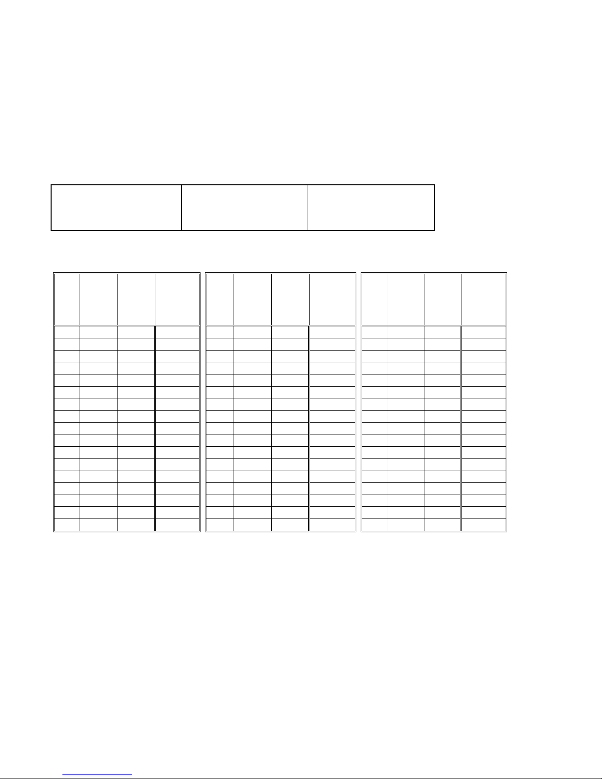
Appendix 5.1
ORP Reference Solution Offset Correction Addition Factors
Temp%
(0C)%
ORP%
Standard%
Solution%
*(mV)%
Eh%(SHE)%
(mV)%
Correction%
Addition%
Factor%
Temp%
(0C)%
ORP%
Standard%
Solution%
(mV)%
Eh%(SHE)%
(mV)%
Correction%
Addition%
Factor%
Temp%
(0C)%
ORP%
Standard%
Solution%
(mV)%
Eh%(SHE)%
(mV)%
Correction%
Addition%
Factor%
0%
218%
438%
220%
17%
219%
426%
207%
34%
220%
412%
192%1%218%
437%
219%
18%
219%
425%
206%
35%
220%
411%
191%2%218%
437%
219%
19%
219%
424%
205%
36%
220%
410%
190%3%218%
436%
218%
20%
219%
424%
205%
37%
220%
409%
189%4%218%
435%
217%
21%
219%
423%
204%
38%
220%
408%
188%5%218%
435%
217%
22%
219%
422%
203%
39%
220%
407%
187%6%218%
434%
216%
23%
219%
421%
202%
40%
220%
406%
186%7%218%
433%
215%
24%
220%
420%
200%
41%
220%
405%
185%8%218%
433%
215%
25#
220#
420#
200#
42%
220%
404%
184%9%219%
432%
213%
26%
220%
419%
199%
43%
220%
403%
183%
10%
219%
431%
212%
27%
220%
418%
198%
44%
220%
402%
182%
11%
219%
430%
211%
28%
220%
417%
197%
45%
220%
401%
181%
12%
219%
430%
211%
29%
220%
416%
196%
46%
220%
400%
180%
13%
219%
429%
210%
30%
220%
415%
195%
47%
220%
399%
179%
14%
219%
428%
209%
31%
220%
414%
194%
48%
220%
398%
178%
15%
219%
428%
209%
32%
220%
413%
193%
49%
220%
397%
177%
16%
219%
427%
208%
33%
220%
412%
192%
50%
220%
396%
176%
Note:%*%Using%pH/mV%electrode%with%4M%KCL%Ag/Ag%CL%reference%solution%
Page 12
VWR sympHony
Meter User Guide
Exhibit 5.2
Page 13

I
sympHony™ Meter User Guide
Table of Contents
Chapter I Introduction
Convenient Meter Features ............................................ 1
Chapter II Display
General Description .................................................. 3
Chapter III Keypad
General Description .................................................. 5
Key Definitions . . . . . . . . . . . . . . . . . . . . . . . . . . . . . . . . . . . . . . . . . . . . . . . . . . . . . . 6
Chapter IV Preparation
Installing the Power Adapter............................................ 7
Installing the Batteries ................................................ 8
Connecting the Electrodes ............................................. 9
Turning on the Instrument .............................................10
Meter Maintenance ..................................................10
Chapter V Meter Setup
Setup Menu ........................................................11
Setup Menu Table ..................................................12
Enabling or Disabling the Setup Menu Password..........................13
General Menu Settings................................................14
Time and Date Setup .................................................15
AUTO-READ™, Continuous or Timed Measurement Selection ..................16
Selecting the Measurement Parameter ...................................17
Method Setup...................................................... 18
Chapter VI pH Technique
pH Setup Menu .....................................................19
pH Calibration ...................................................... 20
pH Measurement ................................................... 21
mV, Relative mV and ORP Technique .................................... 22
Page 14

II
sympHony™ Meter User Guide
Chapter VII Dissolved Oxygen Technique
Dissolved Oxygen Setup Menu ........................................ 23
Dissolved Oxygen Calibration.......................................... 24
Dissolved Oxygen Measurement ....................................... 26
Chapter VIII Conductivity Technique
Conductivity Setup Menu ............................................. 27
Conductivity Calibration .............................................. 28
Conductivity Measurement ........................................... 30
Chapter IX ISE Technique
ISE Setup Menu .................................................... 31
ISE Standards Preparations ........................................... 32
ISE Calibration ..................................................... 33
ISE Measurement................................................... 34
Chapter X Data Archiving and Retrieval
Datalog and Calibration Log ........................................... 35
Chapter XI Declaration of Conformity
Declaration of Conformity............................................. 37
WEEE Compliance .................................................. 38
Chapter XII Troubleshooting
Meter Self Test ..................................................... 39
Meter Error Codes .................................................. 40
General Troubleshooting .............................................. 42
Chapter XIII Meter Specifications
Meter Specifications................................................. 45
Ordering Information ................................................ 48
Appendix A Special Meter Setup Menu Features
pH Setup Menu Features ............................................. 51
Dissolved Oxygen Setup Menu Features ................................. 51
Conductivity Setup Menu Features ..................................... 52
ISE Setup Menu Features............................................. 54
Tabl e of C on te nts
Page 15

1
sympHony™ Meter User Guide
Chapter I
Introduction
Congratulations! You have selected a VWR® sympHony™ meter designed for
electrochemistry measurements in the field or in the laboratory.
• Single parameter meters provide single measurement of pH, dissolved oxygen,
or conductivity.
• Dual parameter meters provide dual measurements of pH/dissolved oxygen,
pH/conductivity, or pH/ISE (ion selective electrode).
• Multiple parameter meters provide multiple measurements of pH, ISE, dissolved
oxygen, and conductivity.
All meters include a temperature measurement function. All meters with pH
measurement capability include a mV/relative mV/ORP function.
Convenient Meter Features
Built to meet the demands of busy, multiple user laboratories or plant environments,
all meters are microprocessor controlled aiding in the delivery of accurate and
precise measurements. To better meet the needs of users in environmental
protection and control, food and beverage, pharmaceutical, and consumer product
laboratories, the sympHony meters include these key features:
• Password Protected Methods – The meter will save up to ten custom
measurements and calibrations for future reference. Password protection of the
setup menu eliminates any tampering with methods as multiple users access
only the procedure most appropriate to their work.
• AUTO-READ™ – The meter will take a measurement and automatically print or
log the data when the reading becomes stable. The measurement is frozen on
the display until the user prompts the meter to take a new measurement.
Page 16

2
sympHony™ Meter User Guide
• Stirrer Control – Benchtop meters have a control for the stirrer probe and the
AUTO-STIR™ BOD probe, eliminating the need for additional stir plates and bars.
• Display Backlight – When the meter is on, a quick press of will turn
the backlight on and off. When the meter is operating on battery power, the
backlight will automatically turn off after two minutes to conserve power. When
batteries are low, the backlight will no longer turn on.
• Automatic Shut-off – All sympHony meters will shut down after 20 minutes
without a keypress. This maximizes battery power on portable meters and
benchtop meters that are being run on battery power.
• Audible Signals – The meter will beep whenever a key is pressed, providing
immediate verification that the user’s input was received.
• Visual Alarm Signals – Flashing and icons indicate that calibration
settings need adjustment. For more detail, refer to subsequent sections of this
user guide that discuss specific measurement techniques.
An easy-to-use reference guide, attached to each meter, supports daily meter use.
Note: Please read this user guide thoroughly before using your benchtop or
portable meter. Any use outside of these instructions may invalidate your warranty
and cause permanent damage to the meter.
Introduction
Page 17
3
sympHony™ Meter User Guide
Chapter II
Display
General Description
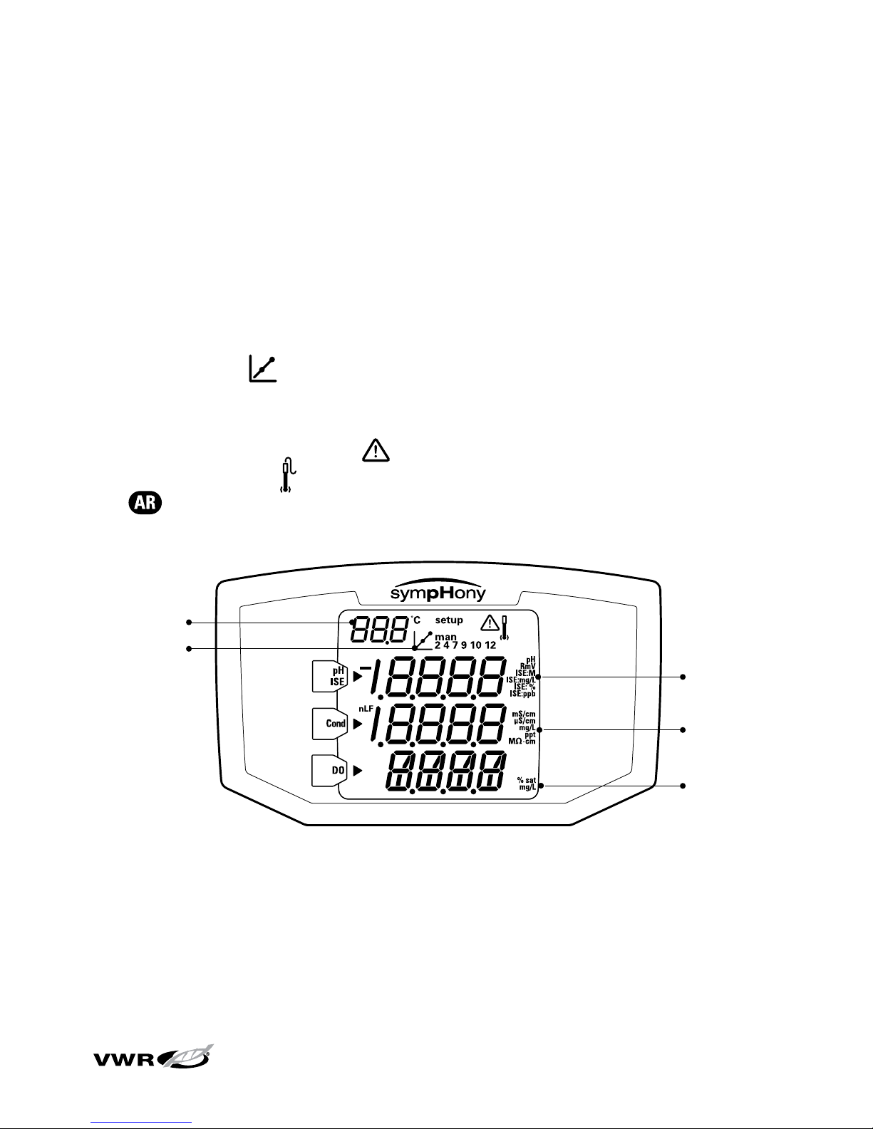
Throughout a given process, the display on a sympHony meter provides
temperature and calibration data. The temperature appears in the left, top corner
of the display. The icon indicates that a calibration mode or calibration setup
menu is active. The man, 2, 4, 7, 9, 10, and 12 icons indicate which pH buffers
were saved after a pH calibration is performed. The setup icon only appears when
the meter is in setup mode. The icon indicates an error condition and when
it is displayed with the icon, a calibration alarm or sensor quality issue exists.
The icon indicates that the AUTO-READ measurement mode is active and is
discussed in greater detail in the Meter Setup section.
Multi-Parameter Meter
This is the display of the sympHony meter capable of multi-parameter
measurements. The single and dual parameter meters will have fewer
measurement lines, depending on the meter capabilities.
Note: In the measurement mode, the three main lines of data on the meter
display correspond to what is being measured.
Temperature
Calibration
pH/ISE/ORP
Unit
Conductivity
Unit
DO Unit
Page 18
4
sympHony™ Meter User Guide
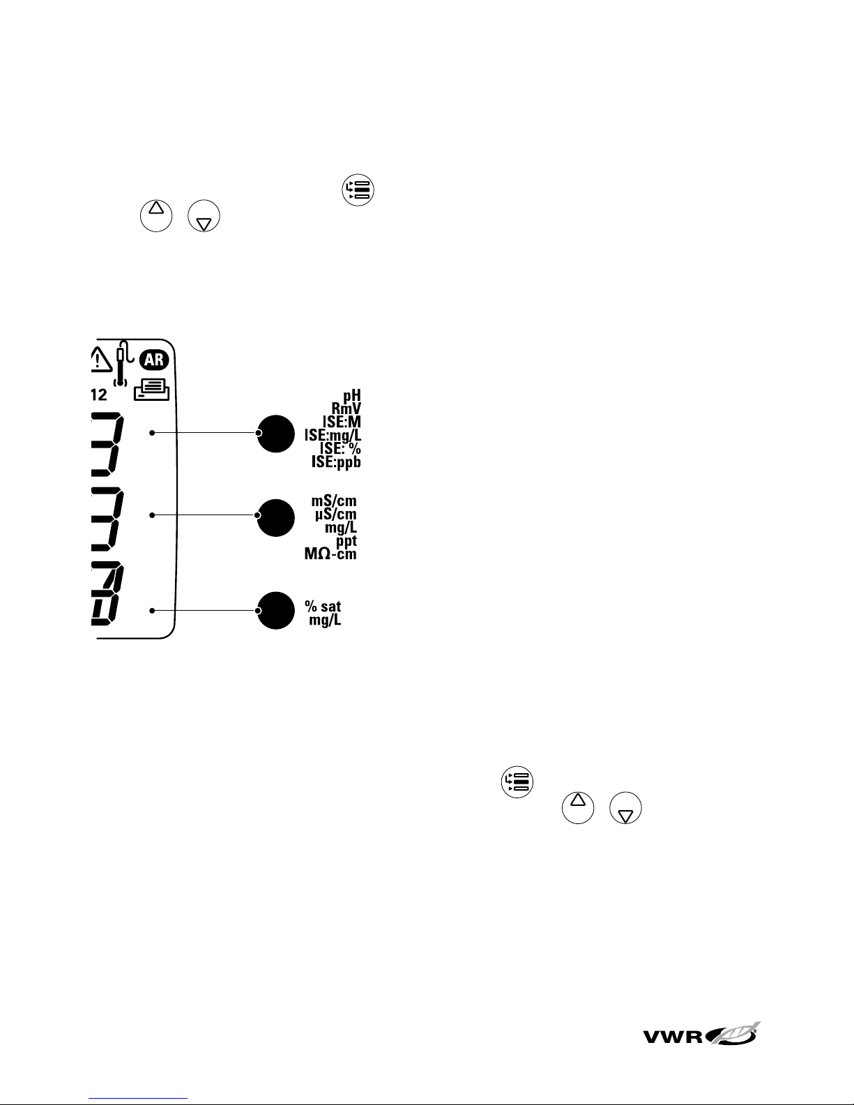
Measurement Unit Icons
In the measurement mode, the arrow icon on the left side of the display screen
indicates the active line. Press to move the arrow icon to the desired line and
press / to scroll through the measurement unit icons associated with
the selected line. The measurement unit icons for the sympHony multi-parameter
meter are shown below. The single and dual parameter meters will have fewer
measurement lines and icons, depending on the meter capabilities.
A
pH, mV, relative mV or ISE
B
Conductivity, TDS, salinity or
resistivity
C
Dissolved oxygen as % saturation,
dissolved oxygen as concentration,
or barometric pressure
The units of measurement, which are displayed on the right side of the screen, will
flash until the reading is stable.
Note: If a measurement line is not needed, press to move the arrow
icon to the measurement line that is not needed and press / until the
measurement line is completely blank.
Display
Page 19
5
sympHony™ Meter User Guide
Chapter III
Keypad
General Description
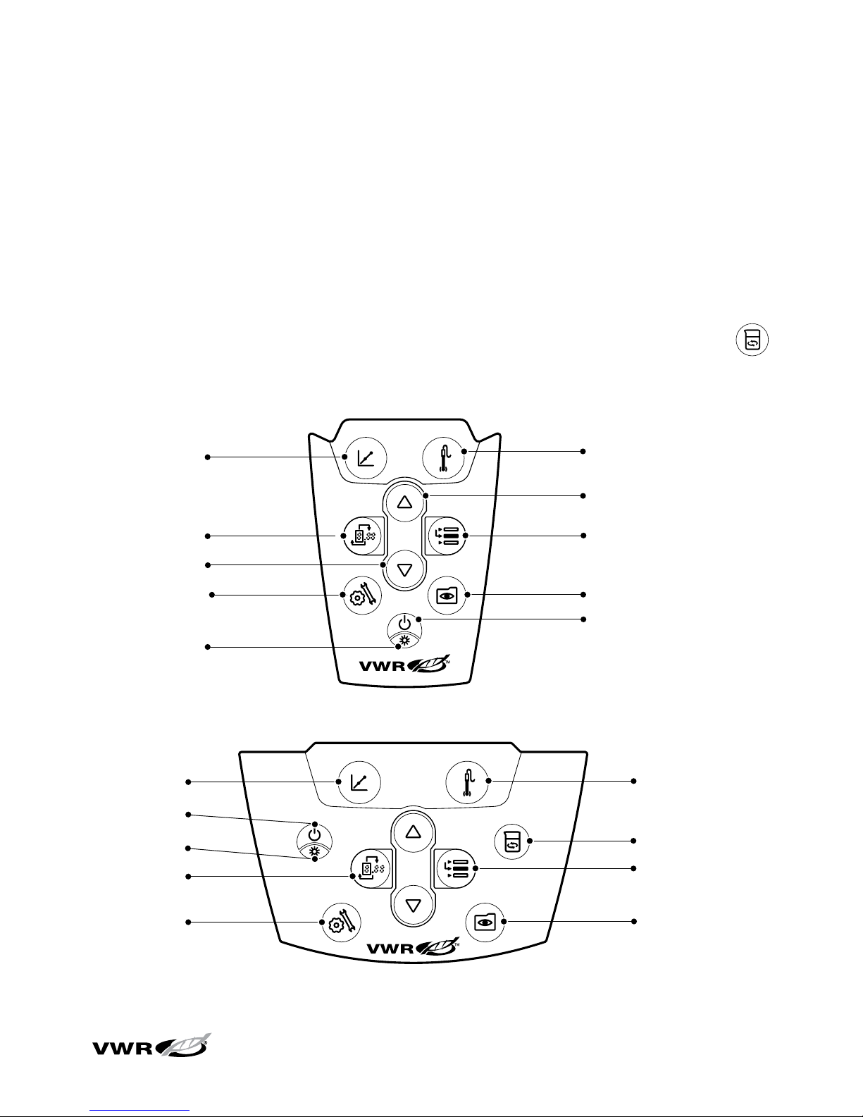
The keypad layout is the same for all sympHony meters. The portable meters have
nine keys. The benchtop meters have ten keys due to the addition of the stir key .
Portable Keypad
Benchtop Keypad
setup view log
calibrate
measure
save/print
Backlight
Power
Measure
Save/Print
View Log
Line Select
Digits
Setup
Calibrate
Scroll Up
Scroll Down
setup view log
calibrate
measure
save/print
Stirrer On/Off
Measure
Save/Print
View Log
Power
Line Select
Digits
Setup
Calibrate
Backlight
Page 20
6
sympHony™ Meter User Guide
Key Definitions
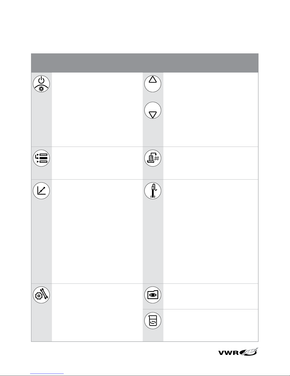
Key Description Key Description
Turns the meter on, if the meter
is off.
Toggles the backlight on and off,
if the meter is on.
If the meter is on, hold down
the key for about three seconds
to turn off the meter.
Changes the measurement
units of the selected line in the
measurement mode.
Changes the value on the
selected line in the setup,
methods and log view modes.
Edits the value of the flashing
digit for setup, password entry
and calibration modes.
Scrolls the arrow icon on left of
screen among the three display
lines, so the selected line can
be edited or calibrated.
Selects the next digit to edit
and moves the decimal point
for setup, password entry and
calibration modes.
Starts the calibration for
the selected line in the
measurement mode.
If the arrow icon points to the
top line and the displayed units
are pH, pressing the key will
start a pH calibration.
Each time the key is pressed in
the calibration mode, the meter
will accept the calibration point
and move to the next point
until the maximum number of
calibration points are reached.
Prints and logs a measurement
in the continuous or timed
measurement modes.
Prints, logs and freezes the
display when the reading
becomes stable in the AUTOREAD measurement mode.
Exits the setup menu and returns
to measurement mode.
Accepts the calibration and
returns to measurement mode.
Enters the setup menu, starting
with selected line in the
measurement mode.
If the arrow icon points to the
top line and the displayed units
are ISE, pressing the key will
enter the ISE setup screen.
Enters the log view and
download menu.
Turns the stirrer on and off.
Keypad
Page 21
7
sympHony™ Meter User Guide
Chapter IV
Preparation
Installing the Power Adapter
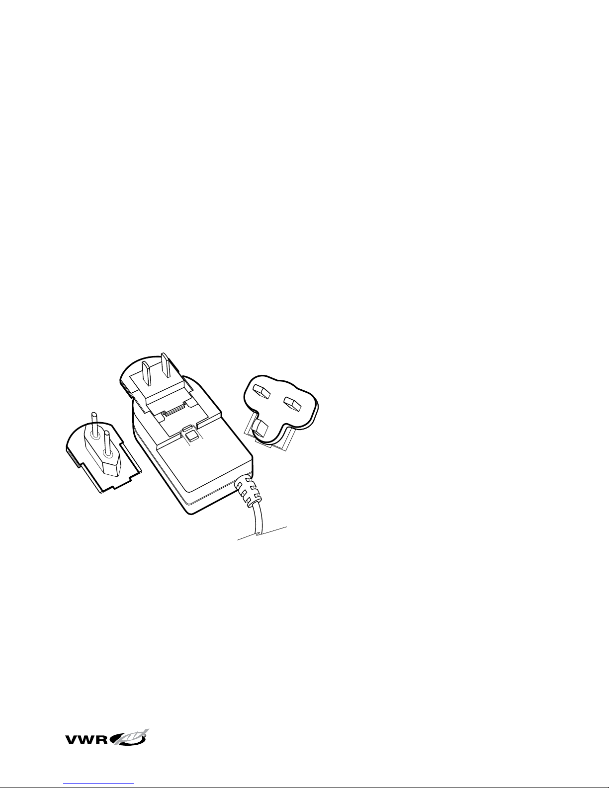
The universal power adapter that is included with your benchtop meter is the only
power adapter recommended for use with this unit. The use of any other power
adapter will void your meter warranty. The external electrical power adapter is rated
to be operated at 100 to 240 VAC, 0.5 A, 50/60 Hz.
Based on your wall outlet, select one of the four plug plates provided (110 V, 220 V,
240V) and slide it into the grooves on the adapter. A click will be heard when the
plug is properly in place.
Connect the output plug of the power adapter to the power input on the benchtop
meter. Refer to the diagram in the Connecting the Electrodes section.
Batteries can be installed in the benchtop sympHony meters, so the meter setup
settings are protected if the meter is disconnected from the wall outlet or a brief
power outage occurs.
Page 22
8
sympHony™ Meter User Guide
Installing the Batteries
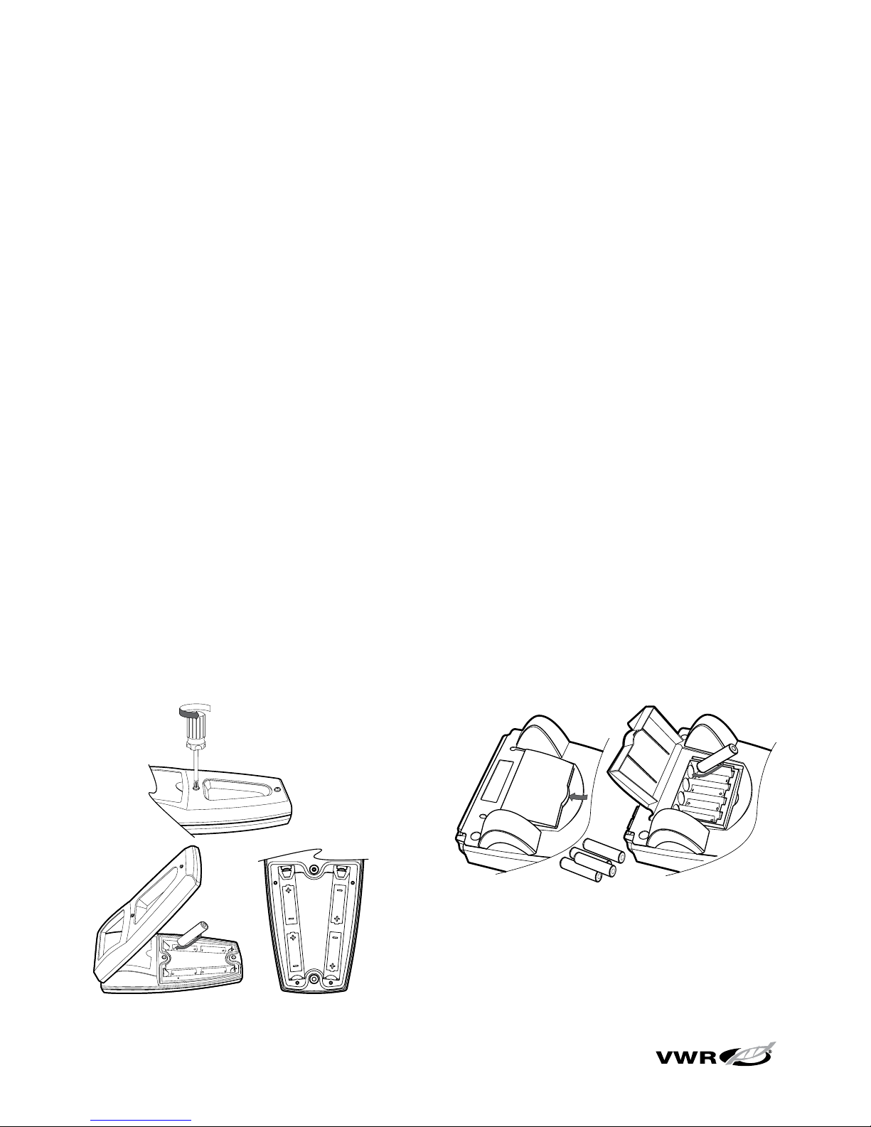
The sympHony meters use four AA alkaline batteries. Do not use lithium or
rechargeable batteries. Improper installation of non-alkaline batteries could create
a hazard.
Note: For benchtop meters, the installation of batteries is not required if the unit
will always be connected to a power source via the universal power supply. For
portable meters, the batteries are supplied from the factory. To access the battery
compartment in portable meters, loosen the two screws in the back of the meter.
1. Confirm that the meter is off and gently place the meter upside down on a
clean, lint-free cloth to prevent scratching the display.
2. Remove the battery case cover.
3. Insert new batteries with the + side orientation as depicted in the battery
compartment housing.
4. Replace the battery case cover.
5. Stored data, calibrations and methods will remain in the meter’s nonvolatile
memory when the batteries are being replaced. However, the date and time
may need to be reset when the batteries are changed.
Preparation
Page 23
9
sympHony™ Meter User Guide
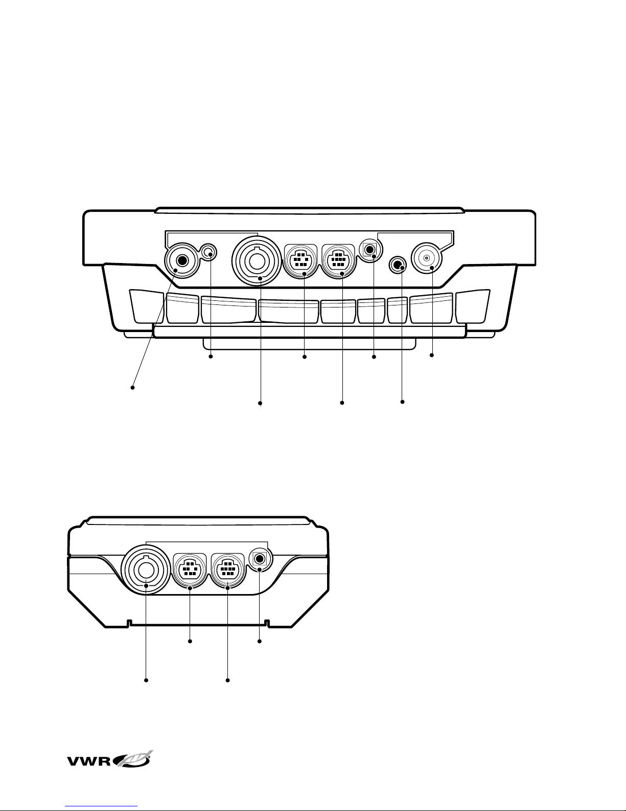
Connecting the Electrodes
Follow the diagrams below to correctly connect electrodes and probes to the meter.
The multi-parameter meter is depicted; single parameter and dual parameter meters
will have fewer connections, depending on the meter measurement capabilities.
Benchtop Meter – Electrode Connections
Stirrer jack,
stirrer or DO
AUTO-STIR probe
Reference,
pH or ISE
Cond or
ATC, 8 pin
MiniDIN
DO, 9 pin
MiniDIN
Ground
BNC,
pH or ISE
Power
RS232
Portable Meter – Electrode Connections
RS232
BNC,
pH or ISE
Cond or
ATC, 8 pin
MiniDIN
DO, 9 pin
MiniDIN
Preparation
Page 24

10
sympHony™ Meter User Guide
Preparation
Meter Connections with Multiple Functions
• Use the BNC input to connect pH, ISE and ORP electrodes with a BNC or
waterproof BNC connector.
• Benchtop meters have a reference input for connecting a separate reference
electrode. Reference electrodes require an appropriate sensing electrode for
measurements.
• Use the waterproof 8 pin MiniDIN input for conductivity probes or for automatic
temperature compensation (ATC) probes.
• The DO AUTO-STIR probe uses the waterproof 9 pin MiniDIN input and the
stirrer jack.
Turning on the Instrument
With the batteries installed in the portable meters and the power adapter attached
or the batteries installed in the benchtop meter, press to turn on the meter.
Press when the meter is powered on to toggle the backlight on and off.
When the benchtop meter is drawing line power, the backlight will stay on until
is pressed.
To t ur n off t he m et er, pr es s an d ho ld for about three seconds.
Meter Maintenance
For routine meter maintenance, dust and wipe the meter with a damp cloth. If
necessary, a warm water or a mild water-based detergent can be used.
Immediately remove any spilled substance from the meter using the proper cleaning
procedure for the type of spill.
Page 25
11
sympHony™ Meter User Guide
Chapter V
Meter Setup
Setup Menu
To navigate the setup menu:
1. Press to enter the setup menu.
2. Press / until the desired setup option is displayed on the top line.
3. Press to move the arrow icon to the middle line.
4. Press / until the desired setup option is displayed on the middle line.
5. Press to move the arrow icon to the bottom line.
6. To s cr ol l th ro ug h a li st o f op ti on s on t he b ott om l in e, p re ss / until the
desired option is displayed. To enter a numeric value for an option on the bottom
line, press / to adjust each digit and to move to the next digit.
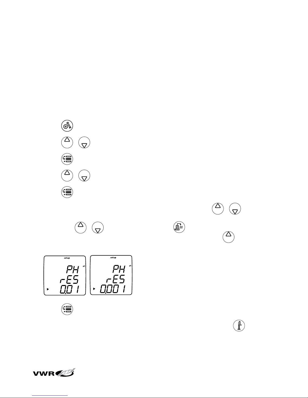
For example, to change the pH measurement resolution press to scroll from
0.01 t o 0.001 on the bottom display line.
7. Press to move the arrow icon to the top line.
8. Repeat steps 2 through 7 to program a new setup option or press to exit
the setup menu and return to the measurement mode.
Page 26

12
sympHony™ Meter User Guide
Setup Menu Table
The following table is for the complete line of sympHony meters. Some sympHony
meters may not include all of the options listed in this table. Refer to Appendix A
for additional information on the special setup menu features.
Top Line Middle Line Bottom Line Setup Menu Description (default setting, method specific)
PH rES 0.1, 0.01, 0.001 pH measurement resolution (0.01, yes)
PH bUF USA, EUr0 pH buffer set for automatic buffer recognition during calibration,
USA buffers are 1.68, 4.01, 7.00, 10.01, 12.46 and EUrO buffers are
1.68, 4.01, 6.86, 9.18 (USA, yes)
ISE rES 1, 2, 3 ISE measurement resolution in significant figures (1, yes)
ISE UnIt m, mgL, PEr, PPb, n0nE ISE measurement units (PPb, yes)
ISE rAng L0w, HIgH ISE concentration range for calibration stability criteria (HIgH, yes)
ISE nLIn AUt0, 0FF ISE automatic blank correction for low-level calibration (AUt0, yes)
C0nd tC 0FF, LIn, nLF Conductivity temperature compensation type, LIn is for linear, nLF is
for non-linear pure water samples (LIn, yes)
C0nd C0EF 0.0 to 10.0 Conductivity temperature compensation coefficient in % change in
conductivity per °C, appears if LIn was selected for tC (2.1, yes)
C0nd tdSF 0.00 to 10.0 Conductivity TDS factor value (0.49, yes)
C0nd CELL 0.001 to 199.0 Conductivity default cell constant value for automatic conductivity
calibration mode (0.475, yes)
C0nd trEF 15, 20, 25 Conductivity reference temperature (25, yes)
C0nd tyPE Std, 1, 2, 3, 4, 5, 6, 7 Conductivity cell type and selectable range (Std, yes)
d0 rES 0.1, 1 % sat DO % saturation measurement resolution (0.1, yes)
d0 rES 0.01, 0.1 mg/L DO mg/L measurement resolution (0.01, yes)
d0 bAr AUt0, mAn DO barometric pressure compensation type (AUt0, yes)
d0 PrES 450.0 to 850.0 DO manual barometric pressure compensation value, appears if
mAn was selected for bAr (760.0, yes)
d0 SAL AUt0, mAn DO salinity correction type (AUt0, yes)
d0 SALF 0 to 45 DO manual salinity correction value, appears if mAn was selected
for SAL or a DO meter without a conductivity mode is used (0, yes)
d0 CALt AIr, H20, mAn, SEt0 DO calibration type (AIr, yes)
dUE PH 0 to 9999 pH calibration alarm value in hours, 0 is off (0, yes)
dUE 0rP 0 to 9999 ORP calibration alarm value in hours, 0 is off (0, yes)
dUE ISE 0 to 9999 ISE calibration alarm value in hours, 0 is off (0, yes)
dUE C0nd 0 to 9999 Conductivity calibration alarm value in hours, 0 is off (0, yes)
dUE d0 0 to 9999 DO calibration alarm value in hours, 0 is off (0, yes)
Meter Setup
Page 27
13
sympHony™ Meter User Guide
Top Line Middle Line Bottom Line Setup Menu Description
(default setting, method specific)
rEAd tyPE AUt0, tImE, C0nt, Measurement read type as AUTO-READ, timed or continuous
(AUt0, yes)
rEAd tInE 00:05 to 99:59 Timed measurement value in minutes and seconds (01:00, yes)
L0g dEL n0, YES Delete datalog after download option (n0, yes)
gEn dEgC -5.0 to 105 Manual temperature value (25.0, yes)
gEn StIr 0FF, 1, 2, 3, 4, 5, 6, 7 Stirrer speed – benchtop meters only (4, yes)
gEn AUt0 0n, 0FF Automatic meter shutoff option (0n, no)
gLP SEt 0FF, 0n GLP option, GLP feature enables or disables methods (0FF, no)
gLP PASS 0000 to 9999 Password entry (0000, no)
dAtE H0Ur HH00 to HH23 Hour setting (HH12, no)
dAtE tInE mm00 to mm59 Minute setting (mm00, no)
dAtE tYPE mdY, dmY Displayed date format as month, day, year or day, month, year
(mdY, no)
dAtE YEAr 2000 to 2099 Year setting (2004, no)
dAtE dAtE mm01 to mm12 Month setting (mm01, no)
dAtE dAY dd01 to dd31 Day of the month setting (dd01, no)
r232 bAUd 1200, 2400, 4800, 9600 Baud rate setting (9600, no)
r232 0UtF Prnt, C0mP Output format for printer or computer, C0mP format is comma
delimited (Prnt, no)
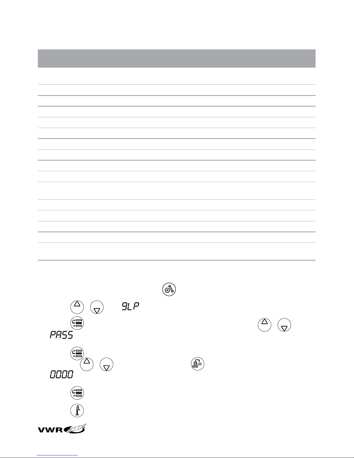
Enabling or Disabling the Setup Menu Password
1. In the measurement mode, press .
2. Press
/ until is displayed on top line.
3. Press
to move the arrow icon to the middle line and press / until
is displayed.
4. Press
to move the arrow icon to the bottom line and enter a password by
pressing / to enter each digit and to move to the next digit. Enter
to disable the password and allow unlimited access to the setup menu.
5. Press
to move the arrow icon to the top line.
6. Press
to exit the setup menu and return to the measurement mode.
Meter Setup
Page 28
14
sympHony™ Meter User Guide
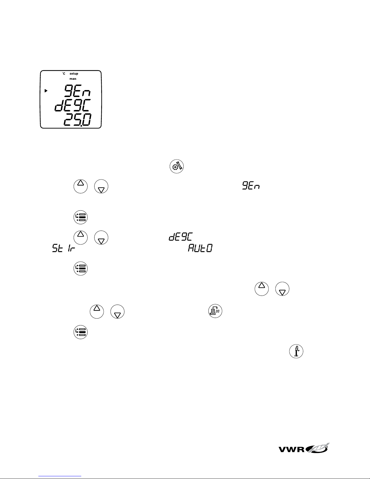
General Menu Settings
• Manual Temperature controls temperature compensation
when no temperature sensor is attached to the meter.
• Stirrer Speed sets the stirrer speed from 1 (slowest)
through 7 (fastest) and off – benchtop meters only.
• Automatic Shutoff controls whether the instrument will
automatically turn off after 20 minutes without a keypress.
1. In the measurement mode, press .
2. Press / to scroll through the setup menu until is displayed on the
top line.
3. Press to accept the selection and move the arrow icon to the middle line.
4. Press / to scroll through for the manual temperature setting,
for the stirrer speed setting and for the automatic shutoff setting.
5. Press to accept the selection and move the arrow icon to the bottom line.
6. To s cr ol l th ro ug h a li st o f op ti on s on t he b ott om l in e, p re ss / until the
desired option is displayed. To enter a numeric value for an option on the bottom
line, press / to adjust each digit and to move to the next digit.
7. Press to accept the selection and move the arrow icon to the top line.
8. Repeat steps 3 through 7 to change another general setting or press to
return to the measurement mode.
Meter Setup
Page 29
15
sympHony™ Meter User Guide
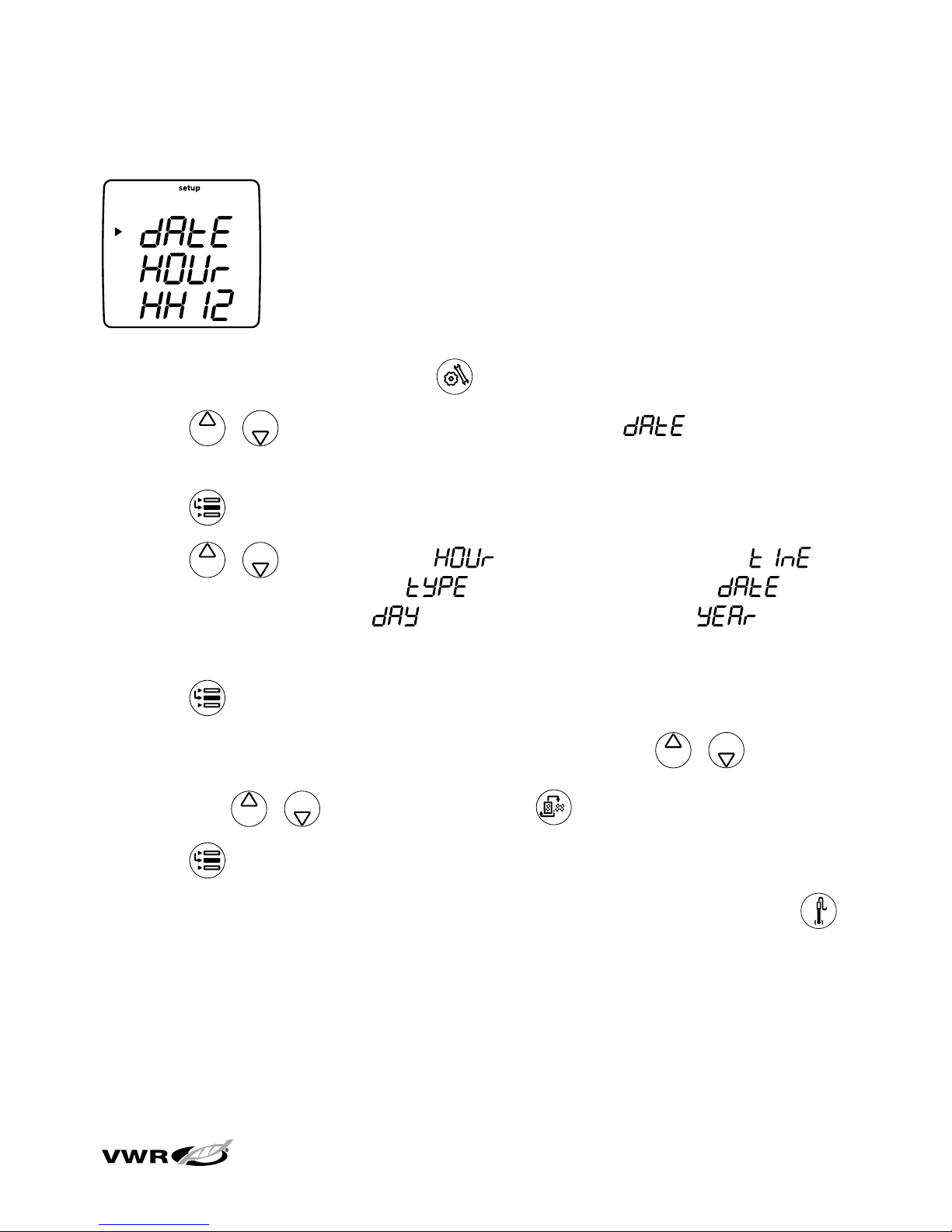
Time and Date Settings
• The date and time settings are saved with the datalog
points and are included with the data that is sent to a
computer or printer.
• The date format can be set to read month, day, year or
day, month, year according to the user’s preference.
1. In the measurement mode, press .
2. Press / to scroll through the setup menu until is displayed on
the top line.
3. Press to accept the selection and move the arrow icon to the middle line.
4. Press / to scroll through for the current hour setting,
for the current minute setting, for the date format setting, for
the current month setting, for the current day setting and for the
current year setting.
5. Press to accept the selection and move the arrow icon to the bottom line.
6. To s cr ol l th ro ug h a li st o f op ti on s on t he b ott om l in e, p re ss / until the
desired option is displayed. To enter a numeric value for an option on the bottom
line, press / to adjust each digit and to move to the next digit.
7. Press to accept the selection and move the arrow icon to the top line.
8. Repeat steps 3 through 7 to change another time and date setting or press
to return to the measurement mode.
Meter Setup
Page 30
16
sympHony™ Meter User Guide
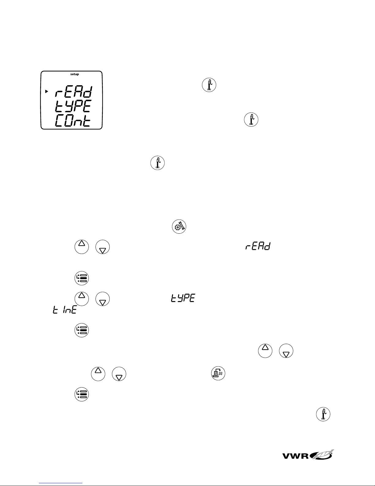
AUTO-READ™, Continuous or Timed Measurement Settings
• In the AUTO-READ mode, the meter starts taking
a measurement when is pressed. Once the
measurement is stable, the display freezes and the data is
logged and printed. The AUTO-READ mode also controls
the stirrer. The stirrer starts when is pressed and stops
when the measurement becomes stable.
• In the continuous mode, the meter is constantly taking measurements and
updating the display. Press to log and print a measurement in this mode.
• In the timed mode, the meter is constantly taking measurements and updating
the display. The meter logs and prints the measurement at the selected
time interval.
1. In the measurement mode, press .
2. Press / to scroll through the setup menu until is displayed on
the top line.
3. Press to accept the selection and move the arrow icon to the middle line.
4. Press / to scroll through for the measurement read type and
for the timed reading interval.
5. Press to accept the selection and move the arrow icon to the bottom line.
6. To s cr ol l th ro ug h a li st o f op ti on s on t he b ott om l in e, p re ss / until the
desired option is displayed. To enter a numeric value for an option on the bottom
line, press / to adjust each digit and to move to the next digit.
7. Press to accept the selection and move the arrow icon to the top line.
8. Repeat steps 3 through 7 to change another measurement setting or press
to return to the measurement mode.
Meter Setup
Page 31
17
sympHony™ Meter User Guide
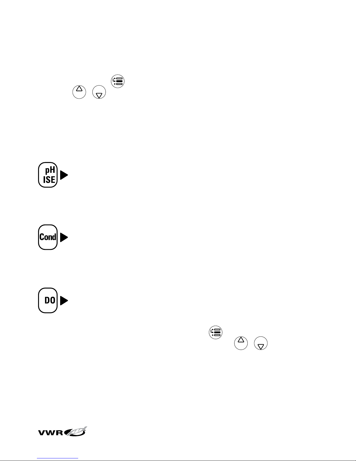
Selecting the Measurement Parameter
In the measurement mode, the arrow icon on the left side of the display indicates
the active line. Press to move the arrow icon to the desired measurement line
and press / to scroll through the measurement parameters associated with
the selected line.
The measurement lines and icons for the sympHony multi-parameter meter are
shown below. The single and dual parameter meters will have fewer measurement
lines and icons, depending on the meter capabilities.
pH
mV
RmV
ISE
No icon and no measurement – the measurement line is turned off
μS/cm or mS/cm for conductivity
mg/L for TDS
ppt for salinity
MΩ-cm for resistivity
No icon and no measurement – the measurement line is turned off
% sat for dissolved oxygen percent saturation
mg/L for dissolved oxygen concentration
No icon for barometric pressure
No icon and no measurement – the measurement line is turned off
Note: If a measurement line is not needed, press to move the arrow
icon to the measurement line that is not needed and press / until the
measurement line is completely blank.
Meter Setup
Page 32
18
sympHony™ Meter User Guide
Method Setup
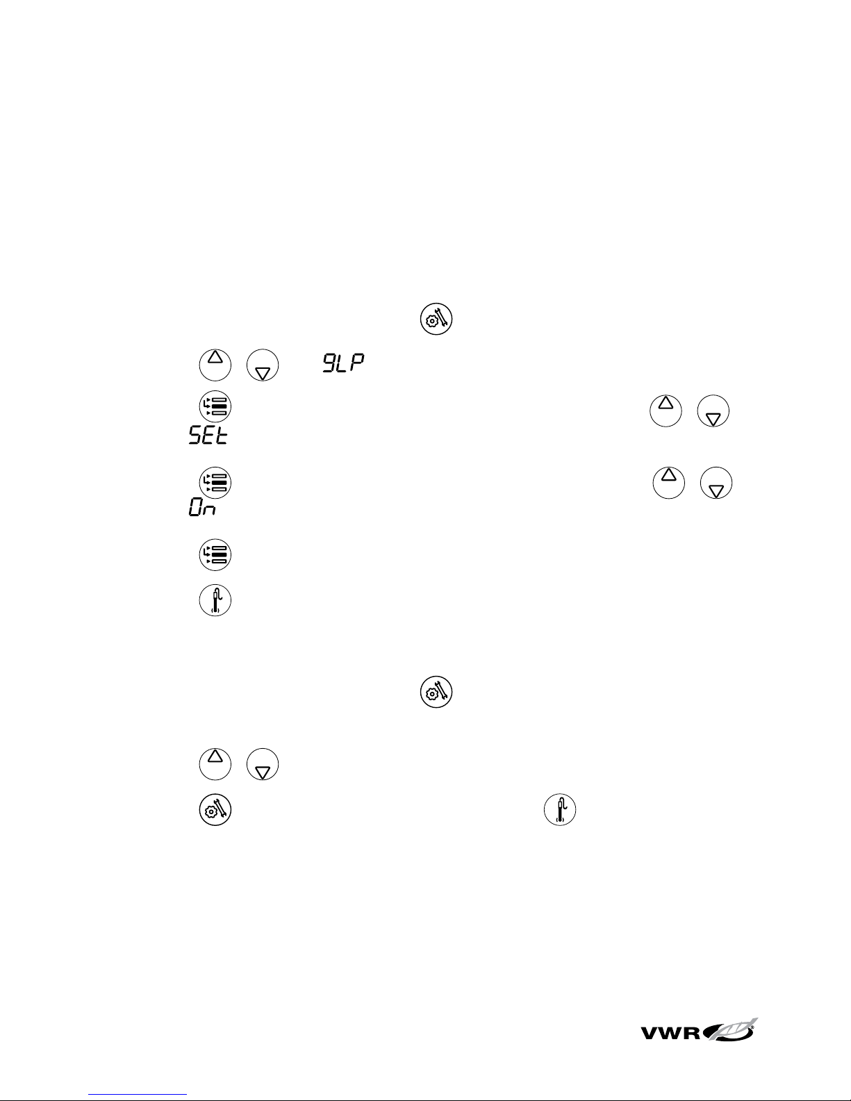
The sympHony meters can save up to 10 methods when the GLP function is
enabled. When a method is selected, the meter will use the last calibration
performed in that method, so electrodes that share a common meter connection
can be more easily interchanged.
1. To enable the GLP function:
a. In the measurement mode, press .
b. Press / until is displayed on top line.
c. Press to move the arrow icon to the middle line and press /
until is displayed.
d. Press to move the arrow icon to the bottom line and press /
until is displayed.
e. Press to move the arrow icon to the top line.
f. Press to exit the setup menu and return to the measurement mode.
2. To display and change the current method number:
a. In the measurement mode, press . The current method number will
be displayed.
b. Press / to select a new method number.
c. Press to save the method number and press to return to the
measurement mode.
Meter Setup
Page 33
19
sympHony™ Meter User Guide
Chapter VI
pH Technique
pH Setup Menu
Note: Refer to the Meter Setup section for the Setup Menu Table, which contains
a complete list of meter setup options and descriptions.
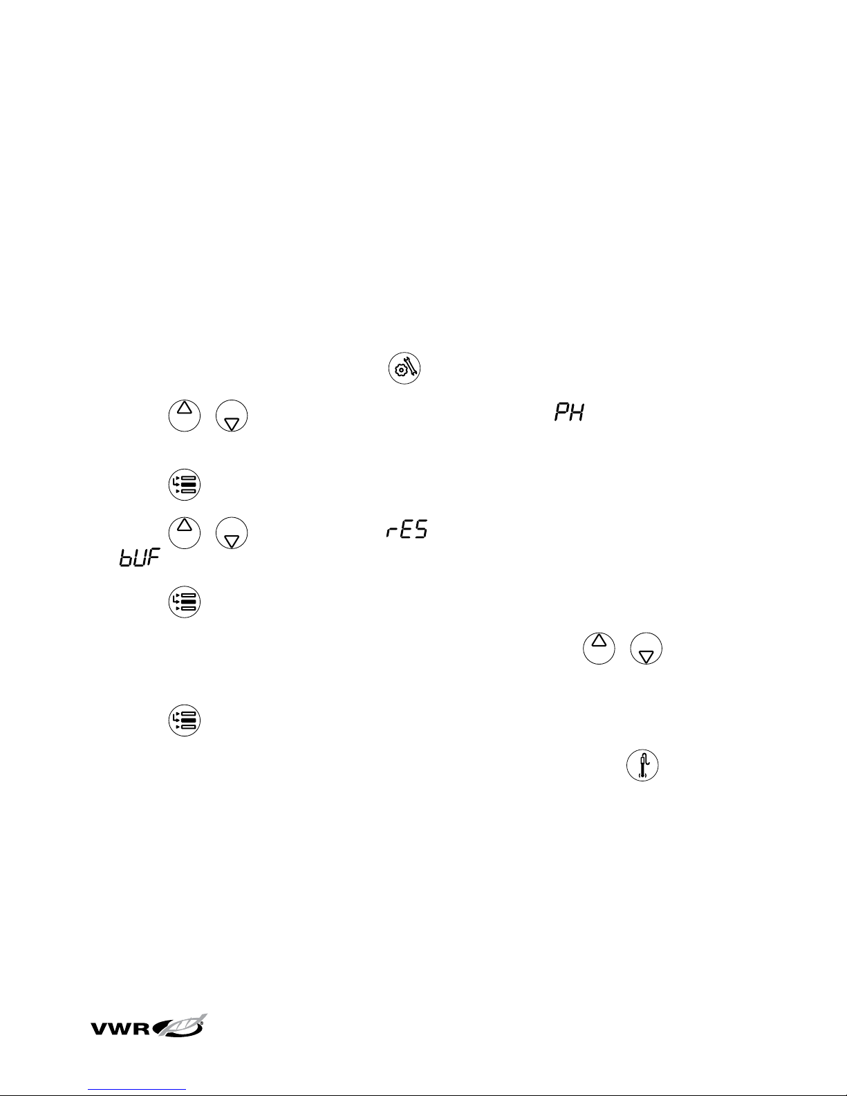
1. In the measurement mode, press .
2. Press / to scroll through the setup menu until is displayed on the
top line.
3. Press to accept the selection and move the arrow icon to the middle line.
4. Press / to scroll through for pH measurement resolution and
for the automatic buffer recognition setting.
5. Press to accept the selection and move the arrow icon to the bottom line.
6. To s cr ol l th ro ug h a li st o f op ti on s on t he b ott om l in e, p re ss / until the
desired option is displayed.
7. Press to accept the selection and move the arrow icon to the top line.
8. Repeat steps 3 through 7 to change another pH setting or press to return to
the measurement mode.
Page 34
20
sympHony™ Meter User Guide
pH Calibration
1. Prepare the electrode according to the electrode user guide.
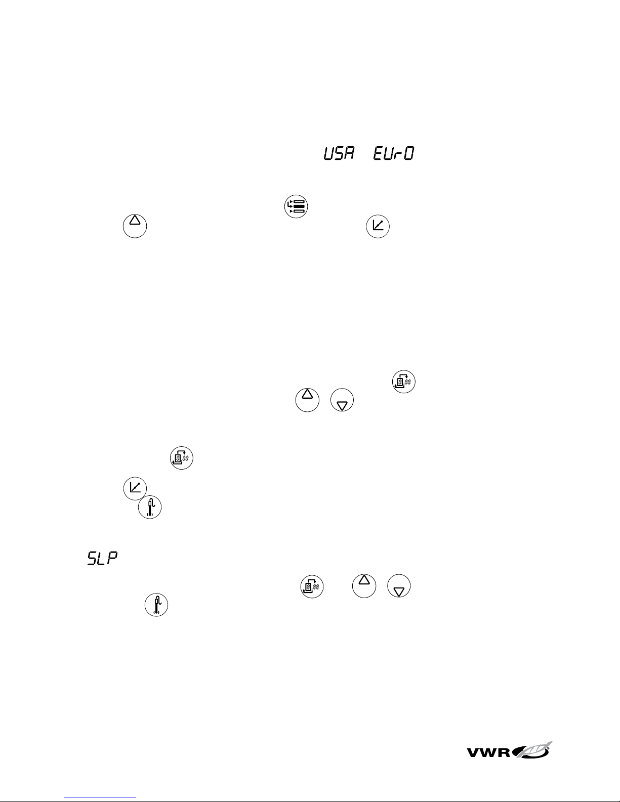
2. In the setup mode, select the buffer set ( or ) that will be used for
the automatic buffer recognition feature.
3. In the measurement mode, press until the arrow icon points to the top line,
press until the pH icon is shown and press to begin the calibration.
4. Rinse the electrode and ATC probe with distilled water and place into the buffer.
5. Wait for the pH icon to stop flashing.
a. Automatic buffer recognition – When the
pH icon stops flashing the meter
will display the temperature-corrected pH value for the buffer.
b. Manual calibration – When the pH icon stops flashing the meter will display
the actual pH value read by the electrode. Press
until the first digit
to be changed is flashing, press / to change the value of the
flashing digit and continue to change the digits until the meter displays the
temperature-corrected pH value of the buffer. Once the pH buffer value is
set, press until the decimal point is in the correct location.
6. Press
to proceed to the next calibration point and repeat steps 4 and 5
or press to save and end the calibration.
7. The actual electrode slope, in percent, will be displayed in the main field and
will be displayed in the lower field.
a. For a one point calibration, press
and / to edit the slope and
press to return to the measurement mode.
b. For a two or more point calibration, the meter will automatically proceed to
the measurement mode after the slope is displayed.
pH Technique
Page 35
21
sympHony™ Meter User Guide
pH Measurement
1. Rinse the electrode with distilled or deionized water. Shake off any excess
water and blot the electrode dry with lint-free tissue.
2. Place the electrode into the sample.
a. If the meter is in the continuous measurement mode, it will start reading
immediately and continuously update the display. The
pH icon will flash
until the reading is stable. For mV, relative mV or ORP measurements, the
mV or RmV icon will flash until the reading is stable. Once the reading is
stable, log and print the measurement by pressing
. If a benchtop meter
is used and the stirrer is enabled, press to start the stirrer. Press
again to turn off the stirrer before removing the electrode and stirrer from
the sample.
b. If the meter is in the AUTO-READ measurement mode, press to start
the reading. The AR icon will flash until the reading is stable. Once the
reading is stable, the meter will log and print the measurement and freeze
the display. If a benchtop meter is used and the stirrer is enabled, the stirrer
will turn on when is pressed and turn off when the reading is stable.
c. If the meter is in the timed measurement mode, it will start reading
immediately and continuously update the display. The meter will log and
print the measurement at the frequency specified in the setup menu. If a
benchtop meter is used and the stirrer is enabled, press to start the
stirrer. Press again to turn off the stirrer before removing the electrode
and stirrer from the sample.
3. Remove the electrode from the sample, rinse it with distilled or deionized water,
blot it dry, place it in the next sample and repeat step 2.
4. Once all of the samples have been measured, rinse the electrode with distilled
or deionized water and blot it dry. Consult the electrode user guide for proper
storage techniques.
pH Technique
Page 36
22
sympHony™ Meter User Guide
mV, Relative mV and ORP Technique
All meters with pH measurement capability include a mV, relative mV and ORP
function. Measure the raw millivolt (mV) values of an electrode in the mV mode.
Calibrate the relative millivolt (RmV) values of a redox electrode for oxidationreduction potential (ORP) measurements in the relative mV and ORP mode.
Note: The mV measurements are raw readings and cannot be calibrated. Use the
relative mV mode to calibrate mV measurements.
Relative mV and ORP Calibration
1. Prepare the electrode according to the electrode user guide.
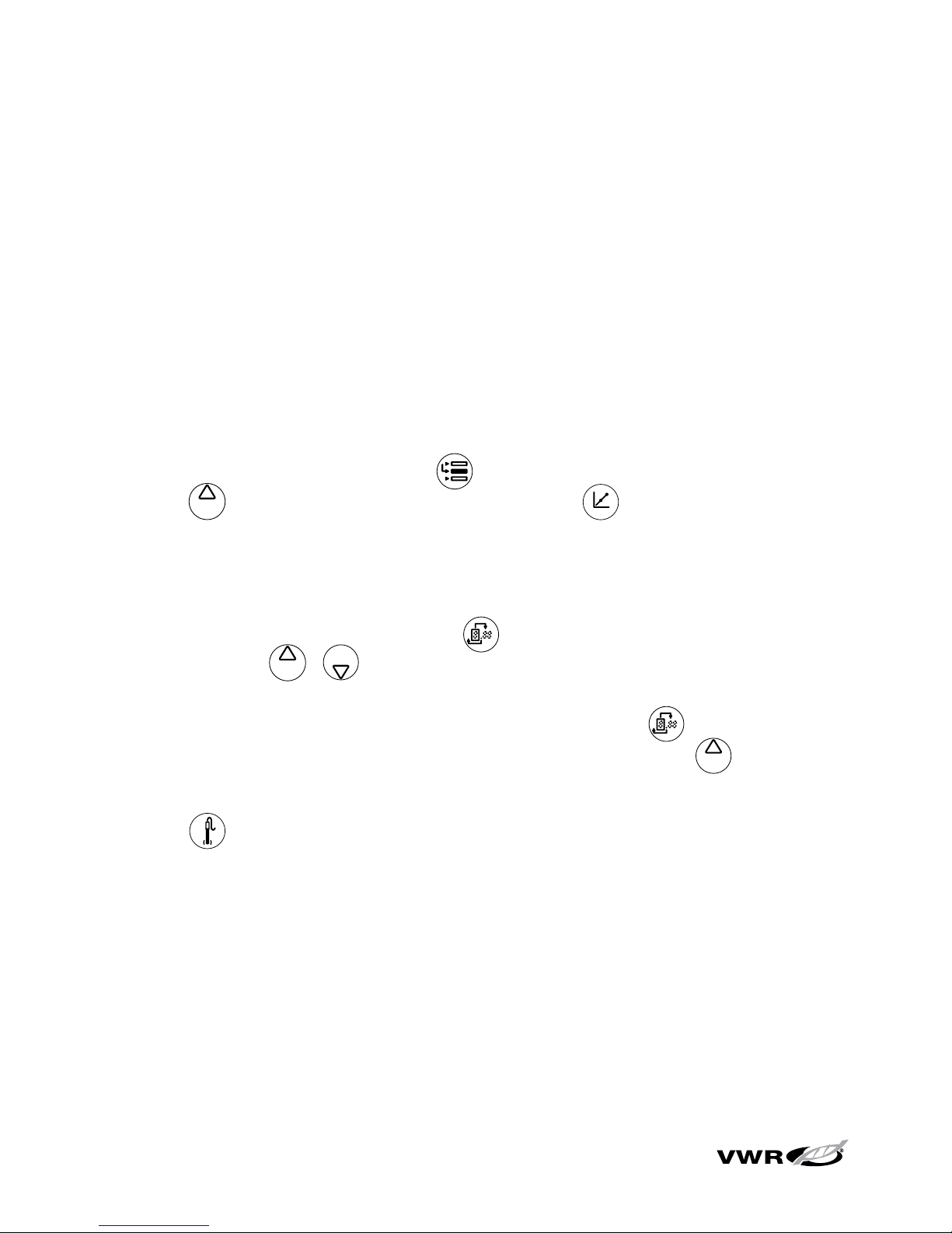
2. In the measurement mode, press until the arrow icon points to the top line,
press until the RmV icon is shown and press to begin the calibration.
3. Rinse the electrode with distilled water and place it into the standard.
4. Wait for the RmV icon to stop flashing. When the RmV icon stops flashing, the
meter will display 000.0 RmV. Press until the first digit to be changed is
flashing, press / to change the value of the flashing digit and continue
to change the digits until the meter displays the millivolt value of the standard.
To ch an ge t he va lu e to n eg at ive o r po si ti ve n um be r, p re ss until none of the
digits are blinking and the arrow icon is blinking and then press to change
the sign of the millivolt value.
5. Press to save and end the calibration.
6. The millivolt offset will be displayed and the meter will automatically proceed to
the measurement mode.
7. Refer to the pH Measurement section for instructions on mV, relative mV and
ORP measurements.
pH Technique
Page 37
23
sympHony™ Meter User Guide
Chapter VII
Dissolved Oxygen Technique
Dissolved Oxygen Setup Menu
Note: Refer to the Meter Setup section for the Setup Menu Table, which contains
a complete list of meter setup options and descriptions.
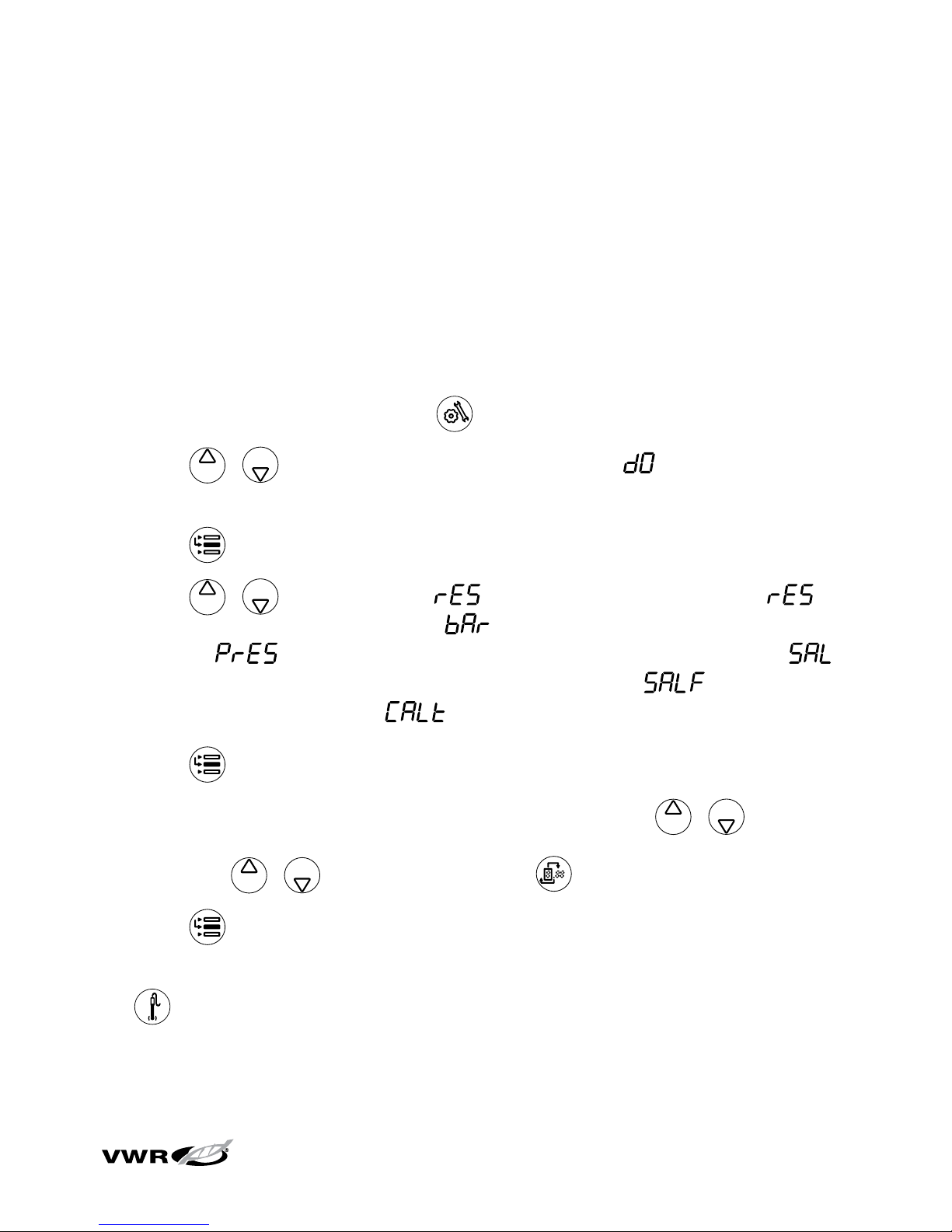
1. In the measurement mode, press .
2. Press / to scroll through the setup menu until is displayed on the
top line.
3. Press to accept the selection and move the arrow icon to the middle line.
4. Press / to scroll through for the % saturation resolution, for
the mg/L concentration resolution, for the barometer type (automatic or
manual), for the manual barometric pressure compensation value,
for the salinity compensation type (automatic or manual), for the manual
salinity correction value and for the dissolved oxygen calibration type.
5. Press to select the option and move the arrow icon to the bottom line.
6. To s cr ol l th ro ug h a li st o f op ti on s on t he b ott om l in e, p re ss / until the
desired option is displayed. To enter a numeric value for an option on the bottom
line, press / to adjust each digit and to move to the next digit.
7. Press to accept the selection and move the arrow icon to the top line.
8. Repeat steps 3 through 7 to change another dissolved oxygen setting or press
to return to the measurement mode.
Page 38

24
sympHony™ Meter User Guide
Dissolved Oxygen Calibration
• Prior to calibration, the dissolved oxygen probe must be prepared and polarized.
The probe is continuously polarized when it is connected to the meter. When
the probe is first connected or if the probe is disconnected for more than 60
minutes, connect the probe to the meter, connect the meter to a power source
and wait 30 to 60 minutes for the probe to polarize. Disconnecting the probe for
less than one hour will require 5 to 25 minutes for polarization.
• The meters will supply a polarization current to the dissolved oxygen probe even
when the meter power is off. To maximize the meter battery life, unplug the
probe if it will not be used for an extended period.
1. Select one of the following calibration modes in the setup menu.
a.
– An air calibration is performed in water saturated air using the
calibration sleeve. This is the simplest and most accurate calibration. Due to
the inherent differences between water saturated air and air saturated water,
102.3% saturation will be displayed when the calibration reading is stable.
i. The highest possible accuracy is reached when calibration temperature is
the same as the measuring temperature.
ii. Moisten the sponge or absorbent cloth in the calibration sleeve with
distilled water and insert the probe into the sleeve without touching the
water saturated material. For BOD measurements, this calibration can be
performed in a BOD bottle.
b.
– A water calibration is performed using water that is 100% saturated
with air. Bubble air into a water sample and gently stir the sample to prevent
the buildup of air bubbles on the dissolved oxygen probe membrane.
c. – A manual calibration is performed using a water sample with a
known concentration of dissolved oxygen. This method can be used to
calibrate the dissolved oxygen probe to the value achieved by a
Winkler titration.
Dissolved Oxygen Technique
Page 39
25
sympHony™ Meter User Guide
i. A manual calibration involves performing a Winkler titration and using
that sample as a calibration standard. The oxygen level result from the
titration is entered in a manual calibration as the dissolved oxygen value.
This correlates the meter input to the Winkler titration. This method is
inherently less accurate, due to the possibility of titration errors.
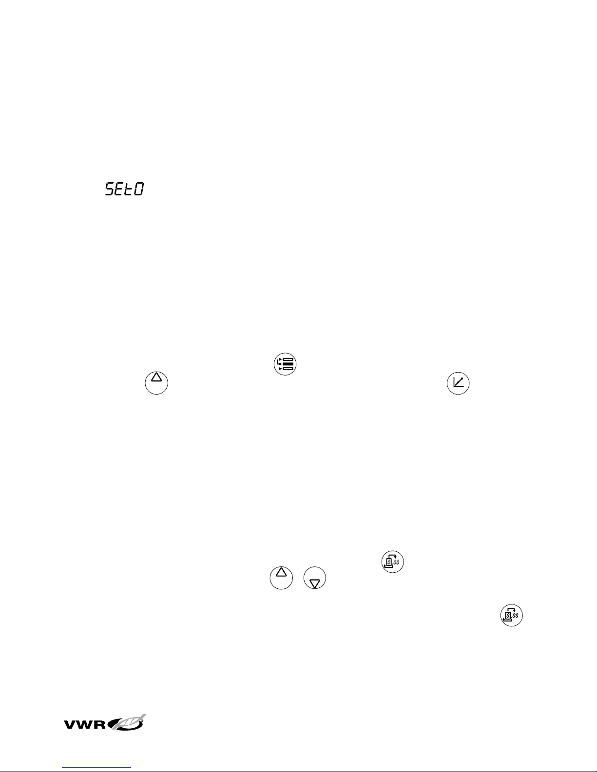
d.
– A zero point calibration is performed in an oxygen-free solution. A
zero point calibration is not generally required unless measurements will
be taken below 5% saturation or 0.5 mg/L. Zero the probe when using a
new membrane, using fresh filling solution or when measuring dissolved
oxygen levels below 1 mg/L or 10% saturation. An air calibration should be
performed prior to the zero point calibration.
2. Allow the probe and calibration standard (water saturated air, air saturated water,
Winkler standard or oxygen-free solution) to reach equilibrium.
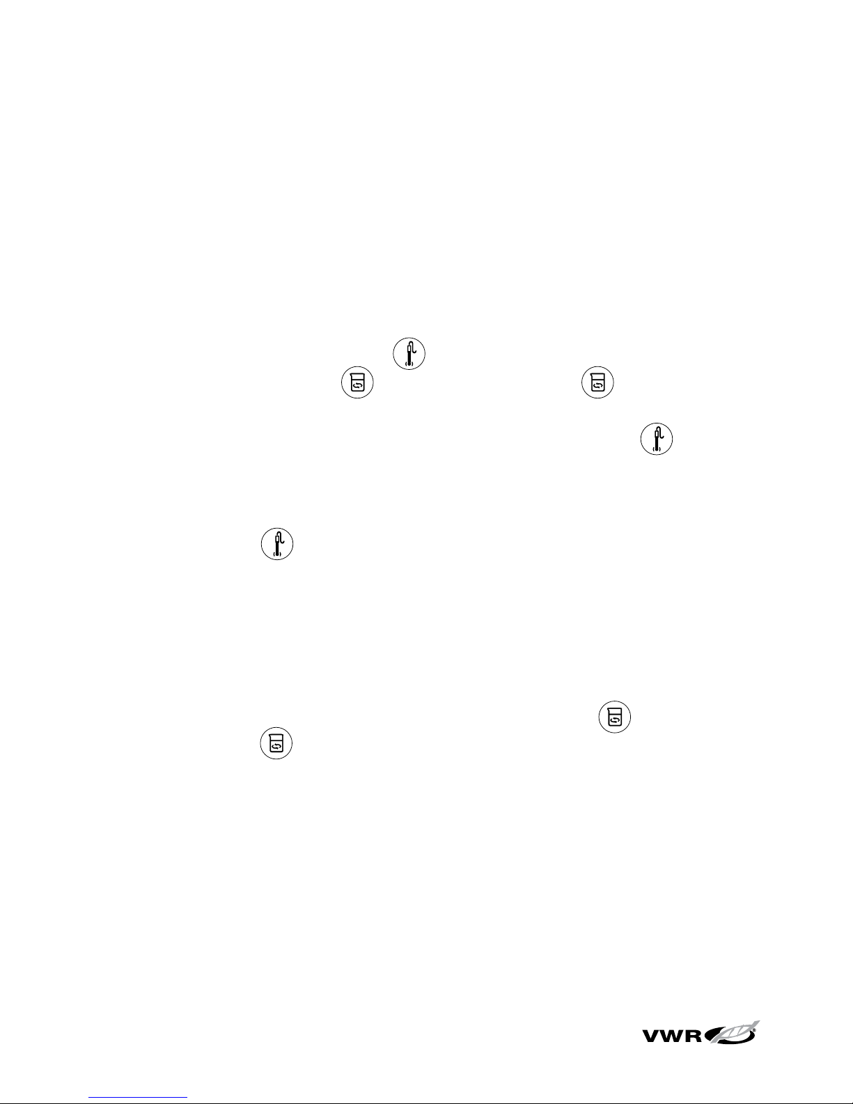
3. In the measurement mode, press until the arrow icon points to the bottom
line, press until the % sat or mg/L icon is shown and press to begin
the calibration.
4. Wait for the dissolved oxygen reading to stabilize.
a. If an air calibration is performed, the meter will display 102.3% and
automatically return to the measurement mode.
b. If a water calibration is performed, the meter will display 100.0% and
automatically return to the measurement mode.
c. If a manual calibration is performed, wait for the
mg/L icon to stop flashing
and enter the dissolved oxygen value by pressing
until the first digit to
be changed is flashing, press / to change the value of the flashing
digit and continue to change the digits until the meter displays the correct
dissolved oxygen value. Once the dissolved oxygen value is set, press
until the decimal point is in the correct location.
d. If a zero point calibration is performed, the meter will display 0.00 and
automatically return to the measurement mode.
Dissolved Oxygen Technique
Page 40
26
sympHony™ Meter User Guide
Dissolved Oxygen Measurement
1. Rinse the dissolved oxygen probe with distilled or deionized water. Shake off
any excess water and blot the probe dry with lint-free tissue.
2. Place the dissolved oxygen probe into the sample.
a. If the meter is in the continuous measurement mode, it will start reading
immediately and continuously update the display. The
mg/L or % sat icon
will flash until the reading is stable. Once the reading is stable, log and print
the measurement by pressing
. If a benchtop meter is used and the
stirrer is enabled, press to start the stirrer. Press again to turn off
the stirrer before removing the probe and stirrer from the sample.
b. If the meter is in the AUTO-READ measurement mode, press to start
the reading. The AR icon will flash until the reading is stable. Once the
reading is stable, the meter will log and print the reading and freeze the
display. If a benchtop meter is used and the stirrer is enabled, the stirrer will
turn on when is pressed and turn off when the reading is stable.
If the BOD AUTO-STIR probe is used, press the button on the probe to start
the AUTO-READ measurement.
c. If the meter is in the timed measurement mode, it will start reading
immediately and continuously update the display. The meter will log and
print the measurement at the frequency specified in the setup menu. If a
benchtop meter is used and the stirrer is enabled, press to start the
stirrer. Press again to turn off the stirrer before removing the probe and
stirrer from the sample.
3. Remove the dissolved oxygen probe from the sample, rinse it with distilled or
deionized water, blot it dry, place it in the next sample and repeat step 2.
4. Once all of the samples have been measured, rinse the dissolved oxygen probe
with distilled or deionized water and blot it dry. Consult the dissolved oxygen
probe user guide for proper storage techniques.
Dissolved Oxygen Technique
Page 41
27
sympHony™ Meter User Guide
Chapter VIII
Conductivity Technique
Conductivity Setup Menu
Note: Refer to the Meter Setup section for the Setup Menu Table, which contains
a complete list of meter setup options and descriptions.
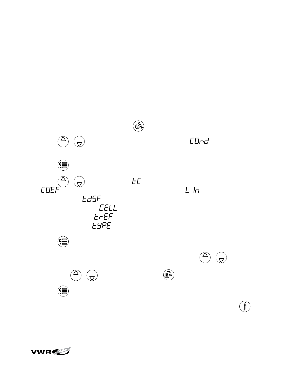
1. In the measurement mode, press .
2. Press / to scroll through the setup menu until is displayed on
the top line.
3. Press to accept the selection and move the arrow icon to the middle line.
4. Press / to scroll through for the temperature compensation type,
for the temperature coefficient value used for temperature
compensation, for the TDS factor value used for total dissolved
solids measurement, for the nominal cell constant value of the
conductivity probe, for the reference temperature used for temperature
compensation and for the conductivity cell type.
5. Press to accept the selection and move the arrow icon to the bottom line.
6. To s cr ol l th ro ug h a li st o f op ti on s on t he b ott om l in e, p re ss / until the
desired option is displayed. To enter a numeric value for an option on the bottom
line, press / to adjust each digit and to move to the next digit.
7. Press to accept the selection and move the arrow icon to the top line.
8. Repeat steps 3 through 7 to change another conductivity setting or press to
return to the measurement mode.
Page 42
28
sympHony™ Meter User Guide
Conductivity Calibration
Note: For an automatic calibration, the nominal cell constant of the conductivity
probe must be entered in the setup menu before the calibration is performed. Refer
to the conductivity probe user guide for the nominal cell constant value.
1. In the measurement mode, press until the arrow icon points to the middle
line, press until the µS/cm or mS/cm icon is shown and press to
begin the calibration.
2. Rinse the conductivity probe with deionized water and place it into the
conductivity standard.
3. To perform a manual calibration – The manual calibration screen will display
the cell constant on the bottom line, the conductivity value of the calibration
standard on the middle line and on the top line. To change the cell
constant, press until the first digit to be changed is flashing, press /
to change the value of the flashing digit and continue to change the digits
until the displayed conductivity value matches the value of the standard at the
measured temperature. Once the value is set, press until the decimal point
is in the correct location. Press to save and end the calibration.
Note: In the manual calibration screen, start changing the cell constant within
five seconds or the meter will proceed to the automatic/direct calibration. If this
occurs, press and hold to abort the calibration and repeat the calibration.
4. To perform an automatic or direct calibration – Wait for the meter to go from
the manual calibration screen to the automatic/direct calibration screen. The
automatic/direct calibration screen will display the conductivity value of the
calibration standard on the middle line and on the bottom line.
a. Automatic calibration – When the µS/cm or mS/cm icon stops flashing, the
meter will display the temperature-corrected conductivity of the standard.
Conductivity Technique
Page 43
29
sympHony™ Meter User Guide
b. Direct calibration – When the µS/cm or mS/cm icon stops flashing, the
meter will display the actual conductivity value read by the probe. To
change the conductivity value, press until the first digit to be changed
is flashing, press / to change the value of the flashing digit and
continue to change the digits until the correct conductivity value of the
standard at the measured temperature is displayed. Once the value is set,
press until the decimal point is in the correct location.
5. Press
to proceed to the next calibration point, rinse the conductivity probe
with distilled or deionized water, place it into the next conductivity standard and
repeat step 4a / 4b or press to save and end the calibration.
6. The cell constant will be displayed in the main field and the meter will
automatically advance to the measurement mode.
Conductivity Technique
Page 44
30
sympHony™ Meter User Guide
Conductivity Measurement
1. Rinse the conductivity probe with distilled or deionized water. Shake off any
excess water and blot the probe dry with lint-free tissue.
2. Place the conductivity probe into the sample.
a. If the meter is in the continuous measurement mode, it will start reading
immediately and continuously update the display. The
μS/cm or mS/cm
icon will flash until the reading is stable. Once the reading is stable, log and
print the measurement by pressing
. If a benchtop meter is used and
the stirrer is enabled, press to start the stirrer. Press again to turn
off the stirrer before removing the probe and stirrer from the sample.
b. If the meter is in the AUTO-READ measurement mode, press to start
the reading. The AR icon will flash until the reading is stable. Once the
reading is stable, the meter will log and print the measurement and freeze
the display. If a benchtop meter is used and the stirrer is enabled, the stirrer
will turn on when is pressed and turn off when the reading is stable.
c. If the meter is in the timed measurement mode, it will start reading
immediately and continuously update the display. The meter will log and
print the measurement at the frequency specified in the setup menu. If a
benchtop meter is used and the stirrer is enabled, press to start the
stirrer. Press again to turn off the stirrer before removing the probe and
stirrer from the sample.
3. Remove the conductivity probe from the sample, rinse it with distilled or
deionized water, blot it dry, place it in the next sample and repeat step 2.
4. Once all of the samples have been measured, rinse the conductivity probe with
distilled or deionized water and blot it dry. Consult the conductivity probe user
guide for proper storage techniques.
Conductivity Technique
Page 45
31
sympHony™ Meter User Guide
Chapter IX
ISE Technique
ISE Setup Menu
Note: Refer to the Meter Setup section for the Setup Menu Table, which contains
a complete list of meter setup options and descriptions.
1. In the measurement mode, press .
2. Press / to scroll through the setup menu until is displayed on the
top line.
3. Press to accept the selection and move the arrow icon to the middle line.
4. Press / to scroll through for the ISE measurement resolution,
for the ISE measurement units, for the ISE calibration range and
for the non-linear blank correction feature.
5. Press to accept the selection and move the arrow icon to the bottom line.
6. To s cr ol l th ro ug h a li st o f op ti on s on t he b ott om l in e, p re ss / until the
desired option is displayed. To enter a numeric value for an option on the bottom
line, press / to adjust each digit and to move to the next digit.
7. Press to accept the selection and move the arrow icon to the top line.
8. Repeat steps 3 through 7 to change another ISE setting or press to return
to the measurement mode.
Page 46

32
sympHony™ Meter User Guide
Preparation of Standards
Serial dilution with volumetric glassware is the best method for making a set
of calibration standards. The calibration points should bracket the expected
concentration range of the samples. There should be a tenfold change in
concentration (i.e. 1 ppm and 10 ppm or 50 ppm and 500 ppm) between the
standards. Fresh standard should be used at each calibration.
Serial Dilutions
Serial dilution is the best method for the preparation of standards. Serial dilution
means that an initial standard is diluted, using volumetric glassware, to prepare a
second standard solution. The second standard is similarly diluted to prepare a third
standard, and so on, until the desired range of standards has been prepared.
1. To p re pa re a 10-2 M standard, pipette 10 mL of the 0.1 M standard into a 100 mL
volumetric flask, dilute to the mark with deionized water and mix well.
2. To pr ep ar e a 10-3 M standard, pipette 10 mL of the 10-2 M standard into a 100
mL volumetric flask, dilute to the mark with deionized water and mix well.
3. To pr ep ar e a 10-4 M standard, pipette 10 mL of the 10-3 M standard into a 100
mL volumetric flask, dilute to the mark with deionized water and mix well.
To p re pa re s ta nd ar ds w it h a di ff er en t co nc en tr at io n us e th e fo ll ow in g fo rm ul a:
C1 V1 = C2 V
2
Where:
C1 = concentration of original standard
V1 = volume of original standard
C2 = concentration of standard after dilution
V2 = volume of standard after dilution
ISE Technique
Page 47
33
sympHony™ Meter User Guide
ISE Calibration
The calibration standards should be prepared in the same ISE units as the desired
sample results. Start the calibration with the lowest concentration calibration
standard and work up to the highest concentration calibration standard. Any
reagents, such as ionic strength adjustors, should be added to samples and
standards as specified in the electrode user guide.
1. Prepare the electrode, standards and any other required solutions for use
according to the electrode user guide.
2. In the measurement mode, press until the arrow icon points to the top line,
press until the ISE icon is shown and press to begin the calibration.
3. Rinse the electrode with distilled or deionized water, shake any excess water off,
blot it dry and place the electrode into the least concentrated standard.
4. Wait for ISE icon to stop flashing. Press until the first digit to be changed
is flashing, press / to change the value of the flashing digit and
continue to change the digits until the meter displays the concentration value of
the standard. Once the standard value is set, press until the decimal point
is in the correct location.
5. Press to proceed to the next lowest calibration standard and repeat
steps 3 and 4, working from the lowest concentration standard to the highest
concentration standard, or press to save and end the calibration.
6. The actual electrode slope, in mV per decade concentration, will be displayed in
the main field and will be displayed in the lower field.
a. For a one point calibration, press
and / to edit the slope. To
change the sign of the slope to negative or positive, press until none of
the digits are blinking and the arrow icon is blinking and press to change
the sign of the slope. Press to return to the measurement mode.
b. For a two or more point calibration, the meter will automatically proceed to
the measurement mode after the slope is displayed.
ISE Technique
Page 48
34
sympHony™ Meter User Guide
ISE Measurement
1. Rinse the electrode with distilled or deionized water. Shake off any excess
water and blot the electrode dry with lint-free tissue.
2. Place the electrode into the sample.
a. If the meter is in the continuous measurement mode, it will start reading
immediately and continuously update the display. The
ISE icon will flash
until the reading is stable. Once the reading is stable, log and print the
measurement by pressing
. If a benchtop meter is used and the stirrer
is enabled, press to start the stirrer. Press again to turn off the
stirrer before removing the electrode and stirrer from the sample.
b. If the meter is in the AUTO-READ measurement mode, press to start
the reading. The AR icon will flash until the reading is stable. Once the
reading is stable, the meter will log and print the measurement and freeze
the display. If a benchtop meter is used and the stirrer is enabled, the stirrer
will turn on when is pressed and turn off when the reading is stable.
c. If the meter is in the timed measurement mode, it will start reading
immediately and continuously update the display. The meter will log and
print the measurement at the frequency specified in the setup menu. If a
benchtop meter is used and the stirrer is enabled, press to start the
stirrer. Press again to turn off the stirrer before removing the electrode
and stirrer from the sample.
3. Remove the electrode from the sample, rinse it with distilled or deionized water,
blot it dry, place it in the next sample and repeat step 2.
4. Once all of the samples have been measured, rinse the electrode with distilled
or deionized water and blot it dry. Consult the electrode user guide for proper
storage techniques.
ISE Technique
Page 49
35
sympHony™ Meter User Guide
Chapter X
Data Archiving and Retrieval
Datalog and Calibration Log
The sympHony meters have a 200 point datalog that includes the last ten
calibrations that were successfully performed on the meter.
Datalog Deletion Setting
The datalog deletion setting determines if the meter will automatically delete
the datalog after it is downloaded to a printer or computer and if the meter will
overwrite the datalog points when the datalog is full. If the datalog deletion setting
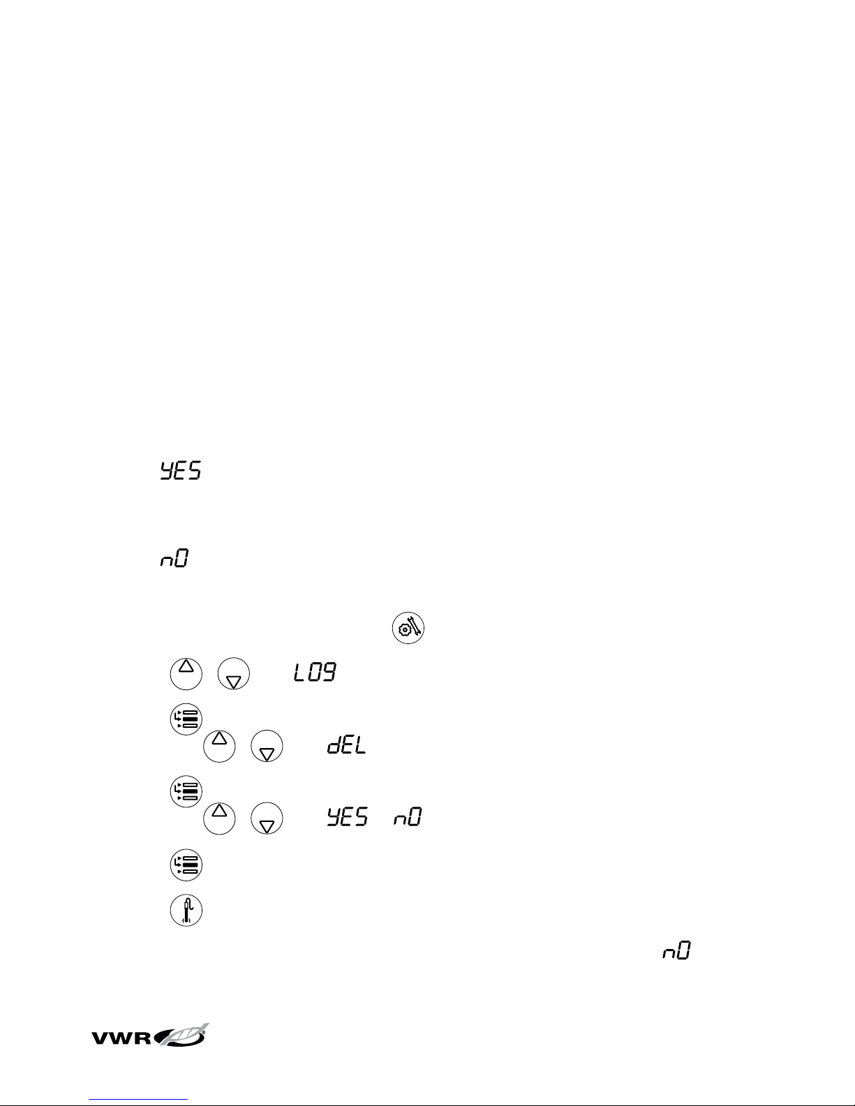
is set to , the meter will automatically delete the datalog after the datalog
is downloaded to a printer or computer. The meter will also display an error 038
message when all 200 datalog points are filled and the datalog must be downloaded
to a printer or computer to clear the error message. If the datalog deletion setting
is set to , the meter will overwrite the oldest datalog point when all 200 datalog
points are filled.
1. In the measurement mode, press .
2. Press / until is displayed on top line.
3. Press to accept the selection and move the arrow icon to the middle line
and press / until is displayed.
4. Press to accept the selection and move the arrow icon to the bottom line
and press / until or is displayed.
5. Press to accept the selection and move the arrow icon to the top line.
6. Press to save the setup option and return to measurement mode.
Note: If the datalog is not required, set the datalog deletion setting to to
prevent the error 038 (datalog full) message.
Page 50
36
sympHony™ Meter User Guide
Viewing and Downloading the Datalog and Calibration Log
The sympHony meters include datalog view, datalog download and calibration log
download features.
To view the datalog:
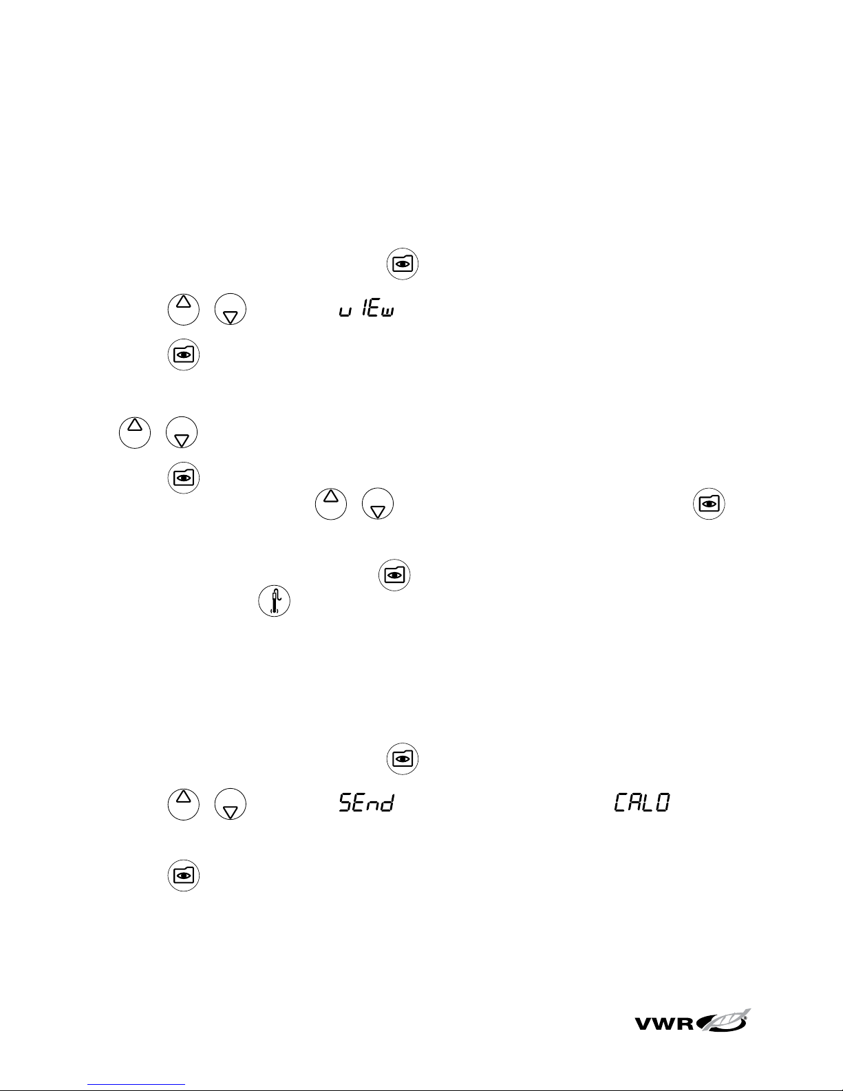
1. In the measurement mode, press .
2. Press / to scroll to to view the datalog.
3. Press . The meter will display the date/time screen. The datalog number
will be on the top of the screen and the time, date and year the datalog was
recorded will be on the top, middle and bottom display lines respectively. Press
/ to scroll through the datalog.
4. Press . The meter will display the data point associated with the selected
date/time screen. Press / to scroll through the datalog or press to
return to the date/time screen.
5. To e xi t th e lo g vi ew mo de , pr es s until the meter displays the date/time
screen and press .
To send the datalog or calibration log to a printer or computer:
1. Connect the meter to a printer or computer and verify the meter baud rate and
output settings in the setup menu.
2. In the measurement mode, press .
3. Press / to scroll to to download the datalog or to
download the calibration log.
4. Press to send the selected data to the printer or computer.
Data Archiving and Retrieval
Page 51

37
sympHony™ Meter User Guide
Chapter XI
Declaration of Conformity
Address: 166 Cummings Center
Beverly, MA 01915
USA
We declare that the following products described below conform to the Directive
and Standard listed below:
Product(s): Meters for measuring pH, conductivity, dissolved oxygen, and/or ISE
Benchtop models are rated 100 to 240 VAC, 50/60 Hz, 0.5 A
Handheld models use four non-rechargeable AA batteries
Benchtop Meters Portable Meters
SB70P benchtop meter SP70P portable meter
SB70D benchtop meter SP70D portable meter
SB70C benchtop meter SP70C portable meter
SB80PI benchtop meter SP80PI portable meter
SB80PD benchtop meter SP80PD portable meter
SB80PC benchtop meter SP80PC portable meter
SB90M5 benchtop meter SP90M5 portable meter
Equipment Class: Measurement, control and laboratory
Benchtop models are EMC Class A
Portable models are EMC Class D
Page 52

38
sympHony™ Meter User Guide
Directive(s) and Standard(s):
• 89/336/EEC – Electromagnetic Compatibility (EMC Directive)
• EN 61326:1997 + A1:1998 + A2:2001 – Electrical equipment for
measurement, control, and laboratory use – EMC requirements
• 73/23/EEC – Low Voltage Directive (LVD)
• EN 61010-1:2001 – Safety requirements for electrical equipment for
measurement, control, and laboratory use – general requirements
Manufacturer’s Authorized Representative: Date:
Patrick Chiu Februar y 22, 2005
Senior Quality Assurance Engineering,
Regulatory Compliance
WEEE Compliance:
This product is required to comply with the European Union’s Waste
Electrical & Electronic Equipment (WEEE) Directive 2002/96/EC.
It is marked with the following symbol:
We have contracted with one or more recycling/disposal companies in each EU
Member State and this product should be disposed of or recycled through them.
Further information on compliance with these Directives, the recyclers in your
country, and information on Thermo Scientific Orion products which may assist the
detection of substances subject to the RoHS Directive are available at
www.thermo.com/WEEERoHS.
Declaration of Conformity
Page 53
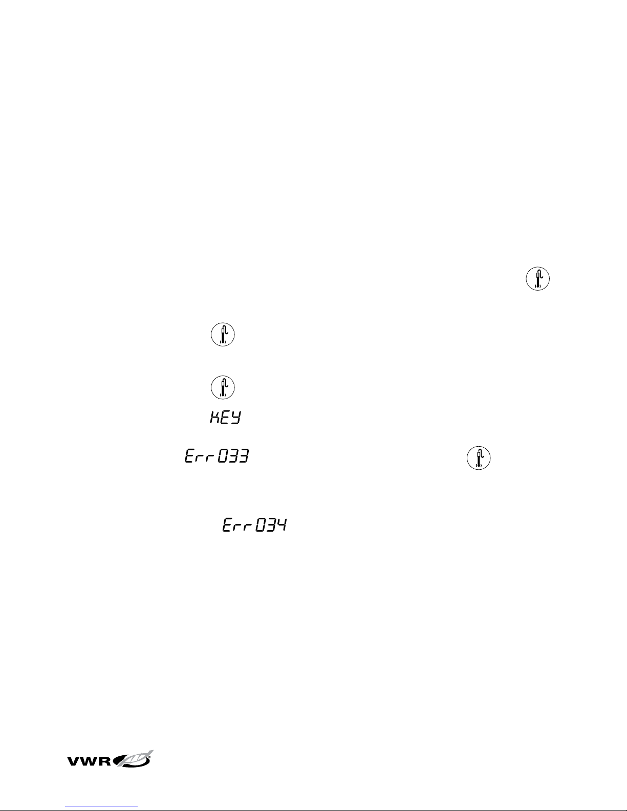
39
sympHony™ Meter User Guide
Chapter XII
Troubleshooting
Meter Self Test
1. Disconnect all of the electrodes and probes from the meter and cover all of the
meter inputs with the black caps.
2. Power on the meter, wait until the software revision is displayed and press .
3. All the segments on the display will light up. Visually inspect the display
segments and press .
4. All the segments on the display will turn off. Visually inspect the display
segments and press .
5. The display will read . Press every key on the keypad one at a time in
any order. If the keys are not pressed within five seconds of one another, the
display will read , which indicates a key failure. Press to clear
the error 033 message and complete the self test. If all the keys are pressed
and functioning, the meter will restart and proceed to the measurement mode.
Note: If the meter reads during the self test, ensure that all of the
electrodes are disconnected from the meter, all of the meter inputs are covered
with the black caps and the BNC shorting cap is firmly attached to the BNC meter
input. This error code usually occurs if the BNC shorting cap is missing or not fully
connected to the BNC meter input during the meter self test.
Page 54
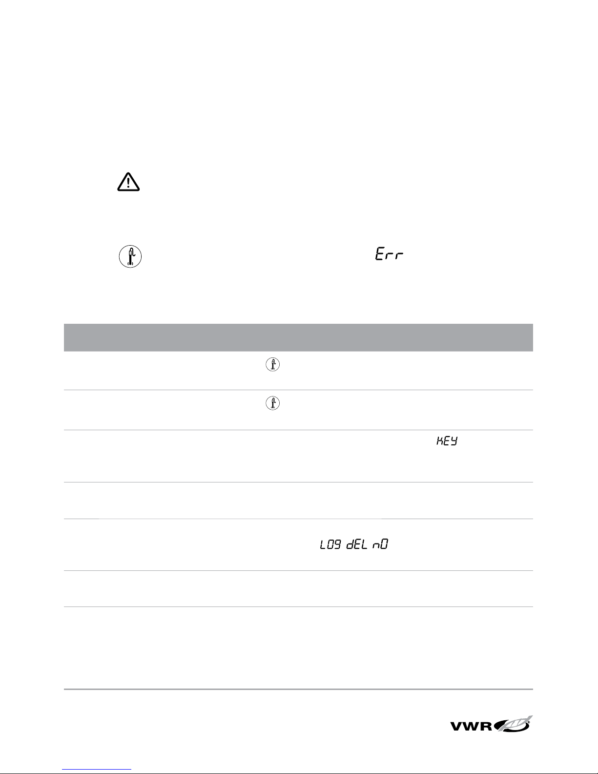
40
sympHony™ Meter User Guide
Meter Error Codes
• If the reading on the screen is flashing 9999, the value is out of range. Perform
the meter self test, clean the electrode according to the electrode user guide
and re-calibrate the electrode with new standards.
• If the icon is lit and the reading is flashing, the sensor needs to be
calibrated according to the user’s set calibration interval or the pH slope is
outside the range of 85 % to 115%.
• Press to clear an error code. Error codes show on the middle line and
a set of three alphanumeric characters on the bottom line. Some of these codes
are errors, some are warnings and some are purely informational.
Error Code Description Troubleshooting
002, 026,
E##, F##
Hardware or
Memory Error
Press
to clear the error. If error occurs again, contact
Technical Support.
005 Value Outside
Allowable Range
Press
and re-enter the value. Check meter specifications for
the allowable range of values.
033 Keypad Failure
Repeat the self test. When the meter reads
, press all
of the keys, including the power key, within five seconds of
one another.
034 BNC Input Failure Disconnect all the electrodes from the meter, connect the BNC
shorting cap on the meter and repeat the self test.
038 Datalog Full Download the datalog to a printer or computer or change the
datalog setting to
, , in the setup menu so the
meter deletes the datalog points when the datalog is full.
D## Remote Control
Error
Check the programming instructions to verify the correct
commands, names and values.
107 pH Calibration
Standard Error
The millivolts measured during calibration are the same for two
buffers. Review the calibration procedure and verify that the
electrode was placed in the buffers at the appropriate time.
Clean the electrode according to the electrode user guide. Recalibrate the electrode with fresh buffers.
Trou bl esho ot in g
Page 55

41
sympHony™ Meter User Guide
Error Code Description Troubleshooting
109 Bad pH Slope or
Calibration Offset
Clean the electrode according to the electrode user guide. Recalibrate the electrode with new buffers.
306 ISE Automatic
Blank Error
Disable the automatic blank feature in the setup menu and recalibrate the meter without using a zero concentration standard.
307 ISE Calibration
Standard Error
The millivolts measured during calibration are the same for two
standards. Review the calibration procedure and verify that the
electrode was placed in the standards at the appropriate times.
Clean the electrode according to the electrode user guide. Recalibrate the electrode with fresh standards.
309 Bad ISE Slope Clean the electrode according to the electrode user guide. Re-
calibrate the electrode with freshly prepared standards.
707 Conductivity
Calibration
Standard Error
The conductivity value measured during calibration is the same
for two standards. Review the calibration procedure and verify
that the conductivity probe was placed in the standards at the
appropriate times. Clean the conductivity probe according to the
probe user guide. Re-calibrate the probe with new standards.
709 Conductivity Cell
Constant Error
The cell constant is not in the range of 0.001 to 199.0 cm-1.
Clean the conductivity probe according to the probe user guide.
Re-calibrate the probe with new standards.
808 Bad Zero Point
DO Slope
An air calibration should be performed before the zero point
calibration. Verify that a solution with zero oxygen is being
used for the zero point calibration. A solution with 15 grams of
Na
2SO3
dissolved in 250 mL of distilled water is recommended.
809 Bad DO Slope Connect the probe to the meter, power on the meter and let the
probe to polarize for at least 30 minutes. For an air calibration,
check that the sponge in the calibration sleeve is damp and
there is no water on the probe membrane . For a water
calibration, bubble air into the sample and stir to keep bubbles
off the membrane. Clean the DO probe according to the probe
user guide. Re-calibrate the DO probe.
Trou bl esho ot in g
Page 56
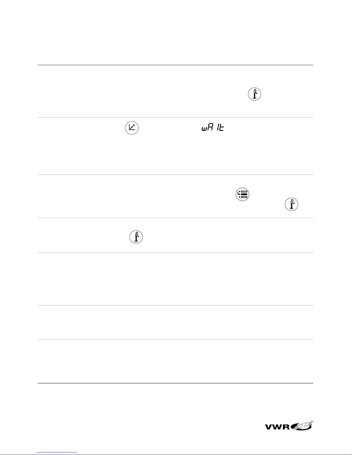
42
sympHony™ Meter User Guide
General Troubleshooting
Problem: The display freezes and the measurement values will not change.
Solution: The meter is in the AUTO-READ measurement mode (the AR icon will
appear in the top, right corner of the display). Press
to start a new
measurement or set the meter to the continuous measurement mode
in the setup menu.
Problem: When I press the meter displays .
Solution: The meter is printing and cannot enter the calibration mode until the
printing is complete. This should rarely occur if the meter is set to
a 9600 baud rate. If the meter is at a lower baud rate, the delay will
be longer.
Problem: The meter did not accept the change I made in the setup menu.
Solution: After making a change in the setup menu, press
until the arrow
icon points to the top line (confirms the change) and then press to
save the change and return to the measurement mode.
Problem: How do I abort a calibration?
Solution: Press and hold
to abort any meter operation and return to the
measurement mode.
Problem: The printout is a string of numbers and units with commas.
Solution: The output format in the setup menu is set to the computer output.
Change the output format to the printer output in the setup menu.
The printer baud rate is set incorrectly in the setup menu. Change the
baud rate to the correct value for the printer that is being used.
Problem: When I press the stirrer button, the stirrer doesn’t work.
Solution: The current stirrer setting is off. Set the speed to 1 through 7 in the
setup menu.
Problem: The timed reading time entry screen does not appear in the
setup menu.
Solution: The meter is in the AUTO-READ or continuous mode. When the meter
is set to the timed mode, the next setup screen will be for time entry.
Trou bl esho ot in g
Page 57

43
sympHony™ Meter User Guide
pH Troubleshooting
Problem: The meter does not recognize the pH buffer value during calibration.
Solution: Verify that the correct buffer set was selected in the setup menu. The
meter uses the raw mV reading of the electrode to recognize a buffer
during calibration. As the electrode ages or becomes dirty, its mV
readings will drift and you may need to manually enter the pH buffer
value when calibrating.
ISE Troubleshooting
Problem: It takes several minutes for the readings to stabilize during a calibration.
Solution: The concentration range in the setup menu is set to low. Change the
concentration range to high.
The ISE resolution is set to 3 digits in the setup menu. Change the ISE
resolution to 2 digits for faster stabilization of the readings.
Problem: When I use the automatic blank correction setting and calibrate an ISE,
the meter gives a slope that is too low or cannot be manually checked.
Solution: Turn the automatic blank correction setting off in the setup menu.
Conductivity Troubleshooting
Problem: The meter does not recognize the conductivity standard during
calibration.
Solution: Verify that the default cell constant was entered in the setup menu. The
cell constant is usually printed on the conductivity probe cable. Verify
that the conductivity standard is one that is programmed into the meter.
Re-calibrate with a fresh standard.
Problem: The temperature coefficient value does not appear in the setup menu.
Solution: The current temperature compensation setting is nonlinear or off.
Change the temperature compensation to linear and the next screen will
be the temperature coefficient value entry screen.
Problem: The measurement is out of range when it should be in range.
Solution: Check that the conductivity probe is fully immersed in the solution.
Verify that the cell constant is correct for the conductivity probe that is
connected to the meter. Verify that the cell type selected in the setup
menu is set to Std.
Trou bl esho ot in g
Page 58

44
sympHony™ Meter User Guide
Dissolved Oxygen Troubleshooting
Problem: The manual barometric pressure entry screen does not appear in the
setup menu.
Solution: The barometric pressure compensation is set to automatic in the setup
menu. Change the barometric pressure compensation to manual and
the next screen will be the manual pressure entry screen.
Problem: The manual salinity factor entry screen does not appear in the
setup menu.
Solution: The salinity correction is set to automatic in the setup menu. Change
the salinity correction to manual and the next screen will be the salinity
factor entry screen.
Problem: The AUTO-STIR BOD probe does not turn on when the button on the
probe is pressed.
Solution: The read type must be set to AUTO-READ in the setup menu and the
stirrer speed must be set from 1 to 7 to initiate a measurement and
start stirring by pressing the button on the AUTO-STIR BOD probe.
Assistance
After troubleshooting all components of your measurement system, contact
Tech ni ca l Su pp or t at 1- 80 0-V WR -S UP P. For the most current contact information,
visit www.vwr.com.
Warranty
For the most current warranty information, visit www.vwr.com.
Trou bl esho ot in g
Page 59

45
sympHony™ Meter User Guide
Chapter XIII
Meter Specifications
Meter Specifications
Portable and Benchtop Meter Environmental Operating Conditions
Operating Ambient Temperature 5 to 45 °C
Operating Relative Humidity 5 to 85 %, non-condensing
Storage Temperature -20 to +60 °C
Storage Relative Humidity 5 to 85 %, non-condensing
Pollution Degree 2
Overvoltage Category II
Altitude Up to 2000 meters
Weight Portable: 0.45 kg
Benchtop: 0.91 kg
Size Portable: 4.8 cm (H) x 9.7 cm (W) x 21.3 cm (D)
Benchtop: 9.4 cm (H) x 17.0 cm (W) x 22.4 cm (D)
AC Powered Meters Indoor use only
Battery Operated Meters Indoor or outdoor use
Regulatory and Safety CE, CSA, TÜV, UL, FCC Class limits
Case Material ABS
Shock and Vibration Vibration, shipping/handling per ISTA #1A
Shock, drop test in packaging per ISTA #1A
Enclosure (designed to meet) IP67 (portable meter)
IP54 (benchtop meter)
Page 60

46
sympHony™ Meter User Guide
Universal Power Adapter Environmental Operating Conditions
Operating Ambient Temperature 0 to 50 °C
Operating Relative Humidity 0 to 90 %, non-condensing
Storage Temperature -20 to +75 °C
Storage Relative Humidity 0 to 90 %, non-condensing
Pollution Degree 2
Overvoltage Category II
Operating Altitude Up to 2000 meters
Benchtop Meters Indoor use only
Meter Parameter Specifications
The following specifications are for the complete line of sympHony meters. Single
and dual parameter meters will not include all of the parameters listed here.
pH
Range -2.000 to 19.999
Resolution 0.1, 0.01, 0.001
Relative Accuracy ± 0.002
Calibration Points 1 to 5
Millivolts, Relative Millivolts, ORP
Range ± 1999.9 mV
Resolution 0.1 mV
Relative Accuracy ± 0.2 mV or 0.05 % of reading, whichever is greater
ISE
Range 0 to 19999
Resolution 1 to 3 significant figures
Relative Accuracy ± 0.2 mV or 0.05 %, whichever is greater
Displayed Units M, mg/L, %, ppb or no units
Calibration Features Linear point to point, selectable non-linear automatic blank
correction and low concentration range stability
Meter Specifications
Page 61

47
sympHony™ Meter User Guide
Dissolved Oxygen
Range 0.00 to 90.0 mg/L
0.0 to 600 %
Resolution 0.1, 0.01 mg/L
0.1, 1 %
Relative Accuracy ± 0.2 mg/L
± 2 %
Salinity Factor 0 to 45 ppt
Barometric Pressure 450 to 850 mm Hg
Calibration Types Water saturated air, air saturated water, manual (Winkler), zero point
Probe Type Polarographic
Conductivity
Range 0.000 to 3000 mS/cm, auto-resolution with cell constant dependence
Resolution 4 significant figures down to 0.001 µS/cm, cell constant dependant
Relative Accuracy 0.5 % ± 1 digit or 0.01 µS/cm, whichever is greater
Cell Constant 0.001 to 199.9 cm
-1
Reference Temperature 15 °C, 20 °C or 25 °C
Resistivity Range 0.0001 to 100 Megohm
Resistivity Resolution Automatic
Resistivity Relative Accuracy 0.5 % ± 1 digit
Salinity Range 0.1 to 80.0 ppt NaCl equivalent, 0.1 to 42 ppt practical salinity
Salinity Resolution 0.1 ppt
Salinity Relative Accuracy 0.1 ± 1 digit
TDS Range 0 to 19999 mg/L
TDS Resolution 1 mg/L
TDS Relative Accuracy 0.5 % ± 1 digit
Temperature
Range -5 to 105 °C
Resolution 0.1 up to 99.9 °C, 1.0 over 99.9 °C
Relative Accuracy ± 0.1 °C
Meter Specifications
Page 62

48
sympHony™ Meter User Guide
Ordering Information
VWR Cat. No. Description
11388-354 SB70P benchtop pH meter with universal power adapter and user guide
11388-368 SB70P benchtop pH meter with refillable pH electrode (14002-850), universal power
adapter and user guide
11388-326 SP70P portable pH meter with batteries and user guide
11388-340 SP70P portable pH meter with gel-filled 3-in-1 pH/ATC electrode (14002-860),
batteries and user guide
11388-350 SB70D benchtop DO meter with universal power adapter and user guide
11388-364 SB70D benchtop DO meter with DO probe (11388-374), universal power adapter and
user guide
11388-322 SP70D portable DO meter with batteries and user guide
11388-336 SP70D portable DO meter with DO probe (11388-374), batteries and user guide
11388-352 SB70C benchtop conductivity meter with universal power adapter and user guide
11388-366 SB70C benchtop conductivity meter with conductivity probe (11388-372), universal
power adapter and user guide
11388-324 SP70C portable conductivity meter with batteries and user guide
11388-338 SP70C portable conductivity meter with conductivity probe (11388-372), batteries
and user guide
11388-348 SB80PI benchtop pH/ISE meter with universal power adapter and user guide
11388-362 SB80PI benchtop pH/ISE meter with refillable pH electrode (14002-850), universal
power adapter and user guide
11388-320 SP80PI portable pH/ISE meter with batteries and user guide
11388-334 SP80PI portable pH/ISE meter with gel-filled 3-in-1 pH/ATC electrode (14002-860),
batteries and user guide
11388-344 SB80PD benchtop pH/DO meter with universal power adapter and user guide
11388-358 SB80PD benchtop pH/DO meter with refillable pH electrode (14002-850), DO probe
(11388-374), universal power adapter and user guide
Meter Specifications
Page 63

49
sympHony™ Meter User Guide
VWR Cat. No. Description
11388-316 SP80PD portable pH/DO meter with batteries and user guide
11388-330 SP80PD portable pH/DO meter with gel-filled 3-in-1 pH/ATC electrode (14002-860),
DO probe (11388-374), batteries and user guide
11388-346 SB80PC benchtop pH/conductivity meter with universal power adapter and user
guide
11388-360 SB80PC benchtop pH/conductivity meter with refillable pH electrode (14002-850),
conductivity probe (11388-372), universal power adapter and user guide
11388-318 SP80PC portable pH/conductivity meter with batteries and user guide
11388-332 SP80PC portable pH/conductivity meter with gel-filled 3-in-1 pH/ATC electrode
(14002-860), conductivity probe (11388-372), batteries and user guide
11388-342 SB90M5 benchtop pH/ISE/DO/conductivity meter with universal power adapter and
user guide
11388-356 SB90M5 benchtop pH/ISE/DO/conductivity meter with Posi-pHlo
™
pH electrode
(14002-782), DO probe (87000-086), conductivity probe (11388-382), universal power
adapter and user guide
11388-314 SP90M5 portable pH/ISE/DO/conductivity meter with batteries and user guide
11388-328 SP90M5 portable pH/ISE/DO/conductivity meter with 3-in-1 pH/ATC electrode
(14002-860), DO probe (11388-374), conductivity probe (11388-372), batteries and
user guide
14002-756 Electrode stand and holder
87000-060 Universal power adapter
87000-090 Stirrer probe with paddle for benchtop meters
11388-400 Printer with printer interface cable (VWR Cat. No. 250302-001)
87000-066 21CFR Part 11 software with computer interface cable (VWR Cat. No. 14004-322)
87000-062 RS232 computer interface cable and RS232 printer interface cable
11388-388 Rugged hard field case for portable meters
11388-402 Soft field case for portable meters
87000-074 Impact jacket with electrode storage sleeve for portable meters
87000-076 Electrode storage sleeve for portable meters
Meter Specifications
Page 64

50
sympHony™ Meter User Guide
VWR Cat. No. Description
14002-850 Refillable combination pH electrode with glass body
14002-780 Refillable combination pH electrode with epoxy body
14002-782 Posi-pHlo
™
clog-resistant combination pH electrode with glass body
14002-784 Posi-pHlo™ clog-resistant combination pH electrode with epoxy body
14002-764 Low-maintenance gel-filled pH electrode with epoxy body
14002-860 Low-maintenance gel-filled 3-in-1 pH/ATC electrode with epoxy body
11388-378 ATC probe with epoxy body
11388-380 ATC probe with glass body
14002-794 Ammonia combination ion selective electrode
14002-786 Chloride combination ion selective electrode
14002-788 Fluoride combination ion selective electrode
14002-796 Nitrate half-cell ion selective electrode (requires a double junction reference
electrode, VWR Cat. No. 14002-854)
14002-790 Silver sulfide combination ion selective electrode
11388-374 DO probe with calibration sleeve and 3 meter cable
87000-086 Rugged DO probe with 1.5 meter cable
87000-088 Rugged DO probe with 3 meter cable
11388-370 BOD AUTO-STIR DO probe with calibration sleeve
87000-092 Conductivity probe, K = 0.1, with 0.01 µS/cm to 300 µS/cm range and 1 meter cable
11388-372 Conductivity probe, K = 1.0, with 1 µS/cm to 20 mS/cm range and 1 meter cable
11388-376 Conductivity probe, K = 1.0, with 10 µS/cm to 200 mS/cm range and 3 meter cable
11388-382 Conductivity probe, K = 0.55, with 1 µS/cm to 200 mS/cm range and 1.5 meter cable
11388-384 Conductivity probe, K = 0.55, with 1 µS/cm to 200 mS/cm range and 3 meter cable
14002-856 Posi-pHlo
™
clog-resistant combination ORP/redox electrode with epoxy body
14002-858 Refillable combination ORP/redox electrode with glass body
Visit www.vwr.com for additional meter kits, accessories, electrodes and solutions.
Meter Specifications
Page 65

51
sympHony™ Meter User Guide
Appendix A
Special Meter Setup Menu Features
pH Setup Menu Features
Automatic buffer recognition
The sympHony pH meters are capable of automatically recognizing pH 1.68, 4.01,
6.86, 7.00, 9.18, 10.01 and 12.46 buffers during a pH calibration. During a calibration,
the meter uses the selected buffer set and the raw mV reading of the pH electrode
in the buffer to recognize and display the buffer value at the measured temperature.
The raw mV value must be about ± 30 mV from the theoretical mV reading of the
buffer in order for the meter to automatically recognize the buffer.
Buffer mV Range Buffer mV Range Buffer mV Range
1.68 +285 to +345 7.00 - 30 to + 30 10.01 -207 to -147
4.01 +207 to +147 9.18 -99 to -159 12.46 -293 to -353
6.86 +38 to -22
Dissolved Oxygen Setup Menu Features
Barometric Pressure Compensation
The sympHony dissolved oxygen meters have an internal barometer that is used for
pressure compensated dissolved oxygen readings. The meter can also use manual
barometric pressure compensation if dissolved oxygen is being measured with a
submerged probe or in a pressurized vessel. The pressure must be entered as mm
Hg (mercury). 1 mm Hg = 0.03937 inch Hg = 1.3332 hPa (mBar) = 0.01934 PSI.
Salinity Correction
Automatic salinity correction for dissolved oxygen readings is available on sympHony
dissolved oxygen meters that have a conductivity mode. The meter uses the
conductivity value read by the conductivity probe to calculate the salinity correction
factor and applies the factor to dissolved oxygen readings reported as mg/L.
Page 66

52
sympHony™ Meter User Guide
The meter can also use manual salinity correction for dissolved oxygen readings
reported as mg/L. The manual salinity correction factor must be entered as ppt
(parts per thousand).
Conductivity
at 20 °C
(mS/cm)
Salinity
Correction
Value (ppt)
Conductivity
at 20 °C
(mS/cm)
Salinity
Correction
Value (ppt)
Conductivity
at 20 °C
(mS/cm)
Salinity
Correction
Value (ppt)
5 3 20 13 35 25
6 4 21 14 36 25
7 4 22 15 37 26
8 5 23 15 38 27
9 6 24 16 39 28
10 6 25 17 40 29
11 7 26 18 42 30
12 8 27 18 44 32
13 8 28 19 46 33
14 9 29 20 48 35
15 10 30 21 50 37
16 10 31 22 52 38
17 11 32 22 54 40
18 12 33 23 56 42
19 13 34 24
This table was calculated from the International Oceanographic Tables, Vol. 1, National Institute of Oceanography
of Great Britain, Womley, Godaming, Surrey, England and Unesco, Paris 1971.
Conductivity Setup Menu Features
Temperature Compensation and Reference Temperature
The sympHony conductivity meters have the ability to use a temperature
compensation feature that calculates and displays the conductivity measurements
at a reference temperature of 15 °C, 20 °C or 25 °C. The temperature compensation
can be set as linear for most aqueous samples, non-linear for ultra pure and low
ionic strength samples or off for non-temperature compensated conductivity
measurements. The closer the sample temperature is to the selected reference
temperature, the more accurate the conductivity measurement will be, especially if
the temperature compensation coefficient is estimated or inaccurate.
Special Meter Setup Menu Features
Page 67

53
sympHony™ Meter User Guide
The conductivity of a solution with a specific electrolyte concentration changes with
temperature and this relationship is described by the temperature coefficient of the
solution. The meter has a default temperature coefficient of 2.1 percent change in
conductivity per ˚C, which is representative of many aqueous samples.
Solution (25 °C to 50 °C) Temperature Coefficient (% / °C)
Ultra Pure Water 4.55
Salt (NaCl) 2.12
5% NaOH 1.72
Dilute Ammonia 1.88
10% HCl 1.32
5% Sulfuric Acid 0.96
98% Sulfuric Acid 2.84
Sugar Syrup 5.64
Total Dissolved Solids (TDS)
The sympHony conductivity meters measure TDS as the total amount of dissolved
inorganics in a solution. The dissolved inorganics carry a current that is measured
by the conductivity probe. Since there is a direct relationship between conductivity
and TDS, conductivity readings are used to estimate the presence of inorganics.
The user must enter a TDS factor between 0.01 an d 10 m g/L in the se tup menu.
The standard method of determining TDS involves evaporating a sample to dryness
at 180 ˚C and weighing the residue. The TDS factor is calculated by taking the
residue weight and dividing it by the sample conductivity. Subsequent conductivity
readings are multiplied by the TDS factor to determine the TDS value of the sample.
Automatic Calibration
The sympHony conductivity meters are capable of automatically recognizing
100 µS/cm, 1413 µS/ cm and 12.9 mS/cm conductivity standards when the nominal
cell constant of the conductivity probe is entered in the setup menu. For the meter
to recognize the conductivity standard, the entered cell constant must be accurate
within a factor of 3. For example, if the actual cell constant is 1.0 cm-1, entering a
nominal cell constant in the range of 0.3 cm-1 to 3.0 cm-1 would allow the meter to
identify the conductivity standard and perform the automatic calibration.
Special Meter Setup Menu Features
Page 68

54
sympHony™ Meter User Guide
ISE Setup Menu Features
Concentration Range
The sympHony ISE meters can be set for a high or low ISE concentration range that
is used to determine the calibration stability criteria. If a high ISE concentration
range is selected, the meter will perform a normal calibration with no delay in
displaying the calibration standard value. If a low ISE concentration range is
selected, the meter will wait about three to five minutes before displaying a stable
reading for the calibration standard values. The delay will depend on the species
being measured and the concentration of the calibration standards. The low ISE
concentration range is designed to improve the accuracy of low concentration
measurements by allowing the electrode to have a longer amount of time to
stabilize in the calibration standards.
Automatic Blank Correction
The sympHony ISE meters have an ISE automatic blank correction feature that
uses an algorithm to compensate for the non-linearity of the ion selective electrode
in low-level standards and samples. Since the automatic blank correction feature
requires the use of a set of non-linear equations that can only be calculated
numerically, the user cannot analytically verify the calibration and the average slope
value that is displayed on the meter may be outside of the slope range that is
specified in the electrode user guide. In applications were analytical verification is
required, the automatic blank correction feature should be turned off.
Special Meter Setup Menu Features
Page 69

254503-001 Rev. B
Page 70

Cotter Corporation (N.S.L.)
Cañon City Milling Facility
Cañon City, Colorado
Procedure
Vegetation Sampling
Number: SOP-E-060
Page 1 of 7
Revision: 1
Date: --/--/--
APPROVAL PAGE
VEGETATION SAMPLING
APPROVALS
Environmental Coordinator:
Date:
Program Manager:
Date:
QA Manager:
Date:
Page 71

Cotter Corporation (N.S.L.)
Cañon City Milling Facility
Cañon City, Colorado
Procedure
Vegetation Sampling
Number: SOP-E-060
Page 2 of 7
Revision: 1
Date: --/--/--
1.0 PURPOSE
This procedure provides the methods for the collection, analysis, and reporting of
vegetation samples in and around the Cotter Corporation (N.S.L.) (“Cotter”), Cañon City
Milling Facility.
2.0 SCOPE
This procedure applies to vegetation samples collected during the growing season near
the three highest predicted environmental air monitoring locations taken by personnel of
the Cotter Cañon City Milling Facility.
3.0 REFERENCES
3.1. Current Colorado Radioactive Materials License.
3.2. Quality Assurance Project Plan (QAPP), current version.
3.3. SOP-E-044, Sampling Equipment Decontamination
3.4. SOP-E-160, Sample Handling and Tracking
3.5. APPENDICES
3.5.1. Sample Transmittal and Tracking Form (SSTF).
3.5.2. Routine Sample Analysis Table
3.6. EXHIBITS
3.6.1. None.
4.0 DEFINITIONS
4.1. Sample Submittal And Tracking Form (SSTF): method of initiating, tracking,
and documenting all samples taken at the Cotter, Cañon City Milling Facility via
the Laboratory Information Management System (LIMS).
4.2. Laboratory Information Management System (LIMS): method setup by
Cotter, Cañon City Milling Facility for tracking and documenting information
pertinent to samples and other information.
4.3. Field Staff: the sampling technician or other qualified individual designated by
the Environmental Coordinator (EC).
5.0 EQUIPMENT AND MATERIALS
Page 72

Cotter Corporation (N.S.L.)
Cañon City Milling Facility
Cañon City, Colorado
Procedure
Vegetation Sampling
Number: SOP-E-060
Page 3 of 7
Revision: 1
Date: --/--/--
5.1. EQUIPMENT
5.1.1. Pruning shears/scissors.
5.1.2. Suitable clean container for sample storage.
5.1.3. Lab type weighing scale
5.2. MATERIALS
5.2.1. Nalgene® plastic bag or equivalent containers
5.2.2. Latex gloves
5.2.3. Decontamination supplies and solutions listed in SOP-E-044
5.3. MAINTENANCE/CALIBRATION
5.3.1. None for this procedure
6.0 HEALTH AND SAFETY
6.1. When sampling, precautions should be taken to avoid possible chemical hazards
from crop treatment, i.e., pesticides, herbicides, and fertilizers. In addition, it
would benefit the samplers to be familiar with and avoid contact with plants that
present a contact hazard such as poison ivy.
6.2. Latex gloves are worn to minimize skin contact with plants and soil.
7.0 RESPONSIBILITY
7.1. The Quality Assurance Manager is responsible for:
7.1.1. Administering principals to assure adherence to procedures found in the
QAPP current version.
7.2. The Environmental Coordinator (EC) is responsible for:
7.2.1. Providing the locations for the vegetation samples based on information
obtained from other monitoring sources in and around the milling facility.
7.2.2. Ensuring that the field staff technicians obtaining vegetation samples are
properly trained.
7.3. The Field Staff are responsible for:
Page 73

Cotter Corporation (N.S.L.)
Cañon City Milling Facility
Cañon City, Colorado
Procedure
Vegetation Sampling
Number: SOP-E-060
Page 4 of 7
Revision: 1
Date: --/--/--
7.3.1. Having all necessary equipment and supplies prior to going to the field to
obtain samples.
7.3.2. Advising the EC of any deviations from planned activities or problems
encountered during sampling events.
7.3.3. Following this procedure.
8.0 INSTRUCTIONS
8.1. Grass vegetation will be sampled three times during the growing season at
locations determined by the EC. Sample locations will be determined by the
highest predicted contaminant concentrations as determined by the most recent
offsite dose assessment information.
8.2. The Field Staff technician will receive the sampling locations from the EC.
8.3. Collect samples of non-woody forbs, grasses, and/or cultivated vegetation.
Vegetation will be severed using scissors or pruning shears no closer than 5 cm
from the point where the plant emerges from the soil to avoid soil contamination.
8.4. A sufficient volume of sample will be taken and placed in a Nalgene® bag, an
equivalent plastic bag or container.
8.4.1. Collect approximately 1000 grams wet sample weight. This may not
always be possible due to vegetation conditions caused by drought etc.
8.5. Label the sample bag using an indelible marker with the location, date, and time
the sample was taken, field weight of sample and the SSTF#.
8.6. Note pertinent information in the field sampling logbook or equivalent, including
the location, date and time of sample, description of sample location, site
conditions, weight of sample, and any unusual circumstances encountered during
the sampling effort.
8.7. Clean sampling equipment following SOP-E-044 before proceeding to the next
sample location.
8.8. Continue sampling until samples at all locations have been taken.
8.9. For quality assurance purposes a duplicate sample will be collected at one of the
sampling locations.
8.9.1. For the QA sample, collect double the amount or volume as for the regular
sample.
Page 74

Cotter Corporation (N.S.L.)
Cañon City Milling Facility
Cañon City, Colorado
Procedure
Vegetation Sampling
Number: SOP-E-060
Page 5 of 7
Revision: 1
Date: --/--/--
8.9.2. Place the collected vegetation in to a large clean plastic bag or other
suitable clean container, mix to blend the sample.
8.9.3. Place the blended vegetation in to two sample bags. Label one as the
regular sample and the other as the QA duplicate sample.
8.10. After arriving back at the facility, complete the required paperwork and SSTF
form. Transfer sample custody to the laboratory for processing and analysis per
SOP-E-160.
9.0 RECORDS
9.1. Field sampling logbook, field data sheet, or tablet.
9.2. Analysis report
Page 75

Cotter Corporation (N.S.L.)
Cañon City Milling Facility
Cañon City, Colorado
Procedure
Vegetation Sampling
Number: SOP-E-060
Page 6 of 7
Revision: 1
Date: --/--/--
Appendix 3.5.1
Sample Submittal and Tracking Form (SSTF)
Page 76
Cotter Corporation (N.S.L.)
Cañon City Milling Facility
Cañon City, Colorado
Procedure
Vegetation Sampling
Number: SOP-E-060
Page 7 of 7
Revision: 1
Date: --/--/--
Appendix 3.5.2 Sample Analysis Table
Matrix
Analysis
Anticipated
Concentration
Range
Analytical
Method
Laboratory
ID
Sample
Type
Sample
Number
Field
Duplicates
Holding Tme
Lab
Turnaround
Time
Data
Use
Sample Volume
Container
Type
Preservative
Field
Filtered
Total
Analysis
Vegetation
Natural Uranium
6 - 102 pCi/kg
EPA
Method
6020A
Cotter
Grab 9 3
6 months
90 days
RML
1 kg field weight
ZipLock
Bag or
glass jar
NA
NA
12
Molybdenum
0.8 - 53 mg/kg
No
established
holding time,
analyze as
soon as
feasible
90 days
RML
1 kg field weight
Thorium 230
10 - 132 pCi/kg
EPA
Method
910
1 kg field weight
ZipLock
Bag or
glass jar
NA
NA
Raduim 226
25 - 210 pCi/kg
EPA
Method
903
Thorium 232
1 - 6 pCi/kg
EPA
Method
910
Lead 210
46 - 210 pCi/kg
EPA
Method
901
Page 77

Cotter Corporation (N.S.L.)
Cañon City Milling Facility
Cañon City, Colorado
Procedure
Environmental
Thermoluminescent
Dosimetry
Number: SOP-E-070
Page 1 of 8
Revision: 1
Date: --/--/--
APPROVAL PAGE
ENVIRONMENTAL THERMOLUMINESCENT DOSIMETRY
APPROVALS
Environmental Coordinator:
Date:
Program Manager:
Date:
QA Manager:
Date:
Page 78

Cotter Corporation (N.S.L.)
Cañon City Milling Facility
Cañon City, Colorado
Procedure
Environmental
Thermoluminescent
Dosimetry
Number: SOP-E-070
Page 2 of 8
Revision: 1
Date: --/--/--
1.0 PURPOSE
The purpose of this procedure is to provide the methods for the collection, analysis, and
reporting of environmental exposure rates in and around the Cotter Corporation (N.S.L.)
(“Cotter”), Canon City Milling Facility and to comply with the current Colorado
Radioactive Materials License.
2.0 SCOPE
This procedure applies to all environmental Thermoluminescent Dosimeters (“TLD”)
distributed and collected for evaluation of the surrounding areas of the milling facility to
determine exposure to the environment and public.
3.0 REFERENCES
3.1 REFERENCES
3.1.1 Current Colorado Radioactive Materials License.
3.1.2 Quality Assurance Project Plan (QAPP), current version.
3.2 APPENDICES
3.2.1 Sample Locations for Environmental Thermoluminescent Dosimetry
3.2.2 Routine Sample Analysis Table
3.3 EXHIBITS
3.3.1 Sample Replacement Data Sheet for TLD, RSD-17.
3.3.2 Environmental, Inc. Midwest Laboratories TLD Data Sheet.
4.0 DEFINITIONS
4.1 TLD: a dosimeter which provides personal dose interpretation of beta, x-ray, and
higher energy photon.
4.2 Field Staff: the sample technician or other qualified individual designated by the
Environmental Coordinator (EC).
5.0 EQUIPMENT AND MATERIALS
5.1 EQUIPMENT
Page 79

Cotter Corporation (N.S.L.)
Cañon City Milling Facility
Cañon City, Colorado
Procedure
Environmental
Thermoluminescent
Dosimetry
Number: SOP-E-070
Page 3 of 8
Revision: 1
Date: --/--/--
5.1.1 Staple gun and staples
5.1.2 Ziplock type plastic bags or the equivalent
5.2 MATERIALS
5.2.1 Thermoluminescent dosimetry badges (TLD).
5.3 MAINTENANCE/CALIBRATION
5.3.1 None for this procedure
6.0 HEALTH AND SAFETY
6.1 Standard worker safety personal protective equipment (PPE) should be observed
when using this procedure.
6.2 In the warmer months be aware of the possibility of snakes and stinging insects.
7.0 RESPONSIBILITY
7.1 The Quality Assurance Manager (QA Manager) is responsible for:
7.1.1 Administering principals to assure adherence to procedures and policies
found in the QAPP current version.
7.2 The EC is responsible for:
7.2.1 Ensuring the field staff sample technician(s) are properly trained.
7.2.2 Reviewing analysis of the TLD to determine any corrective actions that
need to be taken if necessary.
7.3 The field staff sample technician is responsible for:
7.3.1 Having all necessary materials and supplies prior to going to the TLD
sample stations for retrieval and replacement.
7.3.2 Advising the EC of any deviations from the planned activities or problems
encountered during sample TLD recovery or installation that may affect
analysis results.
7.3.3 Following instructions as outlined in this procedure.
8.0 INSTRUCTIONS
Page 80

Cotter Corporation (N.S.L.)
Cañon City Milling Facility
Cañon City, Colorado
Procedure
Environmental
Thermoluminescent
Dosimetry
Number: SOP-E-070
Page 4 of 8
Revision: 1
Date: --/--/--
8.1 FREQUENCY
8.1.1 Unexposed TLD will replace exposed TLD quarterly as determined by the
EC or by conditions set forth in the current Colorado Radioactive
Materials license.
8.1.1.1 A duplicate TLD (QA) will be placed at one location on a
rotating basis to verify results of that TLD.
8.1.1.2 Additionally a control TLD is located at the residence of the EC
during the exposure period.
8.1.1.2.1 The control TLD will be placed in a lead shielded
box to insure that it is not exposed to ionizing
radiation during the sample period.
8.1.1.2.2 Sample media will be placed at locations listed in
Appendix 3.2.1.
8.2 PROCEDURE
8.2.1 The EC receives the TLD at his residence from the dosimetry vendor and
places the replacement control TLD in a lead shielded container at his
residence during the sampling period.
8.2.2 The dosimetry TLD are provided to the field sample staff for exchange
and collection.
8.2.3 The field staff technician at each monitoring location will place the TLD
into a Ziploc® type bag or equivalent and upon arrival at the monitoring
location place the TLD at the height of a human torso to simulate whole
body exposure.
8.2.4 The field staff technician, on arriving back at the facility will complete all
necessary paperwork and package the exchanged TLD badges and the
control TLD for the previous quarter for shipment to the dosimerty vender
for processing.
9.0 RECORDS
9.1 TLD dosimerty analysis report
Page 81

Cotter Corporation
Canon City Milling Facility
Canon City, Colorado
Procedure
Environmental
Thermoluminescent
Dosimetry
Number: SOP-E-070
Page: 5 of 8
Revision: 1
Date: April 2016
Appendix 3.2.1
Sample Locations for Environmental Thermoluminescent Dosimetry
Location
ATI Location
Number
Cotter Location Description
Quality Control
QC-1
E. Qtr. Corner Sec. 16
C-2
AS-202
S. Qtr. Corner Sec. 16
C-3
AS-203
W. Qtr. Corner Sec. 16
C-4
AS-204
Lincoln Park
C-5
LP-2
Canon City
C-6
CC-2
OroVerde
COV-3
OV-3
North Boundary
CAS-206
AS-206
Mill Entrance Rd.
AS-209
AS-209
Shadow Hills Estate
SH-ES-210
AS-210
Nearest Resident
N.R. 212
AS-212
Page 82
Cotter Corporation
Canon City Milling Facility
Canon City, Colorado
Procedure
Environmental Thermoluminescent Dosimetry
Number: SOP-E-070
Page: 6 of 8
Revision: 1
Date: April 2016
Appendix 3.2.2 Routine Sample Analysis Table
Matrix
Analysis
Anticipated
Concentration
Range
Cotter SOP
Analytical Method
Laboratory ID
Sample Type
Sample
Number
Field
Duplicates
Holding
Tme
Lab
Turnaround
Time
Data Use
Sample
Volume
Container
Type
Preservative
Env Gamma
Gamma
10-17 uR/hr
SOP-E-070
(SOP) EIML-TLD-01
ATI-EIML
Continuous
(90 Days)
40
4
Analyze
as soon
as
feasible
30 days
RML
NA
TLD
(CaSO4 :Dy)
NA
Page 83

Cotter Corporation
Canon City Milling Facility
Canon City, Colorado
Procedure
Environmental
Thermoluminescent
Dosimetry
Number: SOP-E-070
Page: 7 of 8
Revision: 1
Date: April 2016
Exhibit 3.3.1
Page 84

Cotter Corporation
Canon City Milling Facility
Canon City, Colorado
Procedure
Environmental
Thermoluminescent
Dosimetry
Number: SOP-E-070
Page: 8 of 8
Revision: 1
Date: April 2016
Exhibit 3.3.2
Page 85

Cotter Corporation (N.S.L.)
Cañon City Milling Facility
Cañon City, Colorado
Procedure
Arkansas River Water
Sample Collection
Number: SOP-E-090
Page: 1 of 9
Revision: 1
Date: --/--/--
APPROVAL PAGE
ARKANSAS RIVER WATER SAMPLE COLLECTION
APPROVALS
Environmental Coordinator:
Date:
Program Manager:
Date:
QA Manager:
Date:
Page 86

Cotter Corporation (N.S.L.)
Cañon City Milling Facility
Cañon City, Colorado
Procedure
Arkansas River Water
Sample Collection
Number: SOP-E-090
Page: 2 of 9
Revision: 1
Date: --/--/--
1.0 PURPOSE
This procedure is to be used when taking water quality samples from the Arkansas River
near the Cotter Corporation (N.S.L.) Cañon City Milling Facility.
2.0 SCOPE
2.1 This procedure applies to samples taken from the Arkansas River at the following
two locations:
2.1.1 Location ID 907 at the intersection of the Arkansas River with First Street,
Cañon City, CO.
2.1.2 Location ID 904 at the intersection of the Arkansas River at McKenzie
Boulevard, also known as Four Mile Road, Cañon City, CO.
2.2 Additionally this procedure applies to any water samples at other locations of the
Arkansas River that are deemed necessary to be taken by the Cotter Corporation
(N.S.L.), Cañon City Milling Facility.
3.0 REFERENCES
3.1 Current Colorado Radioactive Materials License.
3.2 Quality Assurance Project Plan, (QAPP), current version.
3.3 Procedure SOP-E-041, Measurement of pH of Water Samples.
3.4 Procedure SOP-E-042, Measurement of Electrical Conductivity of Water
Samples.
3.5 Procedure SOP-E-044, Sample Equipment Decontamination.
3.6 Procedure SOP-E-160, Sample Handling and Tracking
3.7 EXHIBITS
3.7.1 Field Sample Analysis Table
3.7.2 Sample Transmittal and Tracking Form (SSTF)
4.0 DEFINITIONS
4.1 Field Staff: the sampling technician or other qualified individual designated by
the Environmental Coordinator (EC).
5.0 EQUIPMENT AND MATERIALS
5.1 EQUIPMENT
Page 87

Cotter Corporation (N.S.L.)
Cañon City Milling Facility
Cañon City, Colorado
Procedure
Arkansas River Water
Sample Collection
Number: SOP-E-090
Page: 3 of 9
Revision: 1
Date: --/--/--
5.1.1 Model D74TM integrated depth sampler.
5.1.2 USGS AA Current Meter.
5.1.3 Bucket.
5.1.4 Churnsplitter.
5.1.5 Various booms, rods, cables and winches.
5.1.6 pH meter.
5.1.7 Electrical conductivity meter.
5.1.8 Temperature meter.
5.1.9 Field sampling logbook, field data sheet, or tablet.
5.1.10 Waterproof marking pens.
5.2 MATERIALS
5.2.1 New polyethylene sample bottles.
5.2.2 4,7, and 10 pH buffers.
5.2.3 Appropriate electrical conductivity standards.
5.2.4 SSTF.
5.2.5 Decontamination equipment and supplies, (See Procedure SOP-E-044).
5.3 MAINTENANCE/CALIBRATION
5.3.1 Refer to the specific instruments operating instruction manual for
calibration, troubleshooting and maintenance.
6.0 HEALTH AND SAFETY
6.1 Sample technicians should be certain all mechanical equipment is in good repair
and properly maintained before attempting its use.
6.2 When taking a grab sample care should be taken because rocks along the banks of
the river can be slippery.
6.3 Traffic safety when working near roadways.
Page 88

Cotter Corporation (N.S.L.)
Cañon City Milling Facility
Cañon City, Colorado
Procedure
Arkansas River Water
Sample Collection
Number: SOP-E-090
Page: 4 of 9
Revision: 1
Date: --/--/--
6.4 Acids used for preservation of samples and decontamination of equipment are
potentially dangerous. Read the individual Safety Data Sheet (SDS) for all
chemicals prior to use, storage, and transportation.
6.5 Wear latex gloves and safety glasses when handling acids during decontamination
and sample preservation.
7.0 RESPONSIBILITY
7.1 The QA Manager is responsible for:
7.1.1 Administering principals to assure adherence to procedures and policies
found in the SOP-E-160 and QAPP current version.
7.2 The Environmental Coordinator (EC) is responsible for:
7.2.1 Insuring the field technicians are properly trained and following correct
procedures involving the water quality samples.
7.2.2 Reviewing data from water quality analysis.
7.3 The Field sample technician is responsible for:
7.3.1 Having all necessary materials and supplies prior to going to the assigned
water quality monitoring sites to obtain samples.
7.3.2 Following the directives in the SOP-E-160 for sample handling and chain
of custody.
7.3.3 Following items listed within this procedure.
8.0 INSTRUCTIONS
8.1 Samples will be taken on a quarterly basis as listed in the Radioactive Materials
License or as directed by the EC. Also one QA sample will be taken annually.
The location of the QA sample will be determined by using a random number
generating program.
8.2 After arriving at location at which river will be sampled utilize the Equal Width
Increment (EWI) to determine sample locations by.
8.3 Measure the width of the river and divide into a minimum of twelve equal
segments.
8.4 Measure flow rate of stream using current meter at each segment as defined
above.
8.4.1 If water depth is less than 2.5 feet, measure the current at 60% down from
the surface.
Page 89

Cotter Corporation (N.S.L.)
Cañon City Milling Facility
Cañon City, Colorado
Procedure
Arkansas River Water
Sample Collection
Number: SOP-E-090
Page: 5 of 9
Revision: 1
Date: --/--/--
8.4.2 If water depth is greater than 2.5 feet, measure the current at 80% and 20%
down from the surface.
8.4.3 If water flow is either too low, too high or other conditions prevent
collecting a set flow measurements, document the river flow rate recorded
from the nearest river gauging station after returning the facility office.
8.4.4 Proceed to section 8.11 of this procedure.
8.5 Record the current readings in the field sampling logbook or the equivalent.
8.6 Upon returning to the milling facility, enter appropriate readings into the
computer to ascertain river flow rates. Enter results in field sampling logbook or
the equivalent.
8.7 Begin to obtain the sample by first determining position in the transit and using
the Model D74TM depth integrated sampler.
8.7.1 Select a nozzle from those provided in the kit and install a pre-cleaned 1
liter sample bottle in sampler and lower to pre-determined point in water
column. The lowering and raising of the sampler should be approximately
at the same rate.
8.7.2 Retrieve sampler and inspect to see if bottle has been overfilled. Evidence
of which, will be water flowing from the nozzle.
8.7.3 If sample bottle has been overfilled, empty and repeat sections 8.7.1 and
8.7.2.
8.7.4 Repeat until a good sample is taken.
8.7.5 Pour water sample into churnsplitter.
8.8 Repeat the sections 8.7.2 thru 8.7.5 until all transects have been sampled.
NOTE: If after the above procedure is completed, there is not sufficient volume
of sample to fill all bottles in the sample suite. Resample the entire transect as
many times as necessary to obtain sufficient volume. All transect points must be
sampled if one of them is taken.
8.9 Fill individual bottles for analysis from the churnsplitter.
8.10 Label bottles using waterproof marker with:
8.10.1 Location.
8.10.2 Date.
8.10.3 Sample submittal number.
Page 90

Cotter Corporation (N.S.L.)
Cañon City Milling Facility
Cañon City, Colorado
Procedure
Arkansas River Water
Sample Collection
Number: SOP-E-090
Page: 6 of 9
Revision: 1
Date: --/--/--
8.11 If river flow is either too low, too high or dangerous conditions exist, collect grab
samples from appropriate locations in river.
8.11.1 Begin to obtain sample by selecting locations on both sides of the river
channel for collection of grab samples. When taking a grab sample a
bucket will be used to dip a sufficient amount of water from both sides of
the river and pouring the water into a churnsplitter.
8.12 Fill out SSTF as required.
8.13 Fill out field sampling logbook or equivalent with all necessary information.
8.14 Maintain Chain of Custody per SOP-E-160 and QAPP current version
8.15 Decontaminate equipment using Procedure SOP-E-044.
9.0 RECORDS
9.1 Field sampling logbook, field data sheet, or tablet
Page 91
otter Corporation (N.S.L.)
Cañon City Milling Facility
Cañon City, Colorado
Procedure
Arkansas River Water Sample Collection
Number: SOP-E-090
Page: 7 of 9
Revision: 1
Date: --/--/--
Exhibit 3.7.1
Field Sample Analysis Table
Analysis
Anticipated
Concentration
Range
Cotter SOP
Analytical
Method
Laboratory
ID
Sample
Type
Sample
Number
Field
Duplicates
Holding
Time
Lab
Turnaround
Time
Data
Use
Sample
Volume
Container
Type
Preservative
Field
Filtered
Total
Analysis
Temperature
NA
NA
NA
Field
parameter
Grab
410
20
NA
NA
RML
NA
NA
None
No
430
pH
2.9- 12.3 s.u.
SOP-E-042
NA
Specific Conductance
150 - >20000 uS
SOP-E-041
NA
Oxygen Reduction Potential (ORP)
260 - 702 mv
(SHE)
SOP-E-046
NA
73 4 77
Total Dissolved Solids (TDS)
<10 - 206000
mg/L
EPA Method
160.1
Cotter
Grab
364
18
7 days
90 days
RML
1000 mL
P or G
Cool to
<6°C
No (Lab
filtered)
382
Total Suspended Solids (TSS)
<2 - 350 mg/L
EPA Method
160.2
No
Alkalinity (total as CaCO3)
<1 -880 mg/L
EPA Method
5.10
Cotter
Grab
364
18
14 days
90 days
RML
1000 mL
P or G
Cool to
<6°C
No
382
Bicarbonate (as HCO3)
<1 - 840 mg/L
Carbonate (as CaCO3)
<1 - 750 mg/L
Sulfate
<3 - 140000
mg/L
EPA Method
375.3
28 days
90 days
RML
Cool to
<6°C
No
Chloride
<3 - 15000 mg/L
EPA Method
325.3
Calcium
<0.03 - 630 mg/L
EPA Method
6020A
Cotter
Grab
364
18
6 months
90 days
RML
250 mL
P or G
HNO3 to pH
<2
Yes
382
Magnesium
<0.005 - 17000
mg/L
Potassium
<0.02 - 240 mg/L
Sodium
<0.03 - 41000
mg/L
Nitrate+Nitrite
<0.6- 270 mg/L
SOP-L-4-9
No EPA
Method
Cotter
Grab
402
20
28 days
90 days
RML
125 mL
P or G
H2SO4 to pH
<2
No
422
Page 92
otter Corporation (N.S.L.)
Cañon City Milling Facility
Cañon City, Colorado
Procedure
Arkansas River Water Sample Collection
Number: SOP-E-090
Page: 8 of 9
Revision: 1
Date: --/--/--
Exhibit 3.7.1
Field Sample Analysis Table (continued)
Analysis
Anticipated
Concentration
Range
Cotter
SOP
Analytical
Method
Laboratory
ID
Sample
Type
Sample
Number
Field
Duplicates
Holding
Time
Lab
Turnaround
Time
Data
Use
Sample
Volume
Container
Type
Preservative
Field
Filtered
Total
Analysis
Uranium Suspended
<0.0001 - 4 mg/L
EPA Method
6020A
Cotter
Grab
45
2
6 months
90 days
RML
250 mL
P or G
HNO3 to pH
<2
No
47
Molybdenum Suspended
0.0003 - 0.005
mg/L
8 1 9
Selenium Dissolved
<0.001-1 mg/L
EPA Method
6020A
Cotter
Grab
147
7
6 months
90 days
RML
250 mL
P or G
HNO3 to pH
<2
Yes
154
Iron Dissolved
< 0.001 - 2900
mg/L
402
20
422
Manganese Dissolved
<0.02- 790 mg/L
402
20
422
Molybdenum Dissolved
<0.0001 - 83 mg/L
410
20
422
Uranium Dissolved
<0.0001 - 95 mg/L
410
20
422
Radium 226 Suspended
<0.05-0.3 pCi/l
EPA Method
903
Cotter
Grab
45
2
6 months
90 days
RML
Note: Included
in the amount
for
Radionuclides
Dissolved plus
field sampling
filters
ZipLock
Bag
NA
No (Field
sampling
filters
submitted)
47
Thorium 230 Suspended
<0.1-1.2 pCi/l
EPA Method
910
45 2 47
Lead 210 Suspended
<0.7-4.2 pCi/l
EPA Method
901
37 2 39
Polonium 210 Suspended
<0.2 - 4.3 pCi/l
EPA Method
912
37 2 39
Radium 226 Dissolved
<0.1-1.5 pCi/l
EPA Method
903
Cotter
Grab
45
2
6 months
90 days
RML
4000 mL
P or G
HNO3 to pH
<2
Yes
47
Thorium 230 Dissolved
<0.1-0.3 pCi/l
EPA Method
910
45 2 47
Lead 210 Dissolved
<0.7-3.4 pCi/l
EPA Method
901
37 2 39
Polonium 210 Dissolved
<0.1 - 0.9 pCi/l
EPA Method
912
37 2 39
Page 93

otter Corporation (N.S.L.)
Cañon City Milling Facility
Cañon City, Colorado
Procedure
Arkansas River Water
Sample Collection
Number: SOP-E-090
Page: 9 of 9
Revision: 1
Date: --/--/--
Exhibit 3.7.2
Sample Submittal and Tracking Form (SSTF)
Page 94

Cotter Corporation (N.S.L.)
Cañon City Milling Facility
Cañon City, Colorado
Procedure
Soil Sampling
Number: SOP-E-110
Page 1 of 8
Revision: 1
Date: --/--/--
APPROVAL PAGE
SOIL SAMPLING
APPROVALS
Environmental Coordinator:
Date:
Program Manager:
Date:
QA Manager:
Date:
Page 95

Cotter Corporation (N.S.L.)
Cañon City Milling Facility
Cañon City, Colorado
Procedure
Soil Sampling
Number: SOP-E-110
Page 2 of 8
Revision: 1
Date: --/--/--
1.0 PURPOSE
This procedure provides the methods for the collection, analysis, and reporting of soil
samples in and around the Cotter Corporation, Cañon City Milling Facility.
2.0 SCOPE
This procedure applies only to annual routine soil samples including those for public dose
assessment taken by Cotter Corporation (N.S.L.) (“Cotter”) Cañon City Milling Facility.
3.0 REFERENCES
3.1. Current Colorado radioactive materials license.
3.2. Quality Assurance Project Plan (QAPP), current version.
3.3. Procedure SOP-E-044, Decontamination of Equipment
3.4. Procedure SOP-E-160, Sample Handling and Tracking
3.5. APPENDICES
3.5.1. Sample Transmittal and Tracking Form (SSTF).
3.5.2. Routine Sample Analysis Table
3.5.3. Current Sampling Location Listing
3.6. EXHIBITS
3.6.1. None
4.0 DEFINITIONS
4.1. Sample Submittal And Tracking Form (SSTF): method of initiating, tracking,
and documenting all samples taken at the cotter corporation, Cañon City Milling
Facility via the Laboratory Information Management System (LIMS).
4.2. Field Staff: the sampling technician or other qualified individual designated by
the Environmental Coordinator (EC).
Page 96

Cotter Corporation (N.S.L.)
Cañon City Milling Facility
Cañon City, Colorado
Procedure
Soil Sampling
Number: SOP-E-110
Page 3 of 8
Revision: 1
Date: --/--/--
5.0 EQUIPMENT AND MATERIALS
5.1. EQUIPMENT
5.1.1. Stainless steel metal shovel or stainless steel tube sampler.
5.1.2. Stainless steel mixing bowl and utensils
5.1.3. Field sampling logbook, field data sheet, or tablet.
5.1.4. Hand-held GPS unit.
5.2. MATERIALS
5.2.1. Nalgene® plastic sample bag or the equivalent
5.2.2. Equipment decontamination supplies listed in SOP-E-044.
5.2.3. Sample Transmittal and Tracking Form (SSTF).
5.3. MAINTENANCE/CALIBRATION
5.3.1. None for this procedure
6.0 HEALTH AND SAFETY
6.1. Standard worker safety and handling of equipment should be observed when
using this procedure.
7.0 RESPONSIBILITY
7.1. The Environmental Coordinator (EC) is responsible for:
7.1.1. Ensuring that the field staff technicians obtaining soil samples are properly
trained.
7.1.2. Notifying CDPHE when required prior to sampling.
7.2. The field staff technician is responsible for:
7.2.1. Having all necessary equipment and supplies prior to going to the field to
obtain samples.
7.2.2. Advising the EC of any deviations from planned activities or problems
encountered during sampling events.
7.3. The Quality Assurance Manager (QA Manager) is responsible for:
Page 97

Cotter Corporation (N.S.L.)
Cañon City Milling Facility
Cañon City, Colorado
Procedure
Soil Sampling
Number: SOP-E-110
Page 4 of 8
Revision: 1
Date: --/--/--
7.3.1. Administering principals to assure adherence to procedures and policies
found in the QAPP current version.
8.0 INSTRUCTIONS
8.1. Soil samples will be collected annually or as specified by the EC.
8.2. The field staff will acquire all necessary equipment and materials for the sampling
effort.
8.3. The field staff will take the soil sample at the required locations or where
specified by the EC. When collecting samples, be mindful not to sample at the
exact spot as in previous years. Designate the sampling location GPS coordinates
in the field logbook.
8.4. Latex gloves are worn to protect the sampler from residual contamination on the
hands and minimize cross contamination between samples.
8.5. Remove the top 5 cm of soil from a 10 cm x 10 cm area using the stainless steel
shovel or take a 5 cm diameter plug 5 cm deep if using the soil sampler. Remove
any large rocks or debris from the sample.
8.6. Place the soil in a Nalgene® sample bag or equivalent.
8.7. Label the sample bag or equivalent using an indelible marker or prepared a label
with the location, date, and time the sample was taken and the SSTF #.
8.8. Note pertinent information in the field sampling logbook or equivalent, including
the location, date and time of sample, description of sample location, site
conditions, GPS coordinates, and any unusual circumstances encountered during
the sampling effort.
8.9. Fill out the necessary information on the SSTF.
8.10. Clean the sampling equipment following SOP-E-044 before proceeding to the
next sample location.
8.11. Continue sampling until all samples at all locations have been taken.
8.12. For quality assurance purposes a duplicate sample will be collected at one of the
sampling locations.
8.12.1. For the QA sample, collect double the amount or volume as for the regular
sample.
Page 98

Cotter Corporation (N.S.L.)
Cañon City Milling Facility
Cañon City, Colorado
Procedure
Soil Sampling
Number: SOP-E-110
Page 5 of 8
Revision: 1
Date: --/--/--
8.12.2. Place the collected soil in to a stainless steel bowl and mix to blend the
sample.
8.12.3. Place the blended soil in to two sample bags. Label one as the regular
sample and the other as the QA duplicate sample.
8.13. After arriving back at the facility, complete the required paperwork and SSTF
form. Transfer sample custody to the laboratory for processing and analysis as per
SOP-E-160.
9.0 RECORDS
9.1. Field sampling logbook, field data sheet, or tablet
Page 99

Cotter Corporation (N.S.L.)
Cañon City Milling Facility
Cañon City, Colorado
Procedure
Soil Sampling
Number: SOP-E-110
Page 6 of 8
Revision: 1
Date: --/--/--
Appendix 3.5.1
Sample Submittal and Tracking Form (SSTF)
Page 100
Cotter Corporation (N.S.L.)
Cañon City Milling Facility
Cañon City, Colorado
Procedure
Soil Sampling
Number: SOP-E-110
Page 7 of 8
Revision: 1
Date: --/--/--
Appendix 3.5.2 Routine Sample Analysis Table
Analysis
Anticipated
Concentration
Range
Cotter SOP
Analytical
Method
Laboratory
ID
Sample
Type
Sample
Number
Field
Duplicates
Holding
Time
Lab
Turnaround
Time
Data
Use
Sample
Volume
Container
Type
Preservative
Field
Filtered
Total
Analysis
Natural Uranium
2 -17 pCi/g
EPA
Method
6020A
Cotter
Grab
10
1
6 months
90 days
RML
250 g
ZipLock
Bag or
glass jar
NA
NA
11
Molybdenum
1.1 - 27 ug/g
No
established
holding time,
analyze as
soon as
feasible
90 days
RML
100 g
Thorium 230
2 - 59 pCi/g
EPA
Method 910
Cotter
Grab
100 g
ZipLock
Bag or
glass jar
NA
NA
Radium 226
1 - 13 pCi/g
EPA
Method 903
Thorium 232
0.8 -1.3 pCi/g
EPA
Method 910
Thorium 228
0.7 - 1.3 pCi/g
EPA
Method 910
Radium 224
0.6 - 2.1 pCi/g
EPA
Method 903
Lead 210
1 - 10 pCi/g
EPA
Method 901
 Loading...