

VWR International MU 6100 H Instruction Manual
MULTI meter
6100 H
MU
MU 6100 H
INSTRUCTION MANUAL
European Catalogue Number(s):
MU 6100 H S1: 665-0311
MU 6100 H S2: 665-0312
Version: 2
Issued: September 11, 2014 11:39 am
ba77077e02 09/2014

MU 6100 H
Legal address of manufacturer:
VWR International bvba
Researchpark Haasrode 2020
Geldenaaksebaan 464
B-3001 Leuven
+32 16 385011
http://be.vwr.com
Manufactured in Germany.
2
ba77077e02 09/2014

MU 6100 H Contents
MU 6100 H - Contents
1 Safety . . . . . . . . . . . . . . . . . . . . . . . . . . . . . . . . . . . . . . . . 7
1.1 Safety information . . . . . . . . . . . . . . . . . . . . . . . . . . . . . . . 7
1.1.1 Safety information in the operating manual . . . . . 7
1.1.2 Safety signs on the meter . . . . . . . . . . . . . . . . . . 7
1.1.3 Further documents providing safety information . 7
1.2 Safe operation. . . . . . . . . . . . . . . . . . . . . . . . . . . . . . . . . . 8
1.2.1 Authorized use . . . . . . . . . . . . . . . . . . . . . . . . . . . 8
1.2.2 Requirements for safe operation . . . . . . . . . . . . . 8
1.2.3 Unauthorized use . . . . . . . . . . . . . . . . . . . . . . . . . 8
2 Overview . . . . . . . . . . . . . . . . . . . . . . . . . . . . . . . . . . . . . 9
2.1 MU 6100 H meter . . . . . . . . . . . . . . . . . . . . . . . . . . . . . . . 9
2.2 Sensors . . . . . . . . . . . . . . . . . . . . . . . . . . . . . . . . . . . . . . . 9
3 Technical data. . . . . . . . . . . . . . . . . . . . . . . . . . . . . . . . 10
3.1 Measuring ranges, resolution, accuracy . . . . . . . . . . . . . 10
3.1.1 pH/ORP . . . . . . . . . . . . . . . . . . . . . . . . . . . . . . . 10
3.1.2 Oxi . . . . . . . . . . . . . . . . . . . . . . . . . . . . . . . . . . . 11
3.1.3 Cond. . . . . . . . . . . . . . . . . . . . . . . . . . . . . . . . . . 12
3.2 General data . . . . . . . . . . . . . . . . . . . . . . . . . . . . . . . . . . 13
4 Commissioning. . . . . . . . . . . . . . . . . . . . . . . . . . . . . . . 15
4.1 Scope of delivery. . . . . . . . . . . . . . . . . . . . . . . . . . . . . . . 15
4.2 Power supply. . . . . . . . . . . . . . . . . . . . . . . . . . . . . . . . . . 15
4.3 Initial commissioning . . . . . . . . . . . . . . . . . . . . . . . . . . . . 15
4.3.1 Inserting the batteries. . . . . . . . . . . . . . . . . . . . . 16
5 Operation . . . . . . . . . . . . . . . . . . . . . . . . . . . . . . . . . . . . 17
5.1 General operating principles . . . . . . . . . . . . . . . . . . . . . . 17
5.1.1 Keypad . . . . . . . . . . . . . . . . . . . . . . . . . . . . . . . . 17
5.1.2 Display . . . . . . . . . . . . . . . . . . . . . . . . . . . . . . . . 18
5.1.3 Status information (meter) . . . . . . . . . . . . . . . . . 18
5.1.4 Connectors. . . . . . . . . . . . . . . . . . . . . . . . . . . . . 19
5.2 Switching on the meter . . . . . . . . . . . . . . . . . . . . . . . . . . 19
5.3 Switching off . . . . . . . . . . . . . . . . . . . . . . . . . . . . . . . . . . 20
5.4 Navigation . . . . . . . . . . . . . . . . . . . . . . . . . . . . . . . . . . . . 20
5.4.1 Operating modes . . . . . . . . . . . . . . . . . . . . . . . . 20
5.4.2 Measured value display . . . . . . . . . . . . . . . . . . . 21
5.4.3 Menus and dialogs . . . . . . . . . . . . . . . . . . . . . . . 21
ba77077e02 09/2014
3

Contents MU 6100 H
5.4.4 Elements in menus and dialogs . . . . . . . . . . . . . 21
5.4.5 Navigation example 1:Setting the language . . . . 22
5.4.6 Example 2 on navigation: Setting the date
and time . . . . . . . . . . . . . . . . . . . . . . . . . . . . . 24
5.5 Channel display . . . . . . . . . . . . . . . . . . . . . . . . . . . . . . . . 26
5.5.1 Display of several sensors in the measuring
mode . . . . . . . . . . . . . . . . . . . . . . . . . . . . . 26
6 pH value . . . . . . . . . . . . . . . . . . . . . . . . . . . . . . . . . . . . . 27
6.1 Measuring . . . . . . . . . . . . . . . . . . . . . . . . . . . . . . . . . . . . 27
6.1.1 Measuring the pH value . . . . . . . . . . . . . . . . . . . 27
6.1.2 Measuring the temperature. . . . . . . . . . . . . . . . . 28
6.2 Calibration . . . . . . . . . . . . . . . . . . . . . . . . . . . . . . . . . . . . 29
6.2.1 Why calibrate? . . . . . . . . . . . . . . . . . . . . . . . . . . 29
6.2.2 When do you have to calibrate? . . . . . . . . . . . . . 29
6.2.3 Automatic calibration (AutoCal) . . . . . . . . . . . . . 29
6.2.4 Manual calibration (AnyCal) . . . . . . . . . . . . . . . . 32
6.2.5 Calibration points . . . . . . . . . . . . . . . . . . . . . . . . 35
6.2.6 Calibration data. . . . . . . . . . . . . . . . . . . . . . . . . . 36
7 ORP voltage. . . . . . . . . . . . . . . . . . . . . . . . . . . . . . . . . . 38
7.1 Measuring . . . . . . . . . . . . . . . . . . . . . . . . . . . . . . . . . . . . 38
7.1.1 Measuring the ORP . . . . . . . . . . . . . . . . . . . . . . 38
7.1.2 Measuring the temperature. . . . . . . . . . . . . . . . . 39
7.2 ORP calibration . . . . . . . . . . . . . . . . . . . . . . . . . . . . . . . . 39
8 Dissolved oxygen . . . . . . . . . . . . . . . . . . . . . . . . . . . . . 40
8.1 Measuring . . . . . . . . . . . . . . . . . . . . . . . . . . . . . . . . . . . . 40
8.1.1 Measuring D.O.. . . . . . . . . . . . . . . . . . . . . . . . . . 40
8.1.2 Measuring the temperature. . . . . . . . . . . . . . . . . 41
8.2 Calibration . . . . . . . . . . . . . . . . . . . . . . . . . . . . . . . . . . . . 42
8.2.1 Why calibrate? . . . . . . . . . . . . . . . . . . . . . . . . . . 42
8.2.2 When to calibrate? . . . . . . . . . . . . . . . . . . . . . . . 42
8.2.3 Calibration procedure . . . . . . . . . . . . . . . . . . . . . 42
8.2.4 Calibration in water vapor-saturated air
(air calibration vessel). . . . . . . . . . . . . . . . . . . . . 42
8.2.5 Calibrating with a comparison measurement
(OxiComp) . . . . . . . . . . . . . . . . . . . . . . . . . . . . . 43
8.2.6 Calibration data. . . . . . . . . . . . . . . . . . . . . . . . . . 45
9 Conductivity . . . . . . . . . . . . . . . . . . . . . . . . . . . . . . . . . 47
9.1 Measuring . . . . . . . . . . . . . . . . . . . . . . . . . . . . . . . . . . . . 47
9.1.1 Measuring the conductivity . . . . . . . . . . . . . . . . . 47
9.1.2 Measuring the temperature. . . . . . . . . . . . . . . . . 48
9.2 Calibration . . . . . . . . . . . . . . . . . . . . . . . . . . . . . . . . . . . . 49
9.2.1 Why calibrate? . . . . . . . . . . . . . . . . . . . . . . . . . . 49
4
ba77077e02 09/2014

MU 6100 H Contents
9.2.2 When to calibrate? . . . . . . . . . . . . . . . . . . . . . . . 49
9.2.3 Determining the cell constant (calibration in
control standard) . . . . . . . . . . . . . . . . . . . . . . 49
9.2.4 Calibration data . . . . . . . . . . . . . . . . . . . . . . . . . 50
10 Settings . . . . . . . . . . . . . . . . . . . . . . . . . . . . . . . . . . . . . 52
10.1 Measurement settings. . . . . . . . . . . . . . . . . . . . . . . . . . . 52
10.1.1 Settings for pH measurements. . . . . . . . . . . . . . 52
10.1.2 Buffer sets for calibration . . . . . . . . . . . . . . . . . . 53
10.1.3 Calibration interval . . . . . . . . . . . . . . . . . . . . . . . 54
10.1.4 Settings for ORP measurements . . . . . . . . . . . . 55
10.1.5 Settings for D.O. sensors. . . . . . . . . . . . . . . . . . 56
10.1.6 Calibration interval . . . . . . . . . . . . . . . . . . . . . . . 57
10.1.7 Settings for conductivity measuring cells . . . . . . 58
10.1.8 Calibration interval . . . . . . . . . . . . . . . . . . . . . . . 60
10.1.9 Temperature compensation . . . . . . . . . . . . . . . . 60
10.1.10 Setting the TDS factor . . . . . . . . . . . . . . . . . . . . 61
10.2 Sensor-independent settings . . . . . . . . . . . . . . . . . . . . . 62
10.2.1 System . . . . . . . . . . . . . . . . . . . . . . . . . . . . . . . . 62
10.2.2 Data storage. . . . . . . . . . . . . . . . . . . . . . . . . . . . 63
10.2.3 Automatic Stability control . . . . . . . . . . . . . . . . . 63
10.3 Reset. . . . . . . . . . . . . . . . . . . . . . . . . . . . . . . . . . . . . . . . 63
10.3.1 Resetting the measurement settings. . . . . . . . . 63
10.3.2 Resetting the system settings . . . . . . . . . . . . . . 65
11 Data memory . . . . . . . . . . . . . . . . . . . . . . . . . . . . . . . . . 66
11.1 Manual storage . . . . . . . . . . . . . . . . . . . . . . . . . . . . . . . . 66
11.2 Automatic data storage at intervals . . . . . . . . . . . . . . 67
11.3 Measurement data memory . . . . . . . . . . . . . . . . . . . . . . 69
11.3.1 Editing the measurement data memory . . . . . . . 69
11.3.2 Erasing the measurement data memory . . . . . . 71
11.3.3 Measurement dataset . . . . . . . . . . . . . . . . . . . . 71
11.3.4 Memory locations . . . . . . . . . . . . . . . . . . . . . . . . 71
12 Transmitting data (USB interface). . . . . . . . . . . . . . . . 72
12.1 Options for data transmission . . . . . . . . . . . . . . . . . . . . . 72
12.2 Connecting a PC . . . . . . . . . . . . . . . . . . . . . . . . . . . . . . 73
12.3 MultiLab Importer . . . . . . . . . . . . . . . . . . . . . . . . . . . . . . 73
13 Maintenance, cleaning, disposal, accessories . . . . . 74
13.1 Maintenance . . . . . . . . . . . . . . . . . . . . . . . . . . . . . . . . . . 74
13.1.1 General maintenance activities . . . . . . . . . . . . . 74
13.1.2 Replacing the batteries . . . . . . . . . . . . . . . . . . . 74
13.2 Cleaning . . . . . . . . . . . . . . . . . . . . . . . . . . . . . . . . . . . . . 75
13.3 Packing . . . . . . . . . . . . . . . . . . . . . . . . . . . . . . . . . . . . . . 75
13.4 Disposal . . . . . . . . . . . . . . . . . . . . . . . . . . . . . . . . . . . . . 75
ba77077e02 09/2014
5

Contents MU 6100 H
13.5 Accessories . . . . . . . . . . . . . . . . . . . . . . . . . . . . . . . . . . . 76
13.5.1 General information . . . . . . . . . . . . . . . . . . . . . . 76
13.5.2 pH / ORP . . . . . . . . . . . . . . . . . . . . . . . . . . . . . . 76
13.5.3 Conductivity . . . . . . . . . . . . . . . . . . . . . . . . . . . . 77
13.5.4 D.O. . . . . . . . . . . . . . . . . . . . . . . . . . . . . . . . . . . 77
14 What to do if... . . . . . . . . . . . . . . . . . . . . . . . . . . . . . . . . 79
14.1 pH/ORP . . . . . . . . . . . . . . . . . . . . . . . . . . . . . . . . . . . . . . 79
14.2 Dissolved oxygen. . . . . . . . . . . . . . . . . . . . . . . . . . . . . . . 80
14.3 Conductivity . . . . . . . . . . . . . . . . . . . . . . . . . . . . . . . . . . . 82
14.4 General information . . . . . . . . . . . . . . . . . . . . . . . . . . . . . 83
15 Firmware update . . . . . . . . . . . . . . . . . . . . . . . . . . . . . . 84
16 Glossary. . . . . . . . . . . . . . . . . . . . . . . . . . . . . . . . . . . . . 85
17 Index. . . . . . . . . . . . . . . . . . . . . . . . . . . . . . . . . . . . . . . . 89
18 Technical service . . . . . . . . . . . . . . . . . . . . . . . . . . . . . 94
19 Warranty. . . . . . . . . . . . . . . . . . . . . . . . . . . . . . . . . . . . . 94
20 Compliance with local laws and regulations . . . . . . . 94
6
ba77077e02 09/2014
MU 6100 H Safety
1 Safety
1.1 Safety information
1.1.1 Safety information in the operating manual
This operating manual provides important information on the safe operation of
the meter. Read this operating manual thoroughly and make yourself familiar
with the meter before putting it into operation or working with it. The operating
manual must be kept in the vicinity of the meter so you can always find the information you need.
Important safety instructions are highlighted in this operating manual. They are
indicated by the warning symbol (triangle) in the left column. The signal word
(e.g. "CAUTION") indicates the level of danger:
WARNING
indicates a possibly dangerous situation that can lead to serious (irreversible) injury or death if the safety instruction is not
followed.
CAUTION
indicates a possibly dangerous situation that can lead to
slight (reversible) injury if the safety instruction is not followed.
NOTE
indicates a possibly dangerous situation where goods might be damaged
if the actions mentioned are not taken.
1.1.2 Safety signs on the meter
Note all labels, information signs and safety symbols on the meter and in the
battery compartment. A warning symbol (triangle) without text refers to safety
information in this operating manual.
1.1.3 Further documents providing safety information
The following documents provide additional information, which you should
observe for your safety when working with the measuring system:
• Operating manuals of sensors and other accessories
• Safety datasheets of calibration or maintenance accessories (such as buffer
solutions, electrolyte solutions, etc.)
ba77077e02 09/2014 7

Safety MU 6100 H
1.2 Safe operation
1.2.1 Authorized use
This meter is authorized exclusively for pH, ISE, ORP, dissolved oxygen and
conductivity measurements in a field and laboratory environment.
Only the operation and running of the meter according to the instructions and
technical specifications given in this operating manual is authorized (see
section 3 T
Any other use is considered unauthorized.
1.2.2 Requirements for safe operation
Note the following points for safe operation:
• The meter may only be operated according to the authorized use specified
above.
• The meter may only be supplied with power by the energy sources
mentioned in this operating manual.
• The meter may only be operated under the environmental conditions
mentioned in this operating manual.
• The meter may only be opened if this is explicitly described in this operating
manual (example: Inserting the batteries).
ECHNICAL DATA, page 10).
1.2.3 Unauthorized use
The meter must not be put into operation if:
• it is visibly damaged (e.g. after being transported)
• it was stored under adverse conditions for a lengthy period of time (storing
conditions, see section 3 T
ECHNICAL DATA, page 10).
8 ba77077e02 09/2014
MU 6100 H Overview
1
2
3
6100 H
MU
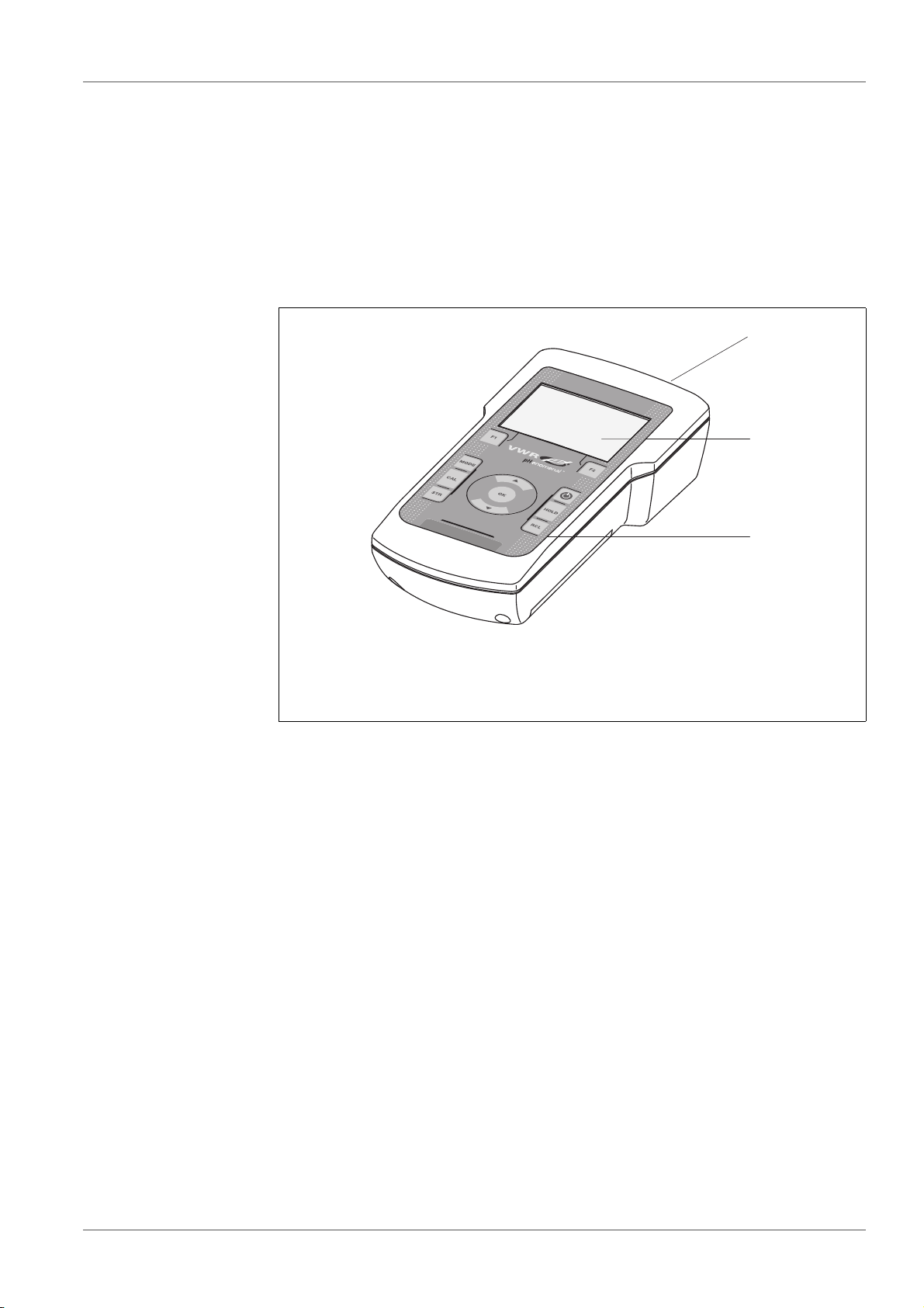
2 Overview
2.1 MU 6100 H meter
The MU 6100 H meter enables you to perform measurements (pH, U, conductivity, dissolved oxygen) ) quickly and reliably.
The MU 6100 H provides the maximum degree of operating comfort, reliability
and measuring certainty for all applications.
1 Keypad
2 Display
3 Connectors
2.2 Sensors
A measuring system ready to measure consists of the MU 6100 H meter and a
suitable sensor.
Suitable sensors are pH electrodes, ORP electrodes, D.O. sensors and
conductivity measuring cells.
ba77077e02 09/2014 9
Technical data MU 6100 H
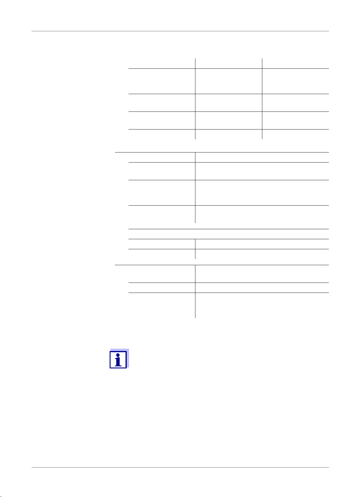
3 Technical data
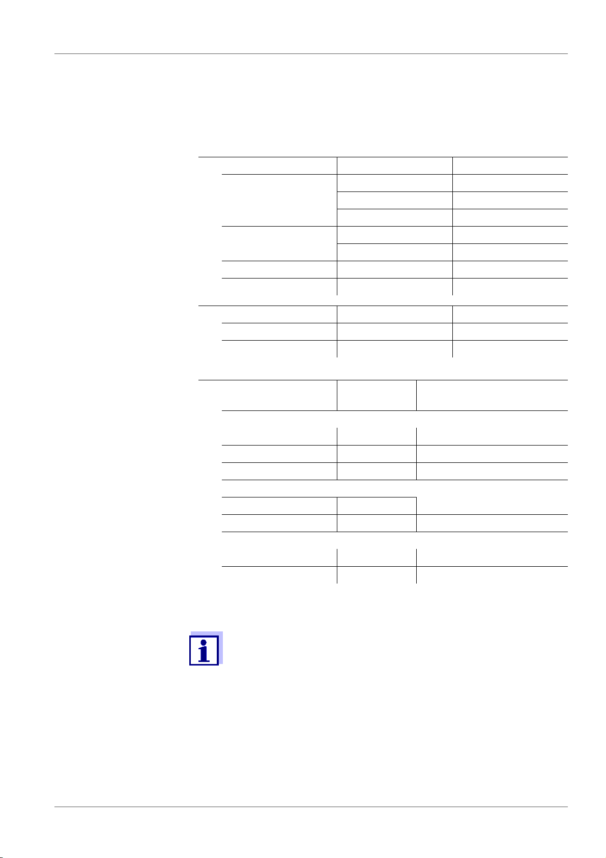
3.1 Measuring ranges, resolution, accuracy
3.1.1 pH/ORP
Measuring ranges,
resolution
Variable Measuring range Resolution
pH -2.0 ... +20.0 0.1
-2.00 ... +20.00 0.01
- 2.000 ... + 19.999 0.001
U [mV] -2500 ... +2500 1
-1200.0 ... +1200. 0.1
T [°C] -5.0 ... +105.0 0.1
T [°F] 23.0 ... +221.0 0.1
Manual
temperature input
Variable Range Increment
T
T
[°C] -25 ... +130 1
manual
[°F] -13 ... +266 1
manual
Accuracy (± 1 digit) Variable Accuracy Temperature of the test
sample
pH / range *
-2.0 ... +20.0 ± 0.1 +15 °C ... +35 °C
-2.00 ... +20.00 ± 0.01 +15 °C ... +35 °C
- 2.000 ... + 19.999 ± 0.005 +15 °C ... +35 °C
U [mV] / range
-2500 ... +2500 ± 1 +15 °C ... +35 °C
-1200.0 ... +1200. ± 0.3 +15 °C ... +35 °C
T [°C] / temperature sensor
NTC 30 ± 0.1
PT 1000 ± 0.1
* when measuring in a range of ± 2 pH around a calibration point
The accuracy values specified here apply exclusively to the meter.
The accuracy of the electrodes and buffer solutions has to be taken
into account additionally.
10 ba77077e02 09/2014
MU 6100 H Technical data
3.1.2 Oxi
Measuring ranges,
resolution
(depending on the
sensor)
Variable Measuring range Resolution
Concentration [mg/l] 0 ... 20.00 (0 ... 20.0)
20.0 ... 90.0
(20 ... 90)
Saturation [%] 0 ... 200.0 (0 ... 600)
0 ... 600
D.O. partial pressure
[mbar]
0 ... 200.0 (0 ... 1250)
0 ... 1250
T [°C] 0 ... 50,0 0.1
Accuracy (± 1 digit) Variable Accuracy
Concentration [mg/l] ± 0.5 % of measured value
at ambient temperature of +5 °C ... +30 °C
Saturation [%] ± 0.5% of measured value
when measuring in the range of ± 10 K
around the calibration temperature
D.O. partial pressure
[mbar]
± 0.5 % of measured value
at ambient temperature of +5 °C ... +30 °C
T [°C] / temperature sensor
0.01 (0.1)
0.1 (1)
0.1 (1)
1
0.1 (1)
1
NTC 30 ± 0.1
PT 1000 ± 0.1
Correction functions Temperature
compensation
Salinity correction 0 ... 70.0 SAL
Air pressure correction
The accuracy values specified here apply exclusively to the meter.
The accuracy of the D.O. sensors has also to be taken into
account.
Accuracy better than 2 % at 0 ... +40 °C
Automatic through integrated
pressure sensor in the range of 500 ... 1100
mbar
ba77077e02 09/2014 11

Technical data MU 6100 H
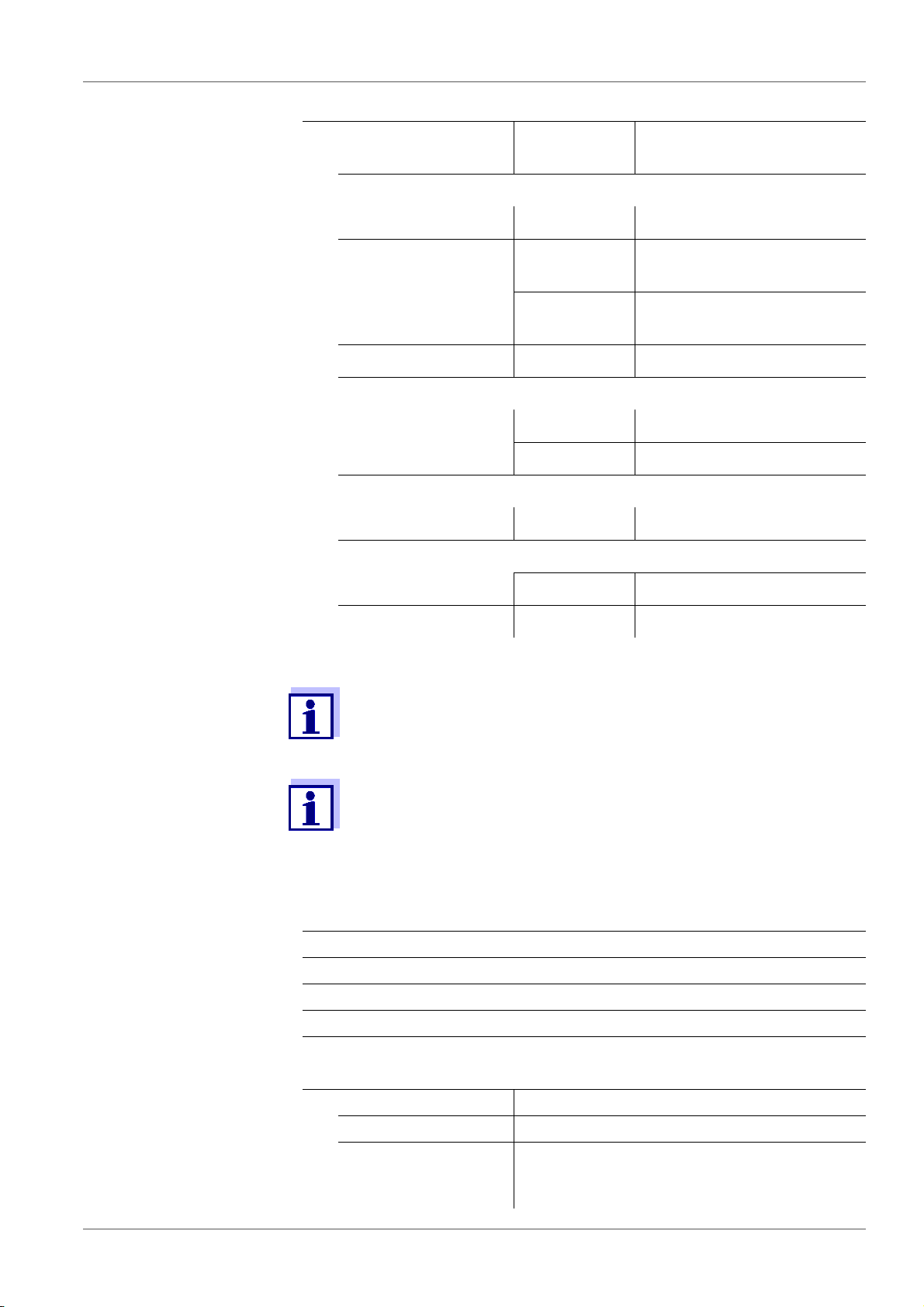
3.1.3 Cond
Measuring ranges,
resolution
(depending on the sensor)
Variable Measuring range Resolution
ϰ[µS/cm] 0.000 ... 1.999*
0.00 ... 19.99**
0.0 ... 199.9
200 ... 1999
ϰ [mS/cm] 2.00 ... 19.99
20.0 ... 199.9
200 ... 1000
(Resistivity)
ρ
[Ohm*cm]
(Resistivity)
ρ
[kOhm*cm]
(Resistivity)
ρ
[MOhm*cm]
SAL 0.0 ... 70.0
1.000 ... 1.999
2.00 ... 19.99
20.0 ... 199.9
200 ... 1999
2.00 ... 19.99
20.0 ... 199.9
200 ... 1999
2.00 ... 19.99**
20.0 ... 199.9*
0.001
0.01
0.1
1
0.01
0.1
1
0.001
0.01
0.1
1
0.01
0.1
1
0.01
0.1
0.1
according to the IOT
table
TDS 0 ... 1999 mg/l
2.00 ... 19.99 g/l
20.0 ... 199.9 g/l
T [°C] -5.0 ... +105.0 0.1
T [°F] +23.0 ... +221.0 0.1
* only possible with cells of the cell constant, 0.010 cm-1
** only possible with cells of the cell constant, 0.010 cm
0.110 cm
-1
Cell constants Cell constant C Values
Can be calibrated in
the ranges
0.450 ... 0.500 cm
0.800 ... 0.880 cm
Adjustable 0.090 ... 0.110 cm
0.010 cm-1 (fixed)
0,250 ... 1,000 cm
Reference temperature Reference tempera-
Values
ture
1
0.01
0.1
-1
or 0.090 ...
-1
-1
-1
-1
Adjustable 20 °C (Tref20)
25 °C (Tref25)
12 ba77077e02 09/2014
MU 6100 H Technical data
Accuracy (± 1 digit) Variable Accuracy Temperature of the test
sample
ϰ and ρ / temperature compensation
None (Off) ± 0.5 %
Nonlinear (nLF) ± 0.5 % 0 °C ... +35 °C
according to EN 27 888
± 0.5 % +35 °C ... +50 °C
enhanced nLF function
Linear (lin) ± 0.5 % +10 °C ... +75 °C
SAL / range
0.0 ... 42.0 ± 0.1 +5 °C ... +25 °C
± 0.2 +25 °C ... +30 °C
TDS [mg/l]
± 0.5 %
T [°C] / temperature sensor
NTC 30 ± 0.1
PT 1000 ± 0.1
The accuracy values specified here apply exclusively to the meter.
The accuracy of the measuring cell has also to be taken into
account.
Further data are given in the documentation of your sensor.
3.2 General data
Dimensions ca. 180 x 80 x 55 mm
Weight Approx. 0.4 kg
Mechanical structure Type of protection IP 67
Electrical safety Protective class III
Test certificates CE
Ambient
conditions
Storage -25 °C ... +65 °C
Operation +5 °C ... +55 °C
Admissible relative
humidity
Yearly mean: < 75 %
30 days/year: 95 %
Other days: 85 %
ba77077e02 09/2014 13

Technical data MU 6100 H
Power
supply
Batteries 4 x 1.5 V alkali-manganese batteries, type
AA
Rechargeable batteries
4 x 1.2 V NiMH rechargeable batteries,
type AA
(no charging function)
Operational life Up to 1000 h without / 150 h with illumination
pH sensor input Input resistance > 5 * 10
Input current < 1 * 10
USB interface Type USB 1.1
USB B (device), data output
Baud rate Adjustable:
1200, 2400, 4800, 9600, 19200 Baud
Data bits 8
Stop bits 2
Parity None
Handshake RTS/CTS
Cable length Max. 3 m
12
-12
ohm
A
Guidelines
and norms used
EMC EC directive 2004/108/EC
EN 61326-1
EN 61000-3-2
EN 61000-3-3
FCC Class A
Meter safety EC directive 2006/95/EC
EN 61010-1
UL 61010-1
CAN/CSA-C22.2#61010-1
IP protection class EN 60529
14 ba77077e02 09/2014

MU 6100 H Commissioning
4 Commissioning
4.1 Scope of delivery
MeterMU 6100 H
4 batteries 1.5 V Mignon type AA
Short instructions
CD-ROM with
– USB drivers
– detailed operating manual
– Software MultiLab Importer
4.2 Power supply
The MU 6100 H is supplied with power in the following ways:
Battery operation (4 x alkaline manganese batteries, type AA)
USB operation via a connected USB-B cable
4.3 Initial commissioning
Perform the following activities:
Insert the supplied batteries
Switch on the meter
(see section 5.2 S
Set the date and time
(see section 5.4.6 E
page 24)
WITCHING ON THE METER, page 19)
XAMPLE 2 ON NAVIGATION: SETTING THE DATE AND TIME,
ba77077e02 09/2014 15

Commissioning MU 6100 H
1
2
4.3.1 Inserting the batteries
1Screws
2 Battery compartment
CAUTION
Make sure that the poles of the batteries are positioned correctly.
The ± signs on the batteries must correspond to the
the battery compartment.
You can operate the meter either with normal batteries or with
rechargeable batteries (Ni-MH). In order to charge the batteries, an
external charging device is required.
1. Place four batteries (type Mignon AA) in the battery compartment.
2. Close the battery compartment.
3. Set the date and time
(see section 5.4.6 E
XAMPLE 2 ON NAVIGATION: SETTING THE DATE AND TIME,
page 24).
± signs in
16 ba77077e02 09/2014

MU 6100 H Operation
5Operation
5.1 General operating principles
5.1.1 Keypad
In this operating manual, keys are indicated by brackets <..> .
The key symbol (e.g. <OK>) generally indicates a short keystroke (under
2 sec) in this operating manual. A long keystroke (approx. 2 sec) is indicated
by the underscore behind the key symbol (e.g. <OK
_>).
<F1>:
<F1
_>:
<F2>:
<F2
_>:
<On/Off>: Switches the meter on or off
<MODE>: Selects the measured parameter / Quits the settings
<CAL>:
_>:
<CAL
<STR>:
_>:
<STR
<RCL>:
_>:
<RCL
<><>:
<_><_>:
<OK>:
_>:
<OK
Softkeys providing situation dependent functions, e.g.:
<F2>/[USB output]:
Outputs data to the USB interface
<F2_>/[USB output]:
Configures the automatic data output to the USB inter-
face
Calls up the calibration procedure
Displays the calibration data
Saves a measured value manually
Opens the menu for the automatic save function
Displays the manually stored measured values
Displays the automatically stored measured values
Menu control, navigation
Increments, decrements values
Increments, decrements values continuously
Opens the menu for measurement settings / confirms
entries
Opens the menu for system settings
<HOLD> Freezes the measured value (HOLD function)
ba77077e02 09/2014 17
Operation MU 6100 H
HOLD AR
25.0
6.093
pH
°C
4
3
2
5
6
7
8
1
AutoCal TEC
15.03.2014
08:00
Menu
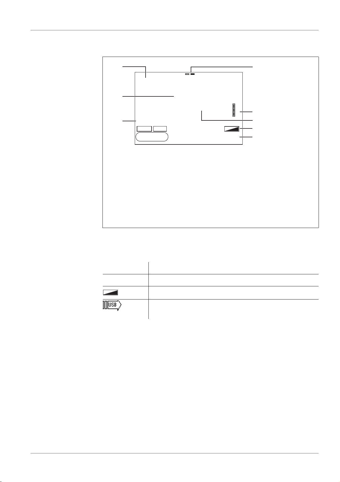
5.1.2 Display
1 Status information (sensor)
2 Measured value (with unit)
3 Measured parameter
4 Channel display: Plug position of the sensor
5 Sensor symbol (calibration evaluation, calibration interval)
6 Measured temperature (with unit)
7 Status information (meter)
8 Softkeys and date + time
5.1.3 Status information (meter)
AR Stability control (AutoRead) is active (calibration)
HOLD Measured value is frozen (<HOLD> key)
Batteries are almost empty
Data are automatically output to the USB-B interface at
intervals
18 ba77077e02 09/2014
MU 6100 H Operation
1
2
3
4
5
pH
6.949
25.0
°C
15.02.2014
14:15
Menu
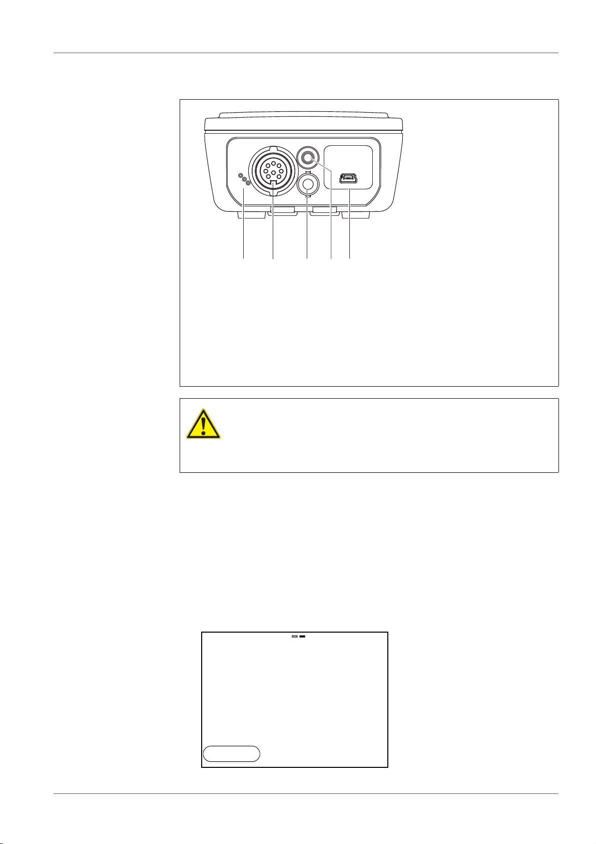
5.1.4 Connectors
1 pH electrode
2 Temperature sensor
3 D.O. sensor or conductivity measuring cell
4 Mini USB-B interface
5 Service interface
CAUTION
Only connect sensors to the meter that cannot return any voltages or currents that are not allowed (> SELV and > current
circuit with current limiting).
Almost all customary sensors fulfill these conditions.
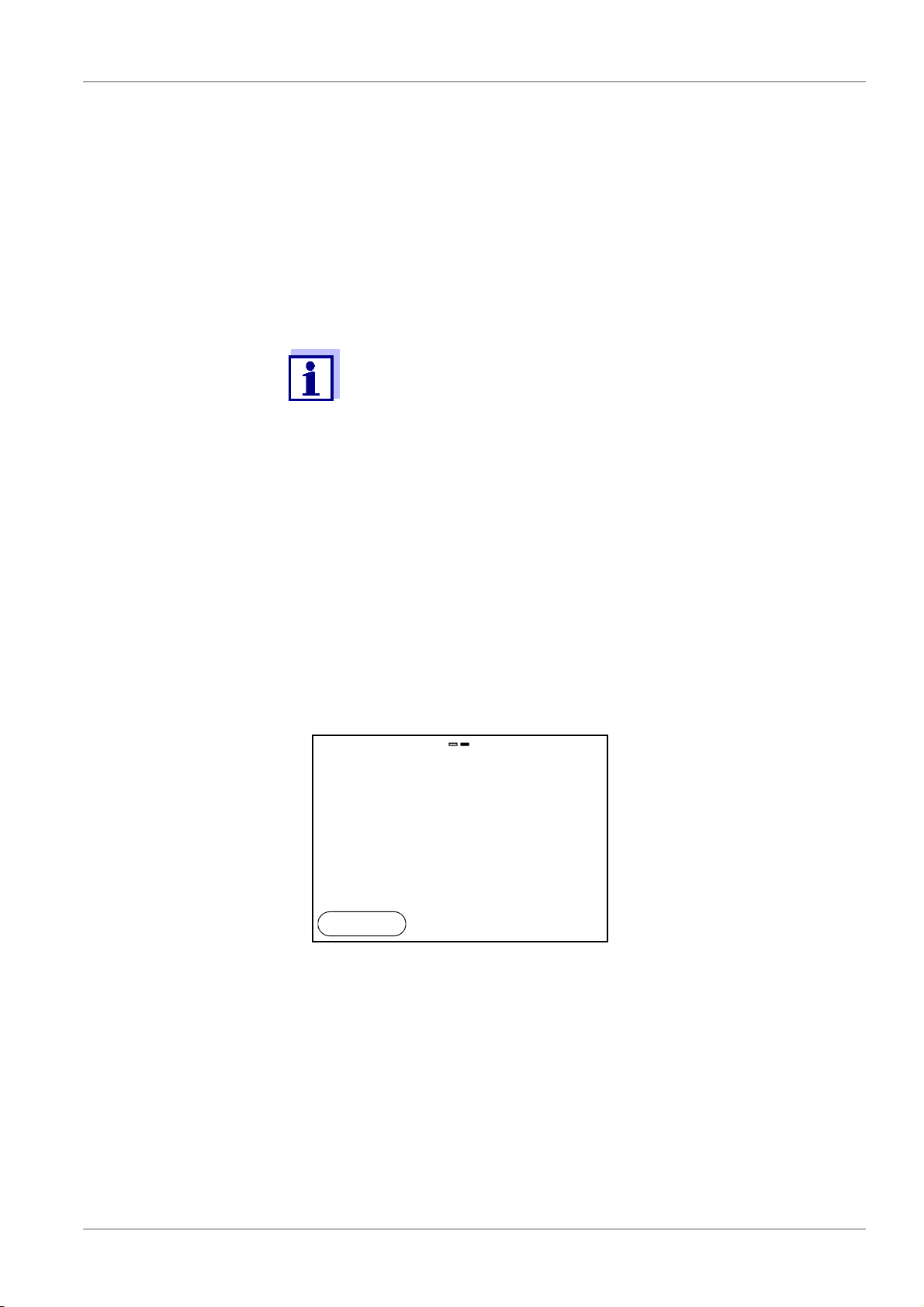
5.2 Switching on the meter
1. Switch the meter on with <On/Off>.
The meter performs a self-test.
The display shows the manufacturer's logo while the self-test is being
performed.
The measured value display appears.
ba77077e02 09/2014 19

Operation MU 6100 H
5.3 Switching off
1. Switch the printer off with <On/Off>.
Automatic shut-off
function
The instrument has an automatic shut-off function in order to save the batteries
(see section 10.2.1 S
YSTEM, page 62). The automatic shut-off function switches
off the meter if no key is pressed for an adjustable period.
The automatic shut-off function is not active
if the communication cable is connected
if the Automatic data storage function is active, or with automatic data trans-
mission
Display illumination The meter automatically switches off the display illumination if no key is
pressed for 30 seconds. The illumination is switched on with the next keystroke
again.
You can also generally switch the display illumination on or off (see section
10.2.1 S
YSTEM, page 62).
5.4 Navigation
The principles of navigation in menus and dialogs are explained in the following
sections.
5.4.1 Operating modes
The instrument has the following operating modes:
Operating
Explanation
mode
Measuring The measurement data of the connected sensor are shown
in the measured value display
Calibration The course of a calibration with calibration information, func-
tions and settings is displayed
Storing in
The meter stores measuring data automatically or manually
memory
Transmitting data
The meter transmits measuring data and calibration records
to a USB-B interface automatically or manually.
Setting The system menu or a sensor menu with submenus, set-
tings and functions is displayed
Only those displays and functions are available in the active operating mode
that are currently being required.
20 ba77077e02 09/2014

MU 6100 H Operation
General
Interface
Clock
Service information
Reset
System
15.02.2014
14:15
Back
5.4.2 Measured value display
In the measured value display, open the setting menus with <OK>. The current
functions of the softkeys are shown on the display.
Use <OK> (short
pressure) to open the menu for calibration and measure-
ment settings for the displayed measured parameter.
Use <OK
_> (long keystroke (approx. 2 s) to open the Storage & config
menu with the sensor-independent settings.
Use the keys of the keypad to carry out further functions such as storage or calibration (see section 5.1.1 K
EYPAD, page 17). These functions are not available
in other operating situations.
5.4.3 Menus and dialogs
The menus for settings and dialogs in procedures contain further subelements.
To select a subelement, use the <><> keys. The current selection is dis-
played with a frame.
To make further settings, switch to the next higher menu level with
<F1>[Back].
Use <MODE> to return to the measured value display.
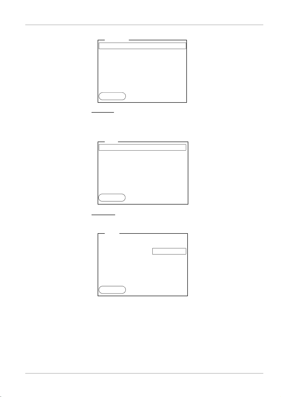
5.4.4 Elements in menus and dialogs
Submenus
The name of the submenu is displayed at the upper edge of the frame. Submenus are opened by confirming with <OK>. Example:
Settings
Settings are indicated by a colon. The current setting is displayed on the
right-hand side. The setting mode is opened with <OK>. Subsequently, the
setting can be changed with <><> and <OK>. Example:
ba77077e02 09/2014 21
Operation MU 6100 H
Language: Deutsch
Beep: Off
Illumination: On
Contrast: 50 %
Switchoff time: 1 h
Temperature unit: °C
Stability control: On
General
15.02.2014
14:15
Back
Calibration record
Calibration data storage
Buffer: TEC
One point calibration: Yes
Calibration interval: 7 d
Unit for slope: mV/pH
i
4.00 7.00 10.00 (20 °C)
pH
15.02.2014
14:15
Back
Calibration record
Calibration data storage
Buffer: TEC
One point calibration: Yes
Calibration interval: 7 d
Unit for slope: mV/pH
i
4.00 7.00 10.00 (20 °C)
pH
15.02.2014
14:15
Back
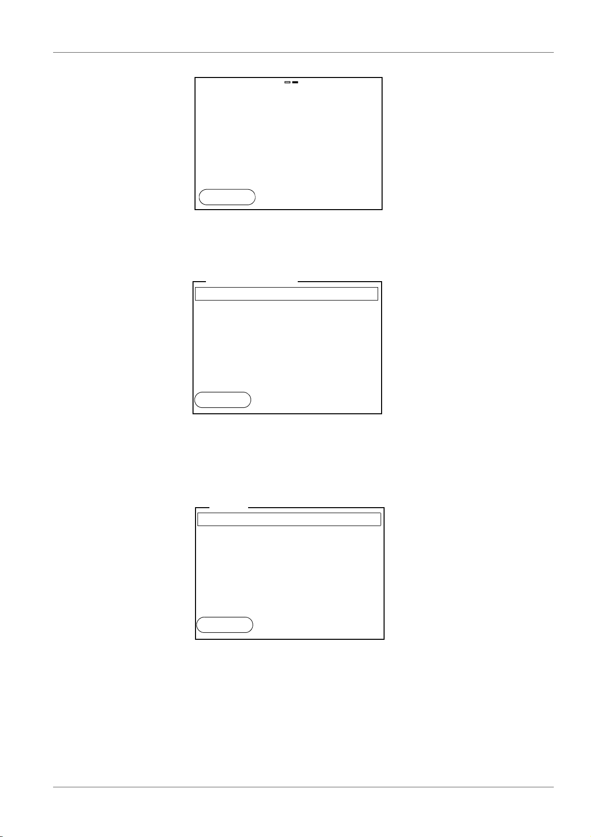
Functions
Functions are designated by the name of the function. They are immediately
carried out by confirming with <OK>.
Example: Display the Calibration record function.
22 ba77077e02 09/2014
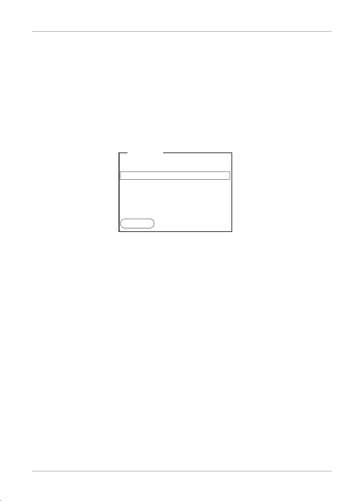
Messages
Information is marked by the i symbol. It cannot be selected. Example:
5.4.5 Navigation example 1:Setting the language
1. Press the <On/Off> key.
The measured value display appears.
The instrument is in the measuring mode.
MU 6100 H Operation
pH
6.949
25.0
°C
15.02.2014
14:15
Menu
System
Data storage
Storage & config
15.02.2014
14:15
Back
General
Interface
Clock
Service information
Reset
System
15.02.2014
14:15
Back
2. Open the Storage & config menu with <OK_>.
The instrument is in the setting mode.
3. Select the System submenu with <><>.
The current selection is displayed with a frame.
4. Open the System submenu with <OK>.
5. Select the General submenu with <><>.
The current selection is displayed with a frame.
6. Open the General
submenu with <OK>.
ba77077e02 09/2014 23

Operation MU 6100 H
Language: Deutsch
Beep: Off
Illumination: On
Contrast: 50 %
Switchoff time: 1 h
Temperature unit: °C
Stability control: On
General
15.02.2014
14:15
Back
Language: Deutsch
Beep: Off
Illumination: On
Contrast: 50 %
Switchoff time: 1 h
Temperature unit: °C
Stability control: On
General
15.02.2014
14:15
Back
7. Open the setting mode for the Language with <OK>.
24 ba77077e02 09/2014
8. Select the required language with <><>.
9. Confirm the setting with <OK>.
The meter switches to the measuring mode.
The selected language is active.
5.4.6 Example 2 on navigation: Setting the date and time
The meter has a clock with a date function. The date and time are shown in the
measured value display.
When storing measured values and calibrating, the current date and time are
automatically stored as well.
The correct setting of the date and time and date format is important for the following functions and displays:
Current date and time
Calibration date
Identification of stored measured values.
Therefore, check the time at regular intervals.
After a fall of the supply voltage (empty batteries), the date and time
are reset.
MU 6100 H Operation
Date format: dd.mm.yyyy
Date: 15.02.2014
Time: 14:15:25
Clock
15.02.2014
14:15
Back
The date format can be switched from the display of day, month, year
(dd.mm.yyyy) to the display of month, day, year (mm/dd/yyyy or mm.dd.yyyy).
1. In the measured value display:
Open the Storage & config menu with <OK
_>.
The instrument is in the setting mode.
2. Select and confirm the System / Clock menu with <><> and <OK>.
The setting menu for the date and time opens up.
3. Select and confirm the Time menu with <><> and <OK>.
The hours are highlighted.
4. Change and confirm the setting with <><> and <OK>.
The minutes are highlighted.
5. Change and confirm the setting with <><> and <OK>.
The seconds are highlighted.
6. Change and confirm the setting with <><> and <OK>.
The time is set.
7. If necessary, set the Date and Date format. The setting is made similarly
to that of the time.
8. To make further settings, switch to the next higher menu level with
[Back]<F1>.
or
Switch to the measured value display with <MODE>.
The instrument is in the measuring mode.
ba77077e02 09/2014 25
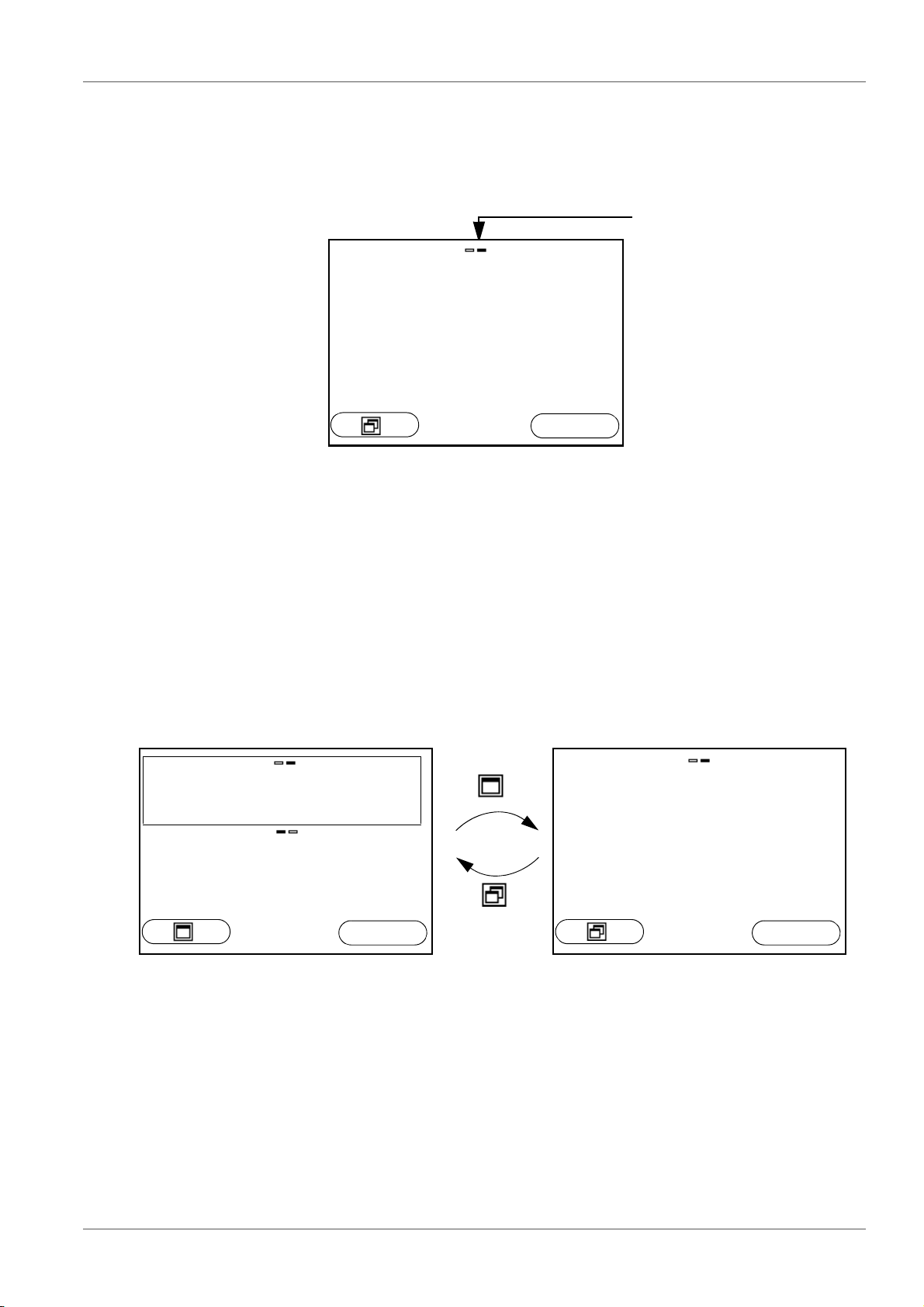
Operation MU 6100 H
Channel display
Display of the plug position
for the respective parameter
The filled bar indicates for
each connected sensor to
which plug position of the
meter it is connected.
pH
6.949
24.8 °C
15.02.2014
14:15
USB output
pH 6.966
25.0 °C
ϰ
0.840 1/cm
25.0 °C
15.02.2014
14:15
USB output
pH
6.966
25.0
°C
15.02.2014
14:15
USB output
5.5 Channel display
The MU 6100 H manages the connected sensors and displays which sensor is
plugged to which connection.
5.5.1 Display of several sensors in the measuring mode
The measured values of the connected sensors can be displayed in the following ways:
Clear display of all connected sensors
Detailed display of one sensor
With the softkey you can very easily switch between the two display types. The
suitable softkey is displayed depending on the operating situation.
26 ba77077e02 09/2014
MU 6100 H pH value
pH
6.949
24.8 °C
15.02.2014
14:15
Menu
6 pH value
6.1 Measuring
6.1.1 Measuring the pH value
NOTE
When connecting an grounded PC/printer, measurements cannot be
performed in grounded media as the values would be incorrect.
The USB interface is not galvanically isolated.
To ensure the high measurement accuracy of the measuring system, always measure with a calibrated electrode (see section 6.2
C
ALIBRATION, page 29).
1. Connect the pH electrode to the meter.
2. If necessary, select the measured parameter with <MODE>.
3. When measuring without temperature sensor:
– Temper the test sample, or measure the current temperature.
– Enter the temperature value in the menu.
4. Immerse the pH electrode in the test sample.
The measured value is checked for stability (automatic stability control).
The display of the measured parameter flashes.
5. Wait for a stable measured value.
The display of the measured parameter no longer flashes.
Stability control
(AutoRead )
Criteria for a stable
measured value
The stability control function (AutoRead) continually checks the stability of the
measurement signal. The stability has a considerable impact on the reproducibility of measured values (see section 10.2.3 A
page 63).
The Stability control function checks whether the measured values are stable
UTOMATIC STABILITY CONTROL,
ba77077e02 09/2014 27
pH value MU 6100 H
within the monitored time interval.
Freezes the mea-
sured value (HOLD
function)
Measured
Time interval Stability in the time interval
parameter
pH value 15 seconds
Temperature 15 seconds
Δ : better than 0.01 pH
Δ : better than 0.5 °C
The minimum duration until a measured value is assessed as stable is the
monitored time interval. The actual duration is mostly longer.
With the HOLD function, you can freeze the current measured value. The displayed measured value stops changing until you switch the HOLD function off.
1. Freeze the measured value with <HOLD>.
The [HOLD] status indicator is displayed.
2. Release the frozen measured value again with <HOLD>.
The HOLD function is switched off.
The [HOLD] status display disappears.
6.1.2 Measuring the temperature
For reproducible pH measurements, it is essential to measure the temperature
of the test sample.
You have the following options to measure the temperature:
Automatic measurement of the temperature with the temperature sensor
(NTC30 or Pt1000) integrated in the sensor.
Measurement by an external temperature sensor.
Manual determination and input of the temperature.
The measuring instrument recognizes whether a suitable sensor is connected
and automatically switches on the temperature measurement.
The display of the temperature indicates the active temperature measuring
mode:
Tempera-
ture sensor
Resolution of the
temp. display
Temp. measurement
yes 0.1 °C Automatic with temperature sensor
- 1 °C Manual
If you wish to measure (or calibrate) without temperature sensor, proceed as
follows:
1. Measure the current temperature of the test sample.
2. In the <OK>/pH/Man. temperature menu, set the temperature value with
<><>.
28 ba77077e02 09/2014

MU 6100 H pH value
6.2 Calibration
6.2.1 Why calibrate?
pH electrodes age. This changes the zero point (asymmetry) and slope of the
pH electrode. As a result, an inexact measured value is displayed. Calibration
determines and stores the current values of the zero point and slope of the
electrode.
Thus, you should calibrate at regular intervals.
6.2.2 When do you have to calibrate?
After connecting a sensor
Routinely within the framework of the company quality assurance
When the calibration interval has expired
6.2.3 Automatic calibration (AutoCal)
Make sure that in the sensor menu, Buffer menu, the buffer set is correctly
selected (see 10.1.1 S
ETTINGS FOR PH MEASUREMENTS, PAGE 52).
Use any one to five buffer solutions of the selected buffer set in ascending or
descending order.
Below, calibration with Technical buffers (TEC) is described. When other buffer
sets are used, other nominal buffer values are displayed. Apart from that, the
procedure is identical.
If single-point calibration was set in the menu, the calibration procedure is automatically finished with the measurement of buffer solution 1 and the calibration record is displayed.
1. Connect the pH electrode to the meter.
2. When measuring without temperature sensor:
– Temper the buffer solution, or measure the current temperature.
– Enter the temperature value in the menu.
3. In the measured value display, select the measured parameter pH or mV
with <MODE>.
4. Start the calibration with <CAL>.
The calibration display for the first buffer appears (voltage display).
ba77077e02 09/2014 29
 Loading...