

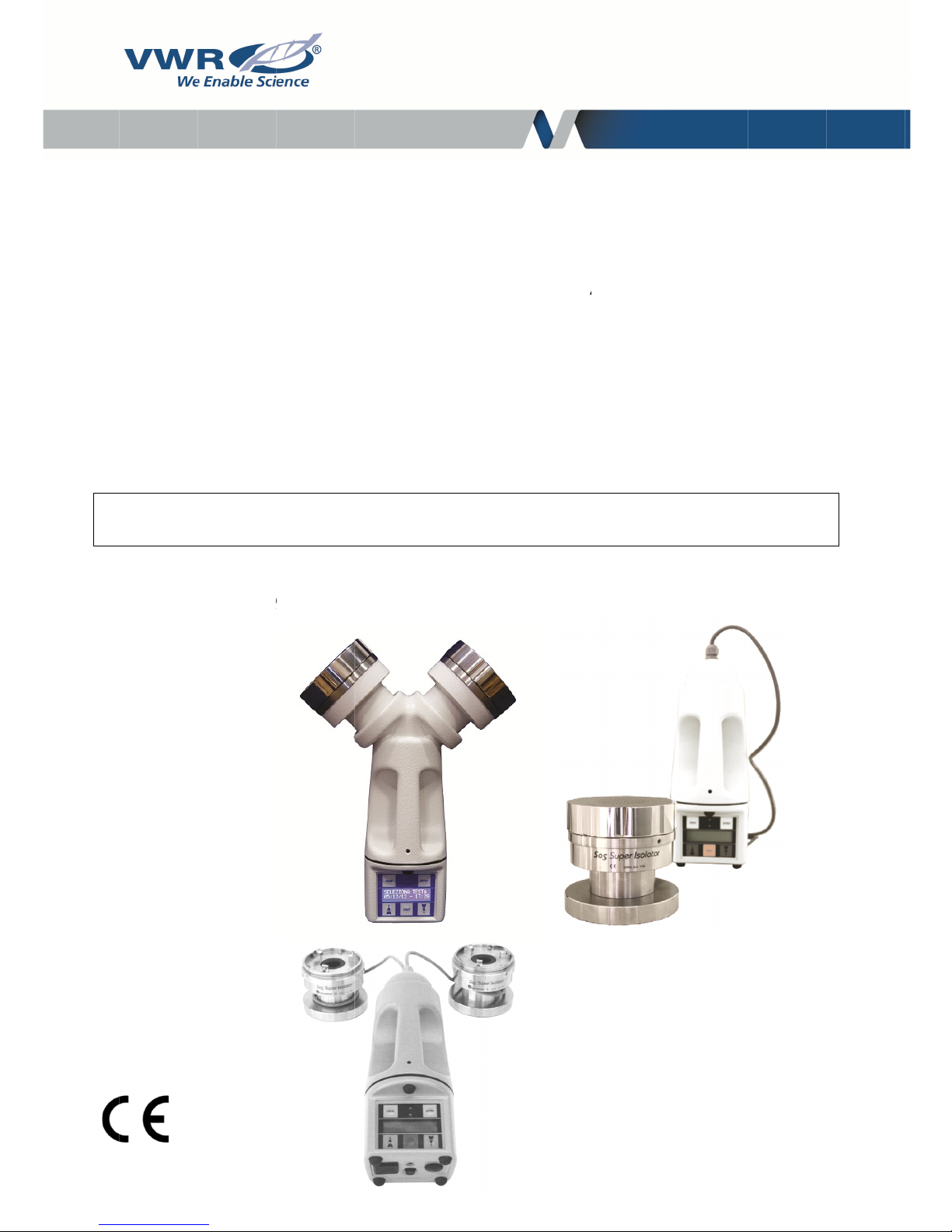
VWR International ISOLATOR 180 Petri, ISOLATOR 100 Contact, ISOLATOR 180 Contact, ISOLATOR 100 Petri, DUO SAS 360 Petri Instruction Manual
...
E
u
71
71
71
71
71
71
71
71
ropea
n
0-0867
0-0866
0-0943
0-0944
0-0945
0-0946
0-0977
0-0978
V
W
R
catalo
g
®
M
S
A
INS
T
ue nu
m
icro
b
S
A
SAS
S
S Su
p
RUC
T
bers:
iolo
g
S Sup
uper I
er DU
O
ION
M
ical
A
r DU
O
SOLA
T
ISO
L
AN
U
V
I
ir
S
OR
ATO
R
AL
ersion:
ssued:
J
amp
l
1.2
uly 201
6
er

2
Legal address of manufacturer
Europe
VWR International Srl
Via S. Giusto 85
20153 Milano
Italy
Tel.: + 39 02-3320311
http://be.vwr.com
Country of origin: Italy

3
Table of contents
Warning ........................................................................................................................................ 5
Safety information ....................................................................................................................... 5
Unit descriptions ......................................................................................................................... 6
Technical features ....................................................................................................................... 7
Intended use ................................................................................................................................ 7
Principle ........................................................................................................................................... 7
The basic idea.................................................................................................................................. 8
Brief instructions ........................................................................................................................ 8
Brief instructions for SAS Isolator .................................................................................................... 8
Brief operating instructions for DUO SAS Super 360 - DUO SAS Isolator ..................................... 8
Practical use of contact plates ......................................................................................................... 9
List of menus and utility sub menus ................................................................................................ 9
Preliminary inspection .................................................................................................................... 10
Holder adjustment .......................................................................................................................... 10
Petri head adapter (optional) ......................................................................................................... 10
90 mm Petri dish filling ................................................................................................................... 10
Tripod installation (optional) ........................................................................................................... 10
Functions ................................................................................................................................... 10
Operations ..................................................................................................................................... 10
Start with the same air volume as the previous sample ................................................................ 11
‘STANDARD MODE’ ...................................................................................................................... 11
‘USER MODE’ ................................................................................................................................ 12
‘PROGRAM MODE’ ....................................................................................................................... 12
‘DELAY MODE’ .............................................................................................................................. 13
‘MULTIMODE’ ................................................................................................................................ 14
intervals). ...................................................................................................................................... 14
UTILITY MODE’ .......................................................................................................................... 15
‘SET TIME’ ..................................................................................................................................... 16

4
‘MODE’ ........................................................................................................................................... 16
‘SET AUTOSWITCH’ ..................................................................................................................... 16
‘PRINT’ ........................................................................................................................................... 17
‘DISPLAY RECORD’ ..................................................................................................................... 17
‘CLEAR RECORD’ ......................................................................................................................... 18
‘LANGUAGE’ ................................................................................................................................. 18
‘IDENTIFY’ ..................................................................................................................................... 18
‘SAMPLING SITE’ .......................................................................................................................... 18
‘CALIBRATION DUE’ (optional) ..................................................................................................... 19
List of system messages ............................................................................................................... 19
Accessories ............................................................................................................................... 20
Troubleshooting ........................................................................................................................ 21
Technical service ...................................................................................................................... 22
Warranty ..................................................................................................................................... 22
Compliance with local laws and regulations .......................................................................... 22
Equipment disposal .................................................................................................................. 23

5
Warning
This document is the property of VWR International S.r.l. - Milan - Italy
It may not be duplicated or distributed without the owner’s authorisation.
Patent Pending
Manufactured by VWR International S.r.l. - Milan, Italy
Safety information
Use the device just for the indicated purposes.
The device must be correctly used according to this instruction manual, before starting any operation.
Immediately replace any electrical cable when damaged.
Always disconnect the charger before:
Repairing or maintenance; these operations must be carried out by qualified staff
Keep the unit clean
Use original spare parts and accessories for any replacement.
Do not use this device in the presence of explosive gas.
Please follow the guidelines below and read this manual in its entirety to ensure safe operation of the unit.
Be aware that the voltage and frequency of the electrical system are compatible with the electrical requirements of
the battery charger.
Never use a non OEM charger to charge the air sampler.
Use of improper charger may damage the unit.
ENGLISH
6
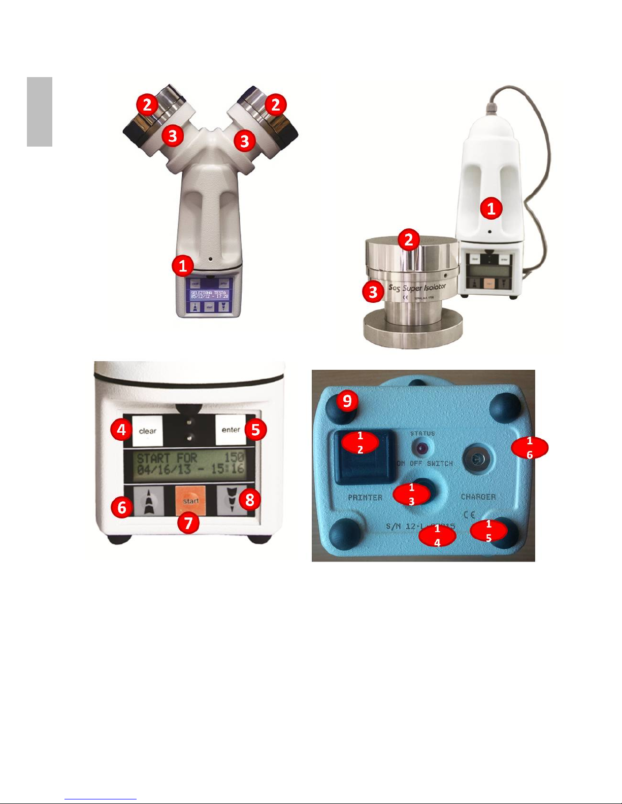
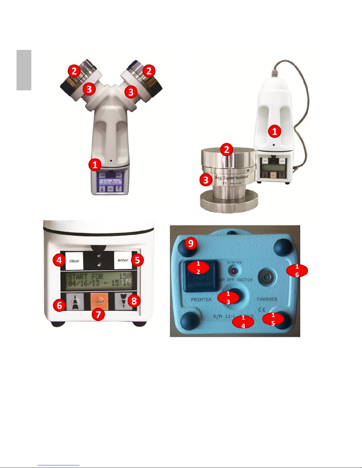
Unit descriptions
1. Command unit
2. Stainless steel head
3. Motor housing
4. “Clear” button
5. “Enter” button
6. Arrow “Up”
7. “Start” button
8. Arrow “Down”
9. Standing feet
10. Printer connection (not used)
11. Main switch
12. Serial number
13. CE mark
14. Charger connection
ENGLISH
7
Technical features
Model DUO SAS 360
Contact
DUO SAS 360
Petri
DUO SAS
ISOLATOR Contact
DUO SAS
ISOLATOR Petri
Cat. No. 710-0867 710-0866 710-0977 710-0978
Airflow 180 l/min 180 l/min 180 l/min 180 l/min
Used with 55 mm contact
plates
90 mm Petri dishes 55 mm contact
plates
90 mm Petri dishes
Portable Yes Yes Yes Yes
Battery Rechargeable Rechargeable Rechargeable Rechargeable
Battery life 40 000 l 40 000 l 40 000 l 40 000 l
Model ISOLATOR 100
Contact
ISOLATOR 180
Contact
ISOLATOR 100
Petri
ISOLATOR 180
Petri
Cat. No. 710-0943 710-0944 710-0945 710-0946
Airflow 100 l/min 180 l/min 100 l/min 180 l/min
Used with 55 mm contact
plates
55 mm contact
plates
90 mm Petri dishes 90 mm Petri dishes
Portable Yes Yes Yes Yes
Battery Rechargeable Rechargeable Rechargeable Rechargeable
Battery life 70 000 l 40 000 l 70 000 l 40 000 l
Intended use
Principle
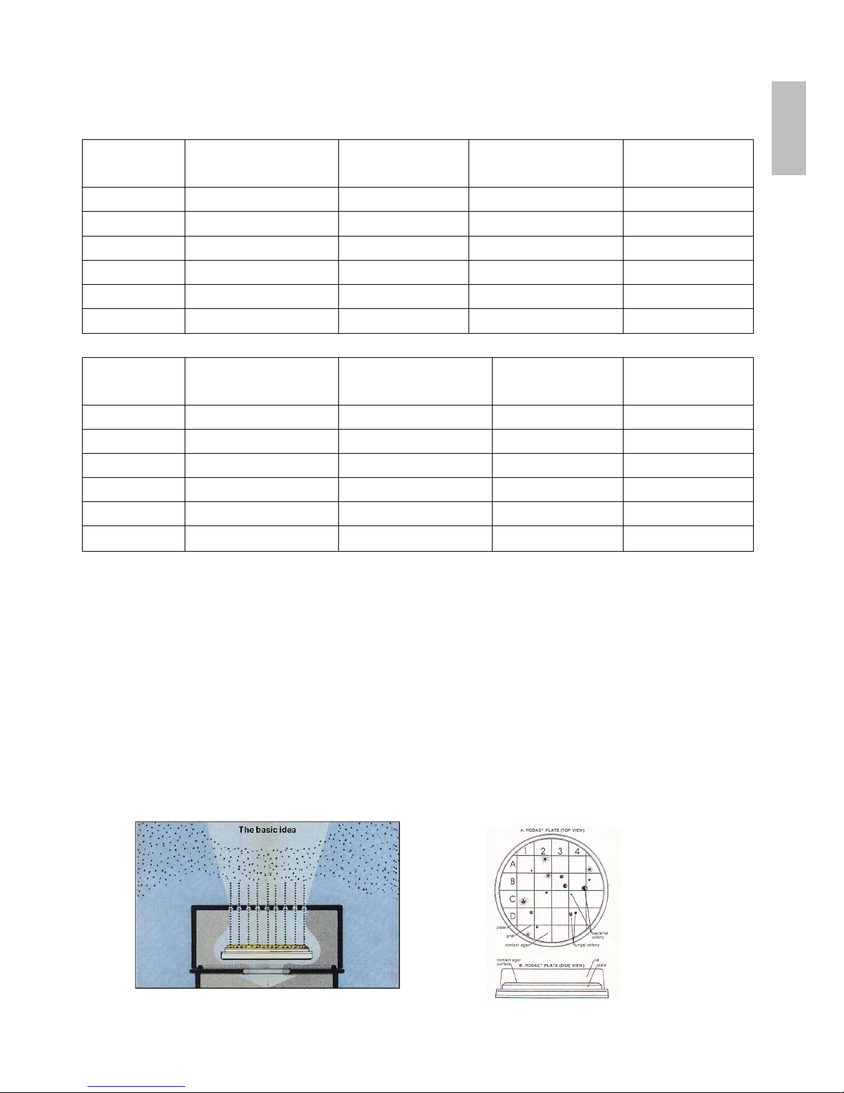
The Surface Air System (SAS) encompasses several models which use the same principle. Air is aspirated at a
fixed speed for variable time through a head which has been machined with a series of small holes of a special
design. The resulting laminar airflow is directed onto the agar surface of a “RODAC Plate” (or a Petri dish)
containing medium for microbiological analysis.
When the selected sampling cycle is completed, the plate is removed and incubated. The organisms are then visible
to the naked eye and can be counted for the assessment of contamination levels.
ENGLISH

8
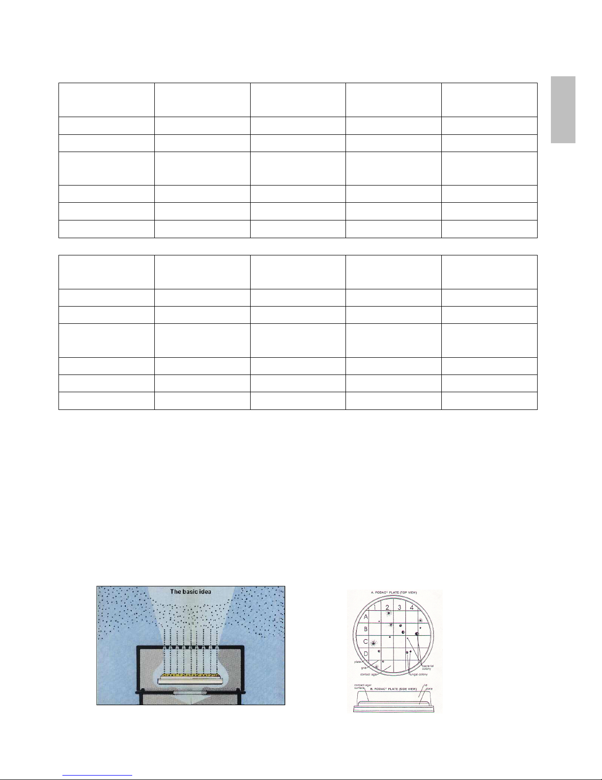
The basic idea
The key features of the Surface Air System (SAS) are:
1. To use a simple and inexpensive “contact plate” (“SURFAIR PLATE”, “RODAC”) for surface, hands or air
control. These plates are very well known and easily available. They can be purchased ready poured with
different media.
2. To sample a known volume of air for a variable time to provide a range of sampling volumes.
3. To aspirate air in a laminar flow pattern with sufficient velocity to impact organisms onto an agar surface.
4. To accumulate data on the level of hygiene in each environment so that fluctuations can be monitored.
5. To take advantage of advanced electronics for more reliable results in different operating conditions.
6. To have the flexibility to choose between 55 mm contact plates or 90 mm standard Petri dishes.
7. To organise sequential sampling to obtain a more representative sample under actual operating conditions.
Brief instructions
Brief instructions for SAS Isolator
The airflow is displayed after the automatic presentation every time the instrument is switched on.
Press ‘ON/OFF’ switch.
Press ‘START’ button to sample the same air volume as the last sampling cycle.
To change the air volume, use the arrow buttons and select “Standard Mode” from the menu.
Refer to the instruction manual to change settings.
Press ‘ENTER’ to confirm selection.
Press arrows for menu selection to modify other pre-set parameters:
STANDARD MODE
USER MODE
PROGRAM MODE
DELAY MODE
MULTI MODE
UTILITY MODE
Press ‘ENTER’ to reach the sub menu of the chosen parameter.
Refer to instruction manual to change settings.
Press ‘ON/OFF’ switch at the end of sampling operations.
Press ‘CLEAR’ each time you need to end an action. Then the unit will then return to the initial configuration.
Brief operating instructions for DUO SAS Super 360 - DUO SAS Isolator
Press the ‘ON/OFF’ switch (black button).
When the display will show the message ‘SELECT HEAD’, press ‘ENTER’.
Press the ‘UP’ or ‘Down’ arrows to select the ‘LEFT HEAD’ or the ‘RIGHT HEAD’ or ‘LEFT+RIGHT HEAD’.
Press ‘ENTER’ to confirm selection.
Press ‘START’ button to sample the same air volume as the last sampling time.
To change the volume of air or other parameters, follow the instructions for SAS ISOLATOR.
ENGLISH
Pra
Lis
t
ST
AUSE
UTI
L
ME
N
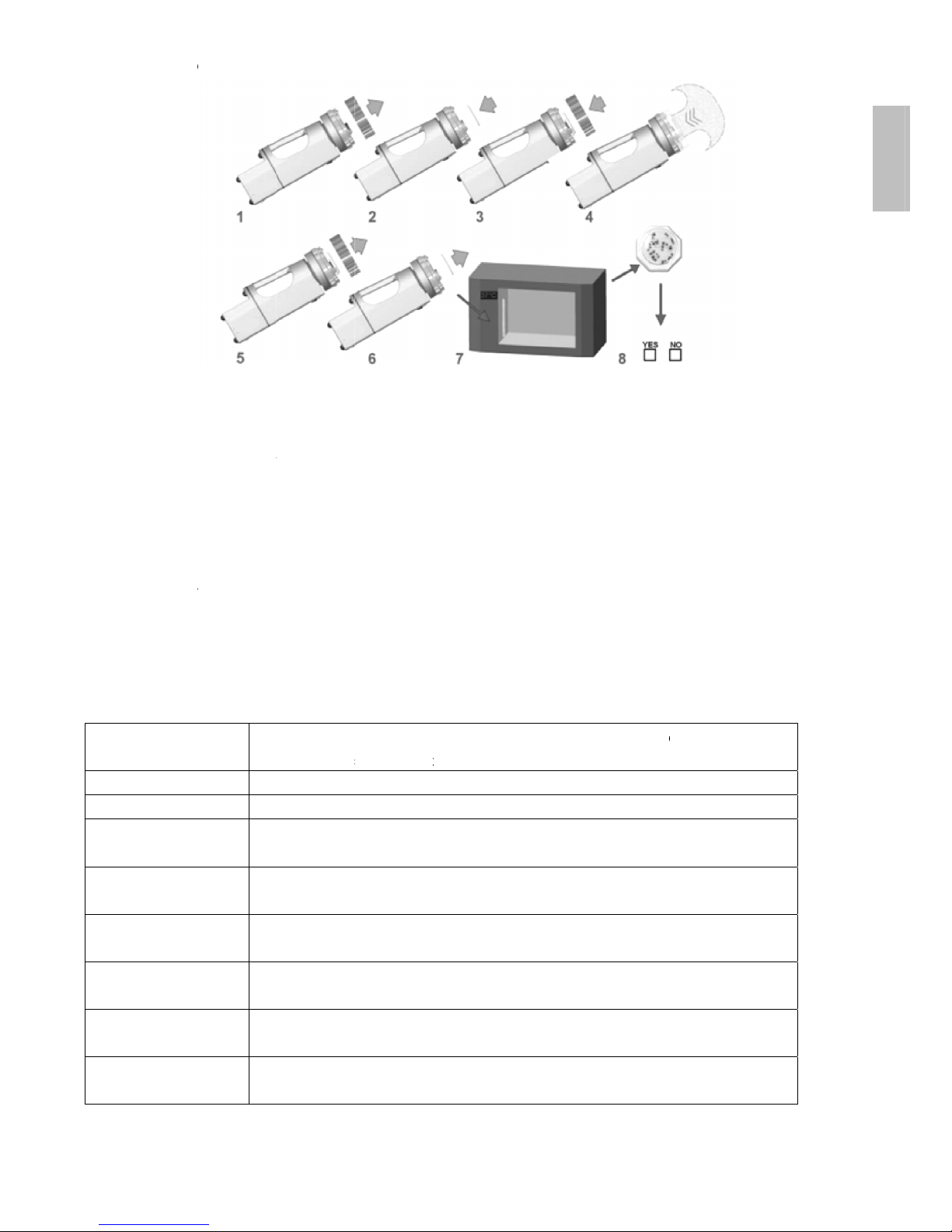
ctical use
o
1. Rem
o
2. Inser
t
3. Repl
a
4. Sele
c
5.
A
t th
e
6. Clos
e
7. Incub
8. Coun
t
of menus
RT FOR X
X
R MODE
ITY MODE
U
f contact
ve the aspi
r
an identifie
d
ce the aspi
r
t required ai
end of the
c
and remov
e
ate.
the colonie
and utilit
y
Thi
(X
XWit
Thi
SE
To
SA
To
ID
E
To
LA
N
To
CL
To
DI
S
To
plates
ating head.
, closed an
d
ating head.
rflow and st
a
ycle, remo
v
the plate.
s, recording
sub men
u
s message i
X) after pre
s
h this functi
o
s leads to th
T TIME
adjust the d
a
MPLING SI
T
identify the
s
NTIFY
identify the
o
GUAGE
display text
EAR RECO
R
clear the re
c
PLAY REC
O
show the re
c
prepared
prt
the unit.
T
e the aspira
t
the results
o
s
ndicates the
sing the ‘S
t
n you can t
o
e following
s
te and time
E
ampling po
i
perator’s n
a
in different l
a
D
orded sam
p
RD
orded sam
p
9
late and re
m
he airflow i
s
ing head.
n the micro
b
air sampler
art’ button
modify the
ub menu:
nt
me
nguages
ling data
ling data
ove the pla
t
directed in
t
iological air
is ready to
s
8 program
m
e lid.
o the agar s
sampling re
ample the v
o
able sampli
n
urface of th
e
port and rea
lume show
n
g volumes
plate.
d the result
s
.
ENGLISH

10
AUTO SWITCH OFF
To disconnect the automatic switch-off when the ‘Infrared Remote’ is used
PRINT
To export the recorded sampling data
MODE
To select the aspiration mode between single and multiple
CALIBRATION DUE
To check the calibration due date
Preliminary inspection
The apparatus is subject to specific quality tests before shipment and is carefully packed to avoid possible damage
during transit. However, a visible check should be carried out as soon as possible to determine any damage. This
must be reported immediately. The following procedures should be followed to check that the unit is working
properly.
The battery pack of the instrument must be charged for at least 14 hours before running the test.
After the ‘ON/OFF’ button is pressed an automatic visual presentation will be displayed.
Holder adjustment
The contact plate and Petri dish holders can be adjusted (using a screw driver) in case the available plates is slightly
different in diameter from the standard 55 mm contact plate or 90 mm Petri dish.
Petri head adapter (optional)
An adapter is available in aluminium or stainless steel which allows the use of standard 90 mm Petri dishes with
SAS for contact plates.
90 mm Petri dish filling
We recommend you fill the standard 90 mm disposable Petri dish with no more than 18 - 20 ml of agar to avoid the
medium touching the inside surface of the aspirating head.
Tripod installation (optional)
The SAS can be fixed to a table, floor tripod or wall support. The screw thread connection is located under the unit,
between the two front feet.
When not in use, the connection cavity is protected by a metal screw insert.
Functions
Operations
Press the ‘ON/OFF’ switch (black button) to switch on the unit.
The ‘ON/OFF’ switch (black button) must be pushed twice to switch the unit on if the automatic switch-off timer was
used previously.
Press ‘CLEAR’ at any time to return to the initial ‘START FOR’ main screen.
The air sampler is provided with eight fixed air volumes (‘Standard Mode’) stored in the memory and eight
programmable air volumes (‘USER MODE’) selectable by the operator.
Volume selection is made by pressing the “▲” or “▼” arrows when the programme is in the relevant sub menu.
ENGLISH

11
Suggested air volumes:
- Contaminated areas (communities, processing rooms, etc) 10 - 200 litres of air
- Normal areas (laboratory benches, houses, etc) 200 - 500 litres of air
- Sterile or high risk areas (cleanrooms, operating theatres, etc) 500 - 1000 litres of air.
Start with the same air volume as the previous sample
SAS SUPER ISOLATOR
Switch on the SAS using the ‘ON/OFF’ switch. You will then see the following display with the last aspirated volume
of air:
START FOR XXX
MM/DD/YY - HH:MM
Push the ‘START’ button to start a sampling cycle with the displayed volume of air.
[ XX] → XXX
MM/DD/YY - HH:MM
DUO SAS SUPER 360 - DUO SAS Isolator
Switch on the SAS using the ‘ON/OFF’ switch. You will then see the following display with the last aspirated volume
of air:
SELECT HEAD
Select the desires head by using the “▲” or “▼” arrows and press ‘ENTER’, the main screen will be displayed
START FOR XXX
MM/DD/YY - HH:MM
Push the ‘START’ button to start a sampling cycle with the displayed volume of air.
[ XX] → XXX
MM/DD/YY - HH:MM
‘STANDARD MODE’
The standard mode function allows the operator to select a sampling volume from a list of eight standard volumes.
Switch on the instrument and wait until the main screen is displayed:
START FOR XXX
MM/DD/YY - HH:MM
Press the “▼” or “▲” arrows to reach the
STANDARD MODE
MM/DD/YY - HH:MM
ENGLISH

12
Press the ‘ENTER’ button, now you can scroll the eight sampling volume. The selectable volumes are 10, 20, 30, 50,
100, 200, 500, 1000 litres).
S.PROG XXXX
MM/DD/YY - HH:MM
Once the desired sampling volume has been reached press the ‘ENTER’ button to confirm. The instrument is now
ready to sample the selected volume of air. Press the ‘START’ button to begin the sampling cycle
START FOR XXX
MM/DD/YY - HH:MM
‘USER MODE’
If the operator wish to use volumes other than the standards volumes, up to 8 additional volumes can be
programmed into the unit.
The user-selectable volumes can be selected from the USER MODE, while the selectable volumes can be modified
using the PROGRAM MODE function describe in the next paragraph. Switch on the instrument and wait until the
main screen is displayed:
START FOR XXX
MM/DD/YY - HH:MM
Press the “▼” or “▲” arrows to reach the
USER MODE
MM/DD/YY - HH:MM
Press the ‘ENTER’ button, now you can scroll the eight user-defined sampling volumes.
S.PROG XXXX
MM/DD/YY - HH:MM
Once the desired sampling volume has been reached press the ‘ENTER’ button to confirm. The instrument is now
ready to sample the selected volume of air. Press the ‘START’ button to begin the sampling cycle
START FOR XXX
MM/DD/YY - HH:MM
The total number of available ‘USER MODE’ programmes is eight. The maximum volume of air for each sampling
cycle is 1999 litres.
‘PROGRAM MODE’
Using this procedure, it is possible to memorise up to eight different volumes (from 1 to 1999 litres of air).
(See chapter 4.4.).
ENGLISH

13
Switch on the instrument and wait until the main screen is displayed:
START FOR XXX
MM/DD/YY - HH:MM
Press the “▼” or “▲” arrows to reach the
PROGRAM MODE
MM/DD/YY - HH:MM
Press the ‘ENTER’ button, now you can scroll the eight user-selectable sampling volumes.
S.PROG XXXX
MM/DD/YY - HH:MM
Once the sampling volume to be modified has been reached, press the ‘ENTER’ button to confirm.
The display will show the old and the new volume.
XXX → 0000
MM/DD/YY - HH:MM
Press the “▼” or “▲” arrows to select the first digit and press ‘ENTER’ to confirm
XXX → X000
MM/DD/YY - HH:MM
Press the “▼” or “▲” arrows to select the second digit and press ‘ENTER’ to confirm. Repeat the previous step until
the last digit is reached. When the last digit is confirmed, the new volume will be memorised and added to the list of
eight user-selectable volumes. If you want to start a sampling cycle with the new value you have to enter the USER
MODE and select it by using the procedure described in the USER MODE paragraph.
‘DELAY MODE’
With this function it is possible to delay the beginning of the sampling cycle. If a delay has been selected, the
sampling cycle will begin after the selected delay time.
Switch on the instrument and wait until the main screen is displayed:
START FOR XXX
MM/DD/YY - HH:MM
Press the “▼” or “▲” arrows to reach the
DELAY MODE
MM/DD/YY - HH:MM
Press the ‘ENTER’ button, the delay time is displayed
DELAY 01 MIN
MM/DD/YY - HH:MM
Select the desired delay time with the “▼” or “▲” arrows. The selectable delay values are 1, 2, 3, 5, 10 or
ENGLISH

14
20 minutes. Press ‘ENTER’ button to confirm.
When a delay has been selected, after the ‘START’ button has been pressed, a delay warning message will be
displayed
** D E L A Y **
‘MULTIMODE’
This programme is very useful for extending the time of sampling with the purpose of obtaining a more
representative environmental sample “in actual operating conditions”. The total air volume to be sampled is
aspirated with two or more sub volume aspirations (e.g.:1000 litres in ten runs of 100 litres at five minute
intervals).
Before entering ‘MULTI MODE’ you should decide:
(a) Total volume of air to be sampled onto the contact plate.
(b) Number of runs.
(c) Interval time between runs.
Switch on the instrument and wait until the main screen is displayed:
START FOR XXX
MM/DD/YY - HH:MM
Press the “▼” or “▲” arrows to reach the
MULTI MODE
MM/DD/YY - HH:MM
Press the ‘ENTER’ button, the interval time is displayed
INTERVAL TIME
05 MIN
Select the desired interval time between runs with the “▼” or “▲” arrows. The selectable interval values are 5, 10,
15, 20, 25, 30, or 60 minutes.
Press the ‘ENTER’ button to confirm the interval time, the numbers of runs is then displayed
NUMBER OF RUNS
20 NC
Select the desired number of cycles with the “▼” or “▲” arrows. The selectable values are 2, 3, 4, 5, 6, 7, 8,
9, 10, 15 or 20 runs.
Press the ‘ENTER’ button to confirm the number of runs, the single run volume is then displayed.
SINGLE RUN VOL.
XXXX
Select the desired digit using the “▼” or “▲” arrows then press the ‘ENTER’ button to skip to next digit.
When all the digits have been selected the total volume is displayed.
TOT. L. XXXX
ENGLISH

15
Press the ‘ENTER’ button to confirm.
NOTE: Before running multimode sampling, set the aspirating mode to MULTIMODE (see UTILITY MODE
paragraph)
Starting a multimode sampling cycle
Before running multimode sampling, set the aspirating mode to MULTIMODE (see chapter 4.8.2).
When the sampler aspiration mode is set to MULTIMODE, the main display will alternately show the number of
cycles and the volume of each cycle:
START FOR
MM/DD/YY - HH:MM
NC 02x1000 L.
MM/DD/YY - HH:MM
Press the ‘START’ button to run multiple sampling, the display will show the aspirating volume in the first row and
the residual number of the cycle in the second row:
[ XX] → XXX
- 02 CYCLES
At the end of the run, during the interval, the number of “residual cycles” (runs) that are remaining are shown on the
display:
- 02 CYCLES
** D E L A Y **
UTILITY MODE’
With this function it is possible to modify all the settings of the air sampler. The UTILITY MODE is divided into ten
sub menus:
Set time; Mode; Set Autoswitch; Print; Display Record; Clear Record; Language; Identify; Sampling site; Calibration
due.
Always start from UTILITY MODE to reach one of these sub menus. Switch on the instrument and wait until the
main screen is displayed:
START FOR XXX
MM/DD/YY - HH:MM
Press the “▼” or “▲” arrows to reach the
UTILITY MODE
MM/DD/YY - HH:MM
Press the ‘ENTER’ button, the first sub menu is listed.
ENGLISH

16
‘SET TIME’
From the UTILITY MODE select the ‘SET TIME’ function
This option is used to programme day, month, year and time of the day.
SET TIME
MM/DD/YY - HH:MM
Press ‘ENTER’ and “▼” or “▲” arrows to change month
Press ‘ENTER‘ and “▼” or “▲” arrows to change day
Press ‘ENTER’ and “▼” or “▲” arrows to change year
Press ‘ENTER’ and “▼” or “▲” arrows to change hours
Press ‘ENTER’ and “▼” or “▲” arrows to change minutes
Press ‘ENTER’ to confirm and exit.
‘MODE’
From the UTILITY MODE select the ‘MODE’.
This option is used to select the aspirating mode between SINGLE MODE and MULTIMODE.
MODE
MM/DD/YY - HH:MM
Press ‘ENTER’ and “▼” or “▲” arrows to change between SINGLE MODE and MULTIMODE
MULTI MODE
MM/DD/YY - HH:MM
SINGLE MODE
MM/DD/YY - HH:MM
Select the desired aspirating mode and press ‘ENTER’ to confirm and exit.
This setting will be stored in memory even after the instrument is switched off.
‘SET AUTOSWITCH’
To save battery consumption the SAS automatically switches off after 4 minutes. The SET AUTOSWITCH option is
used to enable or disable the automatic switch-off.
From the UTILITY MODE select the ‘SET AUTOSWITCH’
SET AUTOSWITCH
MM/DD/YY - HH:MM
Press ‘ENTER’ and “▼” or “▲” arrows to change between the two options.
AUTOSWITCH ON
MM/DD/YY - HH:MM
ENGLISH

17
AUTOSWITCH OFF
MM/DD/YY - HH:MM
Select the desired options and press ‘ENTER’ to confirm and exit.
This setting will be lost after the instrument is switched off.
‘PRINT’
The SAS can be connected with a RS232 cable to the SAS printer (Cat. No. ZZ30PCDPT100-I-12) or to a Personal
Computer with the SAS software (Cat. No. 710-0975). This function is used to start the data transfer form the SAS
to an external device.
From UTILITY MODE select the ‘PRINT’
PRINT
MM/DD/YY - HH:MM
Press ‘ENTER’ to start sending the data, the display will show:
SENDING DATA
For more information see the printer or software user manual.
‘DISPLAY RECORD’
The last 99 samples are memorised in the file ‘DISPLAY RECORD’. Each sample is identified in chronological
order and shows the date, time, operator, site and volume of air sampled.
From the UTILITY MODE select the ‘DISPLAY RECORD’.
DISPLAY RECORD
MM/DD/YY - HH:MM
Press ‘ENTER’ to see the memorised values
001 MM/DD HH:MM
ID. /SITE VOL. OP
The following parameters are recorded:
Progressive number; Month and Day; Time; Identification / Site; Sampling Volume; Option
If there is no data stored in memory the display will show
* * * * * * * * * * * *
* * * * * * * * * * * *
ENGLISH

18
‘CLEAR RECORD’
This option is used to delete all the data memorised in the DISPLAY RECORD. Before starting this procedure,
please be certain that existing data is not required or that it has been downloaded.
From the UTILITY MODE select the ‘CLEAR RECORD’.
CLEAR RECORD
MM/DD/YY - HH:MM
Press ‘ENTER’ to delete all the stored data, the display will show the resetting status
RESETTING...
►►►►
‘LANGUAGE’
Menu text can be selected choosing from different languages. From the UTILITY MODE select the ‘LANGUAGE’.
LANGUAGE
MM/DD/YY - HH:MM
Press ‘ENTER’ to list all the available languages,
ENGLISH
Use the “▼” or “▲” arrows to select the desired language and press ‘ENTER’ to confirm.
There are six available languages:
English, French, Spanish, German, Portuguese and Italian.
‘IDENTIFY’
This option is used to identify the operator. This should be changed if different operators use the sampler and
especially if the data is to be printed.
From the UTILITY MODE select the ‘IDENTIFY’.
IDENTIFY
MM/DD/YY - HH:MM
Press ‘ENTER’ to modify the identification code.
IDENTIFY
XXXX
Select the desired character using the “▲” or “▼” arrows and confirm with ‘ENTER’.
Select the next desired characters and confirm them by pressing ‘ENTER’.
The selected values are stored in the memory and it will be kept also after the instrument has been switched off.
‘SAMPLING SITE’
The site identification should be changed for samples taken at different sites especially if the results are to be
printed.
ENGLISH

19
From the UTILITY MODE select ‘SAMPLING SITE’ function.
SAMPLING SITE
MM/DD/YY - HH:MM
Press ‘ENTER’ to modify the sampling site
SAMPLING SITE
XXXX
Select the desired character using the “▲” or “▼” arrows and confirm with ‘ENTER’.
Select the next desired characters and confirm them by pressing ‘ENTER’.
The selected values are stored in the memory and it will be kept also after the instrument has been switched off.
‘CALIBRATION DUE’ (optional)
The SAS air sampler can be equipped with a calibration reminder feature. With this function the user can see when
the next calibration should be performed.
From the UTILITY MODE select the ‘CALIBRATION DUE’.
CALIBRATION DUE
MM/DD/YY - HH:MM
Press ‘ENTER’ to see the next calibration date:
NEXT CAL
MM/YYYY
The display shows the month in which the calibration should be performed.
One month before the calibration is due; the SAS will display the following warning message:
CALIBRATION DUE
MM/YYYY
When this message is displayed, press ‘ENTER’ to acknowledge.
When the calibration has expired, the SAS will display the following warning message:
CAL EXPIRED
When this message is displayed, press ‘ENTER’ to acknowledge.
The calibration timer can be reset only by a qualified technician.
List of system messages
Besides the messages described in the previous paragraph, the following messages can be displayed:
**LOW BATTERY** Battery must be recharged
MOTOR ERROR Motor not working or not connected
ENGLISH

20
- OFF The instrument is switching off
NEXT CAL The calibration due date is approaching
CAL EXPIRED The calibration due date has expired
Accessories
Description Cat. No.
Aspirating head for contact plates, Ø 55 mm
Stainless steel aspirating head for contact plates, Ø 55 mm 710-0880
Sterile daily head for contact plates, Ø 55 mm 710-0890
Aluminium aspirating head for contact plates, Ø 55 mm 710-0892
Aspirating head for Petri dishes, Ø 90 mm
Stainless steel aspirating head for Petri dishes, Ø 90 mm 710-0878
Sterile daily head for Petri dishes, Ø 90 mm 710-0891
Aluminium aspirating head for Petri dishes, Ø 90 mm 710-0886
Accessories
SAS Super universal battery charger 710-0993
Remote control 710-0962
Soft carrying case for DUO SAS 710-0888
Aluminium carrying case for DUO SAS 710-0876
Aluminium carrying case for SAS ISOLATOR 710-1022
Floor tripod 710-0889
SAS-Holder table and wall stainless steel 710-0963
Adaptor* to convert contact plate model to accept 90 mm Petri dishes 710-0882
SAS stainless steel Petri head + adaptor 710-0877
SAS aluminium Petri head + adaptor 710-0879
ENGLISH

21
Troubleshooting
Review the information in the table below to troubleshoot operating problems.
Problem Cause Solution
Unit does not start
Battery is low Recharge battery
Battery charger is not working Check battery charger and replace if
required (Cat. No. 710-0993)
Battery is too old Check battery and replace if required
Battery discharges after few minutes
working
Battery is low Recharge battery
Battery charger is not working Check battery charger and replace if
required (Cat. No. 710-0993)
Battery is too old Check battery and replace if required
“LOW BATTERY” message
Battery is low Recharge battery
“CAL EXPIRED” message
Instrument needs to be calibrated Send the instrument to VWR International
VWR or an authorised dealer
Infrared remote switch doesn’t switch
on the unit
Remote control battery is low Replace infrared remote battery
Microbiological media is dehydrated
after sampling
Media is corrupted Check expiration date of media and if the
agar was not dehydrated before sampling
Sampling time is too long Shorten the sampling time
ENGLISH

22
Technical service
Web resources
Visit the VWR website at vwr.com for:
• Complete technical service contact information
• Access to the VWR online catalogue and information about accessories and related products
• Additional product information and special offers
Contact us for information or technical assistance contact your local VWR representative or visit vwr.com
Warranty
VWR International warrants that this product will be free from defects in material and workmanship for a period of
two (2) years from date of delivery. If a defect is present, VWR will, at its option and cost, repair, replace, or refund
the purchase price of this product to the customer, provided it is returned during the warranty period. This warranty
does not apply if the product has been damaged by accident, abuse, misuse, or misapplication, or from ordinary
wear and tear. If the required maintenance and inspection services are not performed according to the manuals and
any local regulations, such warranty turns invalid, except to the extent, the defect of the product is not due to such
non-performance.
Items being returned must be insured by the customer against possible damage or loss. This warranty shall be
limited to the aforementioned remedies. IT IS EXPRESSLY AGREED THAT THIS WARRANTY WILL BE IN LIEU
OF ALL WARRANTIES OF FITNESS AND IN LIEU OF THE WARRANTY OF MERCHANTABILITY.
Compliance with local laws and regulations
The customer is responsible for applying for and obtaining the necessary regulatory approvals or other
authorisations necessary to run or use the product in its local environment. VWR will not be held liable for any
related omission or for not obtaining the required approval or authorisation, unless any refusal is due to a defect of
the product.
ENGLISH
23
Equipment disposal
This equipment is marked with the crossed out wheeled bin symbol to indicate that this equipment must not be
disposed of with unsorted waste.
Instead it's your responsibility to correctly dispose of your equipment at lifecycle -end by handing it over to an
authorised facility for separate collection and recycling. It's also your responsibility to decontaminate the equipment
in case of biological, chemical and/or radiological contamination, so as to protect from health hazards the persons
involved in the disposal and recycling of the equipment.
For more information about where you can drop off your waste of equipment, please contact your local dealer from
whom you originally purchased this equipment.
By doing so, you will help to conserve natural and environmental resources and you will ensure that your equipment
is recycled in a manner that protects human health.
Thank you
ENGLISH

24
Inhaltsverzeichnis
Warnung ..................................................................................................................................... 25
Sicherheitshinweise .................................................................................................................. 25
Beschreibungen des Geräts .................................................................................................... 26
Technische Daten ...................................................................................................................... 27
Verwendungszweck .................................................................................................................. 27
Kurzanleitung ............................................................................................................................ 28
Funktionen ................................................................................................................................. 31
„UTILITY MODE“ ....................................................................................................................... 36
Zubehör ...................................................................................................................................... 40
Problembehebung ..................................................................................................................... 41
Technischer Kundendienst ...................................................................................................... 42
Gewährleistung ......................................................................................................................... 42
Befolgung lokaler Gesetze und anderer Rechtsvorschriften ............................................... 42
DEUTSCH

25
Warnung
Das vorliegende Dokument ist Eigentum von VWR International S.r.l., Mailand, Italien
Es darf ohne Genehmigung des Eigentümers nicht dupliziert oder verteilt werden.
Zum Patent angemeldet
Hergestellt von VWR International S.r.l., Mailand, Italien
Sicherheitshinweise
Verwenden Sie das Gerät nur für den vorgesehen Zweck.
Vor der Verwendung des Geräts die Bedienungsanleitung sorgfältig lesen und befolgen.
Beschädigte elektrische Kabel umgehend austauschen.
Das Ladegerät vor folgenden Vorgängen immer trennen:
Reparatur oder Wartung; diese Vorgänge sind von qualifiziertem Personal durchzuführen
Reinigung des Geräts
Für den Austausch ausschließlich Originalersatzteile und Zubehör verwenden.
Das Gerät nicht in Umgebungen mit entzündlichem Gas verwenden.
Bitte die nachstehenden Anweisungen befolgen und diese Bedienungsanleitung sorgfältig durchlesen, um einen
sicheren Betrieb des Geräts zu gewährleisten.
Darauf achten, dass Spannung und Frequenz des elektrischen Systems den Anforderungen des
Akkuladegeräts entsprechen.
Niemals ein Ladegerät, das nicht vom Originalhersteller stammt, zum Laden des Luftkeimsammlers
benutzen.
Die Verwendung eines ungeeigneten Ladegeräts kann das Gerät beschädigen.
DEUTSCH
26
Beschreibungen des Geräts
15. Steuereinheit
16. Edelstahlkopf
17. Motorgehäuse
18. Taste „Clear“
19. Taste „Enter“
20. Pfeile nach oben
21. Taste „Start“
22. Pfeil nach unten
23. Standfüße
24. Drucker-Anschluss (nicht verwendet)
25. Hauptschalter
26. Seriennummer
27. CE-Kennzeichnung
28. Ladegerät-Anschluss
DEUTSCH
27
Technische Daten
Modell DUO SAS 360 Contact DUO SAS 360
Petri
DUO SAS ISOLATOR
Contact
DUO SAS
ISOLATOR Petri
Best.-Nr. 710-0867 710-0866 710-0977 710-0978
Luftstrom 180 l/min 180 l/min 180 l/min 180 l/min
Verwendet mit 55-mm-Abklatschplatten 90-mm-Petrischalen 55-mm-Abklatschplatten 90-mm-Petrischalen
Tragbar Ja Ja Ja Ja
Batterie Wiederaufladbar Wiederaufladbar Wiederaufladbar Wiederaufladbar
Batterielaufzeit 40 000 l 40 000 l 40 000 l 40 000 l
Modell ISOLATOR 100
Contact
ISOLATOR 180
Contact
ISOLATOR 100
Petri
ISOLATOR 180
Petri
Best.-Nr. 710-0943 710-0944 710-0945 710-0946
Luftstrom 100 l/min 180 l/min 100 l/min 180 l/min
Verwendet mit 55-mm-Abklatschplatten 55-mm-Abklatschplatten 90-mm-Petrischalen 90-mm-Petrischalen
Tragbar Ja Ja Ja Ja
Batterie Wiederaufladbar Wiederaufladbar Wiederaufladbar Wiederaufladbar
Batterielaufzeit 70 000 l 40 000 l 70 000 l 40 000 l
Verwendungszweck
Funktionsprinzip
Das Surface Air System (SAS, Oberflächen-Luft-System) umfasst mehrere Modelle, die auf dem gleichen
Funktionsprinzip beruhen. Luft wird mit einer festen Geschwindigkeit über einen variablen Zeitraum durch einen
Entnahmekopf angesaugt, der eine Reihe von kleinen Bohrungen mit einer speziellen Konstruktion aufweist. Die
resultierende Laminarströmung wird auf die Agar-Oberfläche einer RODAC-Platte (oder Petrischale) gelenkt, die ein
Nährmedium für die mikrobiologische Untersuchung enthält.
Wenn der gewählte Probenahmezyklus abgeschlossen ist, wird die Platte entfernt und inkubiert. Die Organismen
sind dann mit bloßem Auge erkennbar und können zur Beurteilung des Kontaminationsgrads gezählt werden.
DEUTSCH

28
Grundkonzept
Die Hauptmerkmale des Surface Air Systems (SAS) sind folgende:
8. Verwendung einer einfachen und preisgünstigen „Abklatschplatte“ („SURFAIR PLATE“, „RODAC“) für
Oberflächen-, Hand- oder Luftsteuerung. Diese gängigen und problemlos erhältlichen Platten können mit
unterschiedlichen Nährmedien vorgefüllt erworben werden.
9. Entnahme eines bekannten Luftvolumens über einen variablen Zeitraum zur Bereitstellung eines
Spektrums an Probenvolumen.
10. Ansaugung von Luft in einer Laminarströmungsstruktur mit ausreichender Geschwindigkeit, um
Organismen auf eine Agar-Oberfläche zu schießen.
11. Sammlung von Daten zum Hygieneniveau in jeder Umgebung, um die Fluktuationen zu überwachen.
12. Nutzung hochentwickelter Elektronik für zuverlässigere Ergebnisse bei unterschiedlichen
Betriebsbedingungen.
13. Flexibilität der Auswahl zwischen 55-mm-Abklatschplatten und 90-mm-Standard-Petrischalen.
14. Organisation einer sequenziellen Probenahme für repräsentativere Proben unter tatsächlichen
Betriebsbedingungen.
Kurzanleitung
Kurzanleitung für SAS Isolator
Der Luftstrom wird bei jedem Einschalten des Geräts nach der automatischen Darstellungsabfolge angezeigt.
Betriebsschalter „ON/OFF“ drücken.
Die Taste „START“ drücken, um das gleiche Luftvolumen wie beim letzten Probenahmezyklus zu entnehmen.
Zur Änderung des Luftvolumens mit Hilfe der Pfeiltasten „Standard Mode“ aus dem Menü wählen.
Für Änderungen der Einstellungen die Bedienungsanleitung heranziehen.
Zur Bestätigung der Auswahl „ENTER“ drücken.
Menüs mit Hilfe der Pfeiltasten auswählen, um weitere voreingestellte Parameter zu ändern:
STANDARD MODE
USER MODE
PROGRAM MODE
DELAY MODE
MULTI MODE
UTILITY MODE
„ENTER“ drücken, um das Untermenü des gewählten Parameters aufzurufen.
Hinweise zum Ändern der Einstellungen finden Sie in der Bedienungsanleitung.
Am Ende der Probenahme den Betriebsschalter „ON/OFF“ drücken.
Jedes Mal „CLEAR“ drücken, wenn eine Aktion abgebrochen werden soll. Das Gerät wird dann auf seine
ursprüngliche Konfiguration zurückgesetzt.
Kurzanleitung für DUO SAS Super 360 - DUO SAS Isolator
DEUTSCH

Sch
wWen
Mit
d
Zur
Die
Zur
Pra
Me
n
ST
AUSE
UTI
L
arzen Betr
i
n auf dem
D
en Auf- un
d
Bestätigung
Taste „STA
R
Änderung d
e
ktischer E
i
9. Den
S
10. Eine
g
11. Den
S
12. Den
g
Agar
-
13. Den
S
14. Die P
15. Inkub
16. Die
K
und
d
üs und U
n
RT FOR X
X
R MODE
ITY MODE
ebsschalter
isplay die
M
Abwärtspf
e
der Auswa
h
T“ drücken
,
s Luftvolu
m
nsatz der
A
augkopf ab
ekennzeic
h
augkopf wi
e
ewünschte
n
Oberfläche
d
augkopf a
m
latte schließ
ieren.
olonien zähl
ie Ergebnis
s
termenüs
Di
e
„St
a
Mit
we
Fü
h
SE
„ON/OFF“ d
eldung „SE
L
ile die Optio
l „ENTER“
d
um das gle
i
ens oder w
e
bklatsch
p
nehmen.
nete, gesch
l
der aufsetz
e
Luftstrom
a
er Platte g
e
Ende des
Z
en und entf
e
en, die Erge
e bewerten.
se Meldung
rt“ zur Entn
dieser Fun
k
rden.
rt zum folg
e
T TIME
rücken.
ECT HEA
D
n „LEFT HE
A
rücken.
che Luftvol
u
iterer Para
m
latten
ossene und
n.
uswählen, u
lenkt.
yklus entfer
rnen.
bnisse in de
gibt an, das
ahme des a
n
tion können
nden Unter
m
29
“ angezeigt
w
D“, „RIGH
T
men wie be
i
eter die An
w
vorbereitet
e
nd das Ger
ä
nen.
n Bericht für
s der Luftke
i
gezeigten
V
die 8 progr
a
enü:
ird, „ENTE
HEAD“ od
e
der letzten
eisungen f
ü
Platte eins
e
t starten. D
e
die mikrobi
e
msammler
n
olumens b
e
mmierbare
n
R“ drücken.
r „LEFT+RI
G
Probenahm
e
r SAS ISO
L
tzen und de
r Luftstrom
w
lle Luftkeim
ach dem D
r
reit ist.
Entnahme
v
HT HEAD“
zu entneh
m
ATOR verw
e
n Plattende
c
ird auf die
bestimmung
ücken der T
a
olumen ver
ä
wählen.
en.
nden.
kel entferne
eintragen,
ste
ndert
n.
DEUTSCH

30
Zur Einstellung von Datum und Uhrzeit.
PROBENAHMESTELLE
Zur Angabe des Ortes für die Probenahme.
ID
Zur Angabe des Namens des Benutzers.
LANGUAGE
Zum Anzeigen des Textes in unterschiedlichen Sprachen.
CLEAR RECORD
Zum Löschen der aufgezeichneten Probendaten.
MENU DISPLAY RECORD
Zum Anzeigen der aufgezeichneten Probendaten.
AUTO SWITCH OFF
Zur Deaktivierung der automatischen Abschaltung bei Nutzung der
Infrarot-Fernbedienung.
PRINT
Zum Exportieren der aufgezeichneten Probendaten.
MODE
Zum Auswählen des Ansaugmodus zwischen Einzel- und Multimodus.
CALIBRATION DUE
Zum Überprüfen des Fälligkeitsdatums der Kalibrierung.
Erste Inspektion
Das Gerät wird vor der Auslieferung spezifischen Qualitätstests unterzogen und sorgfältig verpackt, um einer
möglichen Beschädigung während des Transports vorzubeugen. Es sollte jedoch so bald wie möglich eine
Sichtprüfung durchgeführt werden, um etwaige Schäden festzustellen. Diese sind unverzüglich zu melden. Die
folgenden Arbeitsschritte sind durchzuführen, um zu überprüfen, ob das Gerät korrekt funktioniert.
Vor Durchführung des Tests ist der Akku des Geräts mindestens 14 Stunden lang aufzuladen.
Nach dem Drücken des Betriebsschalters „ON/OFF“ erscheint eine automatische Anzeigeabfolge.
Halteranpassung
Die Abklatschplatten- und Petrischalenhalter können verstellt werden (mit einem Schraubendreher) falls sich der
Durchmesser der verfügbaren Platten geringfügig von der 55-mm-Standard-Abklatschplatte oder
90-mm-Petrischale unterscheidet.
Petrischalenadapter (optional)
Ein Adapter aus Aluminium oder Edelstahl ist erhältlich, der die Verwendung von 90-mm-Standard-Petrischalen mit
dem SAS für Abklatschplatten ermöglicht.
Befüllen von 90-mm-Petrischalen
Wir empfehlen, die 90-mm-Standard-Petrischale für den Einmalgebrauch mit nicht mehr als 18–20 ml Agar zu
befüllen, um zu verhindern, dass das Nährmedium mit der Innenfläche des Ansaugkopfs in Kontakt kommt.
Installation des Stativs (optional)
Das SAS kann an einem Tisch-/Bodenstativ oder einer Wandhalterung befestigt werden. Das Schraubgewinde
befindet sich unten am Gerät, zwischen den beiden vorderen Standfüßen.
Wenn sie nicht verwendet wird, wird die Gewindeöffnung durch eine Metallschraube geschützt.
DEUTSCH
 Loading...