

VWR International Compact Star CS4 Instruction Manual
VWR Compact Star CS4
INSTRUCTION MANUAL
European Catalogue Numbers:
Euro Plug: 521-2853
UK Plug: 521-2854
Swiss Plug: 521-2855
Version: 1
Issued: 19. 11. 2008
Legal Address of Manufacturer
Europe
VWR International bvba
Haasrode Researchpark Zone 3
Geldenaaksebaan 464
B-3001 Leuven
+ 32 16 385011
http://be.vwr.com
Country of origin : USA
Intended Use:
The Centrifuge is a small bench top centrifuge designed for separation of various
samples for research, development, training, and education in the field of chemistry,
biotechnology, life-sciences, clinical research and routine diagnostics. The centrifuge is
supplied with a 6 x 15ml rotor. Adapters are available for tubes smaller than 10ml. The
centrifuge reaches speeds of up to 6,500rpm/4,000 x g.

Table of Contents
Warning 4
Safety information 4
Package Contents 5
Unpacking 5
Installation 5
Intended Use 5
Symbols and conventions 6
Specifications 6
Overview 6
Instructions for use 7
Troubleshooting 8
General maintenance 9
Accessories and spares 11
Use of Adapters 12
Tube Compatibility Chart 13
Determination of G-Values 13
Technical Service 15
Warranty 15
Disposal 16

Warning:
Please read this manual carefully prior to operating your VWR Centrifuge.
Safety Information:
NEVER use the centrifuge in any manner not specified in these instructions.
NEVER operate the centrifuge without a rotor properly attached to the shaft.
NEVER fill tubes while they are in the rotor. Liquid spillage may harm unit.
NEVER put hands in the rotor area unless the rotor is completely stopped.
NEVER move the centrifuge while the rotor is spinning.
NEVER use solvents or flammables near this or other electrical equipment.
NEVER centrifuge flammable, explosive or corrosive materials
NEVER centrifuge hazardous materials outside of a hood or proper containment facility
ALWAYS load the rotor symmetrically. Each tube should be counterbalanced by a tube of the
same type and weight
ALWAYS locate the centrifuge within easy access to an electrical outlet.
ALWAYS use only centrifuge tubes designed to withstand centrifugal forces of at least 4,000 xg.
ALWAYS use a wrench to tighten rotor nut
If this equipment is used in a manner not specified by the manufacturer, the
protection provided by the equipment may be impaired.
Do not operate the centrifuge if any of the following conditions exist:
-The centrifuge has not been installed properly
-The centrifuge is partially dismantled
-Service has been attempted by unauthorized or unqualified personnel
-The rotor has not been installed securely on the motor shaft
-Rotors and accessories not belonging to the standard range are being used without
permission being obtained from the manufacturer to use such rotors and/or accessories
in the centrifuge Exception: Centrifuge tubes, normally available in the laboratory.
-The centrifuge is located in an explosive atmosphere
-Materials to be centrifuged are combustible and/or explosive
-Materials to be centrifuged are chemically reactive
-The rotor load is not properly balanced
.
Package Contents:
Description Quantity
VWR Centrifuge 1
Rotor Removal Tool 1
Power Cord 1
Operations Manual 1
Adapter Set for 5 and 7ml tubes 1
Unpacking:
When unpacking your VWR Centrifuge, be sure to remove the protective foam
from the rotor chamber prior to operation.
DO NOT RUN THE CENTRIFUGE UNTIL THE FOAM HAS BEEN
REMOVED.
The accessories supplied with the centrifuge should be kept with the instruction manual
near the centrifuge’s place of installation.
Installation:
The centrifuge should be installed on a rigid, even surface such as a stable laboratory
bench, cabinet, etc. To guarantee sufficient ventilation, ensure that the centrifuge has at
least 15cm of free space on all sides, including the rear.
The centrifuge should not be located in areas subject to excessive heat such as in direct
sunlight or near radiators or the exhaust of a compressor, as a buildup of heat may
occur within the chamber.
Before operating the centrifuge, check that the power source corresponds to that on the
manufacturer’s rating label, then connect the power cord to the centrifuge and the power
source.
Symbols and conventions:
The following chart is an illustrated glossary of the symbols that are used in this manual.
CAUTION This symbol indicates a potential risk and alerts you to proceed with caution
B ard Warning This symbol indicates that BioHazardous Samples may be used in
ioHaz
this centrifuge, and proper precautions should be taken to prevent exposure. If BioHaza
material is processed in the centrifuge, use extra caution in handling sample vessels. Alway
wear gloves, safety goggles, and protective clothing. Safety precautions should be taken to
prevent exposure to aerosols or liquids that could be hazardous. In the event of a tube breakag
in the centrifuge, stop the centrifuge immediately and properly decontaminate according to
BioSafety Guidelines. The rotor and shields should be removed for complete decontaminat
these components. Information on decontaminants, their use, etc. are available in the Labo
Safety Manual published by the World Health Organization.
rdous
s
ion of
ratory
Product Specifications:
Maximum Volume 6 x 15ml (round bottom or conical) tubes
Dimensions
Width 210 mm
Depth 240 mm
Height 180 mm
Maximum speed 6,500rpm
Maximum RCF 4,000 x
Admissible density 1.2kg/dm
Electrical/fuse rating
230V~, 50-60Hz, 0.6A/1.25AT
Compliant to:
EN 61010: Safety requirements for electrical equipment for measurement, control, and
laboratory use
- Part 1: General requirements.
- Part 2 -020:
Particular requirements for laboratory centrifuges
- Part 2-101: Particular requirements for in vitro diagnostic (IVD) medical equipment
3
e
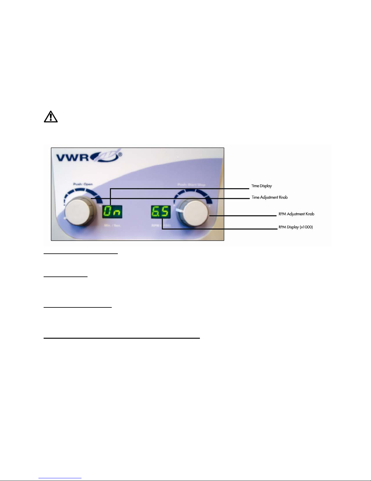
Overview:
This manual provides important safety information for the VWR Laboratory centrifuge. It
should be kept near the centrifuge for quick and easy reference.
Instructions for Use:
ATTENTION: Never attempt to operate the centrifuge with rotors or adapters
that show signs of corrosion or mechanical damage. Never centrifuge strongly
corrosive materials that may damage the rotors or accessories.
Closing the lid:
After the rotor has been properly secured and loaded, close the centrifuge lid, making
sure that the interlock has been engaged.
Lid lock:
The centrifuge can be started only with the lid securely closed. Do not attempt to open
the lid until the end of run signal “00” is displayed on both the “RPM Display” and “Time
Display”.
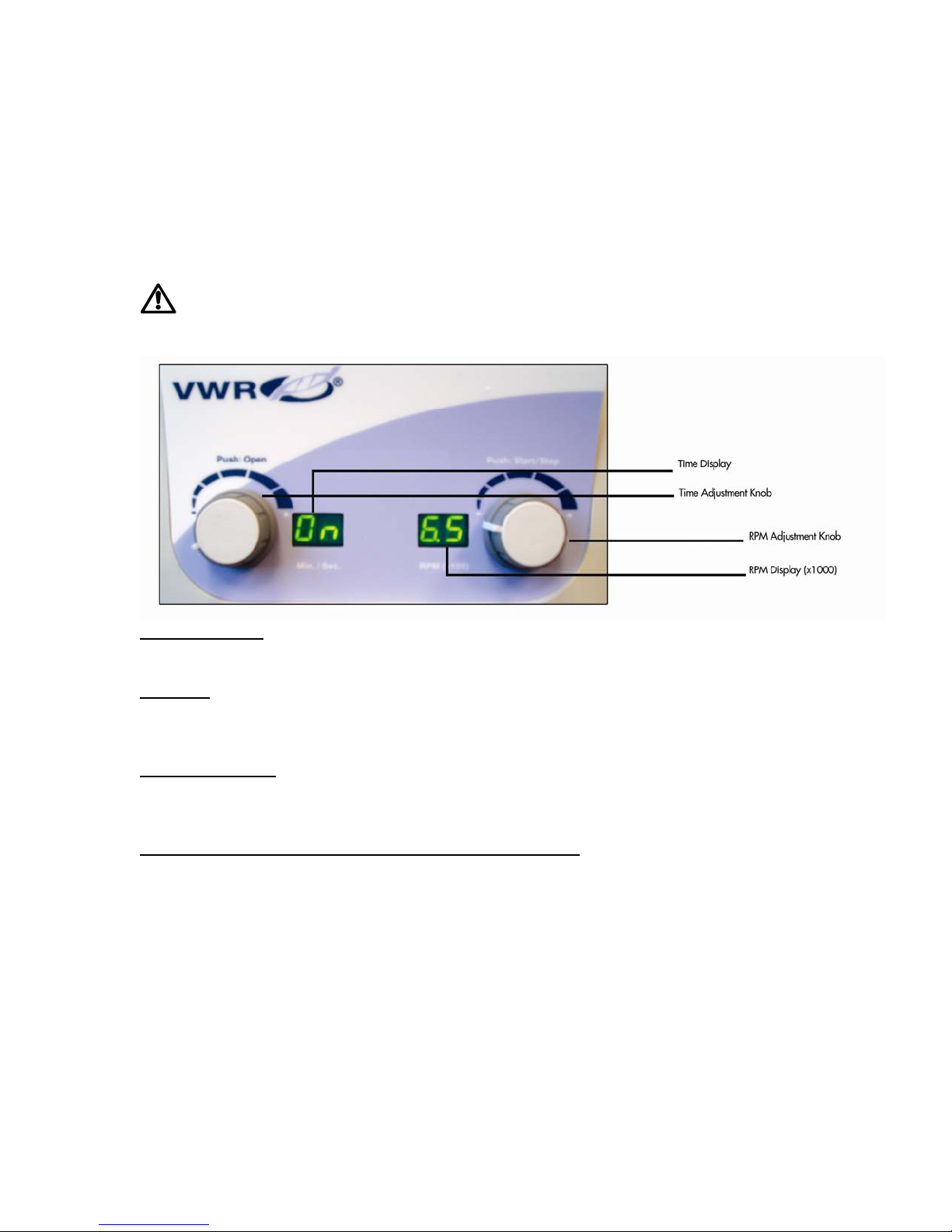
Speed selection:
The speed (rpm) can be selected from 300 to 6,500rpm with the “RPM Adjustment
Knob” (right). The set speed can be viewed at all times on the large “RPM Display”
(right).
Selection of operating time and momentary operation:
Time can be selected in half minute intervals from 0.5 to 10 minutes, and in one minute
intervals from 11 to 30 minutes. Time can also be set to continuous/hold by turning the
“Time Adjustment Knob” (left) past the thirty minute position. The “Time Display” in the
continuous setting will read “On”. When the pre-selected time expires, the centrifuge will
stop automatically. To stop the centrifuge prior to the expiration of set time, press the
“RPM Adjustment Knob” (right).

Quick spin function
The centrifuge may be operated manually by pressing and holding the “RPM Adjustment
Knob” (right). The centrifuge will continue to run as long as the knob is depressed.
Starting the centrifuge:
Once the time and speed have been selected the centrifuge can be started by pressing
the “RPM Adjustment Knob” (right). The centrifuge will then run for the specified amount
of time.
Lid release:
Following a run, the centrifuge will display will show flashing “00”. This signals the end of
a run and the lid can now be opened by pressing the “Time Adjustment Knob” (left). Note
that the lid can not be opened until the display flashes “00” and the rotor has stopped.
WARNING: Do not attempt to open the lid of any centrifuge until the rotor has
come to a complete stop.
In the event of a power failure or malfunction, it may be necessary to open the lid
manually.
1. Disconnect the power cord from the wall socket.
2. Remove the plastic plug, located on the left side of the unit.
3. Pull the cord (attached to the plug) to open the lid lock manually.
Troubleshooting:
Review the information in the table below to troubleshoot operating problems.
Please refer to this guide before calling for service.
Centrifuge will not start
Possible reason: No power supply
Solution: Check that power is being supplied to the outlet
Check that the power cord is plugged into both the wall outlet and
the back of
the centrifuge
Check that power cord is not damaged
Possible reason: Blown fuse
Solution: Check fuse and replace if necessary
Lid lock will not release
Possible reason: Defective lid lock
Solution: Open manually and have unit serviced
Possible reason: No power from PC board
Solution: Call for service
Possible reason: Lid lock is jammed
Solution: Call for service
Possible reason: Centrifuge is not receiving power
Solution: See “Centrifuge will not start”
Centrifuge cannot be started, although power is on
Possible reason: Lid not closed correctly
Solution: Close lid correctly
Possible reason: No speed or time has been selected
Solution: Set speed and/or time
Centrifuge displays error “03”
Possible reason: Lid opened prior to signal “00”.
Solution: Close lid and open lid
General maintenance:
If BioHazardous Materials have been used in the centrifuge, and it is removed
from usage for service or disposal, it must be properly disinfected according to standard
BioSafety Guidelines. See Disinfection, below.
Centrifuge service
The centrifuge requires no routine maintenance other than the occasional routine
cleaning. All repairs should be performed by authorized, qualified personnel only.
Repairs performed by unauthorized personnel may void the warranty.
Cleaning the centrifuge
Always keep the centrifuge housing, rotor chamber, rotor and rotor accessories clean.
All parts should be wiped down periodically with a soft cloth. For more thorough
cleaning, use a neutral cleaning agent (pH between 6 and 8) applied with a soft cloth.
Excessive amounts of liquid should be avoided. Liquid should not come into contact with
the motor. After cleaning, ensure that all parts are dried thoroughly by hand or in a warm
air cabinet (maximum temperature 50ºC).
Cleaning the rotor
The rotor should be cleaned after each use. When spinning
or phenol chloroform, the rotor should be cleaned immediately after use.
Disinfection
Should a spill of infectious materials occur within the rotor or chamber, the unit should be
disinfected. This should be performed by qualified personnel with proper protective
equipment. Information on decontaminants, their use, etc. are available in the Laboratory
Safety Manual published by the World Health Organization.
Autoclaving the rotor
The rotor and rotor shields can be autoclaved at 121°C for 20 minutes. Please be sure
to let the shields cool for 20 minutes before running them in the centrifuge.
Replacing fuses
Check the fuse when it is recommended in the Troubleshooting Guide located in this
manual. The fuse holder is located in the power inlet on the rear of the unit. Disconnect
the power cord from the power inlet. Open the fuse holder drawer by inserting a small
screwdriver under the tab and prying it open. Remove the
innermost (operative) fuse from its retaining tabs and replace the fuse if necessary. A
spare fuse is located in the outermost chamber of the fuse drawer. Replace only with a
fuse of exactly the same value as the original. (Fuse type may be found in the
“Specifications” section of this manual.)
samples containing phenol

Rotor maintenance
The rotor should be cleaned thoroughly after each use. Thorough cleaning must be
performed when spinning samples containing phenol or phenol chloroform.
Periodically inspect the rotor for dents, dings, scratches, discoloration and cracks. If any
damage to the rotor is found, discontinue use of the rotor
immediately and replace.
Removing and Installing the angle rotor
Remove the rotor screw from the motor shaft by turning the screw counterclockwise. Lift
the rotor upward and remove from the centrifuge. Ensure that the motor shaft adapter
remains on the motor shaft (Figure 1). Clean the motor shaft and motor shaft adapter
(see figure 1). Place the rotor on the motor shaft (figure 1) and over the motor shaft
adapter (see figure 1 and 2). Note: Figure 1 and 2 are located on the following page.
When loading the rotor, refer to figure 3 (located on the following page). Loading in the
pattern indicated will ensure a balanced load. Tubes to be loaded should be filled equally
by eye. The difference in the weight between the tubes should not exceed 5 grams. A
partially loaded rotor may be centrifuged if the loading
scheme for balancing a rotor given in figure 3 is followed.
Overloading the rotor
The maximum load of the rotor and the maximum speed have been established by the
manufacturer. Do not attempt to exceed these values. The maximum speed of the rotor
has been measured for liquids having a homogeneous density of 1.2g/ml or less. In
order to centrifuge liquids with a higher density it is necessary to reduce the speed.
Failure to reduce the speed may result in damage to the rotor and centrifuge.
The revised maximum speed can be calculated with the following formula
Reduced speed (n
red) x max speed
Example:
Where the density of the liquid is 1.7, the new maximum speed would be calculated as
follows:
red = x 6,500 = 5,461 rpm
If in doubt concerning maximum speeds, please contact the manufacturer for assistance.

User replaceable accessories and spare parts
The following accessories are available for the Centrifuge:
Angle rotor for 6 x 15ml tubes (included with unit)
Order no.: TR100 Qty.1
Tube measurement: 15ml (17x125mm)-10ml (16x100mm)
Max. speed: 6,500rpm
Centrifuging radius: 8.5cm
RCF (g-value): 4,000 x g
Rotor angle: 30°
Pack of 6 Adapters for 5ml (12x75mm) and 7ml (13x100mm) tubes
Order no.: 521-2856 (Included with CS4 model)
Tube measurement: 12x75mm, 13x100mm, or common branded style blood
collection tubes
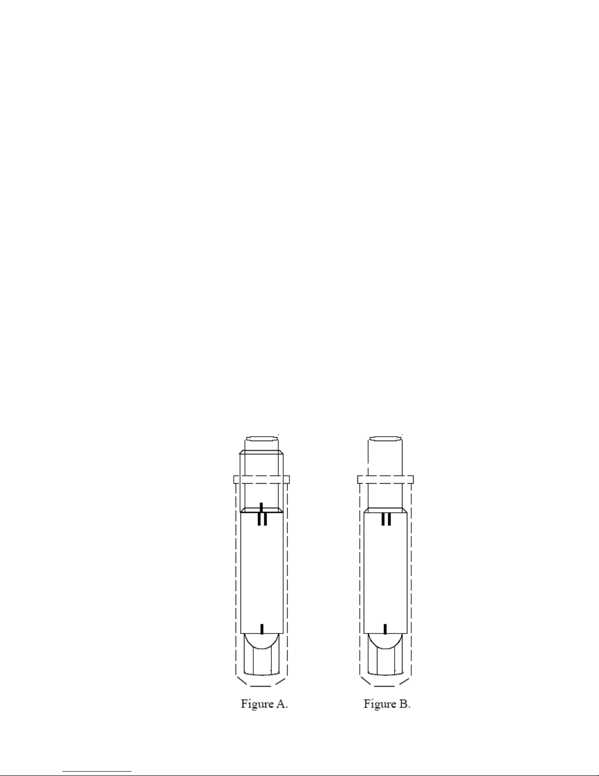
Use of tube adapters:
- Centrifuging 7ml tubes (13 x 100mm)
or any tube with a diameter of less than 14mm and
a height above 90mm. (Figure A.)
- Configure combination adapter so that
the single line mark lines up with
the double line mark.
- Place the adapter in the rotor shield
with the hollow side up
(per figure A.)
- Centrifuging 5ml tubes (12 x 75mm)
or any tubes with a diameter less than 14 and
a height below 90mm.
- Take the larger half of the combination
adapter and place it in the rotor
shield with the double line mark up
and the single line mark down
(per figure B.)
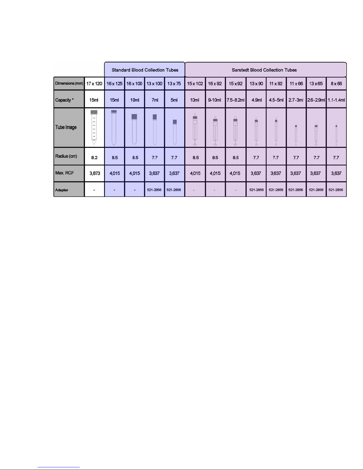
Tube Compatibility Chart:
Capacity may vary due to serum volume.
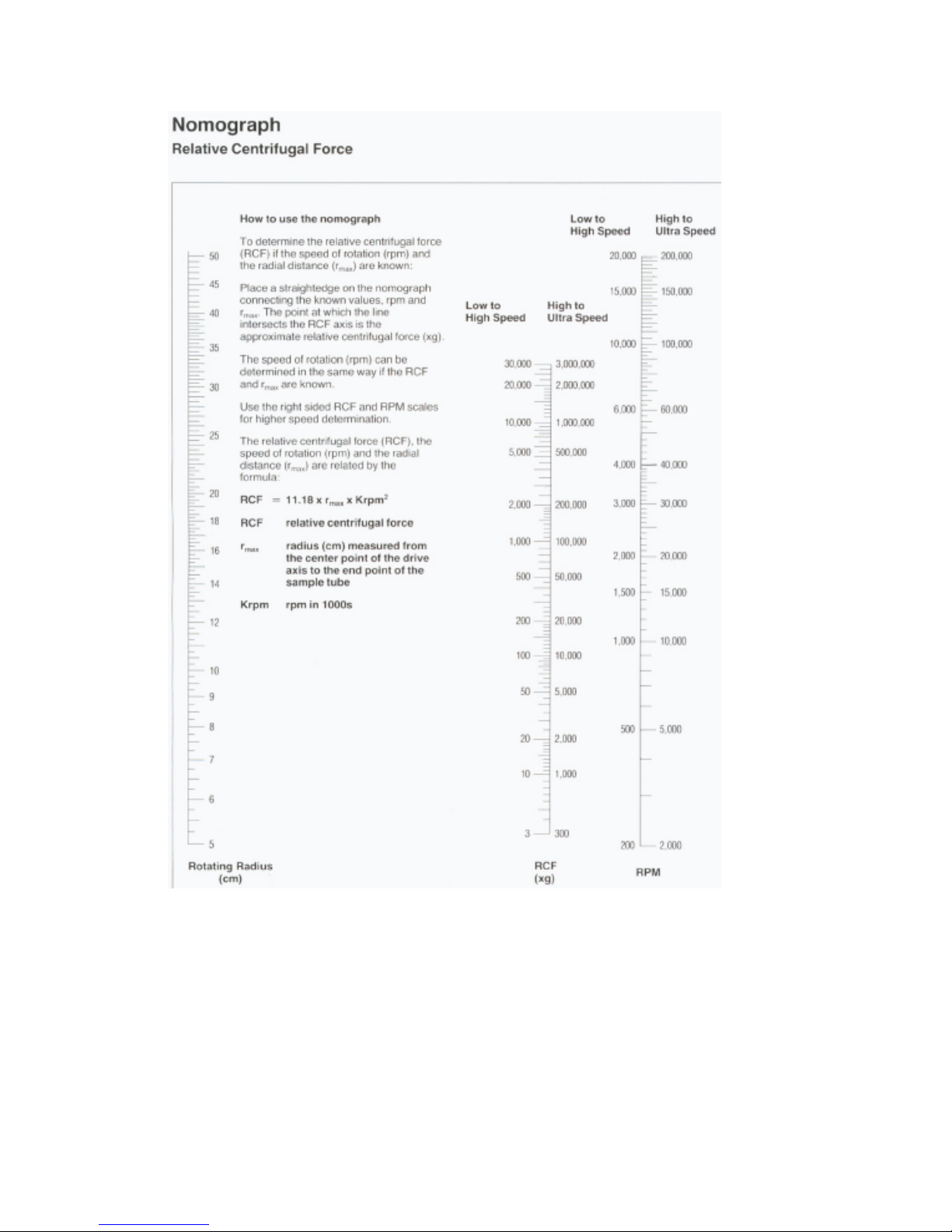
Determination of G-Values:
The centrifuging radius of the rotor is 8.5cm. See the tube compatibility chart for the
correct radius when using adapters and smaller tubes. The chart on the next page
can be used to determine g-values.
To use this chart, find the radius value on the radius scale. Place the edge of a ruler
on the value. Place the right side edge of the ruler on the speed scale at the desired
speed. The estimated RCF can then be read from the RCF scale where the ruler
edge passes through it. This chart can also be used to determine the proper speed
for the desired RCF value.

Technical service
Web Resources
Visit the VWR’s website at www.vwr.com for:
• Complete technical service contact information
• Access to VWR’s Online Catalogue, and information about accessories and related products
• Additional product information and special offers
Contact us For information or technical assistance contact your local VWR representative or
visit. www.vwr.com.
Warranty
VWR International warrants that this product will be free from defects in material and
workmanship for a period of two (2) years from date of purchase. If a defect is present, VWR will,
at its option, repair, replace, or refund the purchase price of this product at no charge to you,
provided it is returned during the warranty period. This warranty does not apply if the product has
been damaged by accident, abuse, misuse, or misapplication, or from ordinary wear and tear.
For your protection, items being returned must be insured against possible damage or loss. This
warranty shall be limited to the replacement of defective products. IT IS EXPRESSLY AGREED
THAT THIS WARRANTY WILL BE IN LIEU OF ALL WARRANTIES OF FITNESS AND IN LIEU
OF THE WARRANTY OF MERCHANTABILITY.
Equipment disposal
This equipment is marked with the crossed out wheeled bin symbol to indicate that this
equipment must not be disposed of with unsorted waste.
Instead it's your responsibility to correctly dispose of your equipment at lifecycle -end by handling
it over to an authorized facility for separate collection and recycling. It's also your responsibility to
decontaminate the equipment in case of biological, chemical and/or radiological contamination,
so as to protect from health hazards the persons involved in the disposal and recycling of the
equipment.
For more information about where you can drop off your waste of equipment, please contact your
local dealer from whom you originally purchased this equipment.
By doing so, you will help to conserve natural and environmental resources and you will ensure
that your equipment is recycled in a manner that protects human health.
Thank you

Local VWR offices in Europe
Austria
VWR International GmbH
Graumanngasse 7
1150 Wien
Tel.: 01 97 002 0
Fax: 01 97 002 600
E-mail: info@at.vwr.com
Belgium
VWR International bvba/sprl
Haasrode Researchpark Zone 3
Geldenaaksebaan 464
3001 Leuven
Tel.: 016 385 011
Fax: 016 385 385
E-mail:
customerservice@be.vwr.com
Denmark
VWR - Bie & Berntsen
Tra ns fo rmervej 8
2730 Herlev
Tel.: 43 86 87 88
Fax: 43 86 87 90
E-mail: info@dk.vwr.com
Finland
VWR International Oy
Pihatörmä 1 C 1
FI - 02240 Espoo
Tel.: +358 9 80 45 51
Fax: +358 9 80 45 52 00
E-mail: info@fi.vwr.com
France
VWR International S.A.S.
Le Périgares --- Bâtiment B
201, rue Carnot
94126 Fontenay-sous-Bois cedex
Tel.: 0 825 02 30 30 (0,15 EUR TTC/min)
Fax: 0 825 02 30 35 (0,15 EUR TTC/min)
E-mail: info@fr.vwr.com
Germany
VWR International GmbH
Hilpertstrasse 20a
D - 64295 Darmstadt
Tel.: 0180 570 20 00*
Fax: 0180 570 22 22*
E-mail: info@de.vwr.com
*14 Cent/Minute aus d. dt. Festnetz
ggf. Abweichungen Mobil-Funk-Tarife
Ireland
VWR International Ltd
Orion Business Campus
Northwest Business Park
Ballycoolin
Dublin 15
Tel.: 01 88 22 222
Fax: 01 88 22 333
e-mail sales@ie.vwr.com
Northern Ireland
VWR International Ltd
A10 Harbour Court, 7 Heron Rd
Sydenham Business Park
Belfast BT3 9HB
Tel.: 028 9058 5800
Fax: 028 9080 7812
e-mail sales@ie.vwr.com
Italy
VWR International s.r.l.
Via Stephenson 94
20157 Milano (MI)
Tel.: 02 332 03 11
Fax: 800 152 999
E-mail: info@it.vwr.com
The Netherlands
VWR International B.V.
Postbus 8198
1005 AD Amsterdam
Tel.: 020 4808 400
Fax: 020 4808 480
E-mail: info@nl.vwr.com
Norway
VWR International AS
Kakkelovnskroken 1
P.B. 45, Kalbakken
0901 Oslo
Tel.: 02290
Fax: 815 00 940
E-mail: info@no.vwr.com
Portugal
VWR International - Material de
Laboratório, Lda
Edifício Neopark
Av. Tomás Ribeiro, 43- 3 D
2790-221 Carnaxide
Tel.: 21 3600 770
Fax: 21 3600 798/9
E-mail: info@pt.vwr.com
Spain
VWR International Eurolab S.L.
Ronda Can Fatjó, nº 11
Edifici Tecnopark, 3
Parc Tecnològic del Vallés
08290 Cerdanyola del Vallés
(Barcelona)
Tel.: 902 222 897
Fax: 902 430 657
E-mail: info@es.vwr.com
Sweden
VWR International AB
Fagerstagatan 18a
163 94 Stockholm
Tel.: 08 621 34 00
Fax: 08 621 34 66
E-mail: info@se.vwr.com
Switzerland
VWR International AG
Lerzenstrasse 16/18
8953 Dietikon
Tel.: 044 745 13 13
Fax: 044 745 13 10
E-mail: info@ch.vwr.com
UK
VWR International Ltd
Customer Service Centre
Hunter Boulevard
Magna Park
Lutterworth
Leicestershire
LE17 4XN
Tel.: 0800 22 33 44
Fax: 01455 55 85 86
E-mail: uksales@uk.vwr.com
VWR Compact Star CS4
INSTRUCTION MANUAL
European Catalogue Numbers:
Euro Plug: 521-2853
UK Plug: 521-2854
Swiss Plug: 521-2855
Version: 1
Issued: 19, 11, 2008
Eingetragener Sitz des Herstellers
Europa
VWR International BVBA
Haasrode Researchpark Zone 3
Geldenaaksebaan 464
B-3001 Leuven
+ 32 16 385011
http://be.vwr.com
Herkunftsland : USA
Verwendungszweck:
Bei dieser Zentrifuge handelt es sich um eine kleine Tischzentrifuge, die für die Trennung
verschiedener Proben bei der Forschung und Entwicklung, Aus- und Weiterbildung in den
Bereichen Chemie, Biotechnologie, Biowissenschaften, klinische Forschung und RoutineDiagnose entwickelt wurde. Im Lieferumfang der Zentrifuge ist ein 6 x 15-ml-Rotor enthalten.
Für Röhrchen kleiner als 10 ml sind Adapter verfügbar. Die Zentrifuge erreicht Drehzahlen
von bis 6.500 u/min/ 4.000 x g.

Inhaltsverzeichnis
Warnung 4
Sicherheitshinweise 4
Verpackungsinhalt 5
Auspacken des Geräts 5
Installation 5
Verwendungszweck 5
Symbole und Konventionen 6
Spezifikationen 6
Übersicht 6
Gebrauchsanweisung 7
Problembehebung 8
Grundwartung 9
Zubehör und Ersatzteile 11
Verwendung von Adaptern 12
Kompatible Gefäße – Übersicht 13
Bestimmung von G-Werten 13
Technischer Kundendienst 15
Garantie 15
Entsorgung 16

Warnung:
Bitte lesen Sie vor der Inbetriebnahme der VWR Zentrifuge diese Anleitung aufmerksam
durch.
Sicherheitshinweise:
NIEMALS die Zentrifuge anders betreiben, als es in dieser Anleitung beschrieben ist.
NIEMALS die Zentrifuge in Betrieb nehmen, wenn der Rotor nicht richtig auf der Welle befestigt ist.
NIEMALS Röhrchen befüllen, während sich diese im Rotor befinden. Verschüttete Flüssigkeit kann
das Gerät beschädigen.
NIEMALS in den Rotorbereich greifen, wenn der Rotor nicht völlig stillsteht.
NIEMALS die Zentrifuge bewegen, während der Rotor dreht.
NIEMALS Lösungsmittel oder entzündliche Substanzen in der Nähe dieses oder anderer elektrischer
Geräte verwenden.
NIEMALS entzündliche, explosive oder korrosive Materialien zentrifugieren.
NIEMALS gefährliche Substanzen außerhalb eines Abzugs oder einer geeigneten Schutzeinrichtung
zentrifugieren.
IMMER den Rotor symmetrisch beladen. Jedes Röhrchen benötigt als Gegengewicht ein zweites
Röhrchen des gleichen Typs und mit dem gleichen Gewicht.
IMMER die Zentrifuge in der Nähe einer Netzsteckdose aufstellen.
IMMER ausschließlich Zentrifugenröhrchen verwenden, die für Zentrifugalkräfte von mindestens
4.000 x g ausgelegt sind.
IMMER zum Festziehen der Rotormutter einen Schraubenschlü ssel verwenden
Wird das Gerät nicht gemäß den Bestimmungen des Herstellers verwendet, kann dies
die Sicherheit des Geräts beeinträchtigen.
Verwenden Sie die Zentrifuge nicht, wenn einer der folgenden Mängel vorliegt:
-Die Zentrifuge wurde nicht richtig aufgestellt.
-Die Zentrifuge ist teilweise zerlegt.
-Es wurden Wartungsversuche von nicht autorisiertem oder unqualifiziertem Personal
unternommen.
-Der Rotor wurde nicht sicher auf der Antriebswelle installiert.
-Es werden Rotoren oder Zubehörteile mit der Zentrifuge verwendet, die nicht zum
Standardsortiment gehören, ohne eine entsprechende Zulassung durch den Hersteller
erhalten zu haben. Ausnahme: Normale, im Labor verfügbare Zentrifugenröhrchen.
-Die Zentrifuge wurde in einer explosionsgefährdeten Umgebung aufgestellt.
-Das zu zentrifugierende Material ist brennbar und/oder explosiv.
-Das zu zentrifugierende Material ist chemisch reaktiv.
-Der Rotor wurde ungleichmäßig beladen.
.
Verpackungsinhalt:
Bezelchnung Menge
VWR Zentrifuge 1
Rotor-Entnahmetool 1
Netzkabel 1
Bedienungsanleitung 1
Adaptersatz für 5- und 7-mlRöhrchen
1
Auspacken des Geräts:
Achten Sie darauf, dass Sie beim Auspacken der VWR Zentrifuge den
Schutzschaumstoff aus der Rotorkammer entfernen, bevor Sie das Gerät in Betrieb
nehmen.
SCHALTEN SIE DIE ZENTRIFUGE ERST EIN, NACHDEM DER
SCHAUMSTOFF ENTFERNT WURDE.
Das mit der Zentrifuge gelieferte Zubehör sollte zusammen mit der Bedienungsanleitung in
der Nähe des Installationsortes der Zentrifuge aufbewahrt werden.
Installation:
Die Zentrifuge wird auf einer festen, ebenen Oberfläche aufgestellt, z. B. auf einem stabilen
Labortisch, Schrank usw. Um eine ausreichende Belüftung zu gewährleisten, muss um die
Zentrifuge herum, einschließlich der Rückseite, mindestens 15 cm Freiraum gelassen
werden.
Die Zentrifuge muss vor übermäßiger Hitzeeinwirkung, z. B. direktem Sonnenlicht,
Heizkörpern oder der Abluft eines Kompressors, geschützt aufgestellt werden, da sich
ansonsten im Innern der Kammer Hitze entwickeln kann.
Stellen Sie vor der Inbetriebnahme der Zentrifuge sicher, dass die Stromquelle mit den
Angaben des Herstellers auf dem Typenschild übereinstimmt, und schließen Sie erst dann
das Netzkabel an die Zentrifuge und Stromquelle an.
Symbole und Konventionen:
In der folgenden Tabelle werden die Symbole erläutert, die in diesem Handbuch Verwendung finden.
ACHTUNG Dieses Symbol weist auf eine Gefahr hin. Gehen Sie vorsichtig vor.
Warnung bezüglich Biogefahrenstoffe Dieses Symbol gibt an, dass in dieser Zentrifuge
Biogefahrenstoffe verarbeitet werden können und dass spezielle Vorkehrungen getroffen werden
müssen, um eine mögliche Kontamination zu verhindern. Sollten in der Zentrifuge Biogefahrenstoffe
verarbeitet werden, muss bei der Handhabung der Probengefäße mit besonderer Vorsicht
vorgegangen werden. Tragen Sie stets Handschuhe, Schutzbrille und Schutzkleidun g. Um eine
Kontamination durch gefährliche Aerosole oder Flüssigkeiten zu verhindern, müssen geeignete
Sicherheitsvorkehrungen getroffen werden. Sollte es zu einem Gefäßbruch in der Zentrifuge
kommen, stellen Sie das Zentrifugieren sofort ein, und nehmen Sie eine ordnungsgemäße
Dekontamination entsprechend der Richtlinien für Biogefahren stoffe vor. Rotor und Abschirmungen
müssen abgenommen werden, um eine vollständige Dekontamination dieser Te ile zu gewährleisten.
Informationen zu Dekontaminationsmitteln und deren Verwendung usw. können Sie dem von der
Weltgesundheitsorganisation veröffentlichten „Laboratory Safety Manual“ (Handbuch zur
Laborsicherheit) entnehmen.
Produktspezifikationen:
Maximalvolumen 6 x 15-ml-Röhrchen (mit rundem oder konisch zulaufendem Boden)
Abmessungen
Breite: 210 mm
Tiefe: 240 mm
Höhe: 180 mm
Maximale Drehzahl 6.500 min-1
Maximale RZB 4.000 x
Zulässige Dichte 1,2 kg/dm
Elektrische Kenndaten/Sicherung
230 V~, 50-60 Hz, 0,6 A/1,25 AT
Normenkonformität:
EN 61010: Sicherheitsbestimmungen für elektrische Mess-, Steuer-, Regel- und Laborgeräte
- Teil 1: Allgemeine Anforderungen
- Teil 2-020:
- Teil 2-101:
Besondere Anforderungen an Laborzentrifugen
Besondere Anforderungen an In-vitro-Diagnostik (IVD)-Medizingeräte
3
Übersicht:
Dieses Handbuch enthält wichtige Sicherheitsinformationen zur VWR Laborzentrifuge. Es
sollte zur schnellen Referenz griffbereit in der Nähe der Zentrifuge aufbewahrt werden.
Gebrauchsanweisung:
ACHTUNG: Versuchen Sie niemals, die Zentrifuge mit Rotoren oder Adaptern zu
betreiben, die Anzeichen von Korrosion oder mechanischer Beschädigung auf weisen.
Zentrifugieren Sie niemals stark korrosive Materialien, die den Rotor oder das Zubehör
beschädigen könnten.
Schließen des Deckels:
Schließen Sie nach dem ordnungsgemäßen Sichern und Beladen des Rotors den
Zentrifugendeckel, so dass die Sperre einrastet.
Deckelsperre:
Die Zentrifuge kann nur dann gestartet werden, wenn der Deckel sicher geschlossen ist.
Öffnen Sie nach Ende des Durchlaufs den Deckel erst, wenn die Anzeigen für Drehzahl und
Zeit das Endsignal „00“ anzeigen.
Anwahl der Drehzahl:
Die Drehzahl (RPM, min-1) wird mit dem Drehzahlregler (rechts) zwischen 300 und
6.500 min-1 eingestellt. Die eingestellte Drehzahl wird stets auf der großen RPM-Anzeige
(rechts) angezeigt.
Anwahl der Betriebsdauer und Momentanbetrieb:
Die Dauer kann in Intervallen von einer halben Minute zwischen 0,5 und 10 Minuten und in
Intervallen von einer Minute zwischen 11 und 30 Minuten eingestellt werden. Sie können
auch den Dauerbetrieb/Stoppmodus anwählen: Hierzu den Zeitregler (links) über die
Dreißig-Minuten-Position hinaus drehen. Beim Dauerbetrieb wird am Zeit-Display die
Einstellung „On“ (Ein) angezeigt. Nach Ablauf der eingestellten Zeit stoppt die Zentrifuge
automatisch. Die Zentrifuge kann auch vor Ablauf der eingestellten Zeit gestoppt werden,
indem Sie den Drehzahlregler (rechts) drücken.

Funktion Schnellzentrifugation
Die Zentrifuge kann manuell betrieben werden, indem Sie den Drehzahlregler (rechts) drücken
und dann gedrückt halten. Das Zentrifugieren läuft, so lange der Knopf gedrückt wird.
Starten der Zentrifuge:
Nachdem Sie die Betriebsdauer und Drehzahl eingestellt haben, können Sie die Zentrifuge
durch Drücken des Drehzahlreglers (rechts) starten. Die Zentrifuge läuft dann für die
angegebene Betriebsdauer.
Lösen des Deckels:
Nach einem Durchlauf blinkt auf dem Zentrifugen-Display die Anzeige „00“. Dies weist auf
das Ende eines Durchlaufs hin. Nun können Sie durch Drücken des Zeitreglers (links) den
Deckel öffnen. Bitte beachten Sie, dass der Deckel erst geöffnet werden kann, wenn auf
dem Display „00“ blinkt und der Rotor stillsteht.
WARNUNG: Versuchen Sie keinesfalls, den Deckel der Zentrifuge zu öffnen,
bevor der Rotor vollständig zum Stillstand gekommen ist.
Im Falle eines Stromausfalls oder einer Fehlfunktion kann es notwendig sein, den Deckel
manuell zu öffnen.
1. Ziehen Sie das Netzkabel aus der Netzsteckdose.
2. Entfernen Sie den Kunststoff-Stopfen, der sich auf der linken Seite des Gerätes befindet.
3. Ziehen Sie an der (am Stopfen befestigten) Kordel, um die Deckelsperre manuell zu
öffnen.
Problembehebung:
In der nachstehenden Tabelle finden Sie Informationen zur Behebung von Pro blemen beim Betrieb.
Bitte lesen Sie zuerst die hier beschriebenen Anweisungen, bevor Sie den Kundendienst
verständigen.
Zentrifuge startet nicht
Mögliche Ursache: Keine Stromversorgung
Lösung: Vergewissern Sie sich, dass die Netzsteckdose mit Strom
versorgt ist.
Prüfen Sie, ob das Netzkabel ordnungsgemäß mit der Wandsteckdose
und der Rückseite der Zentrifuge verbunden ist.
Vergewissern Sie sich, dass das Netzkabel nicht beschädigt ist.
Mögliche Ursache: Sicherung defekt
Lösung: Prüfen Sie die Sicherung, und tauschen Sie sie ggf. aus.
Deckelsperre lässt sich nicht lösen
Mögliche Ursache: Deckelsperre defekt
Lösung: Öffnen Sie den Deckel manuell, und lassen Sie das Gerät
reparieren.
Mögliche Ursache: Keine Stromversorgung von PC-Board
Lösung: Verständigen Sie den Kundendienst.
Mögliche Ursache: Deckelsperre hängt
Lösung: Verständigen Sie den Kundendienst.
Mögliche Ursache: Zentrifuge erhält keinen Strom
Lösung: Siehe „Zentrifuge startet nicht“
Zentrifuge startet nicht, obwohl die Stromversorgung hergestellt ist
Mögliche Ursache: Deckel nicht richtig geschlossen
Lösung: Schließen Sie den Deckel richtig.
Mögliche Ursache: Es wurde keine Drehzahl oder Betriebsdauer eingestellt.
Lösung: Stellen Sie die Drehzahl und/oder Zeit ein.
Zentrifuge zeigt Fehler „03“ an
Mögliche Ursache: Der Deckel wurde geöffnet, bevor das Signal „00“ erscheint.
Lösung: Schließen Sie den Deckel, und öffnen Sie ihn erneut.
Grundwartung:
Wenn in der Zentrifuge Biogefahrenstoffe verwendet wurden und die Zentrifuge zur
Wartung oder Entsorgung abgegeben werden soll, muss sie vorher ordnungsgemäß entsprechend den
Standard-Richtlinien für Biogefahrenstoffe desinfiziert werden. Siehe Abschnitt Desinfektion weiter
unten.
Wartung der Zentrifuge
Außer der regelmäßigen Routinereinigung erfordert die Zentrifuge keinerlei Routinewartung.
Eventuelle Reparaturen dürfen ausschließlich von autorisiertem und qualifiziertem Personal
ausgeführt werden. Reparaturen, die durch nicht autorisiertes Personal ausgeführt werden, können die
Garantie außer Kraft setzen.
Reinigen der Zentrifuge
Halten Sie das Zentrifugengehäuse, die Rotorkammer, den Rotor und das Rotorzubehör stets sauber.
Alle Teile sollten regelmäßig mit einem weichen Tuch abgerieben werden. Verwenden Sie zur
gründlicheren Reinigung ein neutrales Reinigungsmittel (pH zwischen 6 und 8), das Sie mit einem
weichen Tuch auftragen.
Die Anwendung großer Flüssigkeitsmengen sollte vermieden werden. Es sollte keine Flüssigkeit mit
dem Motor in Kontakt kommen. Sorgen Sie nach der Reinigung dafür, dass alle Teile per Hand oder
in einem Warmluftschrank (maximale Temperatur 50 °C) gründlich getrocknet werden.
Reinigen des Rotors
Der Rotor muss nach jedem Einsatz gereinigt werden. Beim Zentrifugieren von
phenolchloroformhaltigen Proben muss der Rotor sofort nach der Verwendung gereinigt werden.
Desinfektion
Wenn eine infektiöse Substanz im Rotor oder der Kammer verschüttet wird, muss das Gerät
desinfiziert werden. Eine solche Desinfektion muss von qualifiziertem Personal mit geeigneter
Schützausrüstung durchgeführt werden. Informationen zu Dekontaminationsmitteln und deren
Verwendung usw. können Sie dem von der Weltgesundheitsorganisation veröffentlichten
„Laboratory Safety Manual“ (Handbuch zur Laborsicherheit) entnehmen.
Autoklavieren des Rotors
Der Rotor und die Rotorabschirmungen können 20 Minuten bei 121 °C autoklaviert werden.
Danach müssen die Abschirmungen 20 Minuten abkühlen, bevor sie beim Zentrifugieren
verwendet werden können.
Austauschen der Sicherung
Prüfen Sie die Sicherung, wenn dies entsprechend des Abschnitts Problembehandlung in dieser
Anleitung empfohlen wird. Die Sicherungshalterung befindet sich am Stromeingang auf der
Rückseite des Gerätes. Ziehen Sie das Netzkabel aus dem Stromeingangsanschluss. Öffnen Sie die
phenol- oder
 Loading...