

VWR International 250V Instruction Manual

1
Instruction Manual
250V Power Supply
A high current power supply for SDS-PAGE and DNA/RNA
electrophoresis applications
North America Catalog Number
US Cord: 93000-746
European Article Numbers:
Euro Cord: 700-0115
UK Cord: 700-0116
Swiss Cord: 700-0117
Copyright May 2007 VWR Version 1

2
Table of Contents
FCC Warning 3
Safety Information 3
Package Contents 4
Product Specifications 5
Overview 6
Description of Buttons and Switches 7
Flowchart 8
Getting Started 10
Important Guidelines 10
Operation 12
Choosing Limiting Parameter Settings 14
Troubleshooting 16
Operational electrical Parameters 17
Repair and Maintenance of 300V Power Supply 18
Technical Service 19
Warranty 19
Equipment Disposal 20

3
Warning
Federal Communications Commission Advisory
This equipment has been tested and found to comply with the limits for a Class A digital device,
pursuant to part 15 of the FCC rules. These limits are designed to provide reasonable
protection against harmful interference when the equipment is operated in a commercial
environment. This equipment generates, uses, and can radiate radio frequency energy and, if
not installed and used in accordance with the instruction manual, may cause harmful
interference to radio communications. Operation of this equipment in a residential area is likely
to cause harmful interference in which case the user will be required to correct the interference
at their expense. Changes or modifications not expressly approved by the party responsible
for compliance could void the user’s authority to operate the equipment.
Safety Information
Avoiding Electrical Shock
The 250V Power Supply produces up to 3 A or 250 voltage outputs which are electrically
isolated from ground to reduce the risk of electrical shock to the user. Follow the guidelines
below to ensure safe operation of the unit.
The 250V
Power Supply has been designed for use with electrophoresis cells with shielded
banana plugs thus minimizing any potential shock hazard to the user. VWR recommends
against the use of unshielded banana plugs.
To avoid electrical shock:
1. NEVER connect or disconnect wire leads from the power jacks when the red indicator light
at the Start/Stop key is on or when “RUNNING” is displayed on the screen.
2. WAIT at least 5 seconds after stopping a run before handling output leads or connected
apparatus.
3. ALWAYS make sure that hands, work area, and instruments are clean and dry before
making any connections or operating the power supply.
4. ONLY connect the power supply to a properly grounded AC outlet.
Avoiding Damage to the Instrument
1. For proper ventilation, leave at least 10 cm of space behind the instrument, and at least 5
cm of space on each side.
2. Do not operate the power supply in high humidity environments (> 95%), or where

4
condensation may occur.
3. To avoid condensation after operating the power supply in a cold room, wrap the unit in a
plastic bag and allow at least 2 hours for the unit to equilibrate to room temperature before
removing the bag and operating the unit.
Symbols
Used on the 250V Power Supply to indicate an area where a potential shock
hazard may exist.
Used on the 300V Power Supply to indicate an area where a potential shock
hazard may exist.
Product Contents
Types of Products
This manual is supplied with the following products:
Product Catalog no.
250V Power Supply (115 / 230 VAC switch-able, 50/60 Hz) VWR 250V
Product Contents
Component Quantity
250V Power Supply 1 each
Instruction Manual 1 each
Extra Fuse 1 each
Power Cord 1 each
Warranty Card 1 each
Upon Receiving the Instrument
Examine the unit carefully for any damage incurred during transit. Any damage claims must be
filed with the carrier, keep the supplied box for inspection. The warranty does not cover
in-transit damage.
To ensure safe, reliable operation, always operate the 250V Power Supply in
accordance with the manufacturer’s instructions. Always wear protective gloves
and safety glasses when working in a laboratory environment. See safety
information on pages v-vii. Warranty information is provided on page 19.

5
Product Specifications
250V Power Supply Specifications
Input Power (Switchable) 115 VAC, 50-60 Hz
230 VAC, 50-60 Hz
Fuses One 4A/250V, one extra fuse is provided
Output power in watts 300 watts
Output voltage range 5~250V
Output current range 10 mA~3 A
Timer
PLQKUPLQ
Terminal pairs 4
Operating Modes
Constant Voltage 1V step
Constant Current 1 mA step
Crossover Auto
Display type LCD Graphic type
Display size 53.64 x 15.64 mm (W x H)
Pause function Yes
Safety feature No Load Detection
Load Change Detection
Overload detection
Ground Leak
Auto Restart
Programmable Yes
Store file no.: 10
Program: up to 10 steps
Stackable Yes
Housing material Flame retardant ABS
Housing size 200 x 290 x 70 mm (W x D x H)
Operating temp. 0-40°C
Environmental condition 100% RH, 75 KPa-106 Kpa, Altitude not to exceed 2000
meters
Weight 2.6 kg
Certifications CE;
5R+6(7/&6$
Warranty 2 years

6
Introduction
Overview
The 250V Power Supply is a microprocessor-controlled power supply designed to meet most
electrophoresis needs in a single easy to use unit. The power supplies small foot print and
stacking feature use minimal bench space. The power supply is capable of running constant
voltage/constant current applications and programming mode concurrently. This instrument is
ideal for DNA/RNA electrophoresis, SDS-PAGE, native PAGE, and IEF applications. With
four sets of output jacks that can be used simultaneously, the 250V Power Supply is designed
to run applications at maximal efficiency. The 250V Power Supply offers three modes,
Constant Voltage, Constant Current and Constant Wattage Mode. This manual describes the
setup and operation of 250V Power Supply including important information on safety and
maintenance of the unit.
Features of the 250V Power Supply
Important features of the 250V Power Supply are listed below:
• You can use either use constant voltage or constant current
• Capable of running multiple electrophoresis units
• Large LCD display with clear menu prompts for easy use
• Programming capabilities for limiting voltage (V), current (mA)
• Four sets of output terminals
• You can disable the No Load detection alarm system
• Capability to specify run durations by time or volt-hours
Purpose of the Manual
This manual includes the following information:
• Safety information
• Instructions for setting up the instrument
• Guidelines for operating the 250V Power Supply in the Constant Operation mode
• Recommendations for maximum number of gels that can run concurrently and for running
conditions for a wide variety of gel systems
• Introduction to operational electric parameters (voltage, current, and power)
• Guidelines on choosing limiting parameter settings for electrophoresis and duration in time
or volt-hours
• Guidelines for repair and maintenance
Follow the recommendations and guidelines provided in this manual for your safety, best

7
results, and optimal performance of your 250V Power Supply
Description
Operational keys
Key Functions
STOP key: Used to stop operation from the Running Screen
START/PAUSE key: Used to start operation / temporarily interrupt power to an
operation in progress without terminating electrophoresis and to resume power
after pausing without resetting the timer.
CONSTANT key: Used to set up constant voltage or current values
MODE key: Used to choose either Constant Voltage or Constant Current mode
Down Arrow key: Used to move cursor down between parameters and to
decrease numeric values
Up Arrow key: Used to move cursor up between parameters and to increase
numeric values
8
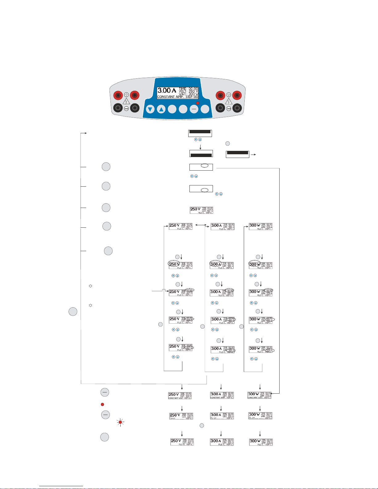
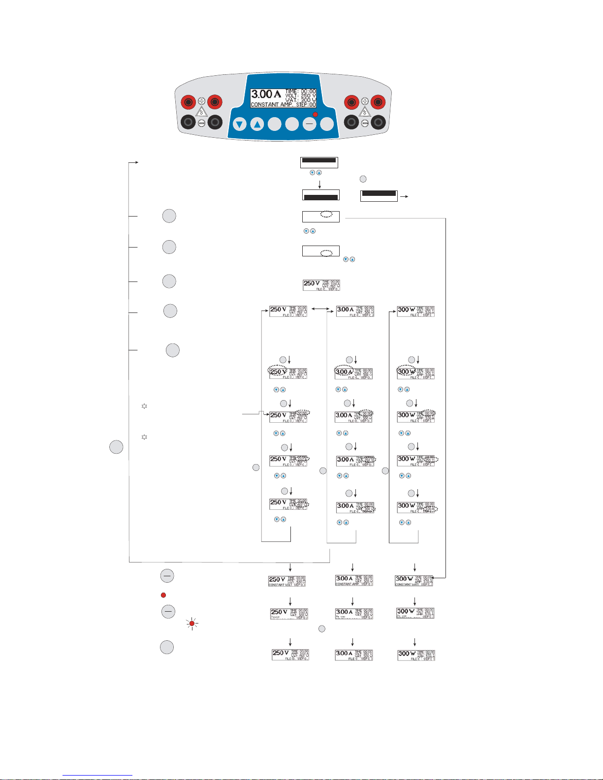
Flowchart
The flowchart below describes the various screens displayed on the 250V Power Supply and
the keys used to navigate through the screens.
1
Mode
Constant
START
PAUSE
STOP
Power Supply
3AP
1. Switch on Main Power Switch
5. Press to choose Constant
Volt or amperage
Constant
Choose constant
Volt, the Volt's word
size will be bigger
than other words.
Amp . & WAT . wil l be
"maxi value" and
Time will be "00:00".
Choose constant
Amp, the Amp's word
size will be bigger
than other words.
Volt. & WAT. will be
"maxi value" and
Time will be "00:00".
6. Press to choose Volt; Time;
Amp or Wat. which would like to adjust.
Mode
VoltBlinking, press
to increase
or decrease value
TIME Blinking, press
to increase
or decrease value
AMP Blinking, press
to increase
or decrease value
AMP Blinking, press
to increase
or decrease value
TIME Blinking, press
to increase
or decrease value
Volt Blinking, press
to increase
or decrease value
Mode
Press
Mode
Press
Mode
Press
Mode
Press
Mode
Pre ss to en te r Step 2
Mode
Press
Mode
Press
4. Press to star t power supply, the
parameters will stop blinking and LED
light on " "
START
PAUSE
Display "Constant Volt'
Display "Constant AMP'
5. Press again t o pause power supply,
the LED is flashing " "
START
PAUSE
Time can't on 0:00condition and the timer
should set 0:01 at least on each step.
On each step, the timer will count down till
time is up and then go to next step. Till all steps
have run complete, the power supply w ill sto p.
This stepcan press to changecondition. Process is same as step 4.
Mode
4. Press to stop power supply, the LED
will be off.
STOP
The parameters will be blinking 5 sec. After
5 sec., if you don't press any key, the
parameters will stop blinking and enter this
value to the power supply automatically.
Constant Mode
Program Mode
Press to choose constant mode
or program mode then press .
Mode
Constant Mode
Program Mode
Constant Mode
Program Mode
Instruction Procedure
is same as Mode 302,
but this mode can do
constant Watt.
2. Press to set or down load File.
Mode
File Blinking, press
to se t file #.
FILE# : 01
STEPS : 02
3. Press agai n to s et t ota l steps request.
Mode
STEPS Blinking, press
to set total steps request..
FILE# : 01
STEPS : 02
4. Press agai n to enter setting condition.
Mode
1
1
1 1 1
1
1 1
1
1
1
1
1
1
1
1
1
1
Wat. Blinking, press
to inc re ase
or decrease value
Mode
Press
1 1
Wat. Blinking, press
to increase
or decrease value
Mode
Press
1
1
Mode
Press to ente r Step 2
Pre ss more 3 sec., the display will reture to main page
Mode
1
1
1
11
11
Choose constant
Wat., the W's word
size will be bigger
than other words.
Volt. & Amp. will be
"maxi value" and
Time will be "0".
W Blinking, press
to increase
or decrease value
TIME Blinking, press
to increase
or decrease value
Volt Blinking, press
to increase
or decrease value
Mode
Press
Mode
Press
Mode
Press
Amp. Blinking, press
to increase
or decrease value
Mode
Press
1
1
1
1
1
1
1
1
1
1
Mode
Press to ente r Step 2
Display "Constant Watt"
1
1
1
1
Download fille and start the power supply
9
1
Mode
Constant
START
PAUSE
STOP
Power Supply
3AP
1. Switch on Main Power Switch
5. Press to choose Constant
Volt or amperage
Constant
Choose constant
Volt, the Volt's word
size will be bigger
than other words.
Amp . & WAT . wil l be
"maxi value" and
Time will be "00:00".
Choose constant
Amp, the Amp's word
size will be bigger
than other words.
Volt. & WAT. will be
"maxi value" and
Time will be "00:00".
6. Press to choose Volt; Time;
Amp or Wat. which would like to adjust.
Mode
VoltBlinking, press
to increase
or decrease value
TIME Blinking, press
to increase
or decrease value
AMP Blinking, press
to increase
or decrease value
AMP Blinking, press
to increase
or decrease value
TIME Blinking, press
to increase
or decrease value
Volt Blinking, press
to increase
or decrease value
Mode
Press
Mode
Press
Mode
Press
Mode
Press
Mode
Pre ss to en te r Step 2
Mode
Press
Mode
Press
4. Press to star t power supply, the
parameters will stop blinking and LED
light on " "
START
PAUSE
Display "Constant Volt'
Display "Constant AMP'
5. Press again t o pause power supply,
the LED is flashing " "
START
PAUSE
Time can't on 0:00condition and the timer
should set 0:01 at least on each step.
On each step, the timer will count down till
time is up and then go to next step. Till all steps
have run complete, the power supply w ill sto p.
This stepcan press to changecondition. Process is same as step 4.
Mode
4. Press to stop power supply, the LED
will be off.
STOP
The parameters will be blinking 5 sec. After
5 sec., if you don't press any key, the
parameters will stop blinking and enter this
value to the power supply automatically.
Constant Mode
Program Mode
Press to choose constant mode
or program mode then press .
Mode
Constant Mode
Program Mode
Constant Mode
Program Mode
Instruction Procedure
is same as Mode 302,
but this mode can do
constant Watt.
2. Press to set or down load File.
Mode
File Blinking, press
to se t file #.
FILE# : 01
STEPS : 02
3. Press agai n to s et t ota l steps request.
Mode
STEPS Blinking, press
to set total steps request..
FILE# : 01
STEPS : 02
4. Press agai n to enter setting condition.
Mode
1
1
1 1 1
1
1 1
1
1
1
1
1
1
1
1
1
1
Wat. Blinking, press
to inc re ase
or decrease value
Mode
Press
1 1
Wat. Blinking, press
to increase
or decrease value
Mode
Press
1
1
Mode
Press to ente r Step 2
Pre ss more 3 sec., the display will reture to main page
Mode
1
1
1
11
11
Choose constant
Wat., the W's word
size will be bigger
than other words.
Volt. & Amp. will be
"maxi value" and
Time will be "0".
W Blinking, press
to increase
or decrease value
TIME Blinking, press
to increase
or decrease value
Volt Blinking, press
to increase
or decrease value
Mode
Press
Mode
Press
Mode
Press
Amp. Blinking, press
to increase
or decrease value
Mode
Press
1
1
1
1
1
1
1
1
1
1
Mode
Press to ente r Step 2
Display "Constant Watt"
1
1
1
1
Download fille and start the power supply

10
Getting Started
Installing the 250V Power Supply
1. Check the label located near the AC inlet to ensure that the unit is compatible with locally
provided voltage.
2. Place the 250V Power Supply on a level laboratory bench. Keep the area around the power
supply clear to ensure proper ventilation of the unit.
3. For your safety: Position the unit properly such that the On-Off switch and the AC inlet
located on the rear of the unit are easily accessible.
4. Ensure the AC power switch is in the Off position.
5. Attach the power cord to the AC inlet. Use only properly grounded AC outlets and power
cords.
6. Connect the leads from the electrophoresis unit; insert the red lead (+) into the red output
jack, and the black lead (-) into the black output jack.
Important Guidelines
Introduction
The important guidelines for operating the 250V Power Supply are provided in this section. We
recommend that you carefully review these guidelines before operating the instrument.
Important
For best results, do NOT use the 250V Power Supply at its maximal electrical load limits.
Variations in buffer conditions can result in exceeding the power supply’s maximum voltage,
current, or power output capacity and produce undesirable variations in electrophoretic
separations.
General Operating Instructions
Follow the instructions below to operate the 250V Power Supply.
• Turn on the 250V Power Supply by toggling the power switch on the rear side of the
instrument. Upon start-up, the Display Screen appears on the screen.
• Use the START/PAUSE and STOP keys and output jacks for applications.
• Use the CONSTANT key to set up probable operation model for applications.
Recommendation
The duration of electrophoresis can be defined in time (hours/minutes). When using this or any
electrophoresis product, we recommend that you adhere to the protocols given in the

11
electrophoresis product manuals, and durations, specified in time.
Important
For best results, follow these important guidelines when running multiple gels and
electrophoresis units concurrently.
For example:
• Avoid running samples of widely differing salt concentrations or sample buffers at the same
time or on the same gel.
• Properly prepare and desalt your samples.
Note: Variations in conductivity due to differences in buffer salt concentrations can affect the run of all
the samples run at the same time.

12
Operational Modes
Introduction
The 250V Power Supply is designed to operate under two modes, Constant Voltage
Operation / Constant Current Operation or Programming Mode, depending upon your
electrophoresis needs.
Use the Constant Voltage / Current Operation for applications that require only one specific
voltage limit, current limit, and power limit continuously during the entire duration of
electrophoresis.
Display Screen
The Display Screen is the screen to appear after turning on the power to your instrument.
You can choose the operational Mode (Constant Operation or Constant Current Mode) on
the downward side of the display screen.
• On the Display Screen:
• The voltage value is displayed on the left-top side of the display screen.
• The Timer is the first line on the right-top, and current value is displayed in the second
line on the right-top side of the display screen.
Constant Operation Protocol
Introduction
Instructions for operating the 250V Power Supply in the Constant Operation are provided in
this section. The Constant Voltage / Current Mode allow you to specify a voltage limit, and
current limit to be used continuously during the entire duration of electrophoresis. Review the
guidelines provided in this manual before starting electrophoresis using the 250V Power
Supply.
A basic Constant Voltage / Current Mode operating procedure of the 250V Power Supply is
provided below. We recommend reading the guidelines provided in this manual for best results
before starting an operation.
1. Use the power switch on the rear side of the instrument to turn on the 250V Power Supply.
The Display Screen will appear on the screen.
2. Press the CONSTANT key to select either Constant Voltage Operation or Constant
Current Operation from the Display Screen.
3. Use the ▼▲ arrow keys to set either voltage (V) or current (mA) parameters to the
appropriate values.
4. Choose and use ▼▲ arrow key to set the time (hours/minutes) to specify the duration of the
electrophoresis.

13
4. Press START/PAUSE key to start electrophoresis.
5. Press the START/PAUSE key again to temporarily interrupt power to ongoing
electrophoresis without terminating the operation along with LED flashing.
6. Press the STOP key to stop electrophoresis.
7. To change Limits of Electrophoresis in Progress
• If you need to make changes to the current running limits, you must stop electrophoresis by
pressing the Mode key. Enter the changes and then press Start/Stop once again to restart
your operation.
Note: After stopping and restarting an operation, the timer resets to selected time and does not take into
account the time that electrophoresis was in progress before it was stopped.
Basic Programming Protocol
Introduction
Instructions for operating the 250V Power Supply in the Programming Operation are
provided in this section. The Programmable Mode allows you to vary levels in voltage (V),
current (mA), and power (W) during specified periods of time as discrete changes
(STEP) or as gradients (RAMP) for up to 10 Steps, depending upon your electrophoresis
needs.
A basic Programmable Mode operating procedure of the 250V Power Supply is provided
below. We recommend reading the guidelines provided in this manual for best results before
starting an operation.
Selecting a program
1. Select file mode by scrolling down using the ▼ key
2. When highlighted press Mode key
3. Select file number using the a▼▲ arrow keys
4. When file number is located press the Mode key
5. Select the number of steps by using the arrow ▼ ▲ arrow keys
6. To enter the parameters of the run press the Mode key
7. Select voltage Amperage or Watts use the Mode key
8. You can increase or decrease the value by using the▼▲ arrow keys
9. To set the time in hours press the Mode key
10. You can increase or decrease the value by using the▼▲ arrow keys
11. Select the Mode key again to select minutes.
12. You can increase or decrease the value by using the▼▲ arrow keys
13. To set the Amperage press the Mode key again
14. You can increase or decrease the value by using the▼▲ arrow keys

14
15. To set the Wattage, press the Mode key to select wattage.
16. You can increase or decrease the value by using the▼▲ arrow keys
17. To advance to the next step press the Mode key until the step is selected
18. Follow the above for each consecutive step.
Viewing a Program
1. Select the file number using the ▼▲ arrow keys when highlighted press the Mode
key.
2. Press the Mode key 3 more time to advance to the programming.
3. If multiple steps use the Mode key to advance through the program to the next step.
Editing a program
1. When in a file is selected the parameters can be edited by the Mode button
2. When the parameter is selected it will flash use the ▼▲ arrow keys to either
increase or decrease values.
3. Press the Mode key to migrate to the next parameter.
4. When the parameter is selected use the ▼▲ arrow keys to increase or decrease
the values.
Programs with multiple steps
1. When the parameters are complete a step in a file the program will proceed to the
next step. Follow the above editing procedure to edit the step within the program.
2. With the ▼▲ arrow keys select the Program Mode .
3. Select program number 1 through 10 then press the Mode key.
4. Select the number of segments 1 through 10 then press the Mode key.
5. Follow the basic programming protocol to set parameters.
Choosing Limiting Parameter Settings
Introduction
The 250V Power Supply is capable of operating at limiting voltage, or limiting
current. We recommend operating the 250V Power Supply at limiting voltage for most
applications. See below for more details.
Voltage Limiting
For most electrophoresis methods resistance increases throughout the run. Limiting the
voltage provides the following advantages:

15
• Current and power decrease throughout the run, providing an improving margin of safety
over time.
• The same voltage setting can be used regardless of the number or thickness of gels being
electrophoresed.
Current Limiting
Discontinuous buffer systems and, to a lesser extent, continuous systems increase resistance
during the run. If you use the current limiting setting on the 250V Power Supply, the voltage will
increase as resistance increases to satisfy Ohm’s law (V=IR). If no voltage limit is set and a
local fault condition occurs, such as a poor connection, very high local resistance may cause
the voltage to increase to the maximum capacity of the power supply. This may lead to local
overheating and damage to the electrophoresis cell or create unsafe conditions. When
operating under constant current conditions, set a voltage limit on the power supply at or
slightly above the maximum expected voltage.

16
Troubleshooting
Review the information in the table below to troubleshoot operating problems.
Problem Cause Solution
AC power cord is not
connected
Check AC power cord connections at both
ends. Use the correct cords.
The LCD screen
remains blank and
the fan does not run
when the power is
turned on
The fuse has blown Replace the fuse
Electrophoresis leads are
not connected to the power
supply or to the
electrophoresis unit(s), or
there is a broken circuit in
the electrophoresis cell
Check the connections to the power supply
and on your electrophoresis cell to make
sure the connection is intact; check condition
of wires in electrophoresis unit. Close the
circuit by reconnecting the cables. Press
START/PAUSE to restart the run.
High resistance due to tape
left on a pre-cast gel,
incorrect buffer
concentration, or incorrect
buffer volumes in the
electrophoresis cell
Correct the condition by making sure the
tape is removed from the pre-cast gel,
buffers are prepared
correctly, and the recommended volume of
buffer is added to the electrophoresis unit.
Operation stops
with alarm:
The screen displays
“NO LOAD”
High voltage application is
set to run on a very low
current
DISABLE No Load alarm on the
Display Screen
Operation stops
with alarm:
Display shows
“OVER VOLTAGE”
Circuit is interrupted
• Verify that the running buffer is correct.
• Verify the all cables are attached correctly
• Turn the Power switch off and on again;
restart application.
• If you cannot restart the
instrument, turn off the power, disconnect
the power cord from the outlet, and contact
Technical Service.
Operation stops
with alarm:
Display shows
“LEAKAGE”
Ground leak detected
during run
Check the electrophoresis system for
improper grounding. Restart the power
supply by turning the Power
switch off and on.

17
Operation stops
with alarm:
Display shows
“OVER TEMP”
Power supply is
overheating
• Turn off power supply. Check for sufficient
airflow around the power supply fan. After
cooling down, restart the power supply by
turning the Power switch to the on position.
• If you cannot restart the
instrument, turn off the power, disconnect
the power cord from the outlet, and contact
Technical Service.
Operational Electrical Parameters
Power Considerations
Electrophoresis is the migration of a charged particle under the influence of an electrical field.
The power supply output parameters voltage, current, and power
are related by the following two equations:
Voltage (V) = Current (I) x Resistance (R); (V=IR)
Power (W) = Current (I) x Voltage (V); (W=IV)
Resistance
Resistance of the assembled electrophoresis cell is dependent on the conductivity of the gel
buffer, the thickness of the gel, and the number of gels being run. Although the resistance is
determined by the gel system, the resistance can vary over the course of an electrophoretic
separation. For instance, in the Tris-Glycine buffer system, the fast moving, highly conductive
chloride ions in the gel are gradually replaced by the slower moving, less conductive glycine
ions from the running buffer as the gel runs. As a result, the resistance of the gel increases as
the chloride/glycine front moves down the gel, and the current decreases.
Voltage
The velocity with which an ion moves in an electric field will vary in proportion to the field
strength (volts per unit distance). The higher the voltage the faster an ion will move.
Current
Current is a function of the number of ions passing a given cross-section of the circuit at a
given time. For a given gel/buffer system, at a given temperature, current will vary in proportion
to the field strength (voltage) and/or crosssectional area (number and/or thickness of the gels).

18
Ions in solution and at a given voltage will move faster as the temperature increases,
increasing current.
Power
The power in Watts, or the rate of heat generated by the system, is directly proportional to
voltage and current (W=IV).
Repair and Maintenance of 250V Power Supply
Introduction
The 250V Power Supply requires no periodic maintenance program with the exception of an
occasional dry wipe-down of the instrument.
Encountering Problems
1. Check the troubleshooting section.
2. Call Technical Service.
3. If the unit must be shipped back for repair, contact Labnet International or the distributor for
a Return Authorization Number and shipping instructions. The unit will be repaired as
quickly as possible and returned to you.
Replacing the Fuse
For additional fuses, contact VWR International Technical Service.
To replace the fuse:
1. Turn off the main power switch at the rear of the 250V Power Supply and detach the power
cord from the rear of the 250V Power Supply.
2. Open the fuse compartment located inside the Power Entry Module by inserting a small flat
blade screwdriver into the slot below the ON/OFF switch. Turn the screwdriver to gently
pry open the fuse compartment.
Note: The fuse compartment will not open with the power cord in place.
3. Pull the fuse holder out of the compartment and inspect the fuse. If the fuse is burned or
there is a break in the fuse element, replace the fuse with an identical type of fuse (4A/250V)
as provided in the fuse holder (see figure below).
4. Place the fuse holder back into the compartment.
5. Snap the cover closed.

19
Technical Service
Web Resources
Visit the VWR’s website at www.vwr.com for:
• Complete technical service contact information.
• Access to VWR’s Online Catalog, and information about accessories and related products.
• Additional product information and special offers.
Contact Us For information or technical assistance contact your local VWR representative or
visit. www.vwr.com.
Legal Address of Manufacturer
United States Europe
VWR International VWR International Europe BVBA
1310 Goshen Parkway Haasrode Researchpark Zone 3
West Chester, PA 19380 Geldenaaksebaan 464
800-932-5000 B-3001 Leuven
http://www.vwr.com + 32 16 385011
http://www.be.vwr.com
Warranty
VWR International, Inc. warrants that this product will be free from defects in material and
workmanship for a period of two (2) years from date of purchase. If a defect is present, VWR
will, at its option, repair, replace, or refund the purchase price of this product at no charge to
you, provided it is returned during the warranty period. This warranty does not apply if the
product has been damaged by accident, abuse, misuse, or misapplication, or from ordinary
wear and tear.
For your protection, items being returned must be insured against possible damage or loss.
This warranty shall be limited to the replacement of defective products. IT IS EXPRESSLY
AGREED THAT THIS WARRANTY WILL BE IN LIEU OF ALL WARRANTIES OF FITNESS
AND IN LIEU OF THE WARRANTY OF MERCHANTABILITY.
For research use only. Not intended for any animal or human therapeutic or diagnostic use.

20
Equipment disposal
This equipment is marked with the crossed out wheeled bin symbol to indicate that this
equipment must not be disposed of with unsorted waste.
Instead it's your responsibility to correctly dispose of your equipment at lifecycle -end by
handling it over to an authorized facility for separate collection and recycling. It's also your
responsibility to decontaminate the equipment in case of biological, chemical and/or
radiological contamination, so as to protect from health hazards the persons involved in the
disposal and recycling of the equipment.
For more information about where you can drop off your waste of equipment, please contact
your local dealer from whom you originally purchased this equipment.
By doing so, you will help to conserve natural and environmental resources and you will
ensure that your equipment is recycled in a manner that protects human health.
Thank you.

21
Betriebsanleitung
VWR® Power Source
TM
250-V-Elektrophoresenetzteil
Hochstrom-Netzteil für
SDS-PAGE- und
DNA/RNA-Elektrophorese-Anwendungen
Artikelnummer Nordamerika
US-Kabel: 93000-746
Bestellnummern Europa:
EU-Kabel: 700-0115
GB-Kabel: 700-0116
CH-Kabel: 700-0117
Copyright Mai 2007 VWR Version Nr. 1

22
Inhaltsverzeichnis
FCC-Warnung 23
Sicherheitshinweise 23
Verpackungsinhalt 24
Produktspezifikationen 25
Übersicht 26
Beschreibung der Tasten und Schalter 27
Inbetriebnahme 27
Wichtige Anweisungen 28
Betrieb 29
Einstellen der Grenzparameter 32
Problembehebung 33
Elektrische Betriebsparameter 35
Reparatur und Wartung des 250-V-Netzteils 36
Technischer Kundendienst 37
Garantie 37
Geräteentsorgung 38

23
Warnung
Hinweis der Federal Communications Commission (USA)
Dieses Gerät wurde geprüft und hält die Grenzwerte für digitale Geräte der Klasse A gemäß
Teil 15 der FCC-Vorschriften ein. Diese Grenzwerte sollen einen ausreichenden Schutz vor
Störstrahlung gewährleisten, wenn das Gerät gewerblich genutzt wird. Dieses Gerät erzeugt
und verwendet Funkwellen und kann diese ausstrahlen. Bei unsachgemäßer Installation und
Verwendung kann es andere Funkverbindungen stören. Der Betrieb dieses Geräts in
Wohngebieten kann Störstrahlungen verursachen. In diesem Fall muss der Benutzer auf
eigene Kosten geeignete Maßnahmen zur Beseitigung der Störstrahlungen ergreifen. Durch
Veränderungen, die nicht ausdrücklich von der für die Konformität verantwortlichen Beteiligten
genehmigt wurden, kann die Befugnis des Benutzers zur Verwendung des Geräts erlöschen.
Sicherheitshinweise
Vermeiden von elektrischen Schlägen
Das Power Source 250-V-Netzteil erreicht eine Ausgangsspannung von max. 3 A oder
250 Volt , die gegen Erde elektrisch isoliert ist, um die Gefahr von elektrischen Schlägen für
den Benutzer zu verringern. Beachten Sie die folgenden Anweisungen, um einen sicheren
Betrieb des Geräts zu gewährleisten.
Das Power Source 250-V-
Netzteil ist für die Verwendung mit Elektrophoresekammern mit
abgeschirmten Bananensteckern konzipiert, sodass die Gefahr elektrischer Schläge für den
Benutzer verringert wird. VWR rät von der Verwendung von nicht abgeschirmten
Bananensteckern ab.
So vermeiden Sie elektrische Schläge:
1. Schließen Sie NIEMALS Kabel an die Ausgangsbuchsen an und trennen Sie NIEMALS
Kabel von den Ausgangsbuchsen, wenn die rote Leuchte über der Start/Stopp-Taste leuchtet
oder auf dem Bildschirm RUNNING (in Betrieb) angezeigt wird.
2. WARTEN Sie nach dem Stoppen eines Laufs mindestens 5 Sekunden, bevor Sie
Ausgangskabel oder angeschlossene Geräte anfassen.
3. Stellen Sie IMMER sicher, dass Hände, Arbeitsbereich und Geräte sauber und trocken
sind, bevor Sie Kabel anschließen oder das Netzgerät einschalten.
4. Schließen Sie das Netzgerät NUR an eine ordnungsgemäß geerdete
Wechselstromsteckdose an.

24
Vermeidung von Schäden am Gerät
1. Für eine ausreichende Belüftung des Geräts müssen nach hinten mindestens 10 cm und zu
beiden Seiten mindestens 5 cm Platz bleiben.
2. Betreiben Sie das Netzgerät nicht in Umgebungen, in denen eine hohe Luftfeuchtigkeit
(> 95 %) herrscht oder Kondensation auftreten kann.
3. Um nach dem Betrieb des Netzgerätes in einem kalten Raum Kondensation zu verhindern,
wickeln Sie das Gerät in einen Plastikbeutel, und bringen Sie das Gerät mindestens 2 Stunden
lang auf die neue Raumtemperatur, bevor Sie es aus dem Beutel nehmen und verwenden.
Symbole
Kennzeichnet am 250-V-Netzteil Bereiche, in denen die Gefahr eines
elektrischen Schlags besteht.
Lieferumfang
Produktkomponenten
Diese Bedienungsanleitung wird mit den folgenden Produkten geliefert:
Power Source 250-V-Netzteil (115/230 VAC, umschaltbar, 50/60 Hz)
Lieferumfang
Anzahl der Teile
250-V-Netzteil je 1
Gebrauchsanleitung 1
Ersatzsicherung je 1
Netzkabel 1
Garantiekarte 1
Nach Erhalt des Geräts
Überprüfen Sie das Gerät sorgfältig auf Transportschäden. Melden Sie jegliche Schäden dem
Spediteur; heben Sie die gelieferte Packung für spätere Kontrollen auf. Transportschäden
fallen nicht unter die Garantie.
Betreiben Sie das 250-V-Netzgerät immer gemäß den Anweisungen des
Herstellers, um einen sicheren und zuverlässigen Betrieb des Geräts
sicherzustellen. Tragen Sie bei der Arbeit im Labor grundsätzlich Handschuhe
und eine Schutzbrille.

25
Produktspezifikationen
Spezifikationen zum 250-V-Netzteil
Leistungsaufnahme (umschaltbar) 115 VAC, 50-60 Hz
230 VAC, 50-60 Hz
Sicherungen 1x 4 A/250 V, 1 Ersatzsicherung im Lieferumfang enth.
Max. Ausgangsleistung 300 Watt
Ausgangsspannungsbereich 5~250V
Ausgangsstromstärke 10 mA~3 A
Zeitschaltuhr ~99,99 pro Schritt
Ausgangsbuchsenpaare 4: 4 positiv, 4 negativ
Betriebsarten
Konstantspannung 1-V-Schritte
Konstantstrom 1-mA-Schritte
Konstantleistung 1-Watt-Schritte
Umschaltung Automatisch
Displaytyp Grafik-LCD
Displayabmessungen 53,64x15,64 mm (BxH)
Pausenfunktion Ja
Sicherheitsfunktion Erkennung: keine Ladung
Erkennung: Ladungsänderung
Überlastungserkennung
Kriechstrom
Automatischer Neustart
Programmierbar Ja
Anzahl speicherbarer Programme: 10
Programm: bis zu 10 Schritte
Stapelbar Ja
Gehäusematerial Flammhemmender ABS-Kunststoff
Gehäuseabmessungen 200x290x70 mm (BxTxH)
Betriebstemperatur 0-40 °C
Betriebsumgebung 100 % relative Luftfeuchtigkeit, 75-106 KPa,
maximal 2000 m ü. NN
Gewicht 2,6 kg
Zertifizierungen CE; TÜV; CUL
Garantie 2 Jahre

26
Einführung
Übersicht
Das Power Source 250-V-Netzgerät ist ein mikroprozessorgesteuertes Netzgerät, das die
meisten für die Elektrophorese benötigten Funktionen in einem benutzerfreundlichen Gerät
vereint. Dank der kleinen Stellfläche und der Stapelfunktion wird wertvoller Platz auf der
Arbeitsfläche gespart. Das Netzteil eignet sich für Anwendungen mit Konstantspannung,
-strom oder -leistung und bietet zusätzlich einen Programmierungsmodus. Das Gerät ist ideal f
ür DNA/RNA-Elektrophorese, SDS-PAGE, Nativ-PAGE sowie IEF-Anwendungen. Mit vier
gleichzeitig zu verwendenden Ausgangsbuchsenpaaren erlaubt das 250-V-Netzteil
Anwendungen mit höchster Leistung und Effizienz. Das Netzteil bietet drei Betriebsmodi:
Konstantspannung, Konstantstrom und Konstantleistung. Diese Gebrauchsanleitung
beschreibt die Inbetriebnahme und Bedienung des 250-V-Netzteils und umfasst wichtige
Hinweise zur Sicherheit und Wartung des Geräts.
Merkmale des Power Source 250-V-Netzgeräts
Die wichtigsten Merkmale des 250-V-Netzgeräts:
• Konstante Einstellung von Spannung, Leistung und Stromstärke
• Versorgung mehrerer Elektrophoresesysteme
• Großes LCD-Display mit klarer Menüführung erleichtert die Bedienung
• Programmierbarkeit für begrenzte Spannung (V), Stromstärke (mA) und Leistung (W).
• Ausgangsklemmen (vier Sets)
• Einstellung der Laufzeiten nach Zeit oder in Voltstunden
Zweck dieser Anleitung
Diese Bedienungsanleitung enthält folgende Informationen:
• Sicherheitshinweise
• Anweisungen zur Inbetriebnahme des Geräts
• Bedienungsanweisungen.
• Hinweise zur Reparatur und Wartung
Beachten Sie beim Betrieb des 250-V-Netzteils die in dieser Anleitung enthaltenen
Empfehlungen und Hinweise, um Ihre Sicherheit, beste Ergebnisse und optimale Leistung zu
gewährleisten.

27
Bezeichnung
Bedientasten
Taste Funktion
STOP: Startet den Betrieb über das Fenster Running.
START/PAUSE: Startet den Betrieb, unterbricht bei laufenden Vorgängen vorü
bergehend die Stromzufuhr, ohne die Elektrophorese zu beenden, und stellt nach
der Unterbrechung die Stromzufuhr ohne Zurücksetzen des Timers wieder her.
CONSTANT (Konstant): Stellt die Werte für Konstantspannung oder -strom ein.
MODE (Betriebsmodus): Stellt den Betriebsmodus Konstantspannung,
Konstantleistung oder Konstantstrom ein.
Abwärtspfeil: Bewegt den Cursor zwischen Parametern nach unten und
verringert numerische Werte.
Aufwärtspfeil: Bewegt den Cursor zwischen Parametern nach oben und erhöht
numerische Werte.
Inbetriebnahme
Installation des 250-V-Netzteils
1. Überprüfen Sie die Angaben auf dem Etikett am Netzeingang, um sich zu vergewissern,
dass das Gerät für die örtliche Netzspannung geeignet ist.
2. Stellen Sie das 250-V-Netzteil auf eine ebene Laborarbeitsfläche. Lassen Sie um das
Netzgerät herum Platz, um eine ausreichende Belüftung des Geräts sicherzustellen.
3. Zu Ihrer Sicherheit: Stellen Sie das Gerät so auf, dass der Netzschalter und der
Netzeingang an der Rückseite problemlos zugänglich sind.
4. Vergewissern Sie sich, dass der Netzschalter sich in der Position Off (Aus) befindet.
5. Schließen Sie das Netzkabel an den Netzeingang an. Verwenden Sie ausschließlich
ordnungsgemäß geerdete Steckdosen und Netzkabel.

28
6. Schließen Sie die Kabel des Elektrophoresegeräts an: Stecken Sie das rote Kabel (+) in die
rote Ausgangsbuchse und das schwarze Kabel (-) in die schwarze Ausgangsbuchse.
Wichtige Anweisungen
Einführung
Dieser Abschnitt enthält wichtige Hinweise zum Betrieb des 250-V-Netzteils. Lesen Sie die
Anweisungen sorgfältig, bevor Sie das Gerät bedienen.
Wichtig
Betreiben Sie das 250-V-Netzteil NICHT an den maximalen elektrischen Belastungsgrenzen.
Schwankungen der Pufferbedingungen können dazu führen, dass die maximalen Werte der
Spannungs-, Strom- oder Ausgangsleistung des Netzteils überschritten werden und es zu
unerwünschten Schwankungen bei den elektrophoretischen Trennungen kommt.
Allgemeine Bedienungsanweisungen
Befolgen Sie zur Bedienung des 250-V-Netzteils die folgenden Anweisungen.
• Schalten Sie das 250-V-Netzteil über den Netzschalter auf der Geräterückseite ein. Beim
Start wird auf dem Display die Einstellung der Stromstärke angezeigt.
• Verwenden Sie entsprechend der Anwendung die START/PAUSE- und STOP-Taste sowie
die Ausgangsbuchsen.
• Verwenden Sie die Taste CONSTANT (Konstant), um den Betriebsmodus einzustellen.
Empfehlung
Die Dauer der Elektrophorese kann als Zeit (Stunden/Minuten) definiert werden. Es wird
empfohlen, bei der Verwendung dieses oder eines anderen Elektrophoreseprodukts die
Protokolle und Zeitangaben einzuhalten, die in der Anleitung des jeweiligen Produkts
beschrieben sind.
Wichtig
Beachten Sie die folgenden wichtigen Hinweise, wenn Sie mehrere Gele und
Elektrophoresegeräte gleichzeitig verwenden.
Zum Beispiel:
• Vermeiden Sie es, Proben mit sehr unterschiedlichen Salzkonzentrationen oder sehr
unterschiedlichen Probenpuffern gleichzeitig oder auf dem gleichen Gel zu verarbeiten.
• Bereiten Sie Ihre Proben ordnungsgemäß vor, und entsalzen Sie sie.

29
Hinweis: Schwankungen der Leitfähigkeit aufgrund unterschiedlicher Puffersalzkonzentrationen können
sich auf alle gleichzeitig verarbeiteten Proben auswirken.
Betriebsmodi
Einführung
Das 250-V-Netzteil kann je nach Ihren Elektrophorese-Anforderungen in verschiedenen Modi
betrieben werden: im Konstant-Modus oder im Programmierungsmodus.
Die Modi Konstantspannung, Konstantleistung oder Konstantstrom eignen sich für
Anwendungen, bei denen während der gesamten Elektrophorese durchgehend ein
bestimmter Grenzwert für die Spannung, Stromstärke oder Leistung eingehalten werden
muss.
Einschalten
Verwenden Sie beim Einschalten die ▼▲-Pfeiltaste, um den gewünschten Betriebsmodus
auszuwählen (Konstant- oder Programmierungsmodus), und drücken Sie anschließend
Mode (Betriebsmodus) um die Auswahl zu bestätigen.
• Auf dem Display:
• Der Sollwert (Volt, Ampere oder Watt) wird oben links auf dem Display angezeigt.
• In der ersten Zeile rechts oben befindet sich die Zeitschaltuhr, und die anderen Werte
(Volt, Ampere oder Watt) werden in der zweiten und dritten Zeile rechts auf dem
Display dargestellt.
Protokoll für den Konstantbetrieb
Einführung
Dieser Abschnitt beschreibt die Funktionsweise des 250-V-Netzteils im Konstantbetrieb. Im
Modus mit konstanter Spannung, Stromstärke oder Leistung kann der Anwender einen
Grenzwert für die Spannung, Stromstärke oder Leistung festlegen, der während der gesamten
Elektrophorese verwendet wird. Lesen Sie sich die in dieser Anleitung enthaltenen Hinweise
durch, bevor Sie das 250-V-Netzteil für Elektrophorese-Anwendungen in Betrieb nehmen.
Das grundlegende Betriebsverfahren für die Modi Konsta ntspannung, Konstantstrom oder
Konstantleistung des 250-V-Netzteils wird weiter unten beschrieben. Es wird empfohlen, vor
dem Starten eines Verfahrens die Hinweise in dieser Gebrauchsanleitung zu lesen, um
optimale Ergebnisse zu erzielen.
1. Schalten Sie das 250-V-Netzteil mit dem Netzschalter an der Geräterückseite ein. Auf dem
Display wird der Konstant- und Programmierungsmodus angezeigt.
2. Wenn der Konstant-Modus markiert ist, drücken sie die Taste Mode (Betriebsmodus).
3. Mit der Taste Mode bewegen Sie sich zum gewünschten Parameter (Volt, Ampere oder

30
Watt).
4. Drücken
Sie die Taste CONSTANT (Konstant), um auf dem Display einen der
Betriebsmodi Konstantspannung, Konstantstrom oder Konstantleistung
auszuwählen
.
5.Verwenden Sie die ▼▲-Pfeiltasten, um entweder die Spannung (VOLT), die Stromstärke
(AMP) oder die Leistung (WAT) auf den gewünschten Wert einzustellen.
6. Verwenden Sie zum Einstellen der ZEIT die Taste Mode (Betriebsmodus), und betätigen
Sie eine der ▼▲-Pfeiltasten, um die Dauer der Elektrophorese in Stunden und Minuten
einzustellen.
7. Drücken Sie die Taste START/PAUSE, um die Elektrophorese zu starten.
8. Drücken Sie die Taste START/PAUSE erneut, um die laufende Elektrophorese kurz zu
unterbrechen, ohne den Durchlauf zu beenden. Dabei blinkt die LED-Anzeige.
9. Zum Abbrechen der Elektrophorese drücken Sie die STOP-Taste.
10. Wenn während des Durchlaufs Parameter geändert werden müssen, stoppen Sie die
Elektrophorese, indem Sie die Taste Mode
(Betriebsmodus) drücken. Nehmen Sie die gew
ünschten Änderungen vor, und drücken Sie erneut auf Start/Stop, um den Vorgang wieder
aufzunehmen.
Hinweis: Beim Stoppen und Neustarten eines Vorgangs wird die Zeitschaltuhr auf die angewählte Zeit
zurückgesetzt, sodass die Dauer der Elektrophorese vor dem Stoppen nicht berücksichtigt wird.
Grundlegendes Protokoll für den Programmierungsmodus
Einführung
Dieser Abschnitt beschreibt die Funktionsweise des 250-V-Netzteils im
Programmierungsmodus.Mit dem Programmierungsmodus können Sie entsprechend
Ihrer Elektrophorese-Anforderungen einzelne Programmschritte (STEPS) planen, bei denen
zu bestimmten Zeiten die Werte für Spannung (V), Stromstärke (mA) und Leistung (W)
geändert werden. Insgesamt können 10 Schritte programmiert werden.
Das grundlegende Funktionsprinzip
des 250-V-Netzteils im Programmierungsmodus wird
weiter unten beschrieben. Es wird empfohlen, vor dem Starten eines Verfahrens die
Hinweise in dieser Gebrauchsanleitung zu lesen, um optimale Ergebnisse zu erzielen.
Auswahl eines Programms
19. Verwenden Sie die
▼-Taste, um nach unten zu navigieren und den
Programmierungsmodus anzuwählen.
20. Wenn dieser markiert ist, drücken Sie die Taste Mode (Betriebsmodus).
21. Wählen Sie mithilfe der ▼▲-Pfeil-Tasten die Dateinummer.
22. Nach Anwahl der gewünschten Programmnummer, drücken Sie die Taste Mode
 Loading...