

VWR International 1917, 1927 Installation And Operation Manual

Sheldon Manufacturing Inc. P.O. Box 627 Cornelius, Oregon 97113
EMAIL: tech@Shellab.com
1-800-322-4897 (503) 640-3000 FAX (503) 640-1366
REACH-IN DRY CO2
INCUBATOR
M
ODEL: 1917 & 1927
INSTALLATION AND OPERATION MANUAL
INTERNET: http://www.Shellab.com/~Shellab

TABLE OF CONTENTS
SECTION 1.0 RECEIVING AND INSPECTION
SECTION 2.0 GRAPHIC SYMBOLS
SECTION 3.0 INSTALLATION
SECTION 4.0 CONTROL PANEL OVERVIEW
SECTION 5.0 OPERATION
SECTION 6.0 FYRITE READING
SECTION 7.0 MAINTENANCE
SECTION 8.0 TROUBLESHOOTING
SECTION 9.0 PARTS LIST
UNIT SPECIFICATION
SCHEMATICS
REV 6/04
4861495
This unit is a CO2 incubator for professional, industrial or educational use where the
preparation or testing of materials is done at approximately atmospheric pressure and no
flammable, volatile or combustible materials are being heated. These units are not
intended for hazardous or household locations or use.
2

Section
1
RECEIVING AND INSPECTION
IMPORTANT: READ THIS INSTRUCTION MANUAL IMMEDIATELY.
Your satisfaction and safety require a complete understanding of this unit, including
its proper function and operational characteristics. Be sure operators are given
adequate training before attempting to put the unit in service. NOTE: This
equipment must be used for its intended application; any alterations or
modifications will void your warranty.
1.1 Inspection: The carrier, when accepting shipment, also accepts responsibility for
safe delivery and is liable for loss or damage claims. On delivery, inspect for
visible exterior damage, note and describe on the freight bill any damage found
and enter your claim on the form supplied by the carrier.
1.2 Inspect for concealed loss or damage on the unit itself, both interior and exterior. If
any the carrier will arrange for official inspection to substantiate your claim. Save
the shipping crate until you are sure the unit has been delivered in good condition.
1.3 Return Shipment: If for any reason you must return the unit, contact your
customer service representative for return authorization and supply data plate
information. Please see the manual cover for information on where to reach
customer service.
1.4 Make sure that all of the equipment indicated on the packing slip is included with
the unit. Carefully check all packaging before discarding. This unit is equipped
with 6 shelves, 24 shelf clips, CO2 tubing kit and 4 adjustable feet.
3
Section
2
GRAPHIC SYMBOLS
Your incubator has been provided with a display of graphic symbols on the control panel
which is designed to help in identifying the use and function of the available user adjustable
components.
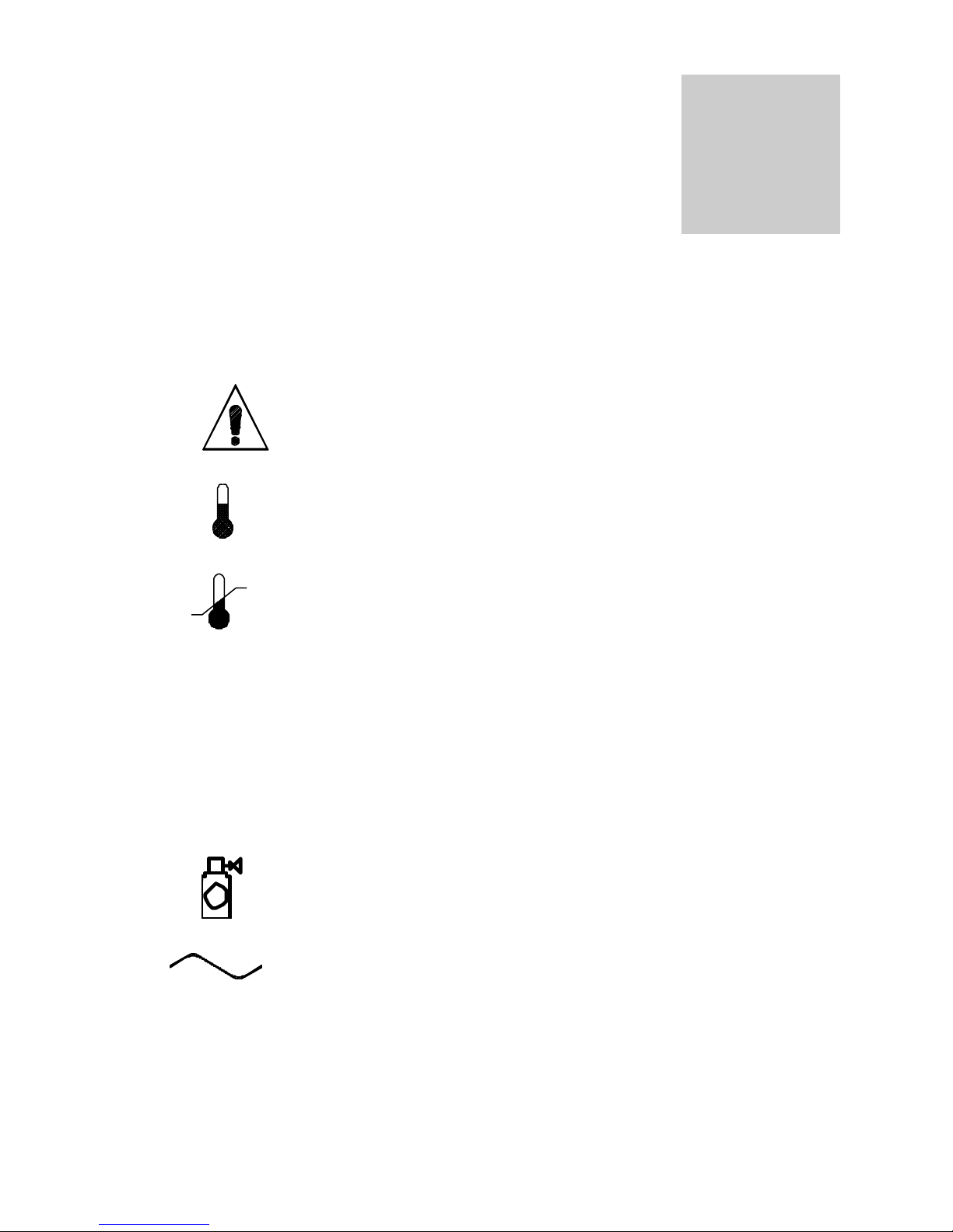
2.1 Indicates that you should consult your manual for further
description or discussion of a control or user item.
2.2 Indicates "Temperature"
2.3 Indicates "Over-Temperature Safety".
2.4
C° Indicates "Degrees Centigrade".
2.5 CO2 Indicates "Carbon Dioxide".
2.6 Indicates "Gas" (CO2 for this unit.)
2.7 Indicates "AC Power On".
4

Section
3
INSTALLATION
Local city, county or other ordinances may govern the use of this equipment. If you have
any questions about local requirements, please contact the appropriate local agency.
Installation may be performed by the end user. It is unnecessary for this unit to be installed
by a technician.
Under normal circumstances this unit is intended for use indoors, at room temperatures
between 5° and 40°C, at no greater than 80% Relative Humidity (at 25°C) and with a
supply voltage that does not vary by more than 10%. Customer service should be
contacted for operating conditions outside of these limits.
3.1 Power Source: The power supply must be properly grounded (earthed) and
correctly sized to match the unit data plate rating. VOLTAGE SHOULD NOT
VARY MORE THAN 10% FROM THE DATA PLATE RATING. These units are
intended for a 50/60 Hz application. If supplied with a detachable cord set, plug
the female end into the inlet on the unit and the male plug into the supply. Assure
that units requiring a fuse have a fuse installed. This fuse may be at the inlet or
part of the cord set male plug. Note that electrical supply to the unit must conform
to all national and local electrical codes.
3.2 Location: When selecting a site for the unit, consider conditions which may affect
performance, such as heat from steam radiators, ovens, autoclaves, etc. Avoid
direct sun, fast-moving air currents, heating/cooling ducts, and high-traffic areas.
To ensure air circulation around the unit, allow a minimum of 5cm of clearance
between the incubator and surrounding walls, or partitions which might obstruct
free air flow.
3.3 Lifting/Handling: These units are heavy and care should be taken to use
appropriate lifting devices that are sufficiently rated for these loads. Units should
only be lifted from their bottom surfaces. Doors, handles and knobs are not
adequate for lifting or stabilization. The unit should be completely restrained from
tipping during lifting or transport. All moving parts, such as shelves and trays
should be removed and doors need to be positively locked in the closed position
during transfer to prevent shifting and damage.
3.4 Leveling: The unit must sit level and solidly. Leveling feet are supplied and
should be installed in the four holes in the bottom corners of the unit. With the feet
installed and the unit standing upright, each foot can be raised by turning it in a
counterclockwise direction. An opposite clockwise rotation will lower that foot.
Adjust the foot at each corner until the unit stands level and solid without rocking.
5

3.5 Cleaning: The unit chamber should be cleaned and sterilized prior to operating.
Use a suitable disinfectant that is appropriate to your application. DO NOT USE
chlorine-based bleaches or abrasives as this will damage the interior chamber.
DO NOT USE spray cleaners that might leak through openings and cracks and
get on electrical parts or that may contain solvents that will harm the coatings.
Special care should be taken when cleaning around sensors to prevent damage.
Warning: Never clean the unit with alcohol or flammable cleaners with the unit
connected to the electrical supply. Always disconnect the unit from the electrical
service when cleaning and assure all volatile or flammable cleaners are
evaporated and dry before reattaching the unit to the power supply.
3.6 Shelves and Interior Parts: Shelving and clips are supplied with the unit. See
Figure 1.
6

Figure 1
7

Section
4
CONTROL PANEL OVERVIEW (See Figure 2)
4.1 Power Switch: The main power I/O (On/Off) switch on the panel controls all the
power to the incubator. It must be in the I/On position before any systems are
operational.
4.2 Main Temperature Controller: Marked C°, this controller contains the digital
temperature display, UP and DOWN arrow pads, HIGH and LOW alarm indicators
and an alarm MUTE indicator.
A. Digital Temperature Display indicates the actual temperature within the
chamber to .1°C.
B. UP and DOWN Arrow Pads are used for inputting the set point, calibrating
the display and muting or unmuting the audible alarm.
C. HIGH and LOW Alarm Indicators will light whenever there is an alarm
condition associated with the temperature within the incubator.
D. Alarm MUTE Indicator will light whenever the audible alarm has been muted.
4.3 Heating: This pilot lamp is on whenever the temperature controller is energizing
the heating element. The element will go on and off as heat is needed to maintain
the set point temperature.
4.4 High Limit Thermostat: Marked SET HIGH LIMIT, the High Limit Thermostat is
completely independent of the Main Temperature Controller and functions as an
override control. If at any time the Main Temperature Control fails in the ON
position, the chamber temperature is then limited to the High Limit Thermostat set
point which is manually set approximately 1°C above the Main Controllers set
point. Note that the HEATING indicator will continue to function under the control
of the High Limit Thermostat. It is not recommended that the unit be allowed to
operate for an extended period of time using the High Limit to control temperature
as temperature uniformity will suffer.
4.5 Safety Activated: This pilot lamp is on whenever the High Limit Thermostat has
taken control of the incubator and shut down the elements. Under normal
operating conditions this pilot lamp should never be on.
8
 Loading...