

VWR International 1915, 1925 Installation And Operational Manual

REACH-IN INCUBATOR
MODEL: 1915/1925
INSTALLATION AND OPERATIONAL MANUAL
Sheldon Manufacturing Inc. P.O. Box 627 Cornelius, Oregon 97113
EMAIL: tech@Shellab.com INTERNET: http://www.Shellab.com/~Shellab
1-800-322-4897 (503) 640-3000 FAX (503) 640-1366
10/12
4861401

TABLE OF CONTENTS
SECTION 1.0 RECEIVING AND INSPECTION
SECTION 2.0 INSTALLATION
SECTION 3.0 GRAPHIC SYMBOLS
SECTION 4.0 CONTROL OVERVIEW
SECTION 5.0 OPERATION
SECTION 6.0 CHART RECORDER INSTALLATION
SECTION 7.0 MAINTENANCE
SECTION 8.0 TROUBLESHOOTING
SECTION 9.0 PARTS LIST
UNIT SPECIFICATIONS
SCHEMATICS
These units are general purpose incubators for professional, industrial or educational
use where the preparation or testing of materials is done at approximately atmospheric
pressure and no flammable, volatile or combustible materials are being heated. These
units are not intended for hazardous or household locations or use.

RECEIVING AND INSPECTION
Section
Your satisfaction and safety require a complete understanding of this unit. Read
the instructions thoroughly and be sure all operators are given adequate training
before attempting to put the unit in service. NOTE: This equipment must be used
only for its intended application; any alterations or modifications will VOID your
warranty.
1.1 Inspection: The carrier, when accepting shipment, also accepts responsibility
for safe delivery and is liable for loss or damage. On delivery, inspect for visible
exterior damage, note and describe on the freight bill any damage found, and
enter your claim on the form supplied by the carrier.
1.2 Inspect for concealed loss or damage on the unit itself, both interior and exterior.
If necessary, the carrier will arrange for official inspection to substantiate your
claim.
1.3 Return Shipment: Save the shipping crate until you are sure all is well. If for
any reason you must return the unit, first contact your customer representative
for authorization. Supply nameplate data, including model number and serial
number. Please see the manual cover for information on where to contact
customer service.
1.4 Accessories: Verify that all of the equipment indicated on the packing slip is
included with the unit. Carefully check all packaging before discarding. These
units are equipped with 6 shelves, 24 shelf clips and 4 leveling feet.

INSTALLATION
Section
Local city, county or other ordinances may govern the use of this equipment. If you have any questions
about local requirements, please contact the appropriate local agency. Installation may be performed by
the end user.
Under normal circumstances this unit is intended for use indoors, at room temperatures between 5 and
40C, at no greater than 80% Relative Humidity (at 25C) and with a supply voltage that does not vary by
more than 10%. Customer service should be contacted for operating conditions outside of these limits.
2.1 Power Source: The electrical supply circuit to the incubator must conform to all national and
local electrical codes. Consult the incubator’s serial data plate for the voltage and ampere
requirements before making connection. VOLTAGE SHOULD NOT VARY MORE THAN 10%
FROM THE SERIAL PLATE RATING. This unit is intended for 50/60 Hz application. A separate
circuit is recommended to prevent possible loss of product due to overloading or failure of other
equipment on the same circuit.
2.2 Location: When selecting a site for the incubator, consider all conditions which may affect
performance, such as extreme heat from steam radiators, stoves, ovens autoclaves, etc. Avoid
direct sun, fast-moving air currents, heating/cooling ducts, and high traffic areas. To ensure air
circulation around the unit allow a minimum of 10cm between the unit and any walls or partitions
which might obstruct free airflow.
2.3 Lifting / Handling: These units are heavy and care should be taken to use appropriate lifting
devices that are sufficiently rated for these loads. Units should only be lifted from their bottom
surfaces. Doors, handles and knobs are not adequate for lifting or stabilization. The unit should
be completely restrained from tipping during lifting or transport. All moving parts, such as shelves
and trays should be removed and doors need to be positively locked in the closed position during
transfer to prevent shifting and damage.
2.4 Leveling: The unit must sit level and solidly. Leveling feet (supplied) are to be installed in the
2.5 Cleaning: The incubator was cleaned at the factory, but not sterilized. Remove all interior parts,
holes at the base of the incubator. Turn the leveling feet counterclockwise to raise level. If the
unit must be moved, turn the leveling feet in all the way to prevent bending of the feet.
including shelves and shelf clips and clean all parts and the chamber with a disinfectant that is
appropriate for your application. A thorough periodic cleaning is strongly recommended.
WARNING: Never clean the unit with alcohol or flammable cleaners with the unit connected to the
electrical supply. Always disconnect the unit from the electrical service when cleaning and assure
all volatile or flammable cleaners are evaporated and dry before reattaching the unit to the power
supply.
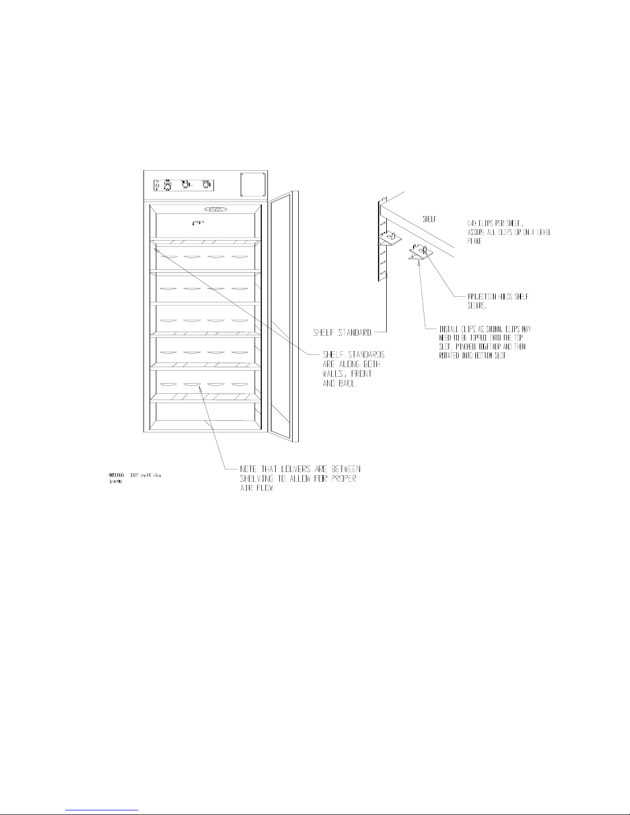
2.6 Place shelves into chamber at desired position. See Figure 1.
Figure 1
GRAPHIC SYMBOLS
Section
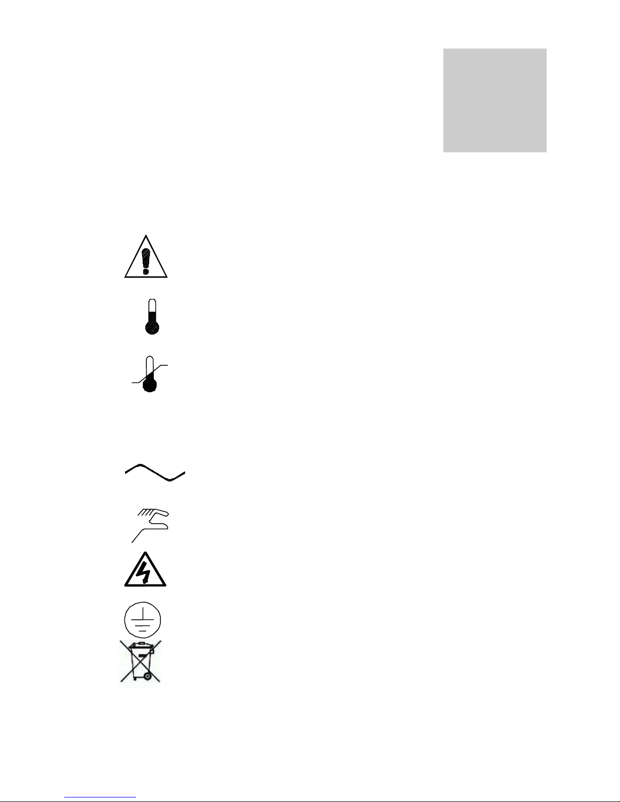
Your incubator is provided with a display of graphic symbols on the control panel which
are designed to help identify the use and function of the adjustable components.
1. Indicates that you should consult your manual for further
description and discussion of a control or user item.
2. Indicates “Temperature”
3. Indicates “Overtemperature”
4. C Indicates “Degrees Centigrade”
5. Indicates “AC Power”
6. Indicates “Manual Adjustment”
7. Indicates “Potential Shock Hazard” behind partition
8. Indicates “Earth Ground”
9. Indicates “Unit should be recycled” (Not disposed of in
land-fill)
CONTROL PANEL OVERVIEW
Section
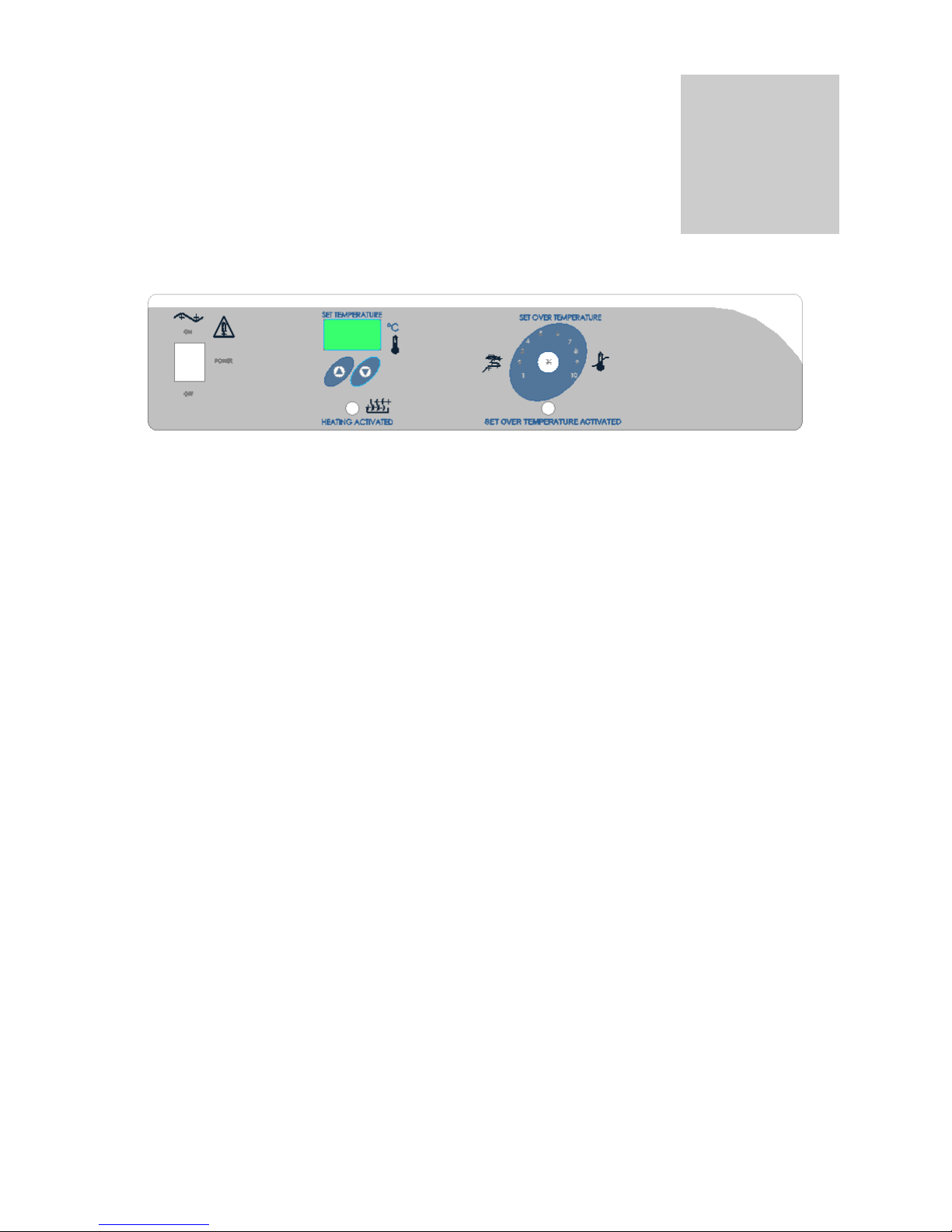
4.1 Power Switch: The main power I/O (on/off) switch controls all power to the unit and must be in
the I/ON position before any systems are operational.
4.2 Main Temperature Control: The Main Temperature Control consists of the digital display and
UP/DOWN arrow pads for inputting set point temperatures and calibration.
4.3 HEATING Lamp: This green pilot lamp in ON when the unit is heating up to set point and is
blinking when controlling temperature at set point.
4.4 Overtemperature Thermostat: Marked SET OVERTEMPERATURE, the Thermostat is a
completely independent control that acts as an override in the event that the Main control fails in
the ON position. The Thermostat will regulate chamber temperature at approximately 1C above
the set point of the Main controller.
4.5 OVER TEMP Lamp: This red pilot lamp is On when the Overtemperature Thermostat has taken
control of the unit. Under normal operating conditions this lamp should never be on.
4.6 Circuit Breaker: (Non-CE units) Located adjacent to the power cord, the circuit breaker is an
added measure of protection against power source variations that, if tripped, can be reset by
pushing in the button once the reason for the interruption has been cleared.
4.7 Fuse: (CE units) Located adjacent to the power cord in place of the circuit breaker. The fuse is
an added measure of protection against power source variations, and if blown must be replace
once the source of the interruption has been cleared.
 Loading...