

VWR International 1330FM, 1350FM, 1370FM1330GM, 1370GM, 1330FMS Installation Manual
...
Sheldon Manufacturing Inc. P.O. Box 627 Cornelius, Oregon 97113
EMAIL: tech@Shellab.com
1-800-322-4897 (503) 640-3000 FAX (503) 640-1366
MICROPROCESSOR
CONTROLLED OVENS
M
ODELS: 1330FM,1350FM,1370FM
1330GM,1350GM,1370GM
1330FMS,1350FMS,1370FMS
1330GMS,1350GMS,1370GMS
I
NSTALLATION AND OPERATION MANUAL
INTERNET: http://www.Shellab.com/~Shellab

TABLE OF CONTENTS
SECTION 1.0 RECEIVING AND INSPECTION
SECTION 2.0 GRAPHIC SYMBOLS
SECTION 3.0 INSTALLATION
SECTION 4.0 PRECAUTIONS
SECTION 5.0 CONTROL PANEL OVERVIEW
SECTION 6.0 OPERATION
SECTION 7.0 MAINTENANCE
SECTION 8.0 TROUBLESHOOTING
SECTION 9.0 PARTS LIST
UNIT SPECIFICATIONS
SCHEMATICS
REV 01/10
4861369
This unit is a special purpose oven for professional, industrial or educational use where the
preparation or testing of materials is done at approximately atmospheric pressure and no
flammable volatile or combustible materials are being heated or placed near or on top of
unit. This unit is not intended for hazardous or household locations or use.
2

S
ection
1
RECEIVING AND INSPECTION
Your satisfaction and safety require a complete understanding of this unit. Read the
instructions thoroughly and be sure that all users are given adequate training before
attempting to use this unit. Note: This equipment must be used only for its intended
purpose; any alterations or modifications will void your warranty.
1.1 Inspection: The carrier, when accepting shipment, also accepts responsibility for
safe delivery and is liable for loss or damage claims. On delivery inspect for visible
exterior damage, note and describe on the freight bill any damage found and enter
your claim on the form supplied by the carrier.
1.2 Inspect for concealed loss or damage on the unit itself, both interior and exterior. If
any, the carrier will arrange for official inspection to substantiate your claim.
1.3 Accessories: Verify that your accessory package is complete. All units are
equipped with a set of four (4) Leveling feet, two (2) shelves and eight (8) shelf clips.
1.4 Return Shipment: Save the shipping crate until you are sure all is well. If for any
reason you must return the unit, contact your customer service representative for
authorization and supply data plate information. Make sure to include the model
and unit serial number. The service representatives will furnish you with a return
authorization number and address for return. Note: Make sure this return
authorization number appears on the unit packaging and shipping papers. Units
returned without proper authorization may not be accepted at the factory. For
information on where to contact Customer Service please see the manual cover.
3
S
ection
2
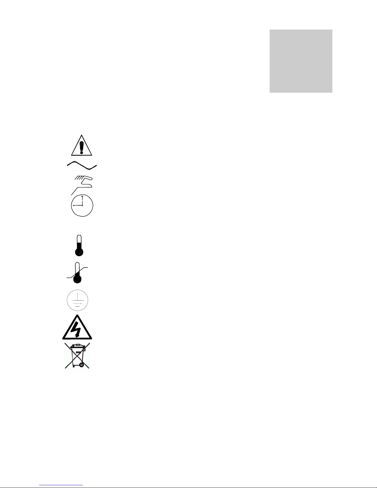
GRAPHIC SYMBOLS
Your oven is provided with a display of graphic symbols which should help in identifying the
use and function of the available user adjustable components.
2.1 This symbol indicates that you should consult your manual for further
description or discussion of a control or user item.
2.2 Indicates “AC Power”.
2.3 Indicates “Manual Control”.
2.4 Indicates “Timer”.
2.5 °C Indicates “Degrees Celsius”.
2.6 Indicates “Temperature”.
2.7 Indicates “Over Temperature Safety”.
2.8 Indicates “Earth Ground”.
2.9 Indicates “Potential Shock Hazard” behind this panel.
2.10 Indicates “Unit should be recycled” (Not disposed of in land-fill)
4

S
ection
3
INSTALLATION
Local city, county or other ordinances may govern the use of this equipment. If you have any questions about
local requirements, please contact the appropriate local agency. Installation may be performed by the end
user.
Under normal circumstance this unit is intended for use indoors, at room temperatures between 5° and 40° C,
at no greater than 80% Relative Humidity ( at 25°C ) and with a supply voltage that does not vary by more
than 10%. Customer service should be contacted for operating conditions outside these limits.
3.1 Power Requirements: The unit power requirements are listed on the units data plate located on the
right front side of the oven. Make sure your power supply matches that shown on the data plate.
VOLTAGE SHOULD NOT VARY MORE THAN 10% FROM THE DATAPLATE RATING. These units
are intended for 50/60HZ application. A separate circuit is recommended to preclude loss of product
due to overloading or circuit failure.
3.2 Location: Select a site for the oven which is free from extreme heat, cold or excessive air movement
such as areas near steam radiators, stoves, other ovens, autoclaves, direct sun, heating and cooling
ducts, etc. Avoid high traffic areas which may reduce the accessibility to the oven. Allow at least
20cm of space between the oven and surrounding walls or partitions which might obstruct free
airflow.
3.3 Lifting / Handling: These units are heavy and care should be taken to use appropriate lifting
devices that are sufficiently rated for these loads. Units should only be lifted from their bottom
surfaces. Doors, handles and knobs are not adequate lifting or stabilization. The unit should be
completely restrained from tipping during lifting or transport. All moving parts, such as shelves and
trays should be removed and doors need to be positively locked in the closed position during transfer
to prevent shifting and damage.
3.4 Leveling: The unit must sit level and solidly. Leveling feet (supplied) are to be installed in the holes
at the base of the oven. Turn them counterclockwise to raise the level and clockwise to lower the
level. If the unit must be moved, turn the leveling feet in all the way to prevent damage.
3.5 Cleaning: The oven’s interior was cleaned at the factory, but not sterilized. Remove all interior parts
if assembled and clean the inside of the chamber thoroughly with a disinfectant that is suitable for
your application. Make sure to rinse the cleaned surface with a damp cloth, using water only, and dry
the surfaces with a clean cloth. DO NOT USE chlorine-based bleaches or abrasives as they will
damage stainless steel surfaces. DO NOT USE spray cleaners that might leak through openings and
cracks and get on electrical parts or that may contain solvents that will harm the coatings. A similar
periodic cleaning is recommended.
WARNING: Never clean the unit with alcohol or flammable cleaners with the unit connected to the
electrical supply. Always disconnect the unit form the electrical service when cleaning and assure all
volatile or flammable cleaners are evaporated and dry before reattaching the unit to the power
supply.
3.6 Burning In: It is recommended that the unit go through a “burning in” process prior to operation. This
is to eliminate the smoking of protective coatings on the element. Read sections 4, 5 and 6 carefully
to understand operating requirements. To burn in turn the Overtemperature Safety to maximum and
set the digital display to 200°. Run for a minimum of one (1) hour under ventilation until smoke
dissipates.
5

Sect
ion
4
PRECAUTIONS
4.1 The bottom surface of the chamber should not be used as a work surface.
4.2 This unit has been designed with a dampered vent from the chamber. In order to
work effectively and safely, some precautions will need to be taken by the operator.
A. In most applications, the exhaust damper will need to be opened during
drying or degassing for best results.
B. THIS OVEN IS NOT DESIGNED TO HANDLE COMBUSTIBLE GASSES
AND IS NOT AN EXPLOSION PROOF UNIT. Do not place explosive,
combustible, or flammable materials into the chamber.
C. Some of the out gassed by-products may be hazardous or unpleasant to
operating personnel. If this is the case, the exhausts should be positively
ventilated to the outside and dealt with according to local regulations. Your
dealer can provide you with a power exhaust which greatly helps under these
applications.
4.3 Do not operate near noxious fumes.
4.4 Do not place sealed or filled containers in the oven chamber.
4.5 Do not cut or remove the ground prong from the power cord.
4.6 Do not use a 2-prong adapter plug.
4.7 Be sure that the power supply is of the same voltage as specified.
4.8 Disconnect the unit from its electrical source before proceeding to make any
electrical repairs or replacements.
4.9 If a mercury thermometer is used and breakage should occur, all spilled mercury
MUST be completely removed from the chamber before continuing operation.
4.10 This oven is NOT designed for the use in Class I, II, or III locations as defined by the
National Electric Code.
4.11 This oven is not intended, nor can it be used, as a patient connected device.
6

S
ection
5
CONTROL PANEL OVERVIEW (See Figure One)
5.1 Power Switch: The main power switch on the control panel (green lighted I/O)
controls all power to the oven. It must be in the I/On position before any systems
are operational. The green pilot light in the switch will be lighted when the switch is
in the ON position.
5.2 Timer Switch: The black I/O power switch marked TIMER is located to the right of
the main power switch. It controls the power to the time circuit. In the O/Off position
the oven heat is controlled with no timed duration. In the I/On position heat is
controlled for a timed interval and then the heat shuts off.
5.3 Overtemperature Safety Thermostat: This control is marked HIGH LIMIT and is
equipped with an adjustment knob and a graduated dial from 0 – 10. It is
independent of the Main Controller and guards against any failure which would
allow temperature to rise past the main controller’s set point. This allows continued
operation of the oven until the problem can be corrected or service can be arranged.
It is not recommended that the unit be operated for extended periods of time using
only the Overtemperature Safety as the temperature controller. On “S” suffix
models, the Overtemperature Safety will shut the oven off by tripping the overtemperature relay. Pushing the red reset button is required to restart the oven after
the interruption reason has been cleared.
5.4 OTP Light: This pilot lamp marked OTP is directly above the Overtemperature
Safety Thermostat. The light will come on when the Safety Thermostat has been
activated and taken over control of the oven. The power to the over-temperature
relay coil is turned OFF for “S” suffix models. Under normal operating conditions
the pilot lamp should never be lit.
5.5 Manual Reset Button: (“S” suffix models only) The red reset button, next to the
OTP light, is for resetting the oven power if the temperature relay has been deactivated. The reset button must be pushed for initial start up and any time
thereafter when there is a power interruption to the Overtemperature relay.
5.6 Timer Control: This control is marked SET/TIMER and consists of a digital display,
UP/DOWN arrow pads, a RESET “PUSH” pad, a START/STOP “PUSH” pad and a
TIMER ACTIVATED light. This control provides the ability to set a timed heat
interval, activate the start-up of the timed heat cycle and shut down the timed heat
cycle automatically.
7

5.7 Main Temperature Controller: This control is marked SET/TEMPERATURE and
consists of the digital display and UP/DOWN arrow pads for inputting set point
temperatures and calibration.
5.8 HEATING Light: This green pilot light is marked TEMPERATURE ACTIVATED
and indicates when the element has been activated and the oven is heating. When
the set point is reached, the pilot light will cycle ON and OFF as the elements
maintain the temperature selected.
Figure One
Control Panel Overview
8
 Loading...