

VWR VisiScope BL384 PI, VisiScope BL384 P, VisiScope BL384 PHI, VisiScope TL384 PH, VisiScope TL384 PHI Instruction Manual
...
VWR
Microscope series 384
INSTRUCTION MANUAL
Model European Catalogue Number
BL384 P 630-1930
TL384 P 630-1931
BL384 PI 630-1932
TL384 PI 630-1933
BL384 PH 630-1934
TL384 PH 630-1935
BL384 PHI 630-2529
TL384 PHI 630-2530
Version: 7
Issued: 20, 10, 2014

Legal Address of Manufacturer
Europe
VWR International bvba
Researchpark Haasrode 2020
Geldenaaksebaan 464
B-3001 Leuven
+ 32 16 385011
http://be.vwr.com
Country of origin: ITALY
Table of Contents
Warning
Safety information
Package contents
Unpacking
Intended use
Symbols and conventions
Product specications
Overview
Automatic Light Control (BL384 P and BL384 PI models)
Operation
Observation head
Place the specimen on the stage
Illumination system settings
Adjust interpupillary distance
Focus tension adjustment
Diopter adjustment
Condenser
Numerical aperture setting
Phase rings centering (models -PH)
Troubleshooting
Repair and maintenance
User replaceable accessories and spare parts
Technical service
Warranty
Compliance with local laws and regulations
Disposal
2

Warning
This microscope is a scientic precision instrument designed to last for many years with a minimum of maintenance. It is built to high optical and mechanical standards and to withstand daily use.
We remind you that this manual contains important information on safety and maintenance, and that it must
therefore be made accessible to the instrument users.
We decline any responsibility deriving from incorrect instrument use uses that does not comply with this
manual.
Safety Information
Avoiding Electrical Shock
Before plugging in the power supply, make sure that the supplying voltage of your region matches with the
operation voltage of the equipment and that the lamp switch is in off position.
Users should observe all safety regulations of the region. The equipment has acquired the CE safety label.
However, users have full responsibility to use this equipment safely.
Please follow the guidelines below, and read this manual in its entirety to ensure safe operation of the unit.
Package Contents
DESCRIPTION QUANTITY
Microscope stand with nosepiece, stage, condenser 1
Optical head ( BL: binocular; TL: trinocular) 1
Objective 4x 1
Objective 10x 1
Objective 40x 1
Objective 100x 1
Eyepiece WF10x/20mm 2
Immersion oil 1
Dust cover 1
Power supply output 6Vdc 1
Unpacking
The microscope is housed in a moulded Styrofoam container. Remove the tape from the edge of the container and lift the top half of the container. Take care to ensure that the optical items (objectives and eyepieces)
do not fall out and get damaged. Using both hands (one around the neck and one around the base), lift the
microscope from the container and put it on a stable desk.
Place the observation head onto the top of the neck and tighten the lock-screw. Insert the eyepieces into the
eye tubes.
Connect the provided power supply to the power supply input jack on the rear of the microscope.
3

Intended use
For research and teaching use only. Not intended for any animal or human therapeutic or diagnostic use.
Symbols and conventions
The following chart is an illustrated glossary of the symbols that are used in this manual.
CAUTION
This symbol indicates a potential risk and alerts you to proceed with
caution
Product specications
Model Head Eyepiece
TL384 P
BL384 P
TL384 PI
BL384 PI
BL384 PH
Trinocular,
360° rotating,
30° inclined
Binocular,
360° rotating,
30° inclined
Trinocular,
360° rotating,
30° inclined
Binocular,
360° rotating,
30° inclined
Binocular,
360° rotating,
30° inclined
Wideeld,
10x/20mm
Wideeld,
10x/20mm
Wideeld,
10x/20mm
Wideeld,
10x/20mm
Wideeld,
10x/20mm
Nosepiece
Quintuple,
reversed
Quintuple,
reversed
Quintuple,
reversed
Quintuple,
reversed
Quintuple,
reversed
Objectives Stage Focusing Illuminator Condenser Power supply
160mm
E-PLAN
4X/0.10,
10X/0.25,
40X/0.65,
100X/1.25
160mm
E-PLAN
4X/0.10,
10X/0.25,
40X/0.65,
100X/1.25
IOS
E-PLAN
4X/0.10,
10X/0.25,
40X/0.65,
100X/1.25
IOS
E-PLAN
4X/0.10,
10X/0.25,
40X/0.65,
100X/1.25
IOS
E-PLAN
4X/0.10,
10XPH/0.25,
40XPH/0.65,
100XPH/1.25
Double layer
160x140mm,
X-Y 76x52mm
moving range.
Double layer
160x140mm,
X-Y 76x52mm
moving range.
Double layer
216x150mm,
X-Y 78x54mm
moving range.
X belt-drive.
Double layer
216x150mm,
X-Y 78x54mm
moving range.
X belt-drive.
Double layer
160x140mm,
X-Y 76x52mm
moving range.
Coaxial coarse
and ne
focusing
Coaxial coarse
and ne
focusing
Coaxial coarse
and ne
focusing
Coaxial coarse
and ne
focusing
Coaxial coarse
and ne
focusing
P-LED system
with adjustable
intensity
P-LED system
with adjustable
intensity.
Automatic brightness control.
P-LED system
with adjustable
intensity
P-LED system
with adjustable
intensity.
Automatic brightness control.
P-LED system
with adjustable
intensity.
Automatic brightness control.
Abbe condenser, slidingin, N.A. 1.25
with centering
system.
Abbe condenser, slidingin, N.A. 1.25
with centering
system.
Abbe condenser, slidingin, N.A. 1.25
with centering
system.
Abbe condenser, slidingin, N.A. 1.25
with centering
system.
Phase condenser (10x,/20x
40x, 100x)
with darkeld
(dry) and
brighteld
External power
supply:
Input 100240Vac 50-60Hz
/ Output 6Vdc
1A
External power
supply:
Input 100240Vac 50-60Hz
/ Output 6Vdc
1A
External power
supply:
Input 100240Vac 50-60Hz
/ Output 6Vdc
1A
External power
supply:
Input 100240Vac 50-60Hz
/ Output 6Vdc
1A
External power
supply:
Input 100240Vac 50-60Hz
/ Output 6Vdc
1A
TL384 PH
BL384 PHI
TL384 PHI
Trinocular,
360° rotating,
30° inclined
Binocular,
360° rotating,
30° inclined
Trinocular
360°rotating
30° inclined
Wideeld,
10x/20mm
Wideeld,
10x/20mm
Wide Field
10X/20
mm
Quintuple,
reversed
Quintuple
nosepiece,
reversed
Quintuple
nosepiece,
reversed
IOS
E-PLAN
4X/0.10,
10XPH/0.25,
40XPH/0.65,
100XPH/1.25
IOS PLAN
10xPh,
20xPh,
40xPh,
00xPh (oil)
PLAN
4x, 10xPh,
40xPh,
100xPh (oil)
Double layer
160x140mm,
X-Y 76x52mm
moving range.
Double layer
mechanical
sliding stage,
216x150mm,
moving range
78x54mm,
Belt-drive in X
direction
Double layer
mechanical
sliding stage,
160x140mm,
moving range
78x54mm
4
Coaxial coarse
and ne
focusing
Coaxial
coarse and
ne focusing
with
limit stop
Coaxial
coarse and
ne focusing
with
limit stop
P-LED system
with adjustable
intensity
P-LED, with
Automatic
Light Control
P-LED, with
manual
brightness
control
Phase condenser (10x,/20x
40x, 100x)
with darkeld
(dry) and
brighteld
Phase condenser
(10x/20x, 40x,
100x)
with darkeld
(dry) and
brighteld
Phase condenser (10x/20x,
40x, 100x)
with darkeld
(dry) and
brighteld
External power
supply:
Input 100240Vac 50-60Hz
/ Output 6Vdc
1A
External power
supply:
Input 100240Vac
50-60Hz.
Output 6Vdc 1A
External power
supply:
Input 100240Vac
50-60Hz.
Output 6Vdc 1A
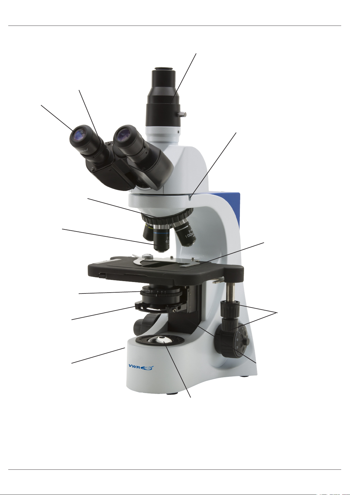
Overview
DIOPTRIC
ADJUSTMENT RING
EYEPIECE
REVOLVING NOSEPIECE
PHOTO/VIDEO PORT
HEAD LOCKING
SCREW (1)
OBJECTIVE
IRIS DIAPHRAGM (3)
CONDENSER
BRIGHTNESS
ADJUSTMENT
(LEFT SIDE)
STAGE
TRANSLATION KNOBS
CONDENSER CENTERING
SCREWS (2)
LED ILLUMINATOR
5

SLIDE CLAMP
INTERPUPILLARY DISTANCE
CONDENSER HEIGHT
ADJUSTMENT (4)
FINE FOCUSING KNOB
COARSE FOCUSING KNOB
FOCUS STOP KNOB
TENSION
ADJUSTMENT KNOB (5)
6
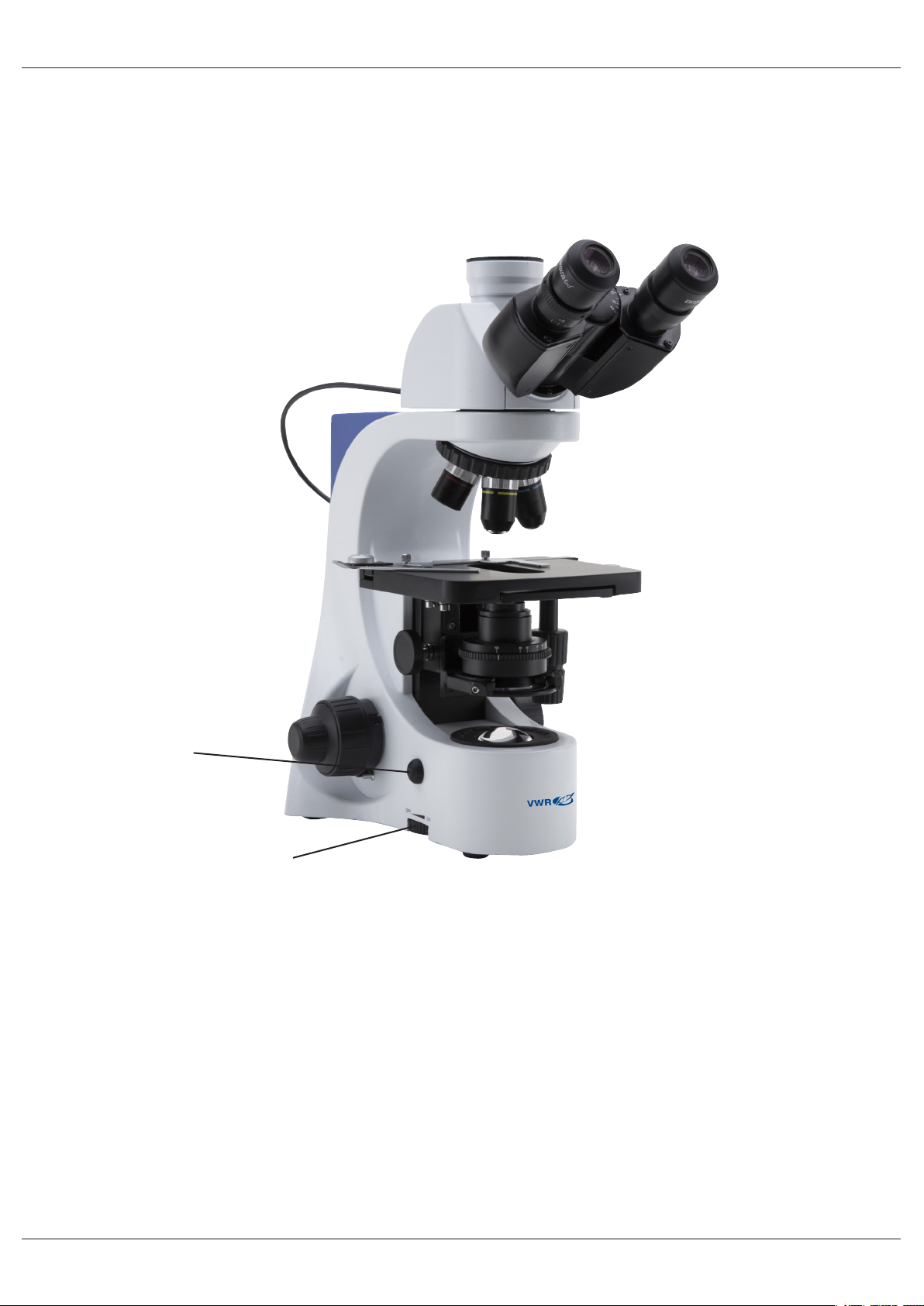
Automatic Light Control (BL384 P, BL384 PI and BL384 PH models)
BL384 P and BL384 PI models have a special function called “Automatic Light Control”.
The level of light is adjusted by the microscope in order to maintain the same level as the one the user has
chosen, no matter if the aperture of the diaphragm changes, another objective is inserted, opacity of the
sample changes, etc.
ALC BUTTON
BRIGHTNESS
ADJUSTMENT
KNOB
1) Set the focus on the sample as described in the previous chapters, using the objective of your choice.
2) Rotate the brightness adjustment knob in order to get a comfortable level of illumination.
NOTE: ALC system works properly with medium-to-high light intensity, do not set the brightness to a
minimum level.
3) Press the ALC button on the side of the microscope.
Now the ALC system is working: if you open or close the aperture diaphragm or change objective, the system
will try to maintain the same level of illumination as the one you stored when you pressed the button.
4) Press the ALC button again to return to a manual control of illumination.
NOTE: ALC system is not suitable for use with phase contrast.
7
Operation
Observation head
Loosen the lock-screw, turn the observation head to a comfortable position for observation, and then lock the
lock-screw.
Place the specimen on the stage
Lock the specimen slide on the mechanical stage using the slide holder. Ensure that the specimen is centred
over the stage opening by adjusting the coaxial stage controls.
Illumination system settings
The microscope is tted with a white LED illuminator. Before turning on the illumination system, read the
section about electrical safety precautions. Insert the plug of the cable into the power socket and turn on the
switch on the back of the main body. Turn the brightness adjustment knob to a brightness suitable for observation.
Adjust interpupillary distance
Hold the right and left side of the observation head with both hands and adjust the interpupillary distance by
turning the two parts until one circle of light can be seen, when looking down the microscope with both eyes.
The white dot (°) placed on the right eyepiece shows the set interpupillary distance. Just remember this value
to help on later settings.
Focus tension adjustment
The tension of the coarse focusing knob is preset by factory. To change the tension according to your preference, just rotate the knob clockwise in order to increase it.
Excessive tension could damage the mechanism of focus. A too loosed tension causes the descent of the
stage by gravity or a sudden loss of focus. In this case, rotate the knob to increase the tension.
Diopter adjustment
Turn the dioptric adjustment ring on the right eyepiece dioptric up to align the bottom with the graduated ring.
Turn the coarse focus knob in order to focus the slide with an objective with low magnication. Adjust the
ne focus knob until you obtain a clear and dened picture observing with the right eye, and then repeat the
operation with the left dioptric compensation ring and the left eye. When the image appears in focus, choose
the necessary objective with the revolving nosepiece.
Condenser
Raise or lower the condenser through the knob to obtain a clear and uniform illumination of the sample.
To center the condenser: completely close the iris diaphragm. Using the condenser centering screws, move
the diaphragm in the center of the eld of view. Then gradually expand the diaphragm until it is tangent to the
edges of the eld of view. If necessary, you can perform an additional adjustment.
The condenser is centered when the edges of iris diaphragm are tangent to the eld of view.
Numerical aperture setting
The value of the numerical aperture (N.A.) of the diaphragm is an indication of the contrast of the illumination
system. Matching the value of illumination system’s N.A. with that of the objective ensures the best results in
terms of contrast and image quality. To set the numerical aperture of the Illuminator, adjust the opening of the
iris diaphragm. In this way you control contrast and image resolution. For samples with low contrast set the
iris to about 75% of the value of the objective’s numerical aperture.
8

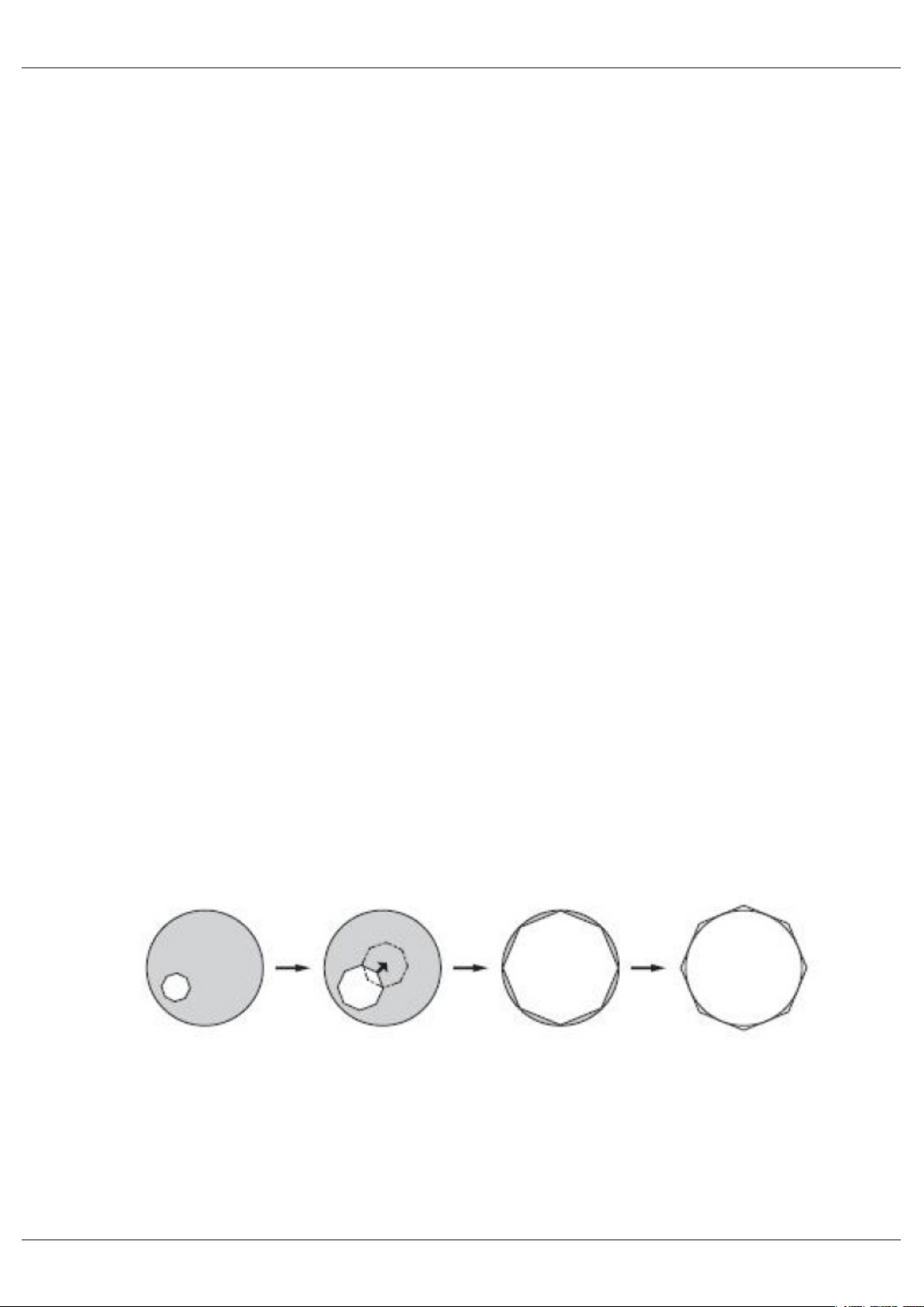
Phase rings centering (models -PH)
For models equipped with phase contrast set, you have to perform the centering of the phase rings.
Remove an eyepiece from the head and insert the centering telescope in the empty tube.
Insert the 10x objective rotating the nosepiece.
Rotate the turret of the condenser until you reach the inscription “10”.
Loosening the lock screw of the centering telescope, focus on the light ring that you observe.
Rotate the two centering screws in order to move the bright ring until it is perfectly aligned with the dark ring.
Repeat for the other objectives (only as a verication of the correct centering).
Phase rings will be centered when you see an image like this:
Troubleshooting
Review the information in the table below to troubleshoot operating problems.
PROBLEM CAUSE SOLUTION
LIGHT DOESN’T TURN ON Power supply not connected Check that the 6Vdc power supply
jack is well inserted on the rear of the
microscope
Rotate the brightness adjustment control and check if there is an increase in
the light output
IMAGE CANNOT BE SEEN OR
IS DARK.
IMAGE IS UNCLEAR, BLURRED
OR HAS INSUFFICIENT CONTRAST.
The iris diaphragm aperture
is not completely opened
Brightness level is low Rotate the brightness adjustment po-
Objective is not aligned with
the optical axis
Objectives or lters are dirty Wipe them clean
The iris diaphragm aperture
is not opened correctly
Condenser at wrong height Rotate the condenser knob until you
Completely open the iris diaphragm
aperture
tentiometer
Rotate the nosepiece until an objective
is well inserted in the optical path (it
“clicks”)
Open the iris diaphragm aperture
completely
see a uniform illumination
9

Repair and maintenance
Microscopy environment
This microscope is recommended for use in a clean, dry and shock free environment with a temperature of
0-40°C and a maximum relative humidity of 85 % (non condensing). Use a dehumidier if needed.
After using the microscope
The microscope should always be kept vertical when moving it so that no moving parts, such as the eyepieces, fall out.
Never mishandle or impose unnecessary force on the microscope. Never attempt to service the microscope
yourself. Turn down the illumination intensity control and turn the light off. Cover the microscope with the included dust cover, and keep it in a dry and clean place.
Electrical safety precautions
Before plugging in the power supply, make sure that the supplying voltage of your region matches with the
operation voltage of the equipment and that the lamp switch is in off-position.
Users should observe all safety regulations of the region. The equipment has acquired the CE safety label.
However, users do have full responsibility to use this equipment safely.
Cleaning the optics
If the optical parts require cleaning rst use compressed air.
If that is not sufcient use a soft lint-free cloth with water and a mild detergent.
And as a nal option use the piece of cloth moistened with a 3:7 mixture of ethanol and ether.
Note: ethanol and ether are highly ammable liquids. Do not use them near a heat source, near sparks or
near electric equipment. Use these chemicals in a well ventilated room.
Remember to never wipe the surface of any optical items with your hands. Fingerprints can damage the optics. Do not disassemble objectives or eyepieces in an attempt to clean them.
For the best results, use the VWR cleaning kit (see catalogue number below).
If you need to send the microscope to manufacturer for maintenance, please use the packaging if possible.
10

User replaceable accessories and spare parts
DESCRIPTION QUANTITY CAT. NO.
Eyepiece WF10x/20mm 2 630-2000
Eyepiece WF15x 2 630-2001
Eyepiece WF20x 2 630-2002
Micrometer eyepiece WF10x/20mm 1 630-2003
Slide micrometric 26x76mm 1mm for 300 1 630-1650
Objective 4x/0,10 E-PLAN 1 630-2004
Objective 10x/0,25 E-PLAN 1 630-2005
Objective 20x/0,40 E-PLAN 1 630-2006
Objective 40x/0,65 E-PLAN 1 630-2007
Objective 60x/0,80 E-PLAN 1 630-2008
Objective 100x/1,25 E-PLAN (Oil) 1 630-2009
Objective E PLAN IOS 4x 1 630-1639
Objective E PLAN IOS 10x 1 630-1640
Objective E PLAN IOS 20x 1 630-1641
Objective E PLAN IOS 40x 1 630-1642
Objective E-PLAN IOS 60x 1 630-2049
Objective E PLAN IOS 100x 1 630-1643
Objective iris diaphragm PL 100x 1 630-1668
Objective 10x/0.25 PLAN for phase contrast. 1 630-2050
Objective 20x/0.40 PLAN for phase contrast. 1 630-2051
Objective 40x/0.65 PLAN for phase contrast. 1 630-2052
Objective 100x/1.25 (oil) PLAN for phase contrast. 1 630-2053
Objective 10x/0.25 IOS PLAN for phase contrast. 1 630-2054
Objective 20x/0.40 IOS PLAN for phase contrast. 1 630-2055
Objective 40x/0.65 IOS PLAN for phase contrast 1 630-2056
Objective 100x/1.25 (oil) IOS PLAN for phase contrast. 1 630-2057
Complete phase contrast set with PLAN obj. 10x, 40x, 100x,
With darkeld condenser for dry objectives.
Complete phase contrast set with IOS PLAN obj. 10x, 20x, 40x,
100x, with darkeld condenser for dry objectives.
Polarizing set (lters only) 1 630-2285
Polarising set, lters only (for 300 series) 1 630-2011
Darkeld condenser for dry objectives. 1 630-2060
1 630-2058
1 630-2059
Phototube adapter for APS-C sensor 1 630-1645
Camera adapter CCD 0,5x 1 630-1644
Heating stage, with digital temperature controller. 1 630-2061
11

Technical service
Web Resources
Visit the VWR’s website at www.vwr.com for:
• Complete technical service contact information
• Access to VWR’s Online Catalogue, and information about accessories and related products
• Additional product information and special offers
Contact us For information or technical assistance contact your local VWR representative or visit. www.
vwr.com.
Warranty
VWR International warrants that this product will be free from defects in material and workmanship for a
period of ve (5) years from date of delivery. If a defect is present, VWR will, at its option and cost, repair,
replace, or refund the purchase price of this product to the customer, provided it is returned during the warranty period. This warranty does not apply if the product has been damaged by accident, abuse, misuse, or
misapplication, or from ordinary wear and tear. If the required maintenance and inspection services are not
performed according to the manuals and any local regulations, such warranty turns invalid, except to the extent, the defect of the product is not due to such non-performance.
Items being returned must be insured by the customer against possible damage or loss. This warranty shall
be limited to the aforementioned remedies. IT IS EXPRESSLY AGREED THAT THIS WARRANTY WILL BE
IN LIEU OF ALL WARRANTIES OF FITNESS AND IN LIEU OF THE WARRANTY OF MERCHANTABILITY.
Compliance with local laws and regulations
The customer is responsible for applying for and obtaining the necessary regulatory approvals or other authorizations necessary to run or use the Product in its local environment. VWR will not be held liable for any
related omission or for not obtaining the required approval or authorization, unless any refusal is due to a
defect of the product.
12

Disposal
This equipment is marked with the crossed out wheeled bin symbol to indicate that this equipment must not
be disposed of with unsorted waste.
Instead it is your responsibility to correctly dispose of your equipment the end of its life cycle by handling it
over to an authorized facility for separate collection and recycling. It is also your responsibility to decontaminate the equipment in case of biological, chemical and/or radiological contamination, so as to protect from
health hazards the persons involved in the disposal and recycling of the equipment.
For more information about where you can drop off your waste equipment, please contact your local dealer
from whom you originally purchased this equipment.
By doing so, you will help to conserve natural and environmental resources and you will ensure that your
equipment is recycled in a manner that protects human health.
Thank you
13

Australia
VWR International, Pty Ltd.
Unit 1/31 Archimedes Place
Murarrie, Queensland 4172
Tel.: 1300 727 696
Fax: 1300 135 123
Austria
VWR International GmbH
Graumanngasse 7
1150 Vienna
Tel.: +43 1 97 002 0
Fax: +43 1 97 002 600
E-mail: info@at.vwr.com
Belgium
VWR International bvba
Researchpark Haasrode 2020
Geldenaaksebaan 464
3001 Leuven
Tel.: 016 385 011
Fax: 016 385 385
E-mail: customerservice@be.vwr.com
China
VWR International China Co., Ltd
Rm.219, 2100 Dongming Road
Pudong New District
Shanghai 200123
Tel.: +86-21-5898 6888
Fax: +86-21-5855 8801
E-mail: info_china@vwr.com
Czech Republic
VWR International s. r. o.
Veetee Business Park
Pražská 442
CZ - 281 67 Stříbrná Skalice
Tel.: +420 321 570 321
Fax: +420 321 570 320
E-mail: info@cz.vwr.com
Denmark
VWR - Bie & Berntsen
Transformervej 8
2730 Herlev
Tel.: 43 86 87 88
Fax: 43 86 87 90
E-mail: info@dk.vwr.com
Finland
VWR International Oy
Valimotie 9
00380 Helsinki
Tel.: 09 80 45 51
Fax: 09 80 45 52 00
E-mail: info@fi .vwr.com
France
VWR International S.A.S.
Le Périgares – Bâtiment B
201, rue Carnot
94126 Fontenay-sous-Bois cedex
Tel.: 0 825 02 30 30 (0,15 € TTC/min)
Fax: 0 825 02 30 35 (0,15 € TTC/min)
E-mail: info@fr.vwr.com
Germany
VWR International GmbH
Hilpertstraße 20a
D - 64295 Darmstadt
Freecall: 0800 702 00 07
Fax: 0180 570 22 22*
Email: info@de.vwr.com
*0,14 €/Min. aus d. dt. Festnetz
Hungary
VWR International Kft.
Simon László u. 4.
4034 Debrecen
Tel.: (52) 521-130
Fax: (52) 470-069
E-mail: info@hu.vwr.com
India
VWR Lab Products Private Limited
135/12, Brigade Towers, 2nd Floor
Front wing, Brigade Road,
Bengaluru, India – 560 025
Tel.: +91-80-41117125/26 (Bengaluru)
Tel.: +91-2522-647911/922 (Mumbai)
Fax: +91-80-41117120
E-mail: vwr_india@vwr.com
Ireland / Northern Ireland
VWR International Ltd /
VWR International (Northern Ireland) Ltd
Orion Business Campus
Northwest Business Park
Ballycoolin
Dublin 15
Tel.: 01 88 22 222
Fax: 01 88 22 333
E-mail: sales@ie.vwr.com
Italy
VWR International PBI S.r.l.
Via San Giusto 85
20153 Milano (MI)
Tel.: 02-3320311/02-487791
Fax: 800 152999/02-40090010
E-mail: info@it.vwr.com
The Netherlands
VWR International B.V.
Postbus 8198
1005 AD Amsterdam
Tel.: 020 4808 400
Fax: 020 4808 480
E-mail: info@nl.vwr.com
New Zealand
Global Science - A VWR Company
241 Bush Road
Albany 0632, Auckland
Tel.: 0800 734 100
Fax: 0800 999 002
E-mail: sales@globalscience.co.nz
Norway
VWR International AS
Haavard Martinsens vei 30
0978 Oslo
Tel.: 02290
Fax: 815 00 940
E-mail: info@no.vwr.com
Poland
VWR International Sp. z o.o.
Limbowa 5
80-175 Gdansk
Tel.: 058 32 38 200 do 204
Fax. 058 32 38 205
E-mail: info@pl.vwr.com
Portugal
VWR International -
Material de Laboratório, Lda
Edifício Neopark
Av. Tomás Ribeiro, 43- 3 D
2790-221 Carnaxide
Tel.: 21 3600 770
Fax: 21 3600 798/9
E-mail: info@pt.vwr.com
Singapore
VWR Singapore Pte Ltd
18 Gul Drive
Singapore 629468
Tel.: +65 6505 0760
Fax: +65 6264 3780
E-mail: sales@sg.vwr.com
Spain
VWR International Eurolab S.L.
C/ Tecnología 5-17
A-7 Llinars Park
08450 - Llinars del Vallès
Barcelona
Tel.: 902 222 897
Fax: 902 430 657
E-mail: info@es.vwr.com
Sweden
VWR International AB
Fagerstagatan 18a
163 94 Stockholm
Tel.: 08 621 34 00
Fax: 08 621 34 66
E-mail: kundservice@se.vwr.com
Switzerland
VWR International GmbH
Lerzenstrasse 16/18
8953 Dietikon
Tel.: 044 745 13 13
Fax: 044 745 13 10
E-mail: info@ch.vwr.com
Turkey
Pro Lab Laboratuar Teknolojileri Ltd.Şti.
a VWR International Company
Orta Mah. Cemal Gürsel Caddesi
Ördekcioglu Işmerkezi No.32/1
34896 Pendik - Istanbul
Tel.: +90216 598 2900
Fax: +90216 598 2907
Email: info@pro-lab.com.tr
UK
VWR International Ltd
Customer Service Centre
Hunter Boulevard - Magna Park
Lutterworth
Leicestershire
LE17 4XN
Tel.: 0800 22 33 44
Fax: 01455 55 85 86
E-mail: uksales@uk.vwr.com
GO TO VWR.COM FOR THE
LATEST NEWS, SPECIAL OFFERS
AND DETAILS OF YOUR LOCAL
VWR DISTRIBUTOR
14

VWR
Microscope series 384
MANUEL D’UTILISATION
Modèle European Catalogue Number
BL384 P 630-1930
TL384 P 630-1931
BL384 PI 630-1932
TL384 PI 630-1933
BL384 PH 630-1934
TL384 PH 630-1935
BL384 PHI 630-2529
TL384 PHI 630-2530
Version: 7
du: 20, 10, 2014

Adresse du Fabricant
Europe
VWR International bvba
Researchpark Haasrode 2020
Geldenaaksebaan 464
B-3001 Leuven
+ 32 16 385011
http://be.vwr.com
Pays d’origine: ITALIA
Contenu
Avertissement
Précautions
Contenu de l’emballage
Déballage
Usage
Symboles et conventions
Caractéristiques techniques
Description
Contrôle automatique de l’éclairage (modèles BL384 P et BL384 PI)
Utilisation
Tête d’observation
Positionnement de la préparation sur la platine porte préparation
Réglage de la luminosité
Réglage de la distance inter-pupillaire
Réglage de la mise au point
Réglage de la compensation dioptrique
Réglage du condenseur
Réglage de l’ouverture numérique
Centrage des anneuax de phase (-PH)
Résolution de problèmes
Réparation et entretien
Accessoires et pièces de rechanges
Service technique
Garantie
Conformité à la législation et aux réglementations locales
Ramassage
16

Avertissement
Le présent microscope est un appareil scientique de précision créé pour offrir une durrée de vie de plusieurs
années avec un niveau d’entretien mininum. Les meilleurs composants optiques et mécaniques ont été utilisés pour sa conception ce qui fond de lui un appareil idéal pour une utilisation journalière.
Ce guide contient des informations importantes sur la sécurité et l’entretien du produit et par conséquent il
doit être accessible à tous ceux qui utilisent cet insrument.
Nous déclinons toute responsabilité quant à des utilisations de l’instrument non conformes au présent manuel.
Précautions
Précautions de sécurité sur le système électrique
Avant de connecter le câble d’alimentation au réseau électrique assurez vous que la tension d’entrée soit
compatible avec celle de l’appareil et que l’interrupteur de l’éclairage soit en position arrêt.
L’utilisateur devra consulter les normes de sécurités de son pays. L’appareil inclu une étiquette de sécurité
C.E. Dans tous les cas, l’utilisateur assume toute responsabilité relative à l’utilisation sûre de l’appareil.
Suivre les directives ci-dessous et lire ce manuel dans son intégralité pour un fonctionnement sûr de l’instrument.
Contenu de l’emballage
DESCRIPTION QUANTITÉ
Statif du microscope avec revolver, platine, condenseur 1
Tête optique (BL: binoculaire; TL: trinoculaire) 1
Objectif 4x 1
Objectif 10x 1
Objectif 40x 1
Objectif 100x 1
Oculaires WF10x/20mm 2
Huile à immersion 1
Housse de protection 1
Alimentation 6Vdc 1
Déballage
Le microscope est livré dans un emballage en polystyrène. Après avoir enlevé le papier adhésif de l’emballage, enlevez la partie supérieure de l’emballage. Faites attention à ce que les composants optiques (objectifs et oculaires) ne tombent pas ou ne s’endommagent pas. Sortez le microscope de son emballage et posez
le sur une surface stable et plate.
Fixez la tête d’observation sur la partie supérieure du corps du microscope en utilisant les vis de xation correspondantes. Introduisez l’oculaire dans le porte oculaire.
Connectez l’alimentation à la prise jack située sur partie postérieure du microscope.
17

Usage
Uniquement pour la recherche. Non destiné à usage thérapeutique ou diagnostique sur animaux ou êtres
humains.
Symboles et conventions
Le tableau suivant est un glossaire illustré des symboles qui sont utilisés dans ce manuel.
ATTENTION
Ce symbole indique un risque potentiel et vous avertit de procéder
avec prudence
Caractéristiques techniques
Modèle Tête Oculaires Revolver Objectifs Platine Mise au point Éclairage Condenseur Alimentation
TL384 P
BL384 P
TL384 PI
BL384 PI
BL384 PH
TL384 PH
BL384 PHI
TL384 PHI
Trinoculaire,
rotative sur
360°,
inclinée à
30°
Binoculaire,
rotative sur
360°,
inclinée à
30°
Trinoculaire,
rotative sur
360°,
inclinée à
3 0 °
Binoculaire,
rotative sur
360°,
inclinée à
3 0 °
Binoculaire,
rotative sur
360°,
inclinée à
3 0 °
Trinoculaire,
rotative sur
360°,
inclinée à
3 0 °
Binoculaire
rotative sur
360°,
inclinée à 30
Trinoculaire
rotative sur
360°,
inclinée à
30°
WF
10x/20mm
WF
10x/20mm
WF
10x/20mm
WF
10x/20mm
WF
10x/20mm
WF
10x/20mm
WF
10x/20mm
WF
10x/20mm
5 positions,
inversé
5 positions,
inversé
5 positions,
inversé
5 positions,
inversé
5 positions,
inversé
5 positions,
inversé
5 positions
incliné
5 positions
incliné
160mm
E-PLAN
4X/0.10,
10X/0.25,
40X/0.65
100X/1.25
160mm
E-PLAN
4X/0.10,
10X/0.25,
40X/0.65
100X/1.25
IOS
E-PLAN
4X/0.10,
10X/0.25,
40X/0.65
100X/1.25
IOS
E-PLAN
4X/0.10,
10X/0.25,
40X/0.65
100X/1.25
IOS
E-PLAN
4X/0.10,
10XPH/0.25,
40XPH/0.65,
100XPH/1.25
IOS
E-PLAN
4X/0.10,
10XPH/0.25,
40XPH/0.65,
100XPH/1.25
IOS PLAN
10xPh,
20xPh,
40xPh,
100xPh
(huile)
IOS PLAN
10xPh,
20xPh,
40xPh,
100xPh
(huile)
Avec surplatine
160x140mm,
rang de mouvement
X-Y 76x52mm.
Avec surplatine
160x140mm,
rang de mouvement
X-Y 76x52mm.
Avec surplatine
216x150mm,
rang de mouvement
X-Y 78x54mm.
Avec surplatine
216x150mm,
rang de mouvement
X-Y 78x54mm.
Avec surplatine
160x140mm,
rang de mouvement
X-Y 76x52mm.
Avec surplatine
160x140mm,
rang de mouvement
X-Y 76x52mm.
Platine avec
sur-platine
216x150 mm.
Rang x,y
78x54mm.
Entraînement
par courroie
en direction X
Platine avec
sur-platine
216x150 mm.
Rang x,y
78x54mm.
Entraînement
par courroie
en direction X
18
Macrométrique
et micrométrique
coaxiale
Macrométrique
et micrométrique
coaxiale
Macrométrique
et micrométrique
coaxiale
Macrométrique
et micrométrique
coaxiale
Macrométrique
et micrométrique
coaxiale
Macrométrique
et micrométrique
coaxiale
Macrométrique
et micrométrique
coaxiale avec système d’arrêt de
securité
Macrométrique
et micrométrique
coaxiale avec système d’arrêt de
securité
P-LED3 avec
variateur d’intensité lumineuse
P-LED3 avec
variateur d’intensité lumineuse.
contrôle
automatique de
l’éclairage
P-LED3 avec
variateur d’intensité lumineuse
P-LED3 avec
variateur d’intensité lumineuse.
contrôle
automatique de
l’éclairage
P-LED3 avec
variateur d’intensité lumineuse.
contrôle
automatique de
l’éclairage
P-LED3 avec
variateur d’intensité lumineuse
P-LED3, avec
contrôle
automatique
de la lumière
P-LED3, avec
variateur
d’intensité
manuel
Condenseur
d’Abbe, extractible, O.N 1.25
avec système
de centrage
Condenseur
d’Abbe, extractible, O.N 1.25
avec système
de centrage
Condenseur
d’Abbe, extractible, O.N 1.25
avec système
de centrage
Condenseur
d’Abbe, extractible, O.N 1.25
avec système
de centrage
Condensateur
pour contraste
de phase
(10x/20x, 40x,
100x) avec
fond noir (sec)
et fond clair
Condensateur
pour contraste
de phase
(10x/20x, 40x,
100x) avec
fond noir (sec)
et fond clair
Pour contraste
de phase
(10x/20x, 40x,
100x) avec
fond
noir ( à sec) et
fond clair
Pour contraste
de phase
(10x/20x, 40x,
100x) avec
fond
noir ( à sec) et
fond clair
Alimentation
externe:
entrée 100240Vac 5060Hz / sortie
6Vdc 1A
Alimentation
externe:
entrée 100240Vac 5060Hz / sortie
6Vdc 1A
Alimentation
externe:
entrée 100240Vac 5060Hz / sortie
6Vdc 1A
Alimentation
externe:
entrée 100240Vac 5060Hz / sortie
6Vdc 1A
Alimentation
externe:
entrée 100240Vac 5060Hz / sortie
6Vdc 1A
Alimentation
externe:
entrée 100240Vac 5060Hz / sortie
6Vdc 1A
Alimentation
externe:
entrée 100240Vac 5060Hz
/ sortie 6Vdc 1A
Alimentation
externe:
entrée 100240Vac 5060Hz
/ sortie 6Vdc 1A

Description
OCULAIRES
SORTIE PHOTO VIDÉO
RÉGLAGE DE LA DISTANCE
INTER PUPILLAIRE
VIS DE FIXATION DE
LA TÊTE (1)
RÉVOLVER
OBJECTIFS
DIAPHRAGME À IRIS (3)
CONDENSEUR
AJUSTEMENT
LUMINOSITE
(CÔTÉ GAUCHE)
SURPLATINE
MÉCANIQUE
COMMANDES
COAXIALES
VIS DE RÉGLAGE DE
CONDENSEUR (2)
ECLAIRAGE LED
19

PINCE POUR MAINTENIR LES
PRÉPARATIONS
RÉGLAGE DE LA DISTANCE
INTER PUPILLAIRE
RÉGLAGE DE LA
HAUTEUR DU
CONDENSEUR (4)
COMMANDE DE MISE AU
POINT MICROMÉTRIQUE
COMMANDE DE MISE
AU POINT
MACROMÉTRIQUE
VERROUILLAGE DU
FOYER
COMMANDE DE
RÉGLAGE DE TENSION
(5)
20

Contrôle automatique de l’éclairage (modèles BL384 P, BL384 PI et BL384 PH)
Les modèles BL384 P et BL384 PI sont équipés d’une fonction spéciale appelée “Automatic Light
Control” (Contrôle automatique de l’éclairage).
Le niveau de la lumière est réglé par le microscope de manière à maintenir le niveau sélectionné par l’utilisateur, indépendamment de la variation du diaphragme d’ouverture, de l’insertion d’un objectif différent, de
l’opacité de l’échantillon, etc.
COMMANDE POUR ALC
COMMANDE DE
RÉGLAGE DE
L’INTENSITÉ
1) Mettre au point l’échantillon (comme décrit dans les précédents chapitres), en utilisant l’objectif choisi.
2) Tourner la commande de réglage de l’intensité de manière à obtenir le niveau désiré de l’éclairage.
REMARQUE: Le système ALC fonctionne correctement avec l’intensité lumineuse moyenne ou forte,
ne réglez pas la luminosité à un niveau minimum.
3) Appuyer la commande ALC sur le côté du microscope
Maintenant, le système ALC fonctionne: si vous ouvrez ou fermez le diaphragme ou vous changez
l’ objectif, le système maintient le niveau de lumière correspondant à celui enregistrée en appuyant la
commade ALC.
4) Appuyez à nouveau la commande ALC pour retourner aux contrôle manuel de l’éclairage.
ATTENTION: le système ALC n’est pas adapté en cas d’utilisation en contraste de phase.
21

Utilisation
Tête d’observation
Dévissez la vis de xation, tournez la tête du microscope jusqu’à obtenir une position confortable pour l’observation et xez à nouveau la vis.
Positionnement de la préparation sur la platine porte préparation
Fixez la préparation sur la platine en utilisant les valets correspondants. Réglez les commandes coaxiales
pour vous assurer que la préparation se situe bien au centre du champ de vision.
Réglage de la luminosité
Le microscope inclus un éclairage LED blanc. Avant de mettre en marche l’éclairage, lisez attentivement la
section concernant les précautions de sécurité électrique. Branchez la prise d’alimentation sur la douille jack
située à l’arrière du microscope. Tournez le bouton de réglage de la lumière et sélectionnez l’intensité lumineuse correcte pour l’observation.
Réglage de la distance inter-pupillaire
Tenez avec les deux mains les parties gauche et droite de la tête d’observation et réglez la distance interpupillaire des tubes porte oculaires en bougeant les deux parties jusqu’à l’observation d’un seul et unique
cercle lumineux. Le point blanc(°) sur l’oculaire droit indique la distance interpupillaire choisie. Rappelez vous
de cette valeure pour la prochaine utilisation
Réglage de la mise au point
La tension de mise aur point macrométrique a déja été preglée. Pour modier la tension tourner la commande
dans le sens des aiguilles d’une montre pour augmenter la tension. Une tension trop forte pourrait endommager le mécanisme de la mise au point. Une tension trop faible provoque la descente de la platine par pesanteur ou une perte de mise au poit soudaine. Dans ce cas tourner la commande pour augmenter la tension
Réglage de la compensation dioptrique
Tourner l’anneau de réglage dioptrique sur l’oculaire droit jusqu’à ce que la partie inférieure s’aligne à l’an-
neau gradué. Enlevez la vis qui xe le bouton de l’ouverture de mise au point et desserrez le bouton. Faites
la mise au point de la préparation en tournant la commande micrométrique et en utilisant l’objectif le plus
faible, puis bloquez à nouveau le bouton. En observant de l’oeil gauche, réglez la commande micrométrique
an d’obtenir une image nette. Répétez l’opération avec l’oeil droit et la commande de droite. En tournant le
bouton de réglage de tension, réglez la tension adaptée à la mise au point. Lorsque l’image est nette, sélectionnez l’objectif souhaité.
Réglage du condenseur
Montez ou descendez le condenseur en utilisant la commande correspondante an d’obtenir un éclairage
clair et uniforme de l’objet. Per centrer le condenseur: en utilisant l’anneau de réglage du diaphragme à iris,
fermer complètement le diaphragme. En utilisant les vis de centrage du condenseur, déplacer le diaphragme
au centre du champ visuel. élargir de façon graduelle le diaphragme jusqu’à ce qu’il soit tangent au bord du
champ visuel. Si celà est nécessaire, effectuer une nouvelle fois le réglage.
Le condenseur est centré quand les bords du diaphragme sont tous tangents au champ visuel.
Réglage de l’ouverture numérique
La valeur de l’ouvérture numérique (N.A.) du diaphragme est l’indication du contraste du système d’éclairage.
Quand la valeur de l’ouverture numèrique N.A du système d’éclairage coincide avec celle de l’objectif, on
obtient le meilleur contraste et la meilleure qualité de l’image. Réglez l’ouverture numérique du diaphragme
à iris pour sélectionner l’ouverture numérique de l’éclairage, en permettant de cette manière contrôler le
contraste et la résolution de l’image. Pour les préparation avec faible contraste régler le diaphragme à 75%
de la valeur de l’ouverture numérique de l’objectif.
22

Centrage des anneuax de phase (-PH)
En ce qui concerne les modèles munis d’observation à contraste de phase il est nécessaire d’éffectuer le
centrage des anneaux de phase.
Sortir un oculaire du tube porte oculaie et enler le teléscope de centrage dans le porte oculaire vide.
Choisir l’objectif 10x en tournat le revolver.
Tourner la tourelle du condenseur jusqu’à ce que vous voyez l’inscription “10”.
Régler la mise au point de l’anneau lumineux que vous observez en dessérant la vis du télescope de centrage.
Tournez les deux vis de centrage an de déplacer l’anneau lumineux jusqu’à ce qu’il soit parfaitement aligné
avec l’anneau sombre.
Repèter l’operation ave les autres objectifs (pour vérier que le centrage ait été bien fait).
Les anneaux de phase sont centré quand vous pouvez observez cette image:
Résolution de problèmes
PROBLÈME CAUSE SOLUTION
L’ÉCLAIRAGE NE
S’ALLUME PAS
L’IMAGE NE SE VOIT PAS OU
EST SOMBRE.
L’IMAGE EST FLOUE OU LE
CONTRASTE EST
INSUFFISANT
L’alimentation n’est pas
branché
Potentiomètre Tourner le potentiomètre de réglage de
Le diaphragme n’est pas
complètement ouvert.
Le niveau de luminosité est
faible.
L’objectif n’est pas aligné
avec l’axe optique.
Les objectifs ou les ltres
sont sales.
Le diaphragme n’est pas
complètement ouvert.
Le condenseur n’est pas à la
bonne hauteur
Vériez l’alimentation 6Vdc soit bien
inséré à l’arrière du microscope.
la luminosité et vérier si une augmentation de lumière se produit.
Ouvrez complètement le diaphragme
Tourner le potentiomètre de réglage de
la luminosité.
Tournez le revolver jusqu’à ce que
l’objectif soit bien aligné dans le trajet
optique, vous entendrez un « clic »
Les nettoyer.
Ouvrez complètement le diaphragme.
Tournez la commande du condensateur jusqu’à vous voyez un éclairage
uniforme
23

Réparation et entretien
Environnement de travail
Il est conseillé d’utiliser le microscope dans un environnement propre et sec, protégé des impactes, à une
température comprise entre 0°C y 40°C et avec une humidité relative maximale de 85% (en absence de
condensation). Il est conseillé d’utiliser un déshumidicateur si nécessaire.
Conseils avant et après l’utilisation du microscope
- Maintenir le microscope toujours en position verticale lorsque vous le déplacez. Assurez vous que les
pièces mobiles (oculaires) ne tombent pas.
- Manipulez avec attention le microscope en évitant de le forcer.
- Ne réparez pas le microscope vous même
- Éteindre immédiatement la lumière après avoir utilisé le microscope, couvrez le avec la housse prévue à cet
effet et conservez le dans un endroit propre et sec.
Précaution de sécurité sur le système électrique
Avant de connecter le câble d’alimentation sur le réseau électrique assurez vous que la tension d’entrée soit
compatible avec celle de l’appareil et que l’interrupteur de l’éclairage soit en position arrêt.
L’utilisateur devra consulter les normes de sécurités de son pays. L’appareil inclu une étiquette de sécurité
C.E. Dans tous les cas, l’utilisateur assume toute responsabilité relative à l’utilisation sûre de l’appareil.
Nettoyage des optiques
Si vous souhaitez nettoyer les optiques, utilisez dans un premier temps de l’air comprimé Si cela n’est pas
sufsant, utilisez alors un chiffon non efloché, humidié avec un peu d’eau et avec un détergent délicat.
Comme dernière option, il est possible d’utiliser un chiffon humide avec une solution de 3:7 d’éthanol et
d’éther. Attention: l’éthanol et l’éther sont des substances hautement inammables.
Ne les utilisez pas près d’une source de chaleur, d’étincelles ou d’appareils électriques.
Les substances chimiques doivent être utilisées dans un environnement aéré Ne pas frotter la supercie
d’aucun des composants optiques avec les mains. Les empreintes digitales peuvent endommager les parties
optiques.
Pour les meilleurs résultats, utiliser le kit de nettoyage (code ci-dessous).
Conserver l’emballage d’origine dans le cas où il serait nécessaire de retourner le microscope au
fournisseur pour un entretien ou une réparation.
24

Accessoires et pièces de rechanges
DESCRIPTION QUANTITÉ CAT. NO.
Oculaires WF10x/20mm 2 630-2000
Oculaires WF15x 2 630-2001
Oculaires WF20x 2 630-2002
Oclulaire micromètrique WF10x/20mm 1 630-2003
Slide micrometrique 26x76mm 1mm 1 630-1650
Objectif 4x/0,10 E-PLAN 1 630-2004
Objectif 10x/0,25 E-PLAN 1 630-2005
Objectif 20x/0,40 E-PLAN 1 630-2006
Objectif 40x/0,65 E-PLAN 1 630-2007
Objectif 60x/0,80 E-PLAN 1 630-2008
Objectif 100x/1,25 E-PLAN (huile) 1 630-2009
Objectif E PLAN IOS 4X 1 630-1639
Objectif E PLAN IOS 10x 1 630-1640
Objectif E PLAN IOS 20x 1 630-1641
Objectif E PLAN IOS 40x 1 630-1642
Objectif E-PLAN IOS 60x 1 630-2049
Objectif E PLAN IOS 100x 1 630-1643
Objectif diaphragme a iris PL 100X 1 630-1668
Objectif 10x/0.25 PLAN pour contraste de phase 1 630-2050
Objectif 20x/0.40 PLAN pour contraste de phase 1 630-2051
Objectif 40x/0.65 PLAN pour contraste de phase 1 630-2052
Objectif 100x/1.25 (huile) PLAN pour contraste de phase 1 630-2053
Objectif 10x/0.25 IOS PLAN pour contraste de phase 1 630-2054
Objectif 20x/0.40 IOS PLAN pour contraste de phase 1 630-2055
Objectif 40x/0.65 IOS PLAN pour contraste de phase 1 630-2056
Objectif 100x/1.25 (huile) IOS PLAN pour contraste de phase 1 630-2057
Kit pour contraste de phase avec obj. PLAN 10x, 40x, 100x,
avec condenseur pour fond noir pour obj. Secs
Kit pour contraste de phase avec obj.IOS PLAN 10x, 20x, 40x,
100x, avec condenseur pour fond noir pour obj. Secs
Kit de polarisation, seulement les ltres (pour série 300) 1 630-2285
Platine tournante pour kit de polarisation 1 630-2011
Condenseur pour fond noir pour objetifs secs 1 630-2060
Adaptateur camera reex APS-C sensor 1 630-1645
Adaptateur 0,5X CCD 1 630-1644
Platine chauffante, avec contrôlede la température numérique 1 630-2061
25
1 630-2058
1 630-2059

Service technique
Ressources Web
Visitez le site Web de VWR à l’adresse www.vwr.com pour:
• Coordonnées complètes du service technique.
• Accès au catalogue en ligne de VWR et à des informations sur les accessoires et produits connexes.
• Informations supplémentaires sur les produits et les offres spéciales.
Contactez-nous Pour plus d’informations ou une assistance technique, contactez votre représentant VWR
local ou visitez le site www.vwr.com.
Garantie
VWR International garantit ce produit pièces et main-d’œuvre pour une durée de cinq (5) ans à compter
de la date de livraison. En cas de vice, VWR pourra, à sa discrétion et à ses frais, réparer, remplacer ou
rembourser au client le prix d’achat du produit, à condition qu’il lui soit retourné au cours de la période de
garantie. Cette garantie n’est pas applicable si le dommage provient d’un accident, d’une utilisation abusive
ou incorrecte, d’une mauvaise application ou de l’usure normale du produit. Cette garantie deviendrait non
valide dans le cas où les services de maintenance et de vérication requis ne seraient pas exécutés conformément aux manuels et réglementations locales, sauf exception si le défaut du produit n’est pas imputable
à cette non exécution.
Il est recommandé au client d’assurer les éléments retournés contre les risques éventuels d’endommagement
ou de perte. Cette garantie se limite aux réparations susmentionnées. IL EST EXPRESSÉMENT CONVENU
QUE LA PRÉSENTE GARANTIE SE SUBSTITUE À TOUTES LES GARANTIES DE CONFORMITÉ ET DE
VALEUR MARCHANDE.
Conformité à la législation et aux réglementations locales
Le client est chargé de la demande et de l’obtention des approbations réglementaires et autres autorisations
nécessaires à l’utilisation ou à l’exploitation du Produit dans l’environnement local. VWR ne saura être tenu
responsable de toute omission ou non obtention des approbations ou autorisations requises, sauf exception
si le refus est dû à un défaut du produit.
26
Ramassage
Le symbole du conteneur qui gure sur l’appareil électrique ou sur son emballage indique que le produit devra être, à la n de sa vie utile, séparé du reste des résidus. Pour la gestion du ramassage sélectif du présent
instrument, l’utilisateur qui souhaite éliminer l’appareil devra se mettre en contact avec le fabricant et suivre
la procédure que celui-ci a adopté pour permettre le ramassage sélectif de l’appareil. Le ramassage sélectif
correct de l’appareil pour son recyclage, traitement et élimination compatible avec l’environnement contribue
à éviter d’éventuels effets négatifs sur l’environnement et la santé et favorise la réutilisation et/ou recyclage
des composants de l’appareil. L’élimination du produit de manière abusive de la part de l’utilisateur entraînera
l’application de sanctions administratives sur la norme en vigueur.
Merci.
27

Allemagne
VWR International GmbH
Hilpertstraße 20a
D - 64295 Darmstadt
Freecall: 0800 702 00 07
Fax: 0180 570 22 22*
Email: info@de.vwr.com
*0,14 €/Min. aus d. dt. Festnetz
Australie
VWR International, Pty Ltd.
1/31 Archimedes Place
Murarrie, Queensland, 4172
Tel.: 1300 727 696
Fax: 1300 135 123
Autriche
VWR International GmbH
Graumanngasse 7
1150 Wien
Tel.: 01 97 002 0
Fax: 01 97 002 600
E-mail: info@at.vwr.com
Belgique
VWR International bvba
Researchpark Haasrode 2020
Geldenaaksebaan 464
3001 Leuven
Tel.: 016 385 011
Fax: 016 385 385
E-mail: customerservice@be.vwr.com
Chine
VWR International China Co., Ltd
Rm.219, 2100 Dongming Road
Pudong New District
Shanghai 200123
Tel.: +86-21-5898 6888
Fax: +86-21-5855 8801
E-mail: info_china@vwr.com
Danemark
VWR - Bie & Berntsen
Transformervej 8
2730 Herlev
Tel.: 43 86 87 88
Fax: 43 86 87 90
E-mail: info@dk.vwr.com
Espagne
VWR International Eurolab S.L.
C/ Tecnología 5-17
A-7 Llinars Park
08450 - Llinars del Vallès
Barcelona
Tel.: 902 222 897
Fax: 902 430 657
E-mail: info@es.vwr.com
Finlande
VWR International Oy
Valimotie 9
00380 Helsinki
Tel.: 09 80 45 51
Fax: 09 80 45 52 00
E-mail: info@fi .vwr.com
France
VWR International S.A.S.
Le Périgares – Bâtiment B
201, rue Carnot
94126 Fontenay-sous-Bois cedex
Tel.: 0 825 02 30 30 (0,15 € TTC/min)
Fax: 0 825 02 30 35 (0,15 € TTC/min)
E-mail: info@fr.vwr.com
Hongrie
VWR International Kft.
Simon László u. 4.
4034 Debrecen
Tel.: (52) 521-130
Fax: (52) 470-069
E-mail: info@hu.vwr.com
Inde
VWR Lab Products Private Limited
135/12, Brigade Towers, 2nd Floor
Front wing, Brigade Road,
Bengaluru, India – 560 025
Tel.: +91-80-41117125/26 (Bengaluru)
Tel.: +91-2522-647911/922 (Mumbai)
Fax: +91-80-41117120
Irlande / Irlande du Nord
VWR International Ltd /
VWR International (Northern Ireland) Ltd
Orion Business Campus
Northwest Business Park
Ballycoolin
Dublin 15
Tel.: 01 88 22 222
Fax: 01 88 22 333
E-mail: sales@ie.vwr.com
Italie
VWR International PBI S.r.l.
Via San Giusto 85
20153 Milano (MI)
Tel.: 02-3320311/02-487791
Fax: 800 152999/02-40090010
E-mail: info@it.vwr.com
Norvège
VWR International AS
Haavard Martinsens vei 30
0978 Oslo
Tel.: 0 2290
Fax: 815 00 940
E-mail: info@no.vwr.com
Nouvelle-Zélande
Global Science - A VWR Company
241 Bush Road
Albany 0632, Auckland
Tel.: 0800 734 100
Fax: 0800 999 002
E-mail: sales@globalscience.co.nz
Pays-Bas
VWR International B.V.
Postbus 8198
1005 AD Amsterdam
Tel.: 020 4808 400
Fax: 020 4808 480
E-mail: info@nl.vwr.com
Pologne
VWR International Sp. z o.o.
Limbowa 5
80-175 Gdansk
Tel.: 058 32 38 200 do 204
Fax. 058 32 38 205
E-mail: info@pl.vwr.com
Portugal
VWR International - Material de Labo-
ratório, Lda
Edifício Neopark
Av. Tomás Ribeiro, 43- 3 D
2790-221 Carnaxide
Tel.: 21 3600 770
Fax: 21 3600 798/9
E-mail: info@pt.vwr.com
République Tchèque
VWR International s. r. o.
Veetee Business Park
Pražská 442
CZ - 281 67 Stříbrná Skalice
Tel.: +420 321 570 321
Fax: +420 321 570 320
E-mail: info@cz.vwr.com
Royaume-Uni
VWR International Ltd
Customer Service Centre
Hunter Boulevard - Magna Park
Lutterworth
Leicestershire
LE17 4XN
Tel.: 0800 22 33 44
Fax: 01455 55 85 86
E-mail: uksales@uk.vwr.com
Singapour
VWR Singapore Pte Ltd
18 Gul Drive
Singapore 629468
Tel.: +65 6505 0760
Fax: +65 6264 3780
E-mail: sales@sg.vwr.com
Suède
VWR International AB
Fagerstagatan 18a
163 94 Stockholm
Tel.: 08 621 34 00
Fax: 08 621 34 66
E-mail: kundservice@se.vwr.com
Suisse
VWR International GmbH
Lerzenstrasse 16/18
8953 Dietikon
Tel.: 044 745 13 13
Fax: 044 745 13 10
E-mail: info@ch.vwr.com
Turquie
Pro Lab Laboratuar Teknolojileri Ltd.Şti.
a VWR International Company
Orta Mah. Cemal Gürsel Caddesi
Ördekcioglu Işmerkezi No.32/1
34896 Pendik - Istanbul
Tel.: +90216 598 2900
Fax: +90216 598 2907
Email: info@pro-lab.com.tr
RENDEZ-VOUS SUR WWW.
VWR.COM ET RETROUVEZ
NOS NOUVEAUTÉS ET OFFRES
SPÉCIALES
28

Mikroskop 384 Serie
BEDIENUNGSANLEITUNG
Model European Catalogue Number
BL384 P 630-1930
TL384 P 630-1931
BL384 PI 630-1932
TL384 PI 630-1933
BL384 PH 630-1934
TL384 PH 630-1935
BL384 PHI 630-2529
TL384 PHI 630-2530
VWR
Version: 7
Datum: 20, 10, 2014

Herstellersadresse
Europe
VWR International bvba
Researchpark Haasrode 2020
Geldenaaksebaan 464
B-3001 Leuven
+ 32 16 385011
http://be.vwr.com
Ursprungsland: ITALY
Inhalt
Warnung
Sicherheitshinweise
Lieferumfang
Auspacken
Verwendungsempfehlungen
Zeichen
Technische daten
Überblick
Automatische Steuerung der Beleuchtung (Modelle BL384 P und BL384 PI)
Betrieb
Kopfeinstellung
Objektträger auf dem Tisch legen
Beleuchtungseinstellung
Einstellung des Augenabstandes
Fokusverstellung
Dioptrienverstellung
Einstellung des Kondensors
Einstellung der numerische Apertur (N.A.)
Zentrierung der Phasenkontrastringe (-PH)
Störungssuche
Wartung
Zubehörteilen
Technischer Kundendienst
Gewährleistung
Befolgung lokaler Gesetze und anderer Rechtsvorschriften
Wiederverwertung
30
Warnung
Dieses Mikroskop ist ein wissenschaftliches Präzisionsgerät, es wurde entwickelt für eine jahrelange Verwendung bei einer minimalen Wartung. Dieses Gerät wurde nach den höchsten optischen und mechanischen
Standards und zum täglichen Gebrauch hergestellt.
Diese Bedienungsanleitung enthält wichtige Informationen zur korrekten und sicheren Benutzung
des Geräts. Diese Anleitung soll allen Benutzern zur Verfügung stehen.
Wir lehnen jede Verantwortung für eine fehlerhafte, in dieser Bedienungsanleitung nicht gezeigten Verwendung Ihrer Produkte ab.
Sicherheitshinweise
Elektrische Vorsichtsmaßnahmen
Bevor Sie das Netzkabel anstecken, vergewissern Sie sich, dass die Spannung für das Mikroskop geeignet
ist und dass der Beleuchtungsschalter sich in Position OFF bendet.
Beachten Sie alle Sicherheitsvorschriften des Arbeitsplatzes, an dem Sie mit dem Mikroskop arbeiten. Das
Gerät entspricht den CE-Normen. Die Benutzer tragen während der Nutzung des Geräts die volle Verantwortung dafür.
Lieferumfang
BESCHREIBUNG MENGE
Mikroskop Stativ mit Revolver, Objekttisch, Kondensor 1
Optischer Kopf ( BL: Binokular; TL: Trinokular) 1
Objektiv 4x 1
Objektiv 10x 1
Objektiv 40x 1
Objektiv 100x 1
Okular WF10x/20mm 2
Immersionöl 1
Abdeckhaube 1
Netzteil output 6Vdc 1
Auspacken
Das Mikroskop bendet sich in einer Polystyrolverpackung. Nehmen Sie das Klebeband von der Verpackung
ab und heben Sie dann den oberen Teil der Verpackung. Bitte beachten Sie dabei, dass die optischen Komponenten (Objektive, Okulare) nicht beschädigt werden oder fallen. Halten Sie das Mikroskop mit beiden
Händen (eine rund um das Stativ und eine um den Fuß), ziehen Sie es aus der Verpackung raus und stellen
sie es auf eine ache, stabile Oberäche.
Befestigen Sie den Kopf auf dem Stativ mit Hilfe der Spannschraube. Setzen Sie die Okulare in den Tuben
ein.
Verbinden Sie das Netzteil zur Steckdose auf der Rückseite des Mikroskops.
31

Verwendungsempfehlungen
Nur für Forschung. Nicht für therapeutische Verwendung.
Zeichen
Die folgende Tabelle zeigt die Symbole, die in dieser Anleitung verwendet werden.
ACHTUNG
Dieses Symbol zeigt eine potentielle Gefahr und warnt, mit Vorsicht
zu verfahren.
Technische daten
Modell Kopf Okular Revolver Objektive Objekttisch Fokus Beleuchtung Kondensor Netzteil
TL384 P
BL384 P
TL384 PI
BL384 PI
BL384 PH
Trinokular,
360°
drehbar,
3 0 °
Schrägeinblick
Binokular,
360°
drehbar,
3 0 °
Schrägeinblick
Trinokular,
360°
drehbar,
3 0 °
Schrägeinblick
Binokular,
360°
drehbar,
3 0 °
Schrägeinblick
Binokular,
360°
drehbar,
3 0 °
Schrägeinblick
WF
10x/20mm
WF
10x/20mm
WF
10x/20mm
WF
10x/20mm
WF
10x/20mm
5-fach,
nach hinten
gerichtet
5-fach,
nach hinten
gerichtet
5-fach,
nach hinten
gerichtet
5-fach,
nach hinten
gerichtet
5-fach,
nach hinten
gerichtet
160mm
E-PLAN
4X/0.10,
10X/0.25,
40X/0.65
100X/1.25
160mm
E-PLAN
4X/0.10,
10X/0.25,
40X/0.65
100X/1.25
IOS
E-PLAN
4X/0.10,
10X/0.25,
40X/0.65
100X/1.25
IOS
E-PLAN
4X/0.10,
10X/0.25,
40X/0.65
100X/1.25
IOS
E-PLAN
4X/0.10,
10XPH/0.25,
40XPH/0.65,
100XPH/1.25
Kreuztisch
160x140mm,
X-Y 76x52mm
Bewegung.
Kreuztisch
160x140mm,
X-Y 76x52mm
Bewegung.
Kreuztisch
216x150mm,
X-Y 78x54mm
Bewegung.
X Riemenantrieb.
Kreuztisch
216x150mm,
X-Y 78x54mm
Bewegung.
X Riemenantrieb.
Kreuztisch
160x140mm,
X-Y 76x52mm
Bewegung.
Koaxiale
Grob- und
Feintrieb
Koaxiale
Grob- und
Feintrieb
Koaxiale
Grob- und
Feintrieb
Koaxiale
Grob- und
Feintrieb
Koaxiale
Grob- und
Feintrieb
P-LED3 System
mit einstellbarer
Helligkeit
P-LED3 System
mit einstellbarer
Helligkeit.
Automatische Helligkeitskontrolle.
P-LED3 System
mit einstellbarer
Helligkeit
P-LED3 System
mit einstellbarer
Helligkeit.
Automatische Helligkeitskontrolle.
P-LED3 System
mit einstellbarer
Helligkeit.
Automatische Helligkeitskontrolle.
Abbe Kondensor, sliding-in,
N.A. 1.25 mit
Zentrierungssystem.
Abbe Kondensor, sliding-in,
N.A. 1.25 mit
Zentrierungssystem.
Abbe Kondensor, sliding-in,
N.A. 1.25 mit
Zentrierungssystem.
Abbe Kondensor, sliding-in,
N.A. 1.25 mit
Zentrierungssystem.
Phasenkondensor (10x/20x,
40x, 100x)
mit Dunkelfeld
(trocken) und
Weitfeld
Außennetzteil:
Input 100240Vac 5060Hz / Output
6Vdc 1A
Außennetzteil:
Input 100240Vac 5060Hz / Output
6Vdc 1A
Außennetzteil:
Input 100240Vac 5060Hz / Output
6Vdc 1A
Außennetzteil:
Input 100240Vac 5060Hz / Output
6Vdc 1A
Außennetzteil:
Input 100240Vac 5060Hz / Output
6Vdc 1A
TL384 PH
BL384 PHI
TL384 PHI
Trinokular,
360°
drehbar,
3 0 °
Schrägeinblick
Binokular,
360°
drehbar,
3 0 °
Schrägeinblick
Trinokular,
360°
drehbar,
3 0 °
Schrägeinblick
WF
10x/20mm
WF
10x/20mm
WF
10x/20mm
5-fach,
nach hinten
gerichtet
5-fach,
nach hinten
gerichtet
5-fach,
nach hinten
gerichtet
IOS
E-PLAN
4X/0.10,
10XPH/0.25,
40XPH/0.65,
100XPH/1.25
IOS PLAN
10xPh,
20xPh,
40xPh,
100xPh (oil)
IOS PLAN
10xPh,
20xPh,
40xPh,
100xPh (oil)
Kreuztisch
160x140mm,
X-Y 76x52mm
Bewegung.
Kreuztisch
216x150mm,
X-Y 78x54mm
Bewegung.
X Riemenantrieb.
Kreuztisch
216x150mm,
X-Y 78x54mm
Bewegung.
X Riemenantrieb.
32
Koaxiale
Grob- und
Feintrieb
Koaxiale
Grob- und
Feintrieb
Koaxiale
Grob- und
Feintrieb
P-LED3 System
mit einstellbarer
Helligkeit
P-LED3 System
mit einstellbarer
Helligkeit.
Automatische Helligkeitskontrolle.
P-LED3 System
mit einstellbarer
Helligkeit
Phasenkondensor (10x/20x,
40x, 100x)
mit Dunkelfeld
(trocken) und
Weitfeld
Phasenkondensor (10x/20x,
40x, 100x)
mit Dunkelfeld
(trocken) und
Weitfeld
Phasenkondensor (10x/20x,
40x, 100x)
mit Dunkelfeld
(trocken) und
Weitfeld
Außennetzteil:
Input 100240Vac 5060Hz / Output
6Vdc 1A
Außennetzteil:
Input 100240Vac 5060Hz / Output
6Vdc 1A
Außennetzteil:
Input 100240Vac 5060Hz / Output
6Vdc 1A

Überblick
OKULARE
OUTPUT PHOTO / VIDEO
EINSTELLRING DIOPTER
KOPFBEFESTIGUNGSCHRAUBE (1)
REVOLVER
OBJEKTIVE
IRISBLENDE (3)
KONDENSOR
EINSTELLUNG
HELLIGKEIT
(LINKE SEITE)
KREUZTISCH
KNÖPFE
KREUZTISCHBEWEGUNG
SCHRAUBEN
KONDENSOREINSTELLUNG (2)
LED BELEUCHTUNG
33

PRÄPARATENKLEMMEN
KONDENSOREINSTELLUNG (4)
FEINTRIEB
GROBTRIEB
SPANNUNGSEINSTELLUNG
(5)
FOKUSSPEICHER
34

Automatische Steuerung der Beleuchtung (Modelle BL384 P und BL384 PI)
Die Modelle BL384 P und BL384 PI sind mit einer speziellen Funktion ausgestattet, die «Automatic Light
Control» gnannt wird (automatische Steuerung der Beleuchtung).
Das Beleuchtungsniveau wird vom Mikroskop so reguliert, dass das vom Benutzer gewählte Niveau unabhängig von der Änderung der Aperturblende, der Montage eines anderen Objektivs, der Änderung der Mattheit der Probe, etc. beibehalten wird.
DRUCKTASTE ALC
KNOPF ZUM
EINSTELLEN DER
INTENSITÄT
1) Die Probe scharf einstellen, wie es in den vorherigen Abschnitten beschrieben wurde, dazu das gewünschte Objektiv verwenden.
2) Den Knopf zum Einstellen der Intensität betätigen, um ein angenehmes Beleuchtungsniveau zu
erreichen. HINWEIS: ALC-System funktioniert mit mittlerer bis hoher Lichtintensität, stellen Sie
nicht die Helligkeit auf das Minimumniveau.
3) Die Drucktaste ALC auf der Seite des Mikroskops drücken.
Jetzt ist das System ALC in Betrieb: wenn Sie die Aperturblende öffnen oder schließen oder das Objektiv
auswechseln, versucht das System das Beleuchtungsniveau beizubehalten, das dem durch Druck auf die
Taste ALC gespeicherten entspricht.
4) Erneut die Taste ALC drücken, um auf die manuelle Einstellung der Beleuchtung zurückzugehen.
HINWEIS: das ALC-System ist für die Verwendung mit Phasenkontrast nicht geeignet
35

Betrieb
Kopfeinstellung
Lockern Sie die Spannschraube, dann drehen Sie den Kopf solange bis eine komfortable Position für
die Betrachtung erreicht ist. Befestigen Sie nochmals die Schraube.
Objektträger auf dem Tisch legen
Befestigen Sie den Objektträger auf dem Kreuztisch mit Hilfe der dafür vorgesehenen Klemmen.
Benutzen Sie hierfür die koaxialen Knöpfe des Kreuztisches, damit der Objektträger in der Mitte des
Betrachtungsfeldes positioniert werden kann.
Beleuchtungseinstellung
Das Mikroskop ist mit einer weißen LED ausgerüstet. Bitte lesen Sie sorgfältig den Abschnitt über elektrischen Vorsichtsmaßnahmen vor dem Einschalten.
der Lampe durch. Stecken Sie das Netzkabel in die Steckdose ein, dann drücken Sie den Schalter auf der
Rückseite des Stativs. Mit Hilfe des Knopfes für die Helligkeitseinstellung können Sie das beste Licht für die
Betrachtung suchen.
Einstellung des Augenabstandes
Stellen Sie den Augenabstand der Okulare ein bis ein einzelnes rundes Hellfeld gefunden wird, halten
Sie dabei beide Seiten des Kopfes mit beiden Händen fest. Der weiße Punkt (°) am rechten Okular zeigt den
Augenabstand. Das wird bei zukunftigen Einstellungen helfen.
Fokusverstellung
Die Spannung des Grobtriebknopfes ist vom Hersteller eingestellt. Um sie zu erhohen drehen Sie den Knopf
im Uhrzeigersinn. Zu viel Spannung kann das System beschädigen; zu wenig Spannung kann die Senkung
des Tisches oder einen Fokusverlust verursachen.
Dioptrienverstellung
Drehen Sie den Dioptrienverstellungsring auf dem rechten Okular bis sich der untere Teil auf einer Linie mit
dem Ring bendet.
Drehen Sie den Grobtriebknopf und suchen Sie den Fokus mit einem Objektiv mit niedriger Vergrößerung.
Bei Betrachtung mit dem rechten Auge stellen Sie das Bild scharf mit Hilfe des Feintriebknopfes,
dann dann drehen Sie den Dioptrienverstellungsring auf dem linken Okular solange bis das Bild auch mit
dem anderen Auge scharf ist. Als das Bild scharf ist, drehen Sie den Revolver um das Objektiv auszuwählen.
Einstellung des Kondensors
Heben/Senken Sie den Kondensor mit Hilfe des dafür vorgesehenen Knopfes, um eine gute und gleichmäßige Beleuchtung des Objektes zu erreichen. Um den Kondensor zu zentrieren verwenden Sie die Irisblenderingmutter und schließen völlig den Kondensor. Mit Hilfe der Kondensorzentrierungschrauben bewegen Sie
die Blende zur Mitte des Betrachtungsfeldes. Falls nötig führen Sie eine weitere Einstellung aus.
Der Kondensor ist zentriert als die Blenderänder entsprechen den Betrachtungsfeldränder.
Einstellung der numerische Apertur (N.A.)
Die numerische Apertur (N.A.) der Blende zeigt den Beleuchtungssystemkontrast an. Als die numerische
Apertur des Beleuchtungssystem der vom Objektiv entspricht, werden die besten Ergebnisse bezüglich den
Kontrast und die Bildqualität erreicht.
Um die numerische Apertur der Leuchte einzustellen muss zuerst die Apertur der Irisblende (3)eingestellt
werden. Auf diese Weise werden Kontrast und Auösung des Bildes kontrolliert.
Bei Proben mit niedrigen Kontrast stellen Sie die Blende zum 75% der numerische Apertur vom Objektiv ein.
36

Zentrierung der Phasenkontrastringe (-PH)
Bei den Geräten mit Phasenkontrast müssen die Phasenringe zentriert werden.
Nehmen Sie ein Okular heraus und setzen das Zentrierungsokular in den Tubus hinein. Wählen Sie das 10x
Objektiv aus. Bei den Geräten mit Phasenkontrast müssen die Phasenringe zentriert werden.
Nehmen Sie ein Okular heraus und setzen das Zentrierungsokular in den Tubus hinein. Wählen Sie das 10x
Objektiv aus.
Drehen Sie die Kondensorscheibe auf die Position 10.
Lockern Sie die Zentrierungsokularschraube und stellen den hellen Ring scharf, den Sie betrachten können.
Lockern Sie die Schrauben der Phasenringzentrierungshebel (7) und bewegen sie bis den hellen Ring sich
in der gleiche Position als der dunkle Ring bendet.
Drehen Sie die zwei Zentrierungsschrauben, um den hellen Ring zu bewegen, bis er mit dem dunklem Ring
abgeglichen ist.
Wiederholen Sie dieses Verfahren mit den anderen Objektiven (um die Zentrierung zu prüfen).
Als die Zentrierung mit dem 100x Objektiv durchgeführt wird, ist der Kondensor auch mit den anderen Objektiven automatisch zentriert.
Die Phasenringe sind zentriert als ein solches Bild betracht wird:
Störungssuche
PROBLEM URSACHE LÖSUNG
KEIN LICHT Netzteil Prüfen Sie dass der 6Vdc Netzteil zum
Mikroskjop verbunden ist.
Potentiometer Drehen Sie das Potentiometer für Hel-
ligkeitseinstellung.
KEIN OR DUNKLES BILD Die Irisblende is nicht völlig
geöffnet.
Helligkeit is nicht genug Drehen Sie das Potentiometer für Hel-
Objektiv is nicht in Linie mit
der optischen Achse.
UNSCHARFES BILD ODER
KEIN GUTER KONTRAST
Objektive oder Filter sind
schmutzig.
Die Irisblende is nicht korrekt
geöffnet.
Kondensor in falscher Position
Öffnen die Irisblende
ligkeitseinstellung.
Drehen Sie den Revolver bis ein Ob-
jektiv sich im optischne Weg bendet
(es “clickt”).
Reinigen Sie die Objektive / Filter.
Öffnen die Irisblende völlig
Drehen Sie den Kondensor Knopf, bis
Sie eine gleichmäßige Beleuchtung
sehen.
37

Wartung
Arbeitsumfeld
Es wird empfohlen, das Mikroskop an einem sauberen, trockenen und stoßsicheren Ort zu verwenden,
bei einer Temperatur zwischen 0° und 40° und einer Feuchtigkeit nicht über 85% (ohne Kondensation).
Wenn nötig wird die Verwendung eines Luftentfeuchters empfohlen.
Vor und nach der Verwendung
Bei Bewegungen muss das Gerät immer aufrecht gehalten werden. Stellen Sie sicher, dass die
mobilen Teile (z.B. die Okulare) nicht fallen.
• Behandeln Sie das Mikroskop mit Vorsicht und verwenden Sie nicht zu viel Kraft.
• Führen Sie selbst keine Reparaturen durch.
• Nach der Verwendung schalten Sie sofort die Beleuchtung aus, decken das Gerät mit der
Staubabdeckung und halten es in einem sauberen und trockenen Platz.
Elektrische Vorsichtsmaßnahmen
Bevor Sie das Netzkabel verbinden, versichern Sie sich, dass die Spannung für das Mikroskop
geeignet ist und, dass der Beleuchtungsschalter in Position OFF steht.
• Beachten Sie alle Sicherheitsvorschriften des Arbeitsplatzes, an dem Sie mit dem Mikroskop arbeiten.
Das Gerät entspricht den CE-Normen. Der Benutzer trägt bei Gebrauch die volle Verantwortung.
Reinigung der optischen Teile
Falls die optischen Teile gereinigt werden sollen, so verwenden Sie dazu zuerst Druckluft.
• Falls dies nicht genügen sollte, so verwenden Sie einen fusselfreien, mit Wasser und einem Reinigungsmittel befeuchtet Tuch.
• Schließlich kann man ein feuchtes Tuch mit einer 3:7 Lösung von Äthylalkohol und Äther verwenden.
Achtung: Äthylalkohol und Äther sind leicht ammbar. Sie dürfen in der Nähe von Wärmequellen, Funken
oder elektrischen Geräten nicht verwendet werden. Sie sollten an einem belüfteten Ort verwendet werden.
• Scheuern Sie keine Oberäche der optischen Komponenten mit den Händen. Die Fingerabdrücke
können die Optik beschädigen.
• Die Objektive oder die Okulare sollen bei der Reinigung nicht abgenommen werden.
Für gute Ergebnisse verwenden Sie das VWR Reinigungskit (siehe Katalognummer).
Falls das Mikroskop zurück an uns für Wartung geschickt werden muss, verwenden Sie bitte die
ursprüngliche Verpackung.
38

Zubehörteilen
BESCHREIBUNG MENGE NR.
Okular WF10x/20mm 2 630-2000
Okular WF15x 2 630-2001
Okular WF20x 2 630-2002
Mikrometrisches Okula WF10x/20mm 1 630-2003
Micrometr.Objectträger 26x76mm 1mm 1 630-1650
Objektiv 4x/0,10 E-PLAN 1 630-2004
Objektiv 10x/0,25 E-PLAN 1 630-2005
Objektiv 20x/0,40 E-PLAN 1 630-2006
Objektiv 40x/0,65 E-PLAN 1 630-2007
Objektiv 60x/0,80 E-PLAN 1 630-2008
Objektiv 100x/1,25 E-PLAN (Öl) 1 630-2009
Objektiv E PLAN IOS 4X 1 630-1639
Objektiv E PLAN IOS 10x 1 630-1640
Objektiv E PLAN IOS 20x 1 630-1641
Objektiv E PLAN IOS 40x 1 630-1642
Objektiv E-PLAN IOS 60x 1 630-2049
Objektiv E PLAN IOS 100x 1 630-1643
Objectiv iris diaphragm PL 100X 1 630-1668
Objektiv 10x/0.25 PLAN für Phasenkontras 1 630-2050
Objektiv 20x/0.40 PLAN für Phasenkontras 1 630-2051
Objektiv 40x/0.65 PLAN für Phasenkontras 1 630-2052
Objektiv 100x/1.25 (huile) PLAN für Phasenkontras 1 630-2053
Objektiv 10x/0.25 IOS PLAN für Phasenkontras 1 630-2054
Objektiv 20x/0.40 IOS PLAN für Phasenkontras 1 630-2055
Objektiv 40x/0.65 IOS PLAN für Phasenkontras 1 630-2056
Objektiv 100x/1.25 (huile) IOS PLAN für Phasenkontras 1 630-2057
Vollständiger Phasenkontrastsatz mit PLAN Obj. 10x, 40x,
100x, mit Dunkelfeldkondensor für Trockenobjektive
Vollständiger Phasenkontrastsatz mit IOS PLAN Obj. 10x, 20x,
40x, 100x, mit Dunkelfeldkondensor für Trockenobjektive
Polarisationsatz, nur Filter (für serie 300) 1 630-2285
Drehbarer Tisch für Polarisationsatz 1 630-2011
Dunkelfeldkondensor für Trockenobjektive 1 630-2060
Fotoadapter für APS-C sensor 1 630-1645
Kamera adapter 0,5X CCD 1 630-1644
1 630-2058
1 630-2059
Heizungtisch, mit digitaler Temperaturkontrolle 1 630-2061
39

Technischer Kundendienst
Auf der VWR Website unter www.vwr.com nden Sie die folgenden Informationen:
• Alle Kontaktdaten des technischen Kundendienstes
• VWR Online-Katalog sowie Informationen über Zubehör und zugehörige Produkte
• Weiterführende Produktinformationen und Sonderangebote
Kontakt Wenn Sie Informationen oder technische Unterstützung benötigen, wenden Sie sich an Ihr VWR
Vertriebszentrum oder besuchen Sie unsere Website unter www.vwr.com
Gewährleistung
VWR International gewährleistet, dass dieses Produkt ab Lieferung fünf (5) Jahre frei von Material- und
Herstellungsfehlern ist. Liegt ein Fehler vor, entscheidet VWR nach eigenem Ermessen, das Produkt kostenlos zu reparieren oder auszutauschen oder dem Kunden den Kaufpreis des Produkts zu erstatten, sofern
es innerhalb des Gewährleistungszeitraums zurückgesendet wird. Diese Gewährleistung erlischt, wenn das
Produkt, versehentlich oder absichtlich, durch unsachgemäßen Gebrauch oder durch normalen Verschleiß
beschädigt wurde. Sofern die erforderlichen Wartungsarbeiten und Inspektionen nicht entsprechend der Bedienungsanleitung und den lokalen Erfordernissen durchgeführt werden, erlischt die Gewährleistung, es sei
denn, dieses Unterlassen ist nicht ursächlich für den auftretenden Fehler des Produktes.
Zurückgesendete Artikel müssen vom Kunden gegen Schäden und Verlust versichert werden. Diese Gewährleistung ist auf die zuvor genannten Rechte beschränkt. ES WIRD AUSDRÜCKLICH VEREINBART,
DASS DIESE GEWÄHRLEISTUNG ANSTELLE JEGLICHER GEWÄHRLEISTUNG DER EIGNUNG UND
ANSTELLE DER GEWÄHRLEISTUNG DER ALLGEMEINEN GEBRAUCHSTAUGLICHKEIT GILT.
Befolgung lokaler Gesetze und anderer Rechtsvorschriften
Der Kunde ist dafür verantwortlich, die notwendigen behördlichen Genehmigungen und anderen Bewilligungen zu beantragen und zu erhalten, die erforderlich sind, das erworbene Produkt an seinem Standort zu
betreiben und zu nutzen. VWR kann nicht haftbar gemacht werden, wenn der Kunde es unterlässt, die hierzu
erforderlichen Handlungen vorzunehmen, oder dafür, dass die notwendigen Genehmigungen oder Bewilligungen nicht erteilt werden, es sei denn, eine entsprechende Ablehnung ist auf einen Mangel des Produktes
zurückzuführen.
40

Wiederverwertung
Das Symbol vom Müllcontainer erscheint auf dem Gerät oder der Verpackung und weist darauf hin, dass das
Produkt Ende des Lebens separat von anderen Abfällen entsorgt werden muss.
Es ist Ihre Verantwortung, dieses Gerät korrekt zu entsorgen, durch die Übergabe zu einer genehmigten Anlage für die getrennte Sammlung und das Recycling. Es ist auch Ihre Verantwortung, die Einrichtung im Falle
von biologischen, chemischen und / oder radiologischen Kontamination zu dekontaminieren, um vor gesundheitlichen Gefahren die Personen schützten, die in der Entsorgung und Recycling der Geräte beteiligt sind.
Für weitere Informationen, kontaktieren Sie bitte Ihren lokalen Händler, wo Sie dieses Gerät gekauft haben.
41

Australia
VWR International, Pty Ltd.
1/31 Archimedes Place
Murarrie, Queensland, 4172
Tel.: 1300 727 696
Fax: 1300 135 123
Belgien
VWR International bvba
Researchpark Haasrode 2020
Geldenaaksebaan 464
3001 Leuven
Tel.: 016 385 011
Fax: 016 385 385
E-mail: customerservice@be.vwr.com
China
VWR International China Co., Ltd
Rm.219, 2100 Dongming Road
Pudong New District
Shanghai 200123
Tel.: +86-21-5898 6888
Fax: +86-21-5855 8801
E-mail: info_china@vwr.com
Dänemark
VWR - Bie & Berntsen
Transformervej 8
2730 Herlev
Tel.: 43 86 87 88
Fax: 43 86 87 90
E-mail: info@dk.vwr.com
Deutschland
VWR International GmbH
Hilpertstraße 20a
D - 64295 Darmstadt
Freecall: 0800 702 00 07
Fax: 0180 570 22 22*
Email: info@de.vwr.com
*0,14 €/Min. aus d. dt. Festnetz
Finnland
VWR International Oy
Valimotie 9
00380 Helsinki
Tel.: 09 80 45 51
Fax: 09 80 45 52 00
E-mail: info@fi .vwr.com
Frankreich
VWR International S.A.S.
Le Périgares – Bâtiment B
201, rue Carnot
94126 Fontenay-sous-Bois cedex
Tel.: 0 825 02 30 30 (0,15 € TTC/min)
Fax: 0 825 02 30 35 (0,15 € TTC/min)
E-mail: info@fr.vwr.com
Indien
VWR Lab Products Private Limited
135/12, Brigade Towers, 2nd Floor
Front wing, Brigade Road,
Bengaluru, India – 560 025
Tel.: +91-80-41117125/26 (Bengaluru)
Tel.: +91-2522-647911/922 (Mumbai)
Fax: +91-80-41117120
E-mail: vwr_india@vwr.com
Irland / Nordirland
VWR International Ltd /
VWR International (Northern Ireland) Ltd
Orion Business Campus
Northwest Business Park
Ballycoolin
Dublin 15
Tel.: 01 88 22 222
Fax: 01 88 22 333
E-mail: sales@ie.vwr.com
Italien
VWR International PBI S.r.l.
Via San Giusto 85
20153 Milano (MI)
Tel.: 02-3320311/02-487791
Fax: 800 152999/02-40090010
E-mail: info@it.vwr.com
Neuseeland
Global Science - A VWR Company
241 Bush Road
Albany 0632, Auckland
Tel.: 0800 734 100
Fax: 0800 999 002
E-mail: sales@globalscience.co.nz
Niederlande
VWR International B.V.
Postbus 8198
1005 AD Amsterdam
Tel.: 020 4808 400
Fax: 020 4808 480
E-mail: info@nl.vwr.com
Norwegen
VWR International AS
Haavard Martinsens vei 30
0978 Oslo
Tel.: 0 2290
Fax: 815 00 940
E-mail: info@no.vwr.com
Österreich
VWR International GmbH
Graumanngasse 7
1150 Wien
Tel.: 01 97 002 0
Fax: 01 97 002 600
E-mail: info@at.vwr.com
Polen
VWR International Sp. z o.o.
Limbowa 5
80-175 Gdansk
Tel.: 058 32 38 200 do 204
Fax: 058 32 38 205
E-mail: info@pl.vwr.com
Portugal
VWR International - Material de Labo-
ratório, Lda
Edifício Neopark
Av. Tomás Ribeiro, 43- 3 D
2790-221 Carnaxide
Tel.: 21 3600 770
Fax: 21 3600 798/9
E-mail: info@pt.vwr.com
Schweden
VWR International AB
Fagerstagatan 18a
163 94 Stockholm
Tel.: 08 621 34 00
Fax: 08 621 34 66
E-mail: kundservice@se.vwr.com
Schweiz
VWR International GmbH
Lerzenstrasse 16/18
8953 Dietikon
Tel.: 044 745 13 13
Fax: 044 745 13 10
E-mail: info@ch.vwr.com
Singapur
VWR Singapore Pte Ltd
18 Gul Drive
Singapore 629468
Tel.: +65 6505 0760
Fax: +65 6264 3780
E-mail: sales@sg.vwr.com
Spanien
VWR International Eurolab S.L.
C/ Tecnología 5-17
A-7 Llinars Park
08450 - Llinars del Vallès
Barcelona
Tel.: 902 222 897
Fax: 902 430 657
E-mail: info@es.vwr.com
Tschechische Republik
VWR International s. r. o.
Veetee Business Park
Pražská 442
CZ - 281 67 Stříbrná Skalice
Tel.: +420 321 570 321
Fax: +420 321 570 320
E-mail: info@cz.vwr.com
Türkei
Pro Lab Laboratuar Teknolojileri Ltd.Şti.
a VWR International Company
Orta Mah. Cemal Gürsel Caddesi
Ördekcioglu Işmerkezi No.32/1
34896 Pendik - Istanbul
Tel.: +90216 598 2900
Fax: +90216 598 2907
Email: info@pro-lab.com.tr
UK
VWR International Ltd
Customer Service Centre
Hunter Boulevard - Magna Park
Lutterworth
Leicestershire
LE17 4XN
Tel.: 0800 22 33 44
Fax: 01455 55 85 86
E-mail: uksales@uk.vwr.com
Ungarn
VWR International Kft.
Simon László u. 4.
4034 Debrecen
Tel.: (52) 521-130
Fax: (52) 470-069
E-mail: info@hu.vwr.com
BESUCHEN SIE UNS UNTER
WWW.VWR.COM UND FINDEN
HIER DIE NEUESTEN ANGEBOTE
ZUR VWR COLLECTION UND DIE
ADRESSE IHRES LOKALEN VWR
VERTRIEBSPARTNERS
42
VWR
Microscopio serie 384
MANUALE D’ISTRUZIONI
Modello European Catalogue Number
BL384 P 630-1930
TL384 P 630-1931
BL384 PI 630-1932
TL384 PI 630-1933
BL384 PH 630-1934
TL384 PH 630-1935
BL384 PHI 630-2529
TL384 PHI 630-2530
Versione: 7
Emesso il: 20, 10, 2014

Indirizzo legale del produttore
Europa
VWR International bvba
Researchpark Haasrode 2020
Geldenaaksebaan 464
B-3001 Leuven
+ 32 16 385011
http://be.vwr.com
Origine della merce: ITALIA
Indice Contenuti
Avvertenza
Informazioni sulla sicurezza
Contenuto della confezione
Apertura della confezione
Utilizzo previsto
Simboli e convenzioni
Speciche tecniche
Descrizione dello strumento
Controllo automatico della luce (modelli BL384 P e BL384 PI)
Istruzioni per l’uso
Regolazione della testata
Posizionamento del vetrino sul tavolino porta-preparati
Impostazione dell’Illuminazione
Regolazione della distanza interpupillare
Regolazione della tensione di messa a fuoco
Regolazione della compensazione diottrica
Regolazione del condensatore
Impostazione apertura numerica
Centraggio degli anelli di fase (-PH)
Soluzioni per eventuali problemi
Riparazione e manutenzione
Accessori sostituibili e parti di ricambio
Assistenza tecnica
Garanzia
Conformità a leggi e normative locali
Smaltimento
44

Avvertenza
Questo microscopio è uno strumento scientico di alta precisione, progettato per durare a lungo con una
minima manutenzione; la realizzazione è secondo i migliori standar ottici e meccanici, per poter essere utilizzato quotidianamente.
Vi ricordiamo che questo manuale contiene informazioni importanti per la sicurezza e per la manutenzione
dello strumento, e deve quindi essere messo a disposizione di coloro che lo utilizzeranno.
Decliniamo ogni responsabilità derivante da un utilizzo dello strumento non indicato nel presente manuale.
Informazioni sulla sicurezza
Per evitare shock elettrici
Prima di collegare il cavo di alimentazione alla presa elettrica, assicurarsi che il voltaggio della rete locale
coincida con il voltaggio dello strumento e che l’interruttore dell’illuminazione sia nella posizione “Off”.
Gli utenti dovranno seguire tutte le norme di sicurezzza locali. Lo strumento è certicato CE.
In ogni caso, gli utilizzatori sono gli unici responsabili per un utilizzo sicuro dello strumento.
Per l’utilizzo in sicurezza dello strumento è importante attenersi alle seguenti istruzioni e leggere il manuale
in tutte le sue parti.
Contenuto della confezione
DESCRIZIONE QUANTITÀ
Microscopio diritto con revolver, tavolino, condensatore 1
Testata ottica (BL: binoculare; TL: trinoculare) 1
Obiettivo 4x 1
Obiettivo 10x 1
Obiettivo 40x 1
Obiettivo 100x 1
Oculari WF10x/20mm 2
Olio da immersione 1
Copertina anti-polvere 1
Alimentatore 6Vdc 1
Apertura della confezione
Il microscopio è imballato in un contenitore di polistirolo sagomato. Togliere il nastro adesivo posto lungo il
bordo del contenitore e sollevarne la metà superiore. Fare attenzione ad evitare la caduta e ,quindi, il danneggiamento, delle parti ottiche (obbiettivi ed oculari) contenute nel polistirolo. Sollevare il microscopio dal
resto del contenitore utilizzando entrambe le mani (una sul braccio, una sotto la base), e posizionarlo su un
banco stabile.
Posizionare la testata d’osservazione nella parte superiore del braccio e stringere la vite di serraggio. Inserire
gli oculari nei tubi oculari.
Collegare il cavo per l’alimentazione inserendo il connettore nell’apposita presa posta nella parte posteriore
del microscopio.
45

Utilizzo previsto
Solo per ricerca. Non è previsto alcun utilizzo di questo strumento per uso diagnostico.
Simboli e convenzioni
La seguente tabella riporta i simboli utilizzati in questo manuale.
PERICOLO
Questo simbolo indica un rischio potenziale ed avverte di procedere
con cautela.
Speciche tecniche
Modello Testata Oculari Revolver Obiettivi Tavolino Focusing Illuminatore Condensatore Alimentazione
TL384 P
BL384 P
TL384 PI
BL384 PI
BL384 PH
TL384 PH
BL384 PHI
TL384 PHI
Trinoculare,
ruotabile a
360°,
inclinata 30°
Binoculare,
ruotabile a
360°,
inclinata 30°
Trinoculare,
ruotabile a
360°,
inclinata 30°
Binoculare,
ruotabile a
360°,
inclinata 30°
Binoculare,
ruotabile a
360°,
inclinata 30°
Trinoculare,
ruotabile a
360°,
inclinata 30°
Binoculare,
ruotabile a
360°,
inclinata 30°
Trinoculare,
ruotabile a
360°,
inclinata 30°
Grande
campo,
10x/20mm
Grande
campo,
10x/20mm
Grande
campo,
10x/20mm
Grande
campo,
10x/20mm
Grande
campo,
10x/20mm
Grande
campo,
10x/20mm
Grande
campo,
10x/20mm
Grande
campo,
10x/20mm
Quintuplo,
inverso
Quintuplo,
inverso
Quintuplo,
inverso
Quintuplo,
inverso
Quintuplo,
inverso
Quintuplo,
inverso
Quintuplo,
inverso
Quintuplo,
inverso
160mm
E-PLAN
4X/0.10,
10X/0.25,
40X/0.65
100X/1.25
160mm
E-PLAN
4X/0.10,
10X/0.25,
40X/0.65
100X/1.25
IOS
E-PLAN
4X/0.10,
10X/0.25,
40X/0.65
100X/1.25
IOS
E-PLAN
4X/0.10,
10X/0.25,
40X/0.65
100X/1.25
IOS
E-PLAN
4X/0.10,
10XPH/0.25,
40XPH/0.65,
100XPH/1.25
IOS
E-PLAN
4X/0.10,
10XPH/0.25,
40XPH/0.65,
100XPH/1.25
IOS PLAN
10xPh,
20xPh,
40xPh,
100xPh (oil)
IOS PLAN
10xPh,
20xPh,
40xPh,
100xPh (oil)
Doppio strato
160x140mm,
movimento
X-Y 76x52mm.
Doppio strato
160x140mm,
movimento
X-Y 76x52mm.
Doppio strato
216x150mm,
movimento
X-Y 78x54mm.
X belt-drive.
(trasmissione
a cinghia
sull’asse X)
Doppio strato
216x150mm,
movimento
X-Y 78x54mm.
X belt-drive.
(trasmissione
a cinghia
sull’asse X)
Doppio strato
160x140mm,
movimento
X-Y 76x52mm.
Doppio strato
160x140mm,
movimento
X-Y 76x52mm.
Doppio strato
216x150mm,
movimento
X-Y 78x54mm.
X belt-drive.
(trasmissione
a cinghia
sull’asse X)
Doppio strato
216x150mm,
movimento
X-Y 78x54mm.
X belt-drive.
(trasmissione
a cinghia
sull’asse X)
Macro e
micrometrica
coassiale
Macro e
micrometrica
coassiale
Macro e
micrometrica
coassiale
Macro e
micrometrica
coassiale
Macro e
micrometrica
coassiale
Macro e
micrometrica
coassiale
Macro e
micrometrica
coassiale
Macro e
micrometrica
coassiale
P-LED3 system
con regolazione
intensità luminosa
P-LED3 system
con regolazione
intesità luminosa.
Controllo automatico luminosità
ALC
P-LED3 system
con regolazione
intensità luminosa
P-LED3 system
con regolazione
intesità luminosa.
Controllo automatico luminosità
ALC
P-LED3 system
con regolazione
intesità luminosa.
Controllo automatico luminosità
ALC
P-LED3 system
con regolazione
intensità luminosa
P-LED3 system
con regolazione
intesità luminosa.
Controllo automatico luminosità
ALC
P-LED3 system
con regolazione
intensità luminosa
Condensatoe di
Abbe sliding-in,
N.A. 1.25 con
sistema di centraggio
Condensatoe di
Abbe sliding-in,
N.A. 1.25 con
sistema di centraggio
Condensatoe di
Abbe sliding-in,
N.A. 1.25 con
sistema di centraggio
Condensatoe di
Abbe sliding-in,
N.A. 1.25 con
sistema di centraggio
Condensatore
per contrasto di
fase (10x/20x,
40x, 100x)
con campo
scuro (a secco) e
campo chiaro
Condensatore
per contrasto di
fase (10x/20x,
40x, 100x)
con campo
scuro (a secco) e
campo chiaro
Condensatore
per contrasto di
fase (10x/20x,
40x, 100x)
con campo
scuro (a secco) e
campo chiaro
Condensatore
per contrasto di
fase (10x/20x,
40x, 100x)
con campo
scuro (a secco) e
campo chiaro
Alimentatore
esterno:
Input 100-240Vac
50-60Hz / Output
6Vdc 1A
Alimentatore
esterno:
Input 100-240Vac
50-60Hz / Output
6Vdc 1A
Alimentatore
esterno:
Input 100-240Vac
50-60Hz / Output
6Vdc 1A
Alimentatore
esterno:
Input 100-240Vac
50-60Hz / Output
6Vdc 1A
Alimentatore
esterno:
Input 100-240Vac
50-60Hz / Output
6Vdc 1A
Alimentatore
esterno:
Input 100-240Vac
50-60Hz / Output
6Vdc 1A
Alimentatore
esterno:
Input 100-240Vac
50-60Hz / Output
6Vdc 1A
Alimentatore
esterno:
Input 100-240Vac
50-60Hz / Output
6Vdc 1A
46

Descrizione dello strumento
ANELLO DI REGOLAZIONE
DIOTTRICA
OCULARI
USCITA FOTO/VIDEO
VITE SERRAGGIO
TESTA (1)
REVOLVER PORTAOBIETTIVI
OBIETTIVI
DIAFRAMMA A IRIDE (3)
CONDENSATORE
REGOLAZIONE
LUMINOSITÀ
(LATO SINISTRO)
TAVOLINO
TRASLATORE
MANOPOLE REGOLAZIONE
SPOSTAMENTO TAVOLO
VITI DI CENTRAGGIO
CONDENSATORE (2)
ILLUMINATORE A LED
47

PINZA PORTAPREPARATI
DISTANZA INTERPUPILLARE
REGOLAZIONE ALTEZZA
DEL CONDENSATORE (4)
COMANDO FUOCO
MICROMETRICO
COMANDO FUOCO
MACROMETRICO
REGOLAZIONE DELLA
TENSIONE (5)
LEVA DI BLOCCO
FOCUS
48

Controllo automatico della luce (modelli BL384 P, BL384 PI e BL384 PH)
I modelli BL384 P e BL384 PI sono dotati di una speciale funzione chiamata “Automatic Light Control” (Con-
trollo automatico della luce).
Il livello della luce è regolato dal microscopio in modo da mantenere il livello prescelto dall’utente, indipendentemente dalla variazione del diaframma di apertura, dall’inserimento di un obiettivo diverso, dal cambiamento
dell’opacità del campione, ecc.
PULSANTE ALC
MANOPOLA
REGOLAZIONE
INTENSITÀ
1) Mettere a fuoco il campione come descritto nei capitoli precedenti, usando l’obiettivo desiderato.
2) Agire sulla manopola di regolazione dell’intensità in modo da ottenere un livello confortevole di illumi
nazione. NOTE: il sistema ALC funziona al meglio ad una intensità luminosa medio-alta, non ssate
la luminosità al minimo.
3) Premere il pulsante ALC sul anco del microscopio.
Ora il sistema ALC è in funzione: se aprite o chiudete il diaframma di apertura oppure cambiate obiettivo, il sistema cercherà di mantenere il livello di luce corrispondente a quello memorizzato premendo
il pulsante ALC.
4) Premere di nuovo il pulsante ALC per tornare al controllo manuale dell’illuminazione.
NOTA: il sistema ALC non è adatto all’uso con contrasto di fase.
49

Istruzioni per l’uso
Regolazione della testata
Allentare la vite di serraggio, regolare la testata in una posizione comoda per l’osservazione e poi riavvitare
la vite di serraggio.
Posizionamento del vetrino sul tavolino porta-preparati
Bloccare il vetrino porta-preparati sul tavolino utilizzando la pinzetta per vetrini. Assicurarsi che il vetrino sia
ben centrato rispetto all’apertura nel centro del tavolino muovendo l’anello del movimento traslatore.
Impostazione dell’Illuminazione
Il microscopio è dotato di un illuminatore bianco a LED . Prima di accendere l’illuminatore , si prega di leggere la sezione che parla delle norme di sicurezza in campo elettrico. Inserire la spina dell’alimentazione a 6
Vcc nella presa sul lato posteriore. Girare la manopola che regola l’intensità luminosa in modo da accendere
l’illuminazione ed ottenere una luminosità adatta all’osservazione.
Regolazione della distanza interpupillare
Prendere la parte destra e la parte sinistra della testata con entrambe le mani e regolare la distanza interpu-
pillare ruotando le due parti no ad ottenere un campo visivo unico, luminoso e circolare.
Il punto bianco (°) posto sull’oculare di destra mostra la distanza interpupillare impostata. E’ bene ricordarsi
questo valore come aiuto per future impostazioni.
Regolazione della tensione di messa a fuoco
La tensione della manopola per la messa a fuoco macrometrica è preimpostata dal produttore. Per modicare
la tensione, ruotare la manopola in senso orario per aumentare la tensione.
Si ricorda che un’eccessiva tensione potrebbe danneggiare il meccanismo di messa a fuoco; mentre una
tensione troppo ridotta fa abbassare il tavolino a causa della sola gravità o rende possibile una improvvisa
perdita di fuoco. In questi casi, ruotare la manopola per aumentare la tensione.
Regolazione della compensazione diottrica
Ruotare l’anello per la compensazione diottrica sull’oculare destro no ad allineare la parte inferiore con l’anello graduato. Ruotare la manopola della messa a fuoco macrometrica per mettere a fuoco il vetrino con
un obiettivo a basso ingrandimento. Regolare la manopola della messa a fuoco micrometrica no ad ottenere un’immagine chiara e denita osservando con l’occhio destro; poi ripetere l’operazione con l’anello di
compensazione diottrica sinistro e l’occhio sinistro. Quando l’immagine è perfettamente a fuoco, selezionare
l’obiettivo necessario attraverso il revolver porta obiettivi.
Regolazione del condensatore
Alzare o abbassare il condensatore mouvendo l’apposita manopola, no ad ottenere un’illuminazione del
campione chiara ed uniforme. Per centrare il condensatore: chiudere completamente il diaframma ad iride
e posizionarlo al centro del campo visivo utilizzando le viti di centraggio del condensatore. Poi allargare
gradualmente il diaframma no a quando è tangente ai margini del campo visivo. Se necessario, effettuare
un’ ulteriore regolazione. Il condensatore è centrato quando I bordi del diaframma ad iride sono tangenti al
campo visivo.
Impostazione apertura numerica
Il valore dell’ apertura numerica (A.N.) del diaframma è indice del contrasto del sistema di illuminazione.
Facendo coincidere il valore di A.N. del sistema d’illuminazione con quello degli obiettivi si ottiene il miglior
risultato possibile a livello di contrasto e qualità dell’immagine. Per impostare l’apertura numerica dell’illuminatore, regolare l’apertura del diaframma ad iride. In questo modo si può controllare contrasto e risoluzione
d’immagine. Per campioni a basso contrasto, impostare l’iride al 75% del valore di A.N. dell’obiettivo.
50

Centraggio degli anelli di fase (-PH)
Per i modelli dotati di osservazione in contrasto di fase è necessario eseguire il centraggio degli anelli di fase.
Rimuovere un oculare dalla testata ed inserire il telescopio di centramento (CT) nel portaoculare vuoto.
Inserire l’obiettivo 10x ruotando il revolver portaobiettivi.
Ruotare la torretta del condensatore no a visualizzare la scritta “10”.
Ruotare le due viti di centraggio in modo tale che l’anello luminoso sia perfettamente allineato con l’anello
scuro.
Ripetere l’operazione per gli altri obiettivi (solo come verica di un corretto centraggio).
Gli anelli di fase saranno centrati quando si osserva un’immagine di questo tipo:
Soluzioni per eventuali problemi
Consultare le informazioni riportate nella tabella sottostante per risolvere eventuali problemi operativi.
PROBLEMA CAUSA SOLUZIONE
L’ILLUMINATORE NON SI ACCENDE
L’IMMAGINE È MOLTO SCURA
O NON SI VEDE.
L’IMMAGINE È POCO CHIARA,
SFOCATA O NON HA SUFFICIENTE CONTRASTO.
Cavo dell’alimentazione non
inserito.
Potenziometro Ruotare il potenziometro che regola la
Il diaframma ad iride non è
aperto completamente.
Il livello di luminosità è basso.
L’obiettivo non è allineato
all’asse ottico.
Obiettivi o ltri sono sporchi. Pulirli.
Il diaframma ad iride non è
aperto in modo coretto.
Il condensatore è all’altezza
sbagliata
Controllare che il cavo jack dell’alimentazione 6Vdc sia correttamente inserito
nella parte posteriore del microscopio.
luminosità e controllare se aumenta la
luce in uscita.
Aprire completamente il diaframma ad
iride.
Ruotare il revolver porta-obiettivi no
a quando l’obbiettivo non si inserisce
perfettamente nel percorso ottico( si
sentirà un “click”).
Ruotare il revolver porta-obiettivi no
a quando l’obbiettivo non si inserisce
perfettamente nel percorso ottico( si
sentirà un “click”).
Aprire completamente il diaframma ad
iride.
Ruotare la manopola del condensato-
re no ad ottenere una illuminazione
uniforme
51

Riparazione e manutenzione
Ambiente d’utilizzo
Si consiglia d’utilizzare questo microscopio in un ambiente pulito, asciutto e non soggetto ad urti, ad una
temperatura tra 0° e 40°C ed con un’umidità relativa massima dell’ 85 % ( in assenza di condensazione). Se
necessario, utilizzare un deumidicatore.
Durante e dopo l’utilizzo
Il microscopio deve essere sempre tenuto in posizione verticale durante gli spostamenti, facendo attenzione
che le parti mobili, come gli oculari, non cadano. Non maneggiare il microscopio in modo scorretto evitando
ogni forzatura. Non tentare di praticare la revisione dello strumento autonomamente.
Dopo l’utilizzo , spegnere immediatamente l’illuminazione, ricoprire il microscopio con la copertina anti polvere inclusa nella confezione, e riporre lo strumento in un luogo asciutto e pulito.
Precauzioni relative a strumenti elettrici
Prima di collegare la presa elettrica, assicurarsi che il voltaggio della rete elettrica locale coincida con il voltaggio dello strumento e che l’interruttore della lampada sia nella posizione “Off”.
Gli utenti dovranno seguire tutte le norme di sicurezza locali. Lo strumento è certicato CE.
In ogni caso, gli utilizzatori sono gli unici responsabili per un utilizzo sicuro dello strumento.
Pulizia delle ottiche
Se le parti ottiche necessitano di pulizia, per prima cosa ricorrere all’aria compressa.
Se ciò non fosse sufciente, procedere all’utilizzo di un pezzo di stoffa morbida che non lasci residui, inumidito con acqua o con un detergente delicato.
Inne, come ultima opzione, utilizzare un panno inumidito con una soluzione 3:7 di alcol etilico ed etere.
Attenzione: alcol etilico ed etere sono liquidi altamente inammabili. Non utilizzarli in prossimità di fonti di
calore, scintille o attrezzature elettriche. Utilizzare questi prodotti chimici in ambienti ben ventilati.
Non stronare la supercie di nessun componente ottico con le mani. Le impronte possono danneggiare
questi componenti.
Non smontare obbiettivi e oculari nel tentativo di pulirli.
Per un migliore risultato, utilizzare il kit di pulizia VWR (numero di catalogo riportato di seguito).
Se si necessita di spedire il microscopio al produttore per la manutenzione, si prega di utilizzare l’imballo originale.
52

Accessori sostituibili e parti di ricambio
DESCRIZIONE QUANTITÀ CAT. NO.
Oculare WF10x/20mm 2 630-2000
Oculare WF15x 2 630-2001
Oculare WF20x 2 630-2002
Oculare micrometrico WF10x/20mm 1 630-2003
Vetrino micrometrico 26x76mm, range.1mm 1 630-1650
Obiettivo 4x/0,10 E-PLAN 1 630-2004
Obiettivo 10x/0,25 E-PLAN 1 630-2005
Obiettivo 20x/0,40 E-PLAN 1 630-2006
Obiettivo 40x/0,65 E-PLAN 1 630-2007
Obiettivo 60x/0,80 E-PLAN 1 630-2008
Obiettivo 100x/1,25 E-PLAN (oil) 1 630-2009
Obiettivo E PLAN IOS 4X 1 630-1639
Obiettivo E PLAN IOS 10x 1 630-1640
Obiettivo E PLAN IOS 20x 1 630-1641
Obiettivo E PLAN IOS 40x 1 630-1642
Obiettivo E-PLAN IOS 60x 1 630-2049
Obiettivo E PLAN IOS 100x 1 630-1643
Obiettivo diaframma iris PL 100x 1 630-1668
Obiettivo 10x/0.25 PLAN per contrasto di fase 1 630-2050
Obiettivo 20x/0.40 PLAN per contrasto di fase 1 630-2051
Obiettivo 40x/0.65 PLAN per contrasto di fase 1 630-2052
Obiettivo 100x/1.25 (oil) PLAN per contrasto di fase 1 630-2053
Obiettivo 10x/0.25 IOS PLAN per contrasto di fase 1 630-2054
Obiettivo 20x/0.40 IOS PLAN per contrasto di fase 1 630-2055
Obiettivo 40x/0.65 IOS PLAN per contrasto di fase 1 630-2056
Obiettivo 100x/1.25 (oil) IOS PLAN per contrasto di fase 1 630-2057
Set completo per contrasto di fase con obiettivi PLAN 10x, 40x,
100x, con condensatore per campo scuro per obiettivi a secco
Set completo per contrasto di fase con obiettivi IOS PLAN 10x,
20x, 40x, 100x, con condensatore per campo scuro per obiettivi a secco.
Set per luce polarizzata, solo ltri (per serie 300) 1 630-2285
Tavolino ruotante per luce polarizzata 1 630-2011
Condensatore per campo scuro per obiettivi a secco 1 630-2060
Adattatore per reex sensore APS-C 1 630-1645
Adattatore telecamere 0,5X CCD 1 630-1644
Tavolino riscaldante, con controllo digitale della temperatura 1 630-2061
1 630-2058
1 630-2059
53

Assistenza tecnica
Risorse sul web
Visitare il sito web VWR all’indirizzo www.vwr.com per:
• Informazioni complete sui contatti dell’Assistenza tecnica
• Accesso al catalogo on-line VWR e ad ogni altra informazione relativa agli accessori e ai prodotti collegati
• Ulteriori informazioni sui prodotti e sulle promozioni
Contatti Per informazioni o assistenza tecnica, contattare i nostri ufci VWR o visitare il sito. www.vwr.com
Garanzia
VWR International garantisce per questo prodotto l’assenza da difetti nei materiali e di fabbricazione per un
periodo di cinque (5) anni dalla data di consegna. In caso contrario, VWR provvederà, a sua discrezione e a
proprie spese, alla riparazione, sostituzione o al rimborso del prezzo di acquisto del prodotto al cliente, purché venga restituito durante il periodo di garanzia. La presente garanzia non copre eventuali danni accidentali o causati da abuso, uso o applicazione impropri o dal normale logorio dell’apparecchio. Qualora i servizi di
ispezione e manutenzione necessari non vengano eseguiti secondi i manuali e le eventuali normative locali,
tale garanzia risulta non valida, salvo nella misura in cui il difetto del prodotto non sia causato dalla mancata
prestazione dei suddetti servizi.
Il cliente dovrà assicurare le parti da restituire contro eventuali danni o perdite. La presente garanzia è limitata ai suddetti rimedi. SI CONCORDA ESPRESSAMENTE CHE LA PRESENTE GARANZIA SOSTITUISCE
TUTTE LE GARANZIE DI IDONEITÀ E LA GARANZIA DI COMMERCIABILITÀ.
Conformità a leggi e normative locali
Il cliente è responsabile della richiesta e dell’ottenimento delle approvazioni normative necessarie o di altre
autorizzazioni necessarie per eseguire o utilizzare il prodotto nel suo ambiente locale. VWR non sarà ritenuta
responsabile delle relative omissioni o del mancato ottenimento dell’approvazione o autorizzazione necessa-
ria, a meno che l’eventuale riuto non sia dovuto a un difetto del prodotto
54

Smaltimento
Questo strumento riporta il simbolo del bidone con ruote con una croce sopra. Questo indica che lo strumen-
to non può essere smaltito nei riuti indifferenziati.
E’ responsabilità dell’utente smaltirlo correttamente ,consegnandolo ad una struttura autorizzata per lo smi-
stamento ed il riciclo dei riuti. Inoltre, è responsabilità dell’utente provvedere alla decontaminazione dello
strumento da eventuali contaminazioni con materiale biologico, chimico e/o radioattivo, al ne di proteggere
le persone coinvolte nel processo di riciclo dello strumento da eventuali pericoli per la salute.
Per ulteriori informazioni sui luoghi adatti allo smaltimento dello strumento, si prega di contattare il rivenditore
locale che ha venduto lo strumento.
In questo modo, si favorirà la conservazione delle risorse naturali e l’ambiente e si garantirà un riciclaggio
dello strumento che non danneggia la salute umana.
Grazie.
55

Australia
VWR International, Pty Ltd.
1/31 Archimedes Place
Murarrie, Queensland, 4172
Tel.: 1300 727 696
Fax: 1300 135 123
Austria
VWR International GmbH
Graumanngasse 7
1150 Wien
Tel.: 01 97 002 0
Fax: 01 97 002 600
E-mail: info@at.vwr.com
Belgio
VWR International bvba
Researchpark Haasrode 2020
Geldenaaksebaan 464
3001 Leuven
Tel.: 016 385 011
Fax: 016 385 385
E-mail: customerservice@be.vwr.com
Cina
VWR International China Co., Ltd
Rm.219, 2100 Dongming Road
Pudong New District
Shanghai 200123
Tel.: +86-21-5898 6888
Fax: +86-21-5855 8801
E-mail: info_china@vwr.com
Danimarca
VWR - Bie & Berntsen
Transformervej 8
2730 Herlev
Tel.: 43 86 87 88
Fax: 43 86 87 90
E-mail: info@dk.vwr.com
Finlandia
VWR International Oy
Valimotie 9
00380 Helsinki
Tel.: 09 80 45 51
Fax: 09 80 45 52 00
E-mail: info@fi .vwr.com
Francia
VWR International S.A.S.
Le Périgares – Bâtiment B
201, rue Carnot
94126 Fontenay-sous-Bois cedex
Tel.: 0 825 02 30 30 (0,15 € TTC/min)
Fax: 0 825 02 30 35 (0,15 € TTC/min)
E-mail: info@fr.vwr.com
Germania
VWR International GmbH
Hilpertstraße 20a
D - 64295 Darmstadt
Freecall: 0800 702 00 07
Fax: 0180 570 22 22*
Email: info@de.vwr.com
*0,14 €/Min. aus d. dt. Festnetz
India
VWR Lab Products Private Limited
135/12, Brigade Towers, 2nd Floor
Front wing, Brigade Road,
Bengaluru , India – 560 025
Tel.: +91-80-41117125/26 (Bengaluru)
Tel.: +91-2522-647911/922 (Mumbai)
Fax: +91-80-41117120
E-mail: vwr_india@vwr.com
Irlanda / Irlanda del Nord
VWR International Ltd / VWR International
(Northern Ireland) Ltd
Orion Business Campus
Northwest Business Park
Ballycoolin
Dublin 15
Tel.: 01 88 22 222
Fax: 01 88 22 333
E-mail: sales@ie.vwr.com
Italia
VWR International PBI S.r.l.
Via San Giusto 85
20153 Milano (MI)
Tel.: 02-3320311/02-487791
Fax: 800 152999/02-40090010
E-mail: info@it.vwr.com
Norvegia
VWR International AS
Haavard Martinsens vei 30
0978 Oslo
Tel.: 0 2290
Fax: 815 00 940
E-mail: info@no.vwr.com
Nuova Zelanda
Global Science - A VWR Company
241 Bush Road
Albany 0632, Auckland
Tel.: 0800 734 100
Fax: 0800 999 002
E-mail: sales@globalscience.co.nz
Paesi Bassi
VWR International B.V.
Postbus 8198
1005 AD Amsterdam
Tel.: 020 4808 400
Fax: 020 4808 480
E-mail: info@nl.vwr.com
Polonia
VWR International Sp. z o.o.
Limbowa 5
80-175 Gdansk
Tel.: 058 32 38 200 do 204
Fax: 058 32 38 205
E-mail: info@pl.vwr.com
Portogallo
VWR International - Material de Labo-
ratório, Lda
Edifício Neopark
Av. Tomás Ribeiro, 43- 3 D
2790-221 Carnaxide
Tel.: 21 3600 770
Fax: 21 3600 798/9
E-mail: info@pt.vwr.com
Regno Unito
VWR International Ltd
Customer Service Centre
Hunter Boulevard - Magna Park
Lutterworth
Leicestershire
LE17 4XN
Tel.: 0800 22 33 44
Fax: 01455 55 85 86
E-mail: uksales@uk.vwr.com
Repubblica Ceca
VWR International s. r. o.
Veetee Business Park
Pražská 442
CZ - 281 67 Stříbrná Skalice
Tel.: +420 321 570 321
Fax: +420 321 570 320
E-mail: info@cz.vwr.com
Spagna
VWR International Eurolab S.L.
C/ Tecnología 5-17
A-7 Llinars Park
08450 - Llinars del Vallès
Barcelona
Tel.: 902 222 897
Fax: 902 430 657
E-mail: info@es.vwr.com
Turchia
Pro Lab Laboratuar Teknolojileri Ltd.Şti.
a VWR International Company
Orta Mah. Cemal Gürsel Caddesi
Ördekcioglu Işmerkezi No.32/1
34896 Pendik - Istanbul
Tel.: +90216 598 2900
Fax: +90216 598 2907
Email: info@pro-lab.com.tr
Singapore
VWR Singapore Pte Ltd
18 Gul Drive
Singapore 629468
Tel: +65 6505 0760
Fax: +65 6264 3780
E-mail: sales@sg.vwr.com
Svezia
VWR International AB
Fagerstagatan 18a
163 94 Stockholm
Tel.: 08 621 34 00
Fax: 08 621 34 66
E-mail: kundservice@se.vwr.com
Svizzera
VWR International GmbH
Lerzenstrasse 16/18
8953 Dietikon
Tel.: 044 745 13 13
Fax: 044 745 13 10
E-mail: info@ch.vwr.com
Ungheria
VWR International Kft.
Simon László u. 4.
4034 Debrecen
Tel.: (52) 521-130
Fax: (52) 470-069
E-mail: info@hu.vwr.com
VISITA IL SITO WWW.VWR.COM
PER CONOSCERE LE NOSTRE
OFFERTE SPECIALI, LE NOVITÀ
E I CONTATTI
56

VWR
Microscopio serie 384
MANUAL DE INSTRUCCIONES
Modelo European Catalogue Number
BL384 P 630-1930
TL384 P 630-1931
BL384 PI 630-1932
TL384 PI 630-1933
BL384 PH 630-1934
TL384 PH 630-1935
BL384 PHI 630-2529
TL384 PHI 630-2530
Versión: 7
Publicado: 20, 10, 2014

Dirección legal del fabricante
Europa
VWR International bvba
Researchpark Haasrode 2020
Geldenaaksebaan 464
B-3001 Leuven
+ 32 16 385011
http://be.vwr.com
País de origen: ITALIA
Cuadro de contenidos
Advertencia
Información de seguridad
Contenido del embalaje
Desembalaje
Utilización
Símbolos
Especicaciones del producto
Vista general
Control Automático De Luz (modelos BL384 P y BL384 PI)
Funcionamiento
Ajustar la observación del cabezal
Colocar una muestra sobre la platina
Ajuste de la iluminación
Ajuste de la distancia interpupilar
Ajuste de la tensión de enfoque
Compensación dióptrica
Condensador
Ajustar la apertura numérica
Centrage des anneuax de phase (-PH)
Solucionar problemas
Reparación y mantenimiento
Accesorios y piezas de repuesto reemplazables
Servicio técnico
Garantía
Cumplimiento de leyes y normativas locales
Eliminación de residuos
58
Advertencia
Este microscopio es un instrumento cientíco de precisión. Su utilización está pensada para una larga duración con un mínimo nivel de mantenimiento. Para su fabricación se han utilizado elementos ópticos y
mecánicos de elevada calidad que lo convierten en el instrumento ideal para la utilización diaria en las aulas
y el laboratorio. Informamos que esta guía contiene importantes informaciones sobre la seguridad y el mantenimiento del producto y por lo tanto debe ser accesible a todos aquellos que utilizan dicho instrumento.
Información de seguridad
Evitar una descarga eléctrica
Antes de conectar el microscopio a la toma de corriente, asegurarse que la tensión de entrada del lugar
donde se usa coincide con la tensión de utilización del microscopio y que el interruptor del iluminador esté
en posición off.
El usuario debe consultar las normas de seguridad de su país. El instrumento está dotado de una etiqueta
de seguridad CE. No obstante estas pautas, el usuario debería utilizar el microscopio en función de sus necesidades pero con un mínimo de responsabilidad y seguridad.
Por favor, siga las siguientes instrucciones y lea éste manual en su totalidad para asegurar la operación
segura del equipo.
Contenido del embalaje
DESCRIPCIÓN CANTIDAD
Microscopio con estativo, revolver, platina y condensador 1
Cabezal óptico (BL:binocular, TL:trinocular) 1
Objetivo 4x 1
Objetivo 10x 1
Objetivo 40x 1
Objetivo 100x 1
Oculares WF10x/20mm 2
Aceite de inmersión 1
Funda protectora anti-polvo 1
Transformador 6Vdc 1
Desembalaje
El microscopio se entrega con embalaje de poliestireno. Después de abrir el embalaje, abrir la parte superior
del mismo. Prestar atención para no dañar los componentes ópticos (objetivos y oculares) y para evitar que
el instrumento se caiga. Extraer el microscopio de su embalaje con ambas manos (con una mano sostener
el estativo y con la otra la base y apoyarlo en un plano estable.
Situar en la parte nal del soporte y jarlo con el tornillo de seguridad. Introducir los oculares en los tubos
porta oculares del cabezal .
Enchufar el transformador en el conector tipo “jack” que encontrará en la parte trasera del microscopio.
59

Utilización
Solo para investigación. No utilizar para uso terapéutico o de diagnosis humano o animal.
Símbolos
A continuación le mostramos una lista de los símbolos que encontrará a lo largo de éste manual.
PRECAUCIÓN
Éste símbolo indica riesgo alto y le advierte de proceder con precaución.
ESPECIFICACIONES DEL PRODUCTO
Modelo Cabezal Ocular Revolver Objetivos Platina Enfoque Illuminador Condensador Transformador
TL384 P
BL384 P
TL384 PI
BL384 PI
BL384 PH
TL384 PH
BL384 PHI
TL384 PHI
Trinocular,
360°
giratorio,
30° inclinado
Binocular,
360°
giratorio,
30° inclinado
Trinocular,
360°
giratorio,
30° inclinado
Binocular,
360°
giratorio,
30° inclinado
Binocular,
360°
giratorio,
30° inclinado
Trinocular,
360°
giratorio,
30° inclinado
Binocular,
360°
giratorio,
30° inclinado
Trinocular,
360°
giratorio,
30° inclinado
Gran
campo,
10x/22mm
Gran
campo,
10x/22mm
Gran
campo,
10x/22mm
Gran
campo,
10x/22mm
Gran
campo,
10x/22mm
Gran
campo,
10x/22mm
Gran
campo,
10x/22mm
Gran
campo,
10x/22mm
Quintuple,
interior
Quintuple,
interior
Quintuple,
interior
Quintuple,
interior
Quintuple,
interior
Quintuple,
interior
Quintuple,
interior
Quintuple,
interior
160mm
E-PLAN
4X/0.10,
10X/0.25,
40X/0.65
100X/1.25
160mm
E-PLAN
4X/0.10,
10X/0.25,
40X/0.65
100X/1.25
IOS
E-PLAN
4X/0.10,
10X/0.25,
40X/0.65
100X/1.25
IOS
E-PLAN
4X/0.10,
10X/0.25,
40X/0.65
100X/1.25
IOS
E-PLAN
4X/0.10,
10XPH/0.25,
40XPH/0.65,
100XPH/1.25
IOS
E-PLAN
4X/0.10,
10XPH/0.25,
40XPH/0.65,
100XPH/1.25
IOS PLAN
10xPh,
20xPh,
40xPh,
100xPh (oil)
IOS PLAN
10xPh,
20xPh,
40xPh,
100xPh (oil)
Mecánica de
doble sujeción
160x140mm,
X-Y 76x52mm
Mecánica de
doble sujeción
160x140mm,
X-Y 76x52mm
Mecánica de
doble sujeción
216x150mm,
X-Y 78x54mm.
Movimiento
X mediante
cinta
Mecánica de
doble sujeción
216x150mm,
X-Y 78x54mm.
Movimiento
X mediante
cinta
Mecánica de
doble sujeción
160x140mm,
X-Y 76x52mm
Mecánica de
doble sujeción
160x140mm,
X-Y 76x52mm
Mecánica de
doble sujeción
216x150mm,
X-Y 78x54mm.
Movimiento
X mediante
cinta
Mecánica de
doble sujeción
216x150mm,
X-Y 78x54mm.
Movimiento
X mediante
cinta
Enfoque
macro y
micrometrico
coaxial.
Enfoque
macro y
micrometrico
coaxial.
Enfoque
macro y
micrometrico
coaxial.
Enfoque
macro y
micrometrico
coaxial.
Enfoque
macro y
micrometrico
coaxial.
Enfoque
macro y
micrometrico
coaxial.
Enfoque
macro y
micrometrico
coaxial.
Enfoque
macro y
micrometrico
coaxial.
Sistema P-LED3
con ajuste de
intensidad
Sistema P-LED3
con ajuste de
intensidad
Control automático de la iluminación.
Sistema P-LED3
con ajuste de
intensidad
Sistema P-LED3
con ajuste de
intensidad
Control automático de la iluminación.
Sistema P-LED3
con ajuste de
intensidad
Control automático de la iluminación.
Sistema P-LED3
con ajuste de
intensidad
Sistema P-LED3
con ajuste de
intensidad
Control automático de la iluminación.
Sistema P-LED3
con ajuste de
intensidad
Condensador Abbe de
corredera, 1.25
A.N y sistema de
centrado
Condensador Abbe de
corredera, 1.25
A.N y sistema de
centrado
Condensador Abbe de
corredera, 1.25
A.N y sistema de
centrado
Condensador Abbe de
corredera, 1.25
A.N y sistema de
centrado
Condensador
de contraste de
fase (10x/20x,
40x, 100x) para
campo oscuro
(seco) y campo
claro
Condensador
de contraste de
fase (10x/20x,
40x, 100x) para
campo oscuro
(seco) y campo
claro
Condensador
de contraste de
fase (10x/20x,
40x, 100x) para
campo oscuro
(seco) y campo
claro
Condensador
de contraste de
fase (10x/20x,
40x, 100x) para
campo oscuro
(seco) y campo
claro
Transformador
externo:
Entrada 100240Vac 50-60Hz /
Salida 6Vdc 1A
Transformador
externo:
Entrada 100240Vac 50-60Hz /
Salida 6Vdc 1A
Transformador
externo:
Entrada 100240Vac 50-60Hz /
Salida 6Vdc 1A
Transformador
externo:
Entrada 100240Vac 50-60Hz /
Salida 6Vdc 1A
Transformador
externo:
Entrada 100240Vac 50-60Hz /
Salida 6Vdc 1A
Transformador
externo:
Entrada 100240Vac 50-60Hz /
Salida 6Vdc 1A
Transformador
externo:
Entrada 100240Vac 50-60Hz /
Salida 6Vdc 1A
Transformador
externo:
Entrada 100240Vac 50-60Hz /
Salida 6Vdc 1A
60

VISTA GENERAL
ANILLO DE AJUSTE DE
DIOPTRÍAS
OCULARES
REVÓLVER PORTAOBJETIVOS
SALIDA PHOTO / VIDEO
TORNILLO DE BLOQUEO
DEL CABEZAL (1)
OBJETIVOS
DIAFRAGMA IRIS (3)
CONDENSADOR
AJUSTE
BRILLO
(A LA IZQUIERDA)
PLATINA
PORTAPREPARADOS
MANDOS COAXIALES DE
DESPLAZAMIENTO DE LA
PLATINA
TORNILLOS DE CENTRADO
DEL CONDENSADOR (2)
ILUMINADOR LED
61
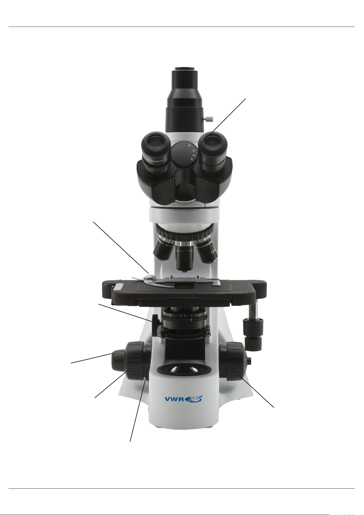
PINZA DE SUJECIÓN DE MUESTRAS
DISTANCIA INTERPUPILAR
MANDO DE REGULACIÓN
DE LA ALTURA DEL CONDENSADOR (4)
MANDO DE ENFOQUE
MICROMÉTRICO
MANDO DE ENFOQUE
MACROMÉTRICO
BLOQUEO DEL MANDO
DE ENFOQUE
REGULACIÓN DE LA
TENSIÓN (5)
62
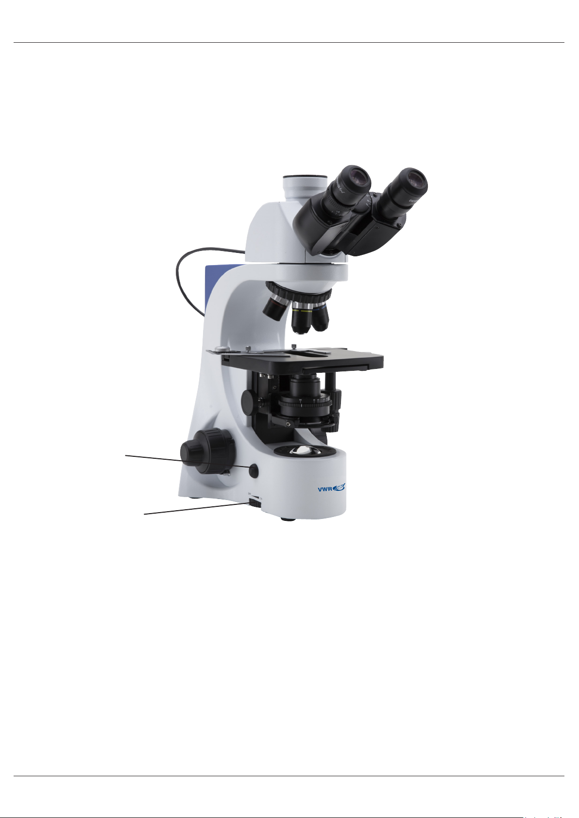
Control Automático De Luz (modelos BL384 P, BL384 PI y BL384 PH)
Los modelos BL384 P y BL384 PI tienen una función especial en el sistema de iluminación denominado
Control Automático de luz (en Inglés Automatic Light Control)
La intensidad de luz se ajusta automáticamente en el microscopio para mantener el mismo nivel de ilumina-
ción seleccionado por el usuario, aunque éste haga cambios en la apertura del diafragam, en el objetivo con
el que trabaje, o varie la opacidad de las muestras, etc.
PU BOTÓN ALC
(CONTROL AUTOMÁTICO
DE LUZ)
MANDO DE AJUSTE
DE INTENSIDAD DE
LUZ
1) Enfocar la muestra con el objetivo que el usuario haya seleccionado, tal y come se describe en el
capítulo anterior.
2) Girar el mando de ajuste de intensidad de luz hasta conseguir el nivel óptimo para la observación.
NOTA: el sistema ALC funciona bien cuando trabaja con una intensidad de luz media-alta sola-
mente. Procure no posicionar la intensidad de luz al mínimo.
3) Presionar el botón ALC ubicado a la izquierda de la base del microscopio.
En estos momentos el sistema ALC (control automático de luz) está funcionando, si abre o cierra la apertura
del diafragma, o cambia de objetivo, el sistema mantendra el mismo nivel de intensidad de luz que haya almacenado en la memoria al presionar el botón ALC.
4) Para cancelar el control automático de luz, presione de nuevo el botón ALC y volverá al sistema manual.
ADVERTENCIA: el sistema ALC no es apto para el uso con contraste de fases.
63

Funcionamiento
Ajustar la observación del cabezal
Aojar los tornillos de ajuste para mover el cabezal hasta obtener una posición cómoda para la observación
antes de jarlo nuevamente.
Colocar una muestra sobre la platina
Fije la preparación o muestra sobre la platina mecánica utilizando la pinza deslizable. Ajuste la muestra o
preparación centrándola sobre la platina moviendo los mandos coaxiales verticales de la misma.
Ajuste de la iluminación
El microscopio incluye un iluminador LED blanco. Antes de conectarlo a la toma de red leer la sección sobre
las precauciones de seguridad. Insertar el jack del transformador en la parte trasera del estativo. Utilizar el
potenciómetro de luz para obtener la intensidad deseada para la observación.
Ajuste de la distancia interpupilar
Mantener con las dos manos la parte izquierda y la derecha del cabezal de observación y regular la distancia
interpupilar girando las dos partes hasta que no se observe un anillo de luz.
El punto blanco que se muestra en el ocular derecho indica la distancia interpupilar justa. Recuerde su
posición para ayudarle con el ajuste en futures observaciones.
Ajuste de la tensión de enfoque
La tensión de los mandos de enfoque viene pre-establecida desde fábrica. Para cambiar la tensión de acuerdo con sus preferencias y comodidad, gire el mando en el sentido de las agujas de reloj para incrementarla.
Demasiada tensión puede dañar el mecanismo de enfoque. Poca tensión causa que la platina descienda por
si sola. Si sucediera esto, gire el mando de ajuste de tensión para incrementarla.
Compensación dióptrica
Girar el mando de enfoque macrométrico para enfocar la muestra utilizando con bajo poder de aumentos.
Regular el mando de enfoque micrométrico hasta obtener una imagen clara y denida observando con el ojo
derecho y girar el anillo de compensación dióptrica situado en el ocular izquierdo hasta obtener una imagen
denida también en el ojo izquierdo. Cuando la imagen esté enfocada, seleccionar el objetivo necesario.
Condensador
Suba o baje el condensador utilizando el mando para obtener una iluminación clara y uniforme de la
muestra.
Para centrar el condensador: cerrar completamente el diafragma iris (1). Usando los tornillos de centrado
del condensador mueva el diafragma en el centro del campo de visión (2). Luego, gradualmente abrir el
diafragma hasta que hasta que vea las tangentes en el borde del campo de visión (3). Si fuera necesario,
puede realizar un ajuste adicional.
En condensador queda centrado cuando los bordes del diafragma iris son tangentes al campo de visión.
Ajustar la apertura numérica
El valor de la apertura numérica (N.A.) del diafragma indica el contraste del sistema de iluminación.
Si el valor N.A. del sistema de iluminación coincide con el del objetivo, obtendrá los mejores resultados en
términos de contraste y calidad de imagen. Para ajustar la apertura numérica del iluminador, ajustar la apertura del diafragma iris. De este modo, Ud. Controla el contraste y la resolución de la imagen. Para muestras
con poco contraste ajuste el iris aproximadamente 75% del valor de la aperture numérica del objetivo.
64

Centrage des anneuax de phase (-PH)
En ce qui concerne les modèles munis d’observation à contraste de phase il est nécessaire d’effectuer le
centrage des anneaux de phase. Sortir un oculaire du tube porte oculaie et enler le télescopé de centrage
dans le porte oculaire vide. Choisir l’objectif 10x en tournat le revolver.
Tourner la tourelle du condenseur jusqu’à ce que vous voyez l’inscription “10”.
Régler la mise au point de l’anneau lumineux que vous observez en dessérant la vis du télescope de cen-
trage. Tournez les deux vis de centrage an de déplacer l’anneau lumineux jusqu’à ce qu’il soit parfaitement
aligné avec l’anneau sombre.
Répéter l’opération avec les autres objectifs (pour vérier que le centrage ait été bien fait).
Les anneaux de phase sont centré quand vous pouvez observez cette image:
Solucionar problemas
Revise la información que aparece en la siguiente tabla.
PROBLEMA CAUSA SOLUCIÓN
LUZ NO SE ENCIENDE Transformador no enchufa-doComprobar que el jack del transfor-
mador 6Vdc está insertado en la parte
trasera del microscopio.
Potenciometro Girar el mando de intensidad de luz
para incrementar la luz.
NO HAY IMAGEN O SE VE NEGRO.
IMAGEN BORROSA O NO TIENE SUFICIENTE CONTRASTE.
El diafragma iris no está
abierto o parcialmente abierto.
Intensidad de luz baja. Girar el potencionmetro de luz.
El objetivo no está centrado
en el eje óptico.
Objetivo o ltro están sucios. Límpielos
La apertura del diafragma
iris no está abierta correctamente.
Condensador posicionado
en altura equivocada
Abra completamente el diafragma iris.
Girar el revolver hasta que uno de
los objetivos esté bien posicionado en
el centro óptico (cuando hace “click”
al girar el revólver, está en su lugar
correcto)
Abrir completamente el diafragma iris.
Girar el mando del condensador hasta
conseguir ver una iluminación uniforme.
65

Reparación y mantenimiento
Condiciones ambientales de trabajo
Se aconseja utilizar éste microscopio en un ambiente limpio y seco; también se deben evitar los impactos. La
temperatura recomendada de trabajo es de 0-40º C y la humedad relativa máxima es de 85% (sin condensación). Si es necesario utilizar un deshumidicador.
Consejos antes y después de la utilización del microscopio
Durante los desplazamientos, mantener el microscopio en posición vertical y prestar mucha atención para
evitar que se caigan los accesorios móviles, por ejemplo los oculares.
Manejar el microscopio con cuidado evitando usar una fuerza mayor de la necesaria.
Evitar reparar el microscopio por su cuenta. Apagar la luz inmediatamente después de haber utilizado el
microscopio, cubrirlo con su correspondiente funda anti-polvo y mantenerlo en un ambiente limpio y seco
Precauciones de seguridad relativas al sistema eléctrico
Antes de conectar el microscopio a la corriente , asegurarse que la tensión de entrada del lugar donde se usa
coincide con la tensión de utilización del microscopio y que el interruptor del iluminador esté en la posición
OFF. El usuario debe consultar las normas de seguridad de su país. El instrumento incluye una etiqueta de
seguridad CE. No obstante éstas pautas el usuario debería utilizar el microscopio en función de sus necesidades pero con un mínimo de responsabilidad y seguridad
Limpieza de las ópticas
Si es necesario limpiar los componentes ópticos, utilizar en primer lugar aire comprimido.
Si no es suciente, limpiar las ópticas con u paño, que no esté deshilachado humedecido con agua y detergente neutro. Y como última opción: humedecer un paño con una mezcla de 3:7 de etanol y éter.
Importante: el etanol y el éter son líquidos altamente inamables. No se deben utilizar cerca de fuentes de
calor, chispas o instrumentación eléctrica. Utilizar en un ambiente bien aireado.
No frotar la supercie de ningún componente óptico con las manos. Las huellas digitales pueden dañar las
ópticas. No desmontar los objetivos o los oculares para intentar limpiarlos.
Para obtener mejores resultados, utilice el kit de limpieza VWR (ver código debajo).
Si fuera necesario enviar el microscopio al fabricante para su mantenimiento, se ruega utilizar el
embalaje original.
66

Accesorios y piezas de repuesto reemplazables
DESCRIPCIÓN CANTIDAD CAT. NO.
Ocular WF10x/20mm 2 630-2000
Ocular WF15x 2 630-2001
Ocular WF20x 2 630-2002
Ocular Micrométrico WF10x/20mm 1 630-2003
Preparación micrometrica 26x76mm, para 1mm 1 630-1650
Ocular 4x/0,10 E-PLAN 1 630-2004
Ocular 10x/0,25 E-PLAN 1 630-2005
Ocular 20x/0,40 E-PLAN 1 630-2006
Ocular 40x/0,65 E-PLAN 1 630-2007
Ocular 60x/0,80 E-PLAN 1 630-2008
Ocular 100x/1,25 E-PLAN (oil) 1 630-2009
Ocular E PLAN IOS 4X 1 630-1639
Ocular E PLAN IOS 10x 1 630-1640
Ocular E PLAN IOS 20x 1 630-1641
Ocular E PLAN IOS 40x 1 630-1642
Ocular E-PLAN IOS 60x 1 630-2049
Ocular E PLAN IOS 100x 1 630-1643
Objetivo PL100x con diafragma iris 1 630-1668
Obj. plano acro. contraste de fase 10x 1 630-2050
Obj. plano acro. contraste de fase 20x 1 630-2051
Obj. plano acro. contraste de fase 40x 1 630-2052
Obj. plano acro. contraste de fase 100x 1 630-2053
Objetivo 10x/0.25 IOS PLAN de contraste de fases 1 630-2054
Objetivo 20x/0.40 IOS PLAN de contraste de fases 1 630-2055
Objetivo 40x/0.65 IOS PLAN de contraste de fases 1 630-2056
Objetivo 100x/1.25 (oil) IOS PLAN de contraste de fases 1 630-2057
Juego completo de contraste de fases con obj. PLAN 10x, 40x,
100x, y condensador campo oscuro para objetivos en seco
Juego completo de contraste de fases con obj. IOS PLAN 10x,
20x, 40x, 100x, y condensador campo oscuro para objetivos en
seco
Set de polarización, solo ltros (para serie 300) 1 630-2285
Platina giratoria para polarización 1 630-2011
Condensador campo oscuro para objetivos en seco 1 630-2060
Adaptador cámara reex para sensor APS-C 1 630-1645
Adaptador para cámara CCD 0,5x 1 630-1644
Platina calefactora con controlador externo y digital de temperatura
1 630-2058
1 630-2059
1 630-2061
67

Servicio técnico
Recursos en Internet
Visite la página de VWR en www.vwr.com para:
• Obtener los contactos del servicio técnico
• Acceder al Catálogo en línea de VWR y obtener información acerca de accesorios y productos relaciona-
dos
• Información adicional sobre productos y ofertas especiales
Contacto Para obtener más información o asistencia técnica póngase en contacto con su representante
local de VWR o visite. www.vwr.com
Garantía
VWR International garantiza que este producto estará libre de defectos de material y fabricación durante
un periodo de 5 años a partir de la fecha de entrega. En el caso de que exista algún defecto, VWR elegirá,
a su elección y corriendo con los gastos, reparar, cambiar o rembolsar el importe de este producto al cliente,
siempre y cuando se devuelva durante el periodo de la garantía. Esta garantía no se aplica si el producto ha
sufrido daños a causa de un accidente, abuso, uso indebido o incorrecto o del desgaste por el uso normal.
Si los servicios de inspección y mantenimiento precisos no se efectúan de acuerdo con las indicaciones de
los manuales o las normativas locales aplicables, la garantía no será válida, salvo si el defecto del producto
no se debe a dicho incumplimiento.
El cliente debe asegurar los productos devueltos contra posibles daños o pérdida. Esta garantía se limita a
los recursos anteriormente mencionados. SE ACUERDA EXPRESAMENTE QUE ESTA GARANTÍA SUSTITUYE A TODAS LAS GARANTÍAS DE IDONEIDAD Y COMERCIALIDAD.
Cumplimiento de leyes y normativas locales
El cliente tiene la responsabilidad de solicitar y conseguir las autorizaciones reglamentarias necesarias o
cualquier otro tipo de autorización necesaria para utilizar el producto en su entorno local. VWR no se responsabiliza de cualquier omisión relacionada o de la no obtención de la autorización necesaria, a menos
que la desestimación se deba a un defecto del producto.
68

Eliminación de residuos
Este equipo está marcado con el símbolo de un contenedor con ruedas tachado para indicar que no debe
desecharse con la basura general.
En su lugar, es su responsabilidad la disposición correcta del equipo a una instalación autorizada para la re-
cogida selectiva y posterior reciclaje. También está bajo su responsabilidad la descontaminación del equipo
en caso de haber usado productos biológicos, químicos y/o contaminación radiológica a n de protegerlos
de peligros para la salud de las personas involucradas en la eliminación y reciclaje de los equipos. Para más
información sobre dónde puede llevar el equipo para su reciclaje, por favor contacte con el representante
VWR de su zona.
De esta manera, Ud. Esta ayudando a conservar los recursos naturales y del medio ambiente, así como
asegurará que su equipo se recicla de una manera que proteja también la salud humana.
Gracias.
69

Alemania
VWR International GmbH
Hilpertstraße 20a
D - 64295 Darmstadt
Freecall: 0800 702 00 07
Fax: 0180 570 22 22*
Email: info@de.vwr.com
*0,14 €/Min. aus d. dt. Festnetz
Australia
VWR International, Pty Ltd.
1/31 Archimedes Place
Murarrie, Queensland, 4172
Tel.: 1300 727 696
Fax: 1300 135 123
Austria
VWR International GmbH
Graumanngasse 7
1150 Wien
Tel.: 01 97 002 0
Fax: 01 97 002 600
E-mail: info@at.vwr.com
Bélgica
VWR International bvba
Researchpark Haasrode 2020
Geldenaaksebaan 464
3001 Leuven
Tel.: 016 385 011
Fax: 016 385 385
E-mail: customerservice@be.vwr.com
China
VWR International China Co., Ltd
Rm.219, 2100 Dongming Road
Pudong New District
Shanghai 200123
Tel.: +86-21-5898 6888
Fax: +86-21-5855 8801
E-mail: info_china@vwr.com
Dinamarca
VWR - Bie & Berntsen
Transformervej 8
2730 Herlev
Tel.: 43 86 87 88
Fax: 43 86 87 90
E-mail: info@dk.vwr.com
España
VWR International Eurolab S.L.
C/ Tecnología 5-17
A-7 Llinars Park
08450 - Llinars del Vallès
Barcelona
Tel.: 902 222 897
Fax: 902 430 657
E-mail: info@es.vwr.com
Finlandia
VWR International Oy
Valimotie 9
00380 Helsinki
Tel.: 09 80 45 51
Fax: 09 80 45 52 00
E-mail: info@fi .vwr.com
Francia
VWR International S.A.S.
Le Périgares – Bâtiment B
201, rue Carnot
94126 Fontenay-sous-Bois cedex
Tel.: 0 825 02 30 30 (0,15 € TTC/min)
Fax: 0 825 02 30 35 (0,15 € TTC/min)
E-mail: info@fr.vwr.com
Hungria
VWR International Kft.
Simon László u. 4.
4034 Debrecen
Tel.: (52) 521-130
Fax: (52) 470-069
E-mail: info@hu.vwr.com
India
VWR Lab Products Private Limited
135/12, Brigade Towers, 2nd Floor
Front wing, Brigade Road,
Bengaluru, India – 560 025
Tel.: +91-80-41117125/26 (Bengaluru)
Tel.: +91-2522-647911/922 (Mumbai)
Fax: +91-80-41117120
E-mail: vwr_india@vwr.com
Irlanda / Irlanda del Norte
VWR International Ltd /
VWR International (Northern Ireland) Ltd
Orion Business Campus
Northwest Business Park
Ballycoolin
Dublin 15
Tel.: 01 88 22 222
Fax: 01 88 22 333
E-mail: sales@ie.vwr.com
Italia
VWR International PBI S.r.l.
Via San Giusto 85
20153 Milano (MI)
Tel.: 02-3320311/02-487791
Fax: 800 152999/02-40090010
E-mail: info@it.vwr.com
Noruega
VWR International AS
Haavard Martinsens vei 30
0978 Oslo
Tel.: 02290
Fax: 815 00 940
E-mail: info@no.vwr.com
Nueva Zelanda
Global Science - A VWR Company
241 Bush Road
Albany 0632, Auckland
Tel.: 0800 734 100
Fax: 0800 999 002
E-mail: sales@globalscience.co.nz
Países Bajos
VWR International B.V.
Postbus 8198
1005 AD Amsterdam
Tel.: 020 4808 400
Fax: 020 4808 480
E-mail: info@nl.vwr.com
Polonia
VWR International Sp. z o.o.
Limbowa 5
80-175 Gdansk
Tel.: 058 32 38 200 do 204
Fax. 058 32 38 205
E-mail: info@pl.vwr.com
Portugal
VWR International -
Material de Laboratório, Lda
Edifício Neopark
Av. Tomás Ribeiro, 43- 3 D
2790-221 Carnaxide
Tel.: 21 3600 770
Fax: 21 3600 798/9
E-mail: info@pt.vwr.com
Reino Unido
VWR International Ltd
Customer Service Centre
Hunter Boulevard - Magna Park
Lutterworth
Leicestershire
LE17 4XN
Tel.: 0800 22 33 44
Fax: 01455 55 85 86
E-mail: uksales@uk.vwr.com
República Checa
VWR International s. r. o.
Veetee Business Park
Pražská 442
CZ - 281 67 Stříbrná Skalice
Tel.: +420 321 570 321
Fax: +420 321 570 320
E-mail: info@cz.vwr.com
Singapur
VWR Singapore Pte Ltd
18 Gul Drive
Singapore 629468
Tel.: +65 6505 0760
Fax: +65 6264 3780
E-mail: sales@sg.vwr.com
Suecia
VWR International AB
Fagerstagatan 18a
163 94 Stockholm
Tel.: 08 621 34 00
Fax: 08 621 34 66
E-mail: kundservice@se.vwr.com
Suiza
VWR International GmbH
Lerzenstrasse 16/18
8953 Dietikon
Tel.: 044 745 13 13
Fax: 044 745 13 10
E-mail: info@ch.vwr.com
Turquía
Pro Lab Laboratuar Teknolojileri Ltd.Şti.
a VWR International Company
Orta Mah. Cemal Gürsel Caddesi
Ördekcioglu Işmerkezi No.32/1
34896 Pendik - Istanbul
Tel.: +90216 598 2900
Fax: +90216 598 2907
Email: info@pro-lab.com.tr
VISITE WWW.VWR.COM PARA
MÁS NOVEDADES Y OFERTAS
ESPECIALES
70

VWR
Microscópio série 384
MANUAL DE INSTRUÇÕES
Model European Catalogue Number
BL384 P 630-1930
TL384 P 630-1931
BL384 PI 630-1932
TL384 PI 630-1933
BL384 PH 630-1934
TL384 PH 630-1935
BL384 PHI 630-2529
TL384 PHI 630-2530
Versão: 7
Emitido: 20, 10, 2014

Endereço Legal do Fabricante
Europa
VWR International bvba
Researchpark Haasrode 2020
Geldenaaksebaan 464
B-3001 Leuven
+ 32 16 385011
http://be.vwr.com
País de origem: ITALIA
Atenção
Informação de Segurança
Conteúdo da embalagem
Desembalagem
Uso Pretendido
Símbolos e convenções
Tabela de Conteúdos
Especicações do produto
Vista geral
Controlo automático da luz (Modelos BL384 P e BL384 PI)
Operação
Ajuste da cabeça de observação
Colocar o espécime na platina
Preparação da lâmpada
Ajuste da distância interpupilar
Foco de ajuste de tensão
Ajuste dióptrico
Condensador
Denição da abertura numérica
Centralização dos anéis de contraste de fase (-PH)
Resolução de problemas
Reparações e manutenção
Acessórios e peças de substituição
Serviço Técnico
Garantia
Conformidade com leis e normas locais
Eliminação do Equipamento
72

Atenção
Este microscópio é um instrumento cientíco de precisão desenhado para durar muitos anos com um mínimo de manutenção. É construído de acordo com os mais altos padrões de qualidade ótica e mecânica para
suportar uso intensivo.
Lembramos que este manual contém informação importante de segurança e manutenção e deverá portanto
estar acessível aos utilizadores do equipamento.
Não nos responsabilizamos por qualquer uso deste instrumento que não esteja de acordo com este manual
Informação de Segurança
Evitar Choque Elétrico
Antes de ligar à corrente, deverá assegurar-se de que a voltagem utilizada na sua região está de acordo cm
a voltagem de operação do equipamento e que o interruptor da iluminação está na posição de desligado.
Os utilizadores deverão cumprir com a regulação de segurança. Este equipamento tem certicação de CE,
no entanto é o utilizador que tem total responsabilidade pelo seu uso em segurança.
Siga as indicações abaixo e leia este manual integralmente para assegurar a operação segura deste equipamento.
Conteúdo da embalagem
DESCRIÇÃO QUANTIDADE
Estátivo del Microscópio com revólver, platina, condensador 1
Tubo da ocular (BL: binocular; TL: trinocular) 1
Objectiva 4x 1
Objectiva10x 1
Objectiva 40x 1
Objectiva 100x 1
Ocular WF10x/20mm 2
Frasco de óleo de imersão 1
Funda para o microscopio 1
Power supply output 6Vdc 1
Desembalagem
O microscópio encontra-se embalado num involucro de esferovite. Remova a ta-cola das pontas do invólucro e levante a metade superior do contentor. Faça este procedimento com cuidado para evitar que alguma
peça ótica (objetivas e oculares) possa cair e danicar-se. Utilizando as duas mãos (uma no braço e outra
na base), retire o microscópio da embalagem e coloque-o numa mesa estável.
Coloque a cabeça de observação no topo do braço e aperte o parafuso de segurança. Insira as oculares nos
tubos oculares.
Ligue o transformador fornecido à corrente elétrica e ligue a cha Jack à parte de trás do microscópio.
73

Uso Pretendido
Apenas para ns de investigação. Não adequado para quaisquer usos terapêutico ou de diagnóstico em
animais ou humanos.
Símbolos e convenções
A tabela seguinte é um glossário ilustrado de símbolos que são utilizados neste manual
ATENÇÃO
Este símbolo indica potencial risco e adverte para que se proceda
com cautela.
Especicações do Produto
Modelo Cabeça Oculares Revólver Objetivas Platina Focagem Iluminação Condensador Fonte de
alimentação
TL384 P
BL384 P
TL384 PI
BL384 PI
BL384 PH
Trinocular,
giratório
360º
inclinado 30
Binocular,
giratório
360º
inclinado 30°
Trinocular,
giratório
360º
inclinado 30
Binocular,
giratório
360º
inclinado 30°
Binocular,
giratório
360º
inclinado 30°
Diâmetro
de campo,
10x/20mm
Diâmetro
de campo,
10x/20mm
Diâmetro
de campo,
10x/20mm
Diâmetro
de campo,
10x/20mm
Diâmetro
de campo,
10x/20mm
Quíntuplo
invertido
Quíntuplo
invertido
Quíntuplo
invertido
Quíntuplo
invertido
Quíntuplo
invertido
160mm
E-PLAN
4X/0.10,
10X/0.25,
40X/0.65
100X/1.25
160mm
E-PLAN
4X/0.10,
10X/0.25,
40X/0.65
100X/1.25
IOS
E-PLAN
4X/0.10,
10X/0.25,
40X/0.65
100X/1.25
IOS
E-PLAN
4X/0.10,
10X/0.25,
40X/0.65
100X/1.25
IOS
E-PLAN
4X/0.10,
10XPH/0.25,
40XPH/0.65,
100XPH/1.25
Mecânica de
camada dupla
160x140mm
amplitude de
deslocação,
X-Y 76x52mm
Mecânica de
camada dupla
160x140mm,
amplitude de
deslocação
X-Y 76x52mm
Mecânica de
camada dupla
216x150mm,
amplitude de
deslocação
X-Y 78x54mm
X belt-drive.
Mecânica de
camada dupla
216x150mm,
amplitude de
deslocação
X-Y 78x54mm
X belt-drive.
Mecânica de
camada dupla
160x140mm,
amplitude de
deslocação
X-Y 76x52mm
Macro e micro
coaxiais.
Macro e micro
coaxiais.
Macro e micro
coaxiais.
Macro e micro
coaxiais.
Macro e micro
coaxiais.
P-LED3 com
regulador de
intensidade
P-LED3 com
regulador de
intensidade.
Controle automático de la luz.
P-LED3 com
regulador de
intensidade
P-LED3 com
regulador de
intensidade.
Controle automático de la luz.
P-LED3 com
regulador de
intensidade.
Controle automático de la luz.
Abbe condenser,
sliding-in, N.A.
1.25 com sistema
de centragem
Abbe condenser,
sliding-in, N.A.
1.25 com sistema
de centragem
Abbe condenser,
sliding-in, N.A.
1.25 com sistema
de centragem
Abbe condenser,
sliding-in, N.A.
1.25 com sistema
de centragem
Condensador
de contraste de
fase (10x/20x,
40x, 100x) para
campo oscuro
(seco) y campo
claro
Alimentador
externo:
Input 100-240Vac
50-60Hz / Output
6Vdc 1A
Alimentador
externo:
Input 100-240Vac
50-60Hz / Output
6Vdc 1A
Alimentador
externo:
Input 100-240Vac
50-60Hz / Output
6Vdc 1A
Alimentador
externo:
Input 100-240Vac
50-60Hz / Output
6Vdc 1A
Alimentador
externo:
Input 100-240Vac
50-60Hz / Output
6Vdc 1A
TL384 PH
BL384
PHI
TL384 PHI
Trinocular,
giratório
360º
inclinado 30
Binocular,
giratório
360º
inclinado 30°
Trinocular,
giratório
360º
inclinado 30
Diâmetro
de campo,
10x/20mm
Diâmetro
de campo,
10x/20mm
Diâmetro
de campo,
10x/20mm
Quíntuplo
invertido
Quíntuplo
invertido
Quíntuplo
invertido
IOS
E-PLAN
4X/0.10,
10XPH/0.25,
40XPH/0.65,
100XPH/1.25
IOS PLAN
10xPh,
20xPh,
40xPh,
100xPh (oil)
IOS PLAN
10xPh,
20xPh,
40xPh,
100xPh (oil)
Mecânica de
camada dupla
160x140mm,
amplitude de
deslocação
X-Y 76x52mm
Mecânica de
camada dupla
216x150mm,
amplitude de
deslocação
X-Y 78x54mm
X belt-drive.
Mecânica de
camada dupla
216x150mm,
amplitude de
deslocação
X-Y 78x54mm
X belt-drive.
74
Macro e micro
coaxiais.
Macro e micro
coaxiais.
Macro e micro
coaxiais.
P-LED3 com
regulador de
intensidade
P-LED3 com
regulador de
intensidade.
Controle automático de la luz.
P-LED3 com
regulador de
intensidade
Condensador
de contraste de
fase (10x/20x,
40x, 100x) para
campo oscuro
(seco) y campo
claro
Condensador
de contraste de
fase (10x/20x,
40x, 100x) para
campo oscuro
(seco) y campo
claro
Condensador
de contraste de
fase (10x/20x,
40x, 100x) para
campo oscuro
(seco) y campo
claro
Alimentador
externo:
Input 100-240Vac
50-60Hz / Output
6Vdc 1A
Alimentador
externo:
Input 100-240Vac
50-60Hz / Output
6Vdc 1A
Alimentador
externo:
Input 100-240Vac
50-60Hz / Output
6Vdc 1A
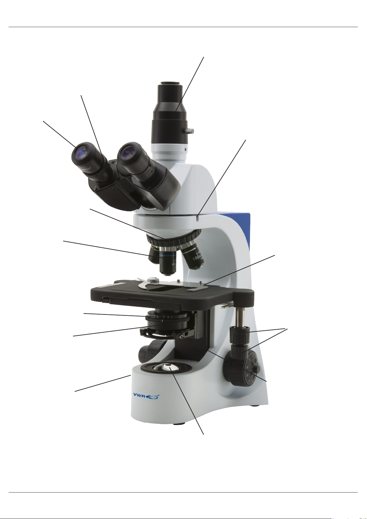
Vista Geral
ANEL DE CORREÇÃO
DIÓPTRICA
OCULARES
REVÓLVER PORTAOBJETIVAS
SAIDA PHOTO / VIDEO
PARAFUSO DE BLOQUEO
DE LA CABEÇA (1)
OBJETIVAS
DIAFRAGMA DE
APERTURA IRIS (3)
CONDENSADOR
REGULADOR DO
BRILLO (A LA ESQ)
PLATINA
PORTAPREPARADOS
MANDOS COAXIALES DE
DESPLAÇAMIENTO DE LA
PLATINA
PARAFUSO DE CENTRAGEM
DEL CONDENSADOR (2)
ILUMINADOR LED
75

PINÇA DE SUJEIÇAO DE AMOSTRAS
DISTANCIA INTERPUPILAR
MANDO DE REGULAÇAO
DE LA ALTURA DEL
CONDENSADOR (4)
MANDO DE FOCAGEM
MICROMÉTRICO
MANDO DE FOCAGEM
MACROMÉTRICO
BLOQUEO DEL MANDO
DE FOCAGEM
REGULAÇAO DE LA
TENSAO (5)
76
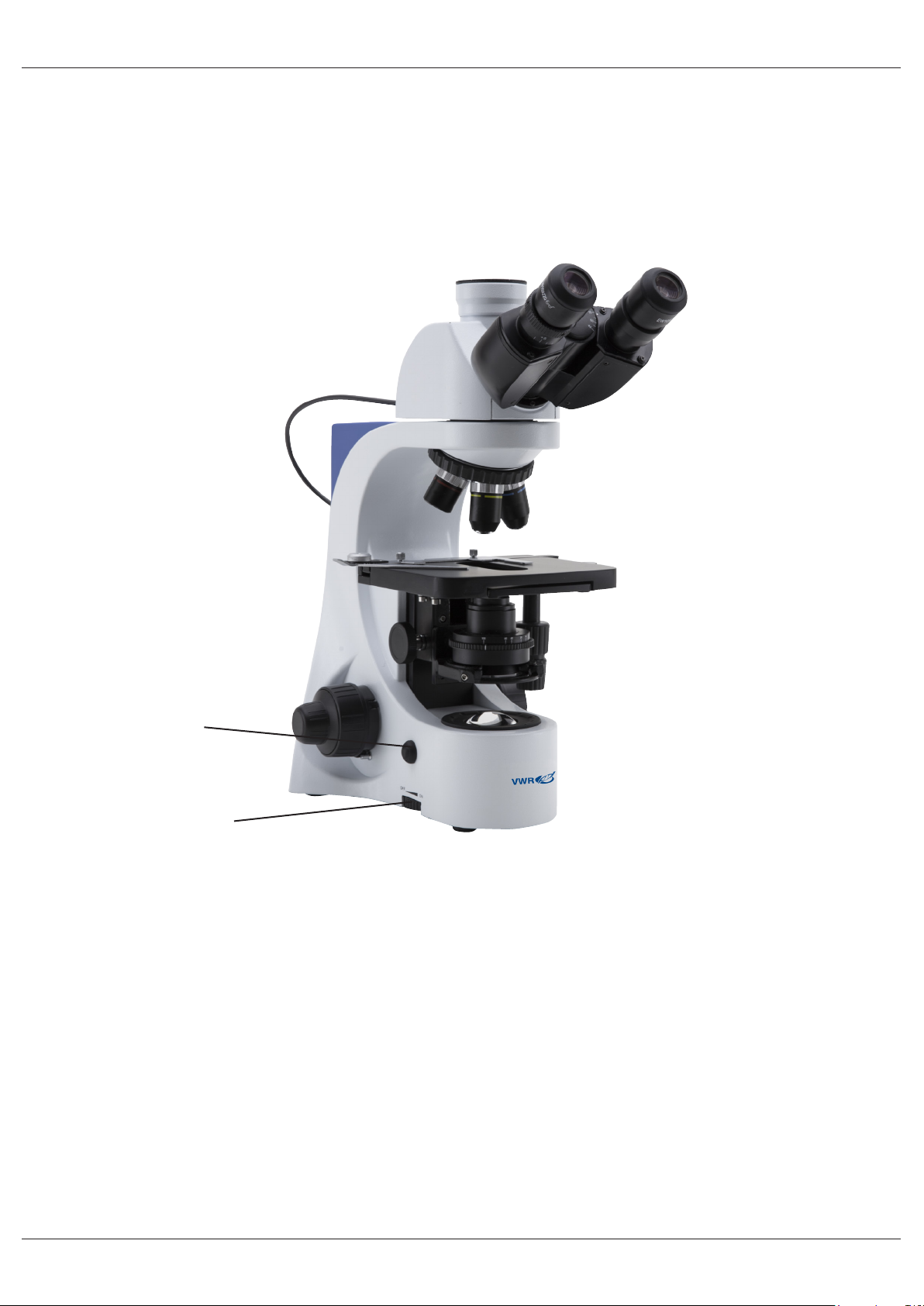
Controlo automático da luz (Modelos BL384 P, BL384 PI e BL384 PH)
Os modelos BL384 P e BL384 PI são dotados de uma função especial denominada “Automatic Light Con-
trol” (Controlo auto mático da luz).
O nível da luz é regulado pelo microscópio para manter o nível desejado pelo usuário , independente-
mente da variação do diafragma de abertura, pela inserção de um objetivo diverso, pela troca da opacidade
da amostra, etc.
BOTÃO ALC
MANÍPULO DE
REGULAÇÃO DA
INTENSIDADE
1) Focalizar a amostra como descrito nos capítulos anteriores utilizando o objetivo desejado.
2) Atuar no manípulo de regulação da intensidade para obter um nível confortável de iluminação.
NOTA: O sistema ALC funciona bem quando se trabalha com uma média de apenas luz de alta
intensidade. Evitar o posicionamento da intensidade da luz a um mínimo.
3) Pressionar o botão ALC localizado na lateral do microscópio.
Agora o sistema ALC está em função: ao abrir ou fechar o diafragma de abertura ou trocar o objetivo, o
sistema tenta manter o nível de luz correspondente ao valor memorizado pressionando o botão ALC.
4) Pressionar novamente a tecla ALC para retornar ao controlo manual da iluminação.
AVISO: O sistema de ALC não é adequado para uso com contraste de fase.
77

Operação
Ajuste da cabeça de observação
Desaperte o parafuso de segurança, coloque a cabeça numa posição confortável para observação e volte a
apertar o parafuso de segurança.
Colocar o espécime na platina
Prenda a preparação na platina mecânica utilizando a pinça lateral. Assegure que o espécime se encontra
centrado na abertura da platina ajustando com os comandos coaxiais.
Preparação da lâmpada
O microscópio está equipado com um potente iluminador de LED branco. Antes de ligar a luz, leia a secção
sobre precauções de segurança com eletricidade. Insira a cha do transformador 6V DC na parte traseira do
microscópio e ligue no interruptor ON/OFF. Rode o regulador de intensidade luminosa até obter uma lumino-
sidade adequada á observação.
Ajuste da distância interpupilar
Segure com as duas mãos as partes direita e esquerda da cabeça de observação, e ajuste a distância interpupilar girando as duas partes até ser visível um círculo de luz.
O ponto branco localizado na ocular direita mostra a distância interpupilar. Memorize este valor para mais
facilmente congurar o microscópio numa próxima utilização.
Foco de ajuste de tensão
A tensão do parafuso micrométrica vem já denida de fábrica. Para alterar a tensão de acordo com as suas
preferências rode o comando de ajuste no sentido dos ponteiros do relógio para aumentar.
Tensão excessiva pode danicar o mecanismo de focagem. Uma tensão muito fraca provoca a descida da
platina por ação da gravidade ou a perda repentina da focagem. Para corrigir esta situação rode o comando
de ajuste para aumentar a tensão.
Ajuste dióptrico
Rode para cima o anel de ajuste dióptrico na ocular direita para alinhar o fundo com o anel graduado. Utilizando uma objetiva de baixa ampliação, rode o parafuso de focagem macrométrica até focar a preparação.
Ajuste a focagem usando o parafuso micrométrico até obter uma imagem nítida e bem denida observando
com o olho direito. Repita a operação com o anel de compensação dióptrica esquerdo para o olho esquerdo.
Quando a imagem estiver focada rode o revólver para a objetiva pretendida.
Condensador
Suba ou desça o condensador através da alavanca para obter uma iluminação limpa e uniforme da amostra.
Para centrar o condensador, feche completamente o diafragma de íris. Usando os parafusos de centralização do condensador, mova o diafragma no centro do campo de visão. Depois, expanda gradualmente o
diafragma até fazer uma tangente com as margens do campo de visão. Se necessário poderá fazer ajustes
adicionais.O condensador encontra-se centrado quando as margens do diafragma zerem tangente com o
campo de visão.
Denição da abertura numérica
O valor da abertura numérica (A.N.) do diafragma é uma indicação do contraste do sistema de iluminação.
Combinar o valor A.N. do sistema de iluminação com o da objetiva assegura melhores resultados em termos
de contraste e qualidade de imagem. Para denir a abertura numérica do iluminador, ajuste a abertura do
diafragma de íris. Desta forma poderá controlar o contraste e resolução da imagem. Para amostras de baixo
contraste, coloque a iris a cerca de 75% do valor da abertura numérica da objetiva.
78
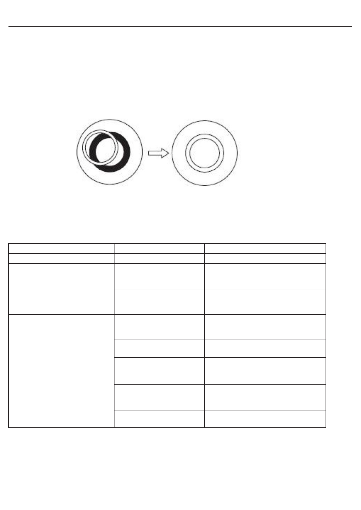
Centralização dos anéis de contraste de fase (-PH)
Para modelos equipados com kit de contraste de fase deverá fazer a centralização dos anéis de contraste
de fase. Remova uma das oculares da cabeça e insira o telescópio de centralização no tubo de ocular vazio.
Coloque a objetiva de 10x no revólver. Gire a torreta do condensador (6) até obter a inscrição “10”.
Desapertando o parafuso de segurança do telescópio de centralização, foque o anel de luz que se tornará
visível. Desaperte os parafusos de segurança das alavancas de centralização (7) dos anéis de fase e des-
loque-os para a frente ou para trás até o círculo de luz brilhante car perfeitamente alinhado com o círculo
escuro. Repita para as outras objetivas (apenas como vericação da correta centralização).
Uma vez centrado com a objetiva de 100x, o condensador estará automaticamente centrado para as outras
objetivas. Os anéis de fase estarão centrados quando conseguir ver uma imagem como ilustrado abaixo:
Resolução de problemas
Reveja a informação na tabela abaixo para tentar solucionar problemas de operação.
PROBLEMA CAUSA SOLUÇÃO
A LUZ NÃO LIGA Fonte de alimentação desli-
gada
Potenciómetro Rode o potenciómetro de ajuste de
NÃO SE CONSEGUE VER IMAGEM OU ESTÁ MUITO ESCURA.
IMAGEM POUCO NÍTIDA,
TURVA OU COM CONTRASTE
INSUFICIENTE
A abertura do diafragma de
iris não está completamente
aberta.
Pouca luminosidade. Rode o potenciómetro de ajuste de
A objetiva não está alinhada
com o eixo ótico
Objetivas e ltros sujos Limpe as partes indicadas
A abertura do diafragma de
iris não está aberta corretamente
Condensador a altura errada Ajuste el mando del condensador ate
Verique se a cha do transformador
6V está bem encaixada na parte trasei-
ra do microscópio
luminosidade e verique que há um
aumento da intensidade luminosa.
Abra completamente a abertura do
diafragma de iris
luminosidade
Rode o revólver até car bem posicio-
nado (até ouvir um click)
Abra completamente a abertura do
diafragma de iris
que consiga uma iluminaçao uniforme
79

Reparações e manutenção
Ambiente de trabalho
Recomenda-se a utilização deste microscópio num ambiente limpo, seco e à prova de choques, com uma
temperatura de 0 – 40ºC e humidade relativa máxima de 85% (não condensado). Utilize um desumidicador
se necessário.
A ter em conta durante e após a utilização do microscópio
Microscópio deve ser mantido em posição vertical quando transportado e com cuidado para que peças des-
tacáveis, tais como as objetivas, não caiam.
Nunca use erradamente ou use força desnecessária ao microscópio.
Nunca tente reparar o microscópio. Após usar, desligue imediatamente a luz, tape o microscópio com a capa
anti-pó incluída e guarde-o em local seco e limpo.
Precauções de Segurança Elétricas
Antes de ligar à corrente, deverá assegurar-se de que a voltagem utilizada na sua região está de acordo cm
a voltagem de operação do equipamento e que o interruptor da iluminação está na posição de desligado.
Os utilizadores deverão cumprir com a regulação de segurança. Este equipamento tem certicação de CE,
no entanto é o utilizador que tem total responsabilidade pelo seu uso em segurança.
Limpeza das partes óticas
Se as partes óticas necessitarem, de limpeza deverá tentar em, primeiro lugar, ar comprimido
Se tal não for suciente, utilize um pano macio com água e detergente suave. E como opção nal, use um
pano humedecido numa mistura 3:7 de etanol e éter
Nota: O etanol e o éter são líquidos altamente inamáveis. Não devem ser utilizados perto de fontes de calor,
faíscas ou equipamentos elétricos. Utilize estes químicos numa sala bem ventilada.
Lembre-se de que nunca deverá limpar as superfícies que qualquer peça ótica com as mãos. As impressões
digitais danicam a ótica. Não desmonte objetivas ou oculares para tentar limpa-las.
Para obtener mejores resultados, utilice el kit de limpieza VWR (ver código debajo).
Se necessitar de enviar o microscópio para o fabricante para reparação, por favor use a embalagem
original.
80

Acessórios e peças de substituição
DESCRIÇÃO QUANTIDADE REF. CAT.
Ocular WF10x/20mm 2 630-2000
Ocular WF15x 2 630-2001
Ocular WF20x 2 630-2002
Ocular micrométrico WF10x/20mm 1 630-2003
Slide micrométrico 26x76mm 1mm 1 630-1650
Ocular 4x/0,10 E-PLAN 1 630-2004
Ocular 10x/0,25 E-PLAN 1 630-2005
Ocular 20x/0,40 E-PLAN 1 630-2006
Ocular 40x/0,65 E-PLAN 1 630-2007
Ocular 60x/0,80 E-PLAN 1 630-2008
Ocular 100x/1,25 E-PLAN (oil) 1 630-2009
Ocular E PLAN IOS 4X 1 630-1639
Ocular E PLAN IOS 10x 1 630-1640
Ocular E PLAN IOS 20x 1 630-1641
Ocular E PLAN IOS 40x 1 630-1642
Ocular E-PLAN IOS 60x 1 630-2049
Ocular E PLAN IOS 100x 1 630-1643
Objetivo diafragma íris PL 100X 1 630-1668
Objetiva 10x PLAN para constraste de fase 1 630-2050
Objetiva 20x PLAN para constraste de fase 1 630-2051
Objetiva 40x PLAN para constraste de fase 1 630-2052
Objetiva 100x PLAN para constraste de fase 1 630-2053
Objetiva 10x/0.25 IOS PLAN para contraste de fase 1 630-2054
Objetiva 20x/0.40 IOS PLAN para contraste de fase 1 630-2055
Objetiva 40x/0.65 IOS PLAN para contraste de fase 1 630-2056
Objetiva 100x/1.25 (oil) IOS PLAN para contraste de fase 1 630-2057
Set Completo de contraste de fase con objetivas PLAN 10x,
40x, 100x, con condensador de campo oscuro para objetivas
secos
Set Completo de contraste de fase con objetivas IOS PLAN
10x, 20x, 40x, 100x, con condensador de campo oscuro para
objetivas seco
Set de polarizaçao, solo ltros (para série 300) 1 630-2285
Platina giratoria para polarizaçao 1 630-2011
Condensador de campo oscuro para objetivas secos 1 630-2060
Adaptador tubo foto emissor para sensor APS-C 1 630-1645
Adaptador câmera CCD 0,5X 1 630-1644
Platina calefactora con control digital de temperatura 1 630-2061
1 630-2058
1 630-2059
81

Serviço Técnico
Recursos online
Visite o site da VWR em www.vwr.com para:
• Informação complete de contactos dos servições técnicos
• Acesso ao catálogo online da VWR’s, e informação acerca de acessórios e produtos relacionados
•Informação adicional em produtos e campanhas especiais
Contacte-nos Para informação adicional ou assistência técnica contacte ou visite o seu distribuidor local.
Garantia
VWR International garante que este produto está isento de defeitos de material e de fabrico por um perío-
do de 5 anos a partir da data de fornecimento. Caso seja detectado um defeito, a VWR irá, a seu crédito e
custos, reparar, substituir ou reembolsar o preço de compra deste produto ao cliente, desde que o produto
seja devolvido durante o período de garantia. Esta garantia não se aplica se o produto tiver sido danicado
devido a acidente, uso indevido, se tiver sido aplicado incorrectamente, ou se os danos resultarem do des-
gaste normal. Se a manutenção necessária e serviços de inspecção não forem efectuados de acordo com
os manuais e com as normas locais, a respectiva garantia torna-se inválida, com a excepção dos casos em
que o defeito do produto não resulta do incumprimento das inspecções e regulamentos.
Os artigos a devolver devem ser protegidos pelo cliente contra potenciais danos ou perda. Esta garantia é
limitada aos recursos acima mencionados. FOI EXPRESSAMENTE ACORDADO QUE A PRESENTE GARANTIA SUBSTITUIRÁ TODAS AS GARANTIAS DE ADEQUAÇÃO, BEM COMO A GARANTIA DE COMERCIALIZAÇÃO.
Conformidade com leis e normas locais
O cliente é responsável pela solicitação e obtenção das autorizações regulamentares necessárias ou outras
autorizações necessários para executar ou usar o Produto no seu local de trabalho. A VWR não assume
responsabilidades por omissões relacionadas com este facto ou pela não obtenção da devida aprovação ou
autorização, a não ser que qualquer recusa se deva a um defeito do produto.
82

Eliminação do Equipamento
Este equipamento está marcado com o símbolo WEEE para indicar que não deverá ser colocado no lixo
comum.
É sua responsabilidade dispor do equipamento e entrega-lo em local autorizado para a separação, recolha
e reciclagem. É também de sua responsabilidade a descontaminação do equipamento em caso de contaminação biológica, química e/o radiológica, assim como proteger de riscos de saúde as pessoas envolvidas na
remoção e reciclagem do equipamento.
Para mais informações de onde entregar o seu equipamento usado, por favor contacte o distribuidor onde
o adquiriu originalmente.
Ao fazer isso está a ajudar a preservar os recursos naturais e ambientais e assegura-se de que o equipamento é reciclado de forma a proteger a saúde humana.
Obrigado
83

Alemanha
VWR International GmbH
Hilpertstraße 20a
D - 64295 Darmstadt
Freecall: 0800 702 00 07
Fax: 0180 570 22 22*
Email: info@de.vwr.com
*0,14 €/Min. aus d. dt. Festnetz
Austrália
VWR International, Pty Ltd.
1/31 Archimedes Place
Murarrie, Queensland, 4172
Tel.: 1300 727 696
Fax: 1300 135 123
Áustria
VWR International GmbH
Graumanngasse 7
1150 Wien
Tel.: 01 97 002 0
Fax: 01 97 002 600
E-mail: info@at.vwr.com
Bélgica
VWR International bvba
Researchpark Haasrode 2020
Geldenaaksebaan 464
3001 Leuven
Tel.: 016 385 011
Fax: 016 385 385
E-mail: customerservice@be.vwr.com
China
VWR International China Co., Ltd
Rm.219, 2100 Dongming Road
Pudong New District
Shanghai 200123
Tel.: +86-21-5898 6888
Fax: +86-21-5855 8801
E-mail: info_china@vwr.com
Dinamarca
VWR - Bie & Berntsen
Transformervej 8
2730 Herlev
Tel.: 43 86 87 88
Fax: 43 86 87 90
E-mail: info@dk.vwr.com
Espanha
VWR International Eurolab S.L.
C/ Tecnología 5-17
A-7 Llinars Park
08450 - Llinars del Vallès
Barcelona
Tel.: 902 222 897
Fax: 902 430 657
E-mail: info@es.vwr.com
Finlândia
VWR International Oy
Valimotie 9
00380 Helsinki
Tel.: 09 80 45 51
Fax: 09 80 45 52 00
E-mail: info@fi .vwr.com
França
VWR International S.A.S.
Le Périgares – Bâtiment B
201, rue Carnot
94126 Fontenay-sous-Bois cedex
Tel.: 0 825 02 30 30 (0,15 € TTC/min)
Fax: 0 825 02 30 35 (0,15 € TTC/min)
E-mail: info@fr.vwr.com
Índia
VWR Lab Products Private Limited
135/12, Brigade Towers, 2nd Floor
Front wing, Brigade Road,
Bengaluru, India – 560 025
Tel.: +91-80-41117125/26 (Bengaluru)
Tel.: +91-2522-647911/922 (Mumbai)
Fax: +91-80-41117120
E-mail: vwr_india@vwr.com
Hungria
VWR International Kft.
Simon László u. 4.
4034 Debrecen
Tel.: (52) 521-130
Fax: (52) 470-069
E-mail: info@hu.vwr.com
Irlanda / Irlanda do Norte
VWR International Ltd /
VWR International (Northern Ireland) Ltd
Orion Business Campus
Northwest Business Park
Ballycoolin
Dublin 15
Tel.: 01 88 22 222
Fax: 01 88 22 333
E-mail: sales@ie.vwr.com
Itália
VWR International PBI S.r.l.
Via San Giusto 85
20153 Milano (MI)
Tel.: 02-3320311/02-487791
Fax: 800-152999/02-40090010
E-mail: info@it.vwr.com
Noruega
VWR International AS
Haavard Martinsens vei 30
0978 Oslo
Tel.: 02290
Fax: 815 00 940
E-mail: info@no.vwr.com
Nova Zelândia
Global Science - A VWR Company
241 Bush Road
Albany 0632, Auckland
Tel.: 0800 734 100
Fax: 0800 999 002
E-mail: sales@globalscience.co.nz
Países Baixos
VWR International B.V.
Postbus 8198
1005 AD Amsterdam
Tel.: 020 4808 400
Fax: 020 4808 480
E-mail: info@nl.vwr.com
Polónia
VWR International Sp. z o.o.
Limbowa 5
80-175 Gdansk
Tel.: 58 32 38 200 do 204
Fax. 58 32 38 205
E-mail: info@pl.vwr.com
Portugal
VWR International - Material de Labo-
ratório, Lda
Edifício Neopark
Av. Tomás Ribeiro, 43- 3 D
2790-221 Carnaxide
Tel.: 21 3600 770
Fax: 21 3600 798/9
E-mail: info@pt.vwr.com
Reino Unido
VWR International Ltd
Customer Service Centre
Hunter Boulevard - Magna Park
Lutterworth
Leicestershire
LE17 4XN
Tel.: 0800 22 33 44
Fax: 01455 55 85 86
E-mail: uksales@uk.vwr.com
República Checa
VWR International s. r. o.
Veetee Business Park
Pražská 442
CZ - 281 67 Stříbrná Skalice
Tel.: +420 321 570 321
Fax: +420 321 570 320
E-mail: info@cz.vwr.com
Singapura
VWR Singapore Pte Ltd
18 Gul Drive
Singapore 629468
Tel.: +65 6505 0760
Fax: +65 6264 3780
E-mail: sales@sg.vwr.com
Suécia
VWR International AB
Fagerstagatan 18a
163 94 Stockholm
Tel.: 08 621 34 00
Fax: 08 621 34 66
E-mail: kundservice@se.vwr.com
Suiça
VWR International GmbH
Lerzenstrasse 16/18
8953 Dietikon
Tel.: 044 745 13 13
Fax: 044 745 13 10
E-mail: info@ch.vwr.com
Turquia
Pro Lab Laboratuar Teknolojileri Ltd.Şti.
a VWR International Company
Orta Mah. Cemal Gürsel Caddesi
Ördekcioglu Işmerkezi No.32/1
34896 Pendik - Istanbul
Tel.: +90216 598 2900
Fax: +90216 598 2907
Email: info@pro-lab.com.tr
VISITE-NOS EM WWW.VWR.COM
PARA CONHECER AS ÚLTIMAS
NOVIDADES, OFERTAS ESPECIAIS
E INFORMAÇÕES DETALHADAS
84
 Loading...