

Page 1

O
PERATOR’S MANUAL
G
LASSWARE
W
ASHERS
Page 2

Page 3

Copyright © 2017 VWR International. All marks herein are used under license.
All brand or product names mentioned may be trademarks or registered trademarks of their respective
companies.
Part Number 100002431
Rev 007, 06/17
Original Instructions
The U.S. English version of this document is the original instructions.
All other languages are a translation of the original instructions.
VWR International
Website
This Glassware Washer Operator’s Manual contains confidential and proprietary information of VWR
International and may be used only by a recipient designated by and for purposes specified by VWR
International.
Reproduction of, dissemination of, modifications to, or the creation of derivative works from this
Glassware Washer Operator’s Manual, by any means and in any form or manner, is expressly prohibited,
except with the prior written permission of VWR International. Permitted copies of this document must
retain all proprietary notices contained in the original.
The information in this document is subject to change without prior notice. Always confirm with VWR
International that you are using the most current version of this document. VWR International is free to
modify any of its products and services, in any manner and at any time, notwithstanding the information
contained in this document.
THE CONTENTS OF THIS DOCUMENT SHALL NOT CONSTITUTE ANY WARRANTY OF ANY KIND,
EITHER EXPRESSED OR IMPLIED, INCLUDING BUT NOT LIMITED TO THE IMPLIED WARRANTIES
OF MERCHANTABILITY AND/OR FITNESS FOR A PARTICULAR PURPOSE OR GIVE RISE TO ANY
LIABILITY OF VWR INTERNATIONAL, ITS AFFILIATES OR ITS SUPPLIERS.
The terms and conditions governing the use of this Glassware Washer Operator’s Manual shall consist of
those set forth in written agreements with VWR International.
Radnor Corporate Center
Building One
Suite 200
PO Box 6660
100 Matsonford Road
Radnor, PA 1987-8600
http://us.vwr.com
Rev 007, 06/17 i
© VWR2017
Page 4

Important Symbols
WARNING! INJURY OR EVEN
DEATH MAY RESULT IF A
RECOMMENDATION MARKED
WITH THIS SYMBOL IS NOT
HEEDED.
CRUSH HAZARD. KEEP HANDS
CLEAR WHEN OPERATING DOOR.
Safety Warnings
Always verify that the electric service and other utilities match the unit’s requirements before
connecting to power.
Always read the instruction manual before operating the washer.
Always wear safety glasses when using glass flasks.
Always practice team lifting when moving heavy equipment.
Always ensure that only an authorized technician services the washer.
Always assume that external and internal parts may be very hot. Utilize personal protective
equipment to avoid burns.
Never clean with solvents. Use mild detergent and water only.
Never operate the unit without all covers in place.
Never use with toxic, corrosive, flammable or organic materials unless special precautions are in
place to prevent injury to personnel or damage to equipment.
ELECTRIC SHOCK DANGER!
USE APPROPRIATE CAUTION
TO AVOID INJURY OR DEATH.
BURN DANGER! POTENTIALLY
HOT SURFACE. USE
APPROPRIATE CAUTION.
DO NOT STORE FLAMMABLE
MATERIALS IN CHAMBER.
WEAR SAFETY GLASSES.
CORROSIVE CHEMICAL. WEAR
SUITABLE GLOVES, SAFETY
GLASSES, AND PROTECTIVE
CLOTHING.
PROPERTY CAUTION! TO PREVENT
DAMAGE TO CHAMBER EQUIPMENT AND/OR LOAD, ADHERE TO
PROCEDURES MARKED BY THIS
SYMBOL.
PRACTICAL OPERATING TIP.
THESE RECOMMENDATIONS
STREAMLINE UNIT OPERATION
AND PREVENT COMMON
OPERATOR ERRORS.
EXPLOSIVE MATERIALS HAZARD!
KEEP OBJECTS AWAY FROM HEAT.
ii Rev 007, 06/17
© VWR 2017
Page 5

Warranty Information
VWR washers are warranted by VWR International to be free of defects in material and workmanship when operated
under normal conditions as specified in the instructions provided in this manual. Please take this opportunity to locate
the serial tag on your new VWR and record the information below for future reference. VWR International also
recommends that you complete and return your unit’s warranty registration card.
Model Number
Serial Number
Part Number
Limited Warranty
VWR International (the “Company”) shall warrant each of its products against defects in material or workmanship for a
period of 24 months from the date of shipment provided that the product is used in a reasonable manner under
appropriate conditions and consistent with the applicable operating instructions.
The obligation of the Company shall be, at its option, to repair or replace, without charge any parts that prove to be
defective within the warranty period, if the purchaser notifies the Company promptly in writing of such defect. No
product shall be returned to the Company without prior approval of the Company.
This limited warranty shall cover the costs of parts and labor to repair or replace all defective product(s) at the Seller’s
factory. For all products installed by the Company and located within the Company service travel areas, this warranty
shall cover transportation charges to ship the product to and from the Company’s factory and/or the costs of travel,
room and board if the Company’s employees conduct repair at the Buyer’s location. In lieu of repair or replacement at
the Company’s factory, the Company may, in its discretion, authorize a third party to perform the repair or replacement
at the Buyer’s location, and at the Company’s sole expense.
The Company shall not be responsible for labor charges payable with respect to persons other than Company
employees. Replacement or repair of parts pursuant to this warranty shall not in any way extend the original warranty
period. The Company shall not be responsible for any unauthorized repairs, replacements or product modifications, nor
will it be responsible for any product failures resulting from such unauthorized repairs, replacements or product
modifications negligently or otherwise made by persons other than Company employees or authorized representatives
of the Company. The buyer shall assume transportation charges to ship the product to and from the Company’s factory
and the costs of travel, room and board if the Company’s employees conduct repair at the Buyer’s location within the
warranty period if the product was not installed by the Company’s and/or is not located within the Company’s service
travel areas.
THE COMPANY DOES NOT MAKE AND EXPRESSLY DISCLAIMS ANY WARRANTY OF MERCHANTABILITY OR
FITNESS FOR A PARTICULAR PURPOSE OR ANY OTHER WARRANTY, EXPRESSED OR IMPLIED, WITH
RESPECT TO THE SALE, INSTALLATION, DESIGN OR USE OF ITS PRODUCTS. ADDITIONALLY, THE
COMPANY SHALL NOT BE LIABLE FOR ANY CONSEQUENTIAL DAMAGES RESULTING FROM THE USE OF OR
ANY DEFECTS IN ITS PRODUCTS.
The Company’s employees are available to provide general advice to customers concerning the use of the Company’s
products; however, oral representations are not warranties with respect to particular products or their uses and may not
be relied upon if they are inconsistent with the relevant product specifications for the items set forth herein.
Notwithstanding the above, the terms and conditions set forth in the Company’s formal sales contracts shall be
controlling and supersede any inconsistent terms contained herein, and any changes to such contracts must be made
in writing and signed by an authorized executive of the Company.
WARNING! THE DISPOSAL AND/OR EMISSION OF SUBSTANCES USED IN CONNECTION WITH
THIS EQUIPMENT MAY BE GOVERNED BY VARIOUS FEDERAL, STATE OR LOCAL
REGULATIONS. ALL USERS OF THIS EQUIPMENT ARE URGED TO BECOME FAMILIAR WITH
ANY REGULATIONS THAT APPLY IN THE USERS AREA CONCERNING THE DUMPING OF
WASTE MATERIALS IN OR UPON WATER, LAND OR AIR AND TO COMPLY WITH SUCH
REGULATIONS.
Rev 007, 06/17 iii
© VWR 2017
Page 6

iv Rev 007, 06/17
© VWR 2017
Page 7

Contents
Important Symbols ............................................................................................................................................... ii
Safety Warnings ................................................................................................................................................... ii
Warranty Information .......................................................................................................................................... iii
Contents ...................................................................................................................... v
Introduction ................................................................................................................. 1
Overview .............................................................................................................................................................. 1
Key Features ................................................................................................................................................... 1
Installation and Startup ............................................................................................... 3
Initial Inspection ................................................................................................................................................... 3
Service Connections ............................................................................................................................................ 4
Required Plumbing Supplies ................................................................................................................................ 4
Dimensional Requirements .................................................................................................................................. 5
Undercounter Washer Site Preparation ............................................................................................................... 5
Water Connections .............................................................................................................................................. 5
Electrical Connection ........................................................................................................................................... 6
Freestanding Washer Site Preparation ................................................................................................................ 6
Approximate Rear Connection Locations ............................................................................................................. 7
Washer Setup ...................................................................................................................................................... 7
Washer Components ................................................................................................ 11
On / Off Power Switch ........................................................................................................................................ 11
Handle Cover ..................................................................................................................................................... 12
Ventilation Port ................................................................................................................................................... 12
Control Panel ..................................................................................................................................................... 12
Internal Components .......................................................................................................................................... 13
Detergent / Neutralizer Dispenser ................................................................................................................. 13
Spray Arms .................................................................................................................................................... 14
Filtration ......................................................................................................................................................... 14
Racks ............................................................................................................................................................ 15
Optional Spindle Racks ................................................................................................................................. 15
Operation .................................................................................................................. 17
Cycle Overview .................................................................................................................................................. 17
Pre-Washes ................................................................................................................................................... 17
Rev 007, 06/17 v
© VWR2017
Page 8

Contents
V
Main Wash .................................................................................................................................................... 17
Rinses ........................................................................................................................................................... 17
Drying ............................................................................................................................................................ 18
Detergent Recommendations ............................................................................................................................ 18
Select Dosage ............................................................................................................................................... 18
Before Starting a Cycle ...................................................................................................................................... 18
Starting a Cycle .................................................................................................................................................. 18
Control Panel ................................................................................................................................................. 19
Selecting a Program ...................................................................................................................................... 20
Heavy Wash “Time Saver” Option ................................................................................................................. 20
Stopping or Changing a Program .................................................................................................................. 20
Option/Set Navigation ........................................................................................................................................ 21
Drying Options ............................................................................................................................................... 21
Delayed Start ................................................................................................................................................. 21
Set Time ........................................................................................................................................................ 21
Start/Stop ...................................................................................................................................................... 22
Pausing a Cycle ................................................................................................................................................. 22
WR
Safety Features ......................................................................................................... 23
Overfill Protection ............................................................................................................................................... 23
Door Switch ........................................................................................................................................................ 23
Maintenance ............................................................................................................. 25
Daily Maintenance ............................................................................................................................................. 25
Coarse Filter .................................................................................................................................................. 25
Fine Filter ...................................................................................................................................................... 25
Reassembling Filters ..................................................................................................................................... 26
Weekly Maintenance .......................................................................................................................................... 26
Reassembling Racks ......................................................................................................................................... 27
Unheated Storage .............................................................................................................................................. 27
Cleaning ............................................................................................................................................................. 28
Appendix A: Troubleshooting .................................................................................... 29
Appendix B: Fault Indicators ..................................................................................... 31
vi Rev 007, 06/17
© VWR 2017
Page 9

Overview
Key Features
Chapter
1
Introduction
VWR glassware washers offer extreme durability with stainless steel chambers, easyto-use touch-based controls, six cycle program selections, selectable wash
temperature, deionized (DI) water final rinsing
saving settings.
Equipped with built-in door dispensers for detergent and liquid neutralizer, all models
are available in the undercounter configuration, as well as freestanding and mobile
configurations. A wide variety of optional specialty baskets and inserts are available to
facilitate washing test tubes, Petri dishes, small graduated cylinders, bottles and other
loads that require special consideration. Most models can also accommodate optional
spindle racks for more effective cleaning of narrow-neck glassware such as volumetric
and Erlenmeyer flasks.
1
and a variety of time- and energy-
Digital microprocessor controller with display.
Five selectable wash cycle settings.
Separate wash and drain pumps.
Optional final deionized water rinses for some cycles.
Triple filtration system to protect plumbing and pumps from broken glass and
debris.
Dual drying fans for optimal drying.
1
Deionized water rinsing is not available on some units.
Rev 007, 06/17 1
© VWR2017
Page 10

Introduction
V
WR
2 Rev 007, 06/17
© VWR 2017
Page 11
Initial Inspection
Your VWR glassware washer was carefully packed and thoroughly inspected before
leaving the factory. However, in the unlikely event that shipping damage has occurred,
retain all packing material and contact your freight carrier immediately.
DO NOT ACCEPT damaged shipments from a carrier without a signed notification of
damages.
Upon receiving your shipment, inspect all contents of your equipment for damage.
Check packing material for small accessory items. Remove all packing material
carefully and inspect for concealed shipping damage. Inspect the inside of the
machine for any visible damage. If concealed damage or loss is discovered, contact
the freight carrier immediately.
paperwork intact until a written report is obtained.
Note: VWR International will cooperate in the matter of collecting your claim, but is not
responsible for the collection or free replacement of the material. When possible, replac ement
parts will be shipped and invoiced to you, making them a part of your claim.
Installation and Startup
2
Keep all contents, packing material and related
Chapter
2
2
“Concealed damage or loss” refers to damage or loss that does not become apparent until the merchandise has been
unpacked and inspected. Should damage or loss be discovered, you may make a written request for inspection by the carrier's
agent within 15 days of the delivery date. You may then file a claim with the freight carrier or VWR International, depending on
the terms of your shipment. If your shipment was “FOB Destination” file your claim with VWR International and include the
inspection report and any other supporting documents. If your shipment was “FOB Shipping Point” file your claim with the
freight carrier and include the inspection report and any other supporting documents.
Rev 007, 06/17 3
© VWR 2017
Page 12

Installation and Startup
V
Service Connections
PROPERTY CAUTION! ONLY QUALIFIED PERSONNEL FAMILIAR WITH LOCAL PLUMBING AND
ELECTRICAL CODES AND ORDINANCES SHOULD INSTALL THE WASHER. FOR A FIRST-TIME
INSTALLATION, ALL SITE PREPARATION WORK MUST BE COMPLETED BEFORE THE
WASHER CAN BE INSTALLED WITH FINAL UTILITY CONNECTIONS. IF THE NEW WASHER
REPLACES AN EXISTING UNIT, VERIFY THAT ALL PLUMBING AND ELECTRICAL
CONNECTIONS ARE PROPERLY SIZED AND LOCATED.
The service connections that you intend to use must meet the following requirements:
Requirement Specification
Tap Water Supply
(All Models)
Deionized Water Supply
(All Models Except H-1105)
WR
Minimum Flow Requirement:
3 gpm (11 lpm) @ 18 – 60 psig (124 – 414 kPa)
Although not required, hot water speeds water heat-up and decreases
cycle time. Hot water supply must not exceed 60 °C (140 °F)
Minimum Flow Requirement:
3 gpm (11 lpm) @ 18 - 60 psig (124 - 414 kPa)
Resistivity 1 M/cm
Although not required, installing a shutoff valve (not supplied) in the
water supply line at a readily accessible location will help facilitate
service of the unit.
Electrical Requirements
(All Models)
120 VAC, 1, 60 Hz, 15 A.
Installation Overvoltage Category II.
Main supply voltage fluctuations not to exceed ±10% of normal voltage.
This product is intended for indoor use in the following
Environmental Conditions
Altitudes up to 6500 ft (2000 m)
Temperatures from 5 to 40 °C (41 to 104 °F)
Maximum relative humidity of 80% for temperatures up to 31 °C (88 °F),
Required Plumbing Supplies
Your unit is supplied with rear-mounted PEX plastic hose with 3/8-inch brass
compression fittings
applicable). Various hose and compression adaptors will be provided for additional
water and plumbing needs. It is recommended that you install a shutoff valve at the
water supply connection. An appropriate fitting for connecting the supplied drain hose
to the drain system is also required.
3
for connection to your facility’s tap and DI water supplies (if
environmental conditions:
decreasing linearly to 50% relative humidity at 40 °C (104 °F).
3
Model UCW-VA00001 uses a compression fitting.
4 Rev 007, 06/17
© VWR 2017
Page 13

V
WR Installation and Startup
Dimensional Requirements
For all units, allow at least 26.5 inches of clearance in front of the unit for door
extension and at least two (2) inches of clearance on each side of the door. Prepare
an installation space or cabinet recess consistent with these and the other dimensions
as specified for your model.
Recommended cabinet recess dimensions for undercounter washers are shown
below.
34-1/2"
(876 mm)
25"
(635 mm)
24-1/8"
(613 mm)
Undercounter Washer Site Preparation
During undercounter washer installation, ensure that the water and electrical services
enter the cabinet recess within the shaded area shown below.
2 to 3-1/2”
(50-90 mm)
7 to 9”
(180-230 mm)
Rev 007, 06/17 5
© VWR 2017
Page 14

Installation and Startup
V
Water Connections
Plan the fitting connections and the route for water supply tubing from the washer to
your water supplies. Drill appropriately sized cabinet entry holes as required, keeping
within the shaded area pictured on the previous page. With the washer outside of the
cabinet recess, feed the water supply tubing through the cabinet hole(s) toward the
water source connectors. Route the unit’s drain hose toward a connection to your
facility’s main drain, but do not make any connections at this time.
For units requiring a DI water connection, use plastic or stainless fittings. Brass fittings
may corrode from DI water and are therefore not recommended.
Electrical Connection
WARNING! THE ELECTRICAL RECEPTACLE MUST BE PROPERLY GROUNDED AND COMPLY
WITH APPLICABLE PORTIONS OF NATIONAL AND LOCAL ELECTRICAL CODES. ALL WASHER
SERVICING SHOULD OCCUR WITH THE POWER CORD DISCONNECTED FROM POWER.
For convenience, the unit is provided with a prewired electrical cable and plug. Locate
or install a code-conforming electrical receptacle within reach of the washer’s supplied
cable. The electrical supply should be a dedicated circuit that is properly grounded
and equipped with an appropriately-sized breaker.
Drill a cabinet entry hole for the power cable. Refer to the image below:
WR
Shutoff
Valve
AC Receptacle
Hole for Power Cable
Your VWR glassware washer should not share a circuit with any other appliances.
Provide a local disconnect or switch to ensure safe maintenance access.
Freestanding Washer Site Preparation
For freestanding units, ensure that the water and electrical service connections have
sufficient slack. Excessive tension in water hoses strains fitting connections and can
cause host leakage and/or breakage.
Position the unit on a firm, level floor. Follow the instructions in the Washer Setup
section of this chapter to level and secure the unit.
6 Rev 007, 06/17
© VWR 2017
Page 15

V
WR Installation and Startup
Approximate Rear Connection Locations
Saddle
Drain Hose
Deionized (DI)
Water Inlet
(All models
except H-1105)
Tap Inlet
Note: Your unit may vary from the
image shown, depending on the
model.
Washer Setup
Your VWR glassware washer must be enclosed on the top and back, and on both
sides. The cabinet enclosure into which undercounter units are installed supplies this
protection. Freestanding and mobile units are wrapped with stainless steel panels.
To install your VWR glassware washer:
1. Connect the washer drain hose to your facility’s main drain, ensuring that the
“high-loop” configuration is preserved (as shown below).
The drain connection must conform to the following requirements:
No part of the drain hose should exceed 35 inches (90 cm) above
the bottom of the washer.
Rev 007, 06/17 7
© VWR 2017
Page 16
Installation and Startup
V
PRACTICAL OPERATING TIP. DRILL AN APPROPRIATELY SIZED CABINET ENTRY HOLE AS
REQUIRED TO REACH THE DRAIN CONNECTION. FEED THE SUPPLIED DRAIN HOSE
THROUGH THE CABINET HOLE TOWARD THE DRAIN CONNECTION AND CONNECT THE
DRAIN HOSE TO YOUR DRAIN.
2. Connect the washer to a tap water supply and tighten all connections
WR
The drain connection must be at least 20 inches (50 cm) above the
bottom of the washer.
The drain hose should extend no more than 10 feet (3 m).
Any joints or fittings must be 3/4-inch (18 mm) ID or larger.
Do not connect the drain hose directly to a floor well or its
equivalent as this could cause a siphoning action that could empty
the machine during cycles. Never connect the drain line to a check
valve.
Do not route the washer drain through a vent or air gap, as this may
impede flow during some drain phases. If the drain cannot be hardpiped, secure the drain hose over an open counter drain or floor
drain instead.
securely. If your unit is equipped with a DI water connection, connect the DI
water supply and tighten all connections securely.
3. Connect the unit to the appropriate electrical supply.
4. Test the unit for leaks before leveling and securing the washer in place.
To test for leaks:
Turn on the electrical power and water supplies.
Close and secure the door.
Select and operate a Daily Wash. This cycle executes both tap
water and DI water rinses (if applicable).
While the cycle is operating, carefully check all water supply and
drain connections to ensure that there are no leaks. Correct any
observed leaks before continuing.
5. Position the unit in its final location. For freestanding and mobile units, secure
the unit by depressing the caster break levers on the unit’s casters.
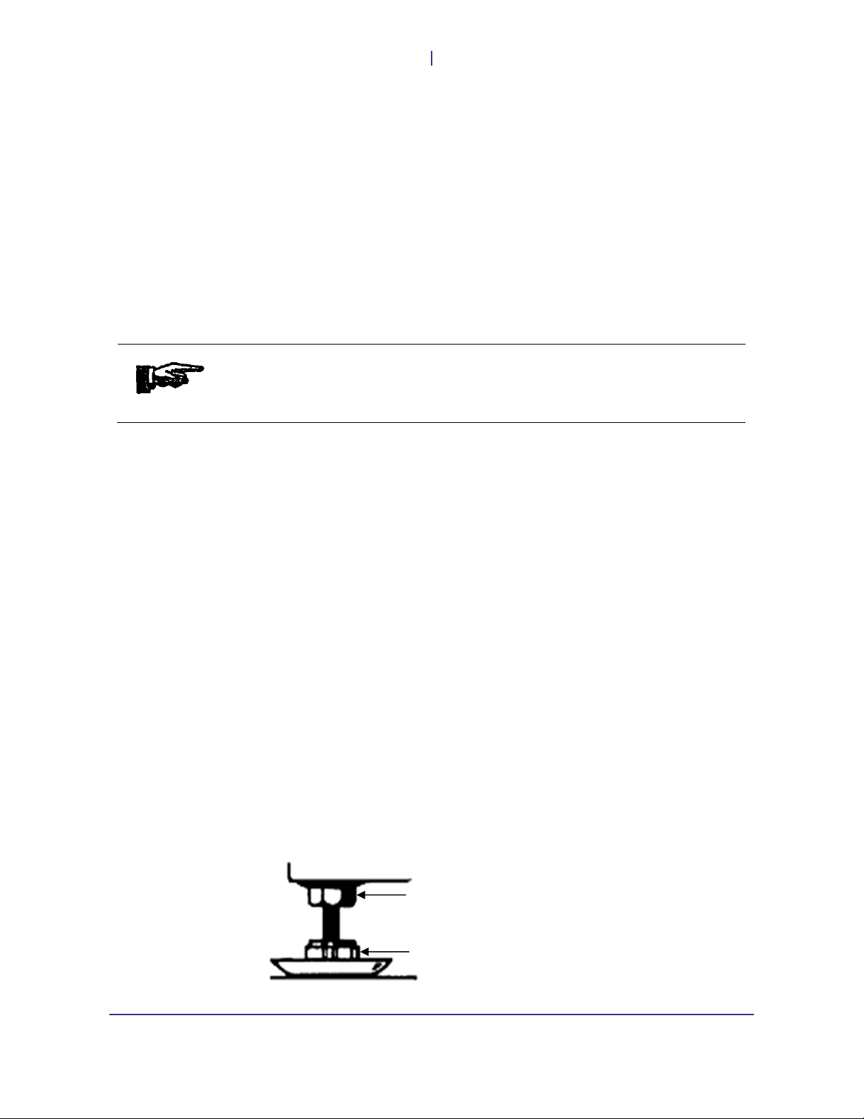
6. Adjust the leveling legs as required.
On undercounter units, leg height may be adjusted by using a 5/8-inch (16
mm) wrench. Any inclination must be ≤ 2 degrees. Use the locking nut to lock
your adjustments
Locking Nut
Foot / Slider
8 Rev 007, 06/17
© VWR 2017
Page 17

V
WR Installation and Startup
7. Secure the washer in its final location.
For undercounter units:
To prevent forward tilting when downward force is applied to the
open door, or when heavily loaded baskets are pulled outward, use
the supplied screws to fasten the washer to the cabinet. Secure the
washer to the cabinet using either option “A” or option “B” (one
screw on each side) as follows:
For freestanding and mobile units:
If your application creates a potential for forward tilting, use the
supplied Tip Guards or similar brackets to secure the washer’s rear
casters to the wall or floor.
Tip Guard
Position for
Casters Only
Mounting
Holes
Tip Guard Position
for Leveling Feet or
Casters
Rev 007, 06/17 9
© VWR 2017
Page 18

Installation and Startup
V
8. Install the optional Toe-Kick Plate, if desired. The Toe-Kick Plate attaches to
WR
the washer’s lower front to optimize appearance, but is not required for
operation of your unit.
To install the Toe-Kick Plate, position each of the two Plate Support Brackets
inward or outward to the desired depth (pulling its catch inward to release the
bracket). Then, simply hook the Toe-Kick Plate on to the front of the bracket.
Catch
Toe-Kick Plate
Plate Support Bracket
10 Rev 007, 06/17
© VWR 2017
Page 19

On / Off Power Switch
Ventilation Port
Note: Your unit may vary from the image shown, depending on the model.
On / Off Power Switch
Chapter
3
Washer Components
Handle Cover
Open your washer’s door to view the On/Off power switch and
control panel. Pushing down on the On/Off power switch will turn the
washer on and off. When on, the unit will energize and the control
panel indicator will illuminate.
On / Off Power Switch Control Panel
Rev 007, 06/17 11
© VWR 2017
Page 20

Washer Components
V
Handle Cover
To unlatch the door, insert your hand, palm up, into the handle cover and pull the latch
forward. When closing the door, push the door closed firmly to reactivate the latch. A
switch within the door handle detects when the door is opened.
Ventilation Port
During the drying phase, fan-circulated air exhausts from this port. Avoid obstructing
this port during washer operation.
Control Panel
VWR glassware washers are equipped with a user-friendly panel of touch-based
controls and indicator lights, located on the upper ledge of the door. Note that
operating the control panel requires a light touch of the fingertip rather than a hard
push.
WR
1. Navigation button < (left)
2. Navigation button > (right)
3. Option/Set
4. Display
5. Rinse Aid Indicator
6. Salt Indicator
4
7. Start/Stop
Note: For descriptions of available cycle programs, please see the Operation section of this
manual (i.e., Chapter 4).
4
Salt indicator functionality not available on all units.
12 Rev 007, 06/17
© VWR 2017
Page 21

V
WR Washer Components
Internal Components
Upper Spray Arm
Lower Spray Arm (All Models)
Coarse Strainer
Filter Screen
Prewash Detergent
Compartment
Detergent Door Latch
Detergent
Compartment Cover
Neutralizer / Rinse
Aid Cover
Main Wash Detergent
Compartment
Rev 007, 06/17 13
© VWR 2017
Page 22

Washer Components
V
Detergent / Neutralizer Dispenser
Spray Arms
During the Pre-Wash, Main Wash and Rinse phases of each cycle, these rotating
nozzles shower the underside of the load with circulating water.
Filtration
Coarse Strainer
This strainer removes large debris items from water circulation. Check and clean it
regularly to prevent obstructions to water flow. The strainer rests inside the Fine Filter
Basket.
Filter Screen
WR
The Detergent Door Latch opens the spring-loaded Detergent Door when
pressed. After detergent filling, snap the door closed.
The Pre-Wash and Main Wash detergent compartments can be filled with
detergent according to preference. During cycles, any detergent loaded into
the Pre-Wash compartment dissolves passively into the chamber early in the
cycle. The Detergent Door later opens automatically at the start of the Main
Wash phase, emptying the Main Wash compartment.
If neutralizer is desired, open the Neutralizer Dispenser latch and pour
neutralizer into the well to fill the dispenser. The dispenser injects a metered
dose of neutralizer into the chamber during the penultimate Rinse phase.
This filter helps remove smaller particles from the water circulation path. Check and
clean it regularly to prevent obstructions to water circulation. The filter is fastened to
the base of the washer chamber by the Fine Filter Basket, which is hand-screwed into
place.
14 Rev 007, 06/17
© VWR 2017
Page 23

V
WR Washer Components
Racks
Lower and upper spray arms dispense tap and deionized5 water upward onto
glassware loaded in standard VWR open racks.
Standard open racks provide ample loading space for glassware, specialty racks,
baskets and inserts.
Optional Spindle Racks
VWR washer models UCW-VA20001, UCW-VA20101, UCW-VA30001,
UCW-VA30101, VSW-VA21001, and VSW-VA22001 can also accept optional spindle
racks, which provide an effective means to thoroughly wash the interiors of narrowneck glassware such as volumetric and Erlenmeyer flasks. Ensure that spindles are
inserted through the deck plates in the forward position.
Use forward position
As illustrated below, optional spindle racks must provide proper “boot sealing” and
therefore cannot be intermixed with standard open racks:
Spray Tube
Flask
Support
Spring Clip
Optional Spindle Racks Optional Tall Spindle Rack
Boot
When using spindle racks, the height of each plastic flask support must be set to
ensure that the spray tube does not touch the bottom of the inverted glassware
positioned above it. Do this by squeezing and then repositioning the spring clip.
5
Deionized water is available on models UCW-VA10001, UCW-VA10101, UCW-VA20001, UCW-VA20101, UCW-VA30001,
UCW-VA30101, VSW-VA11001, VSW-VA21001, and VSW-VA22001 only.
Rev 007, 06/17 15
© VWR 2017
Page 24

Washer Components
V
If your unit is equipped with optional spindle racks, check the rack collar gap on each
rack before using it for the first time and adjust if necessary. The gap should be
approximately the thickness of a postcard.
GAP
WR
RUBBER
BOOT
SET
SCREW
COLLAR
To adjust the gap, loosen the collar’s setscrew and move the collar up or down to
achieve proper gap. Re-tighten the setscrew before using the rack.
16 Rev 007, 06/17
© VWR 2017
Page 25

Cycle Overview
Your VWR glassware washer allows you to select and customize a variety of cycle
phases to design a cycle best suited for your application. In the Main Wash and
Heated Rinse phases, an inline heating element heats water to a programmed
temperature.
PRE-
WASHES
Overall time to complete a cycle varies depending on the cycle and control panel
functions selected, and the facility’s water temperature. Although not required, hot
source water speeds water heat-up and dry time, decreasing overall cycle time.
Note: On some program cycles, not all of the phases are utilized. DI Water Rinse phases do
not apply to models UCW-VA00001 and UCW-VA00101.
Pre-Washes
Operation
6
Cycles then proceed through the following sequence of phases:
MAIN
WASH
TAP WATER
RINSE(S)
OPTIONAL DI
WATER RINSE
Chapter
4
DRYING
PHASE
In Pre-Wash phases, the chamber sump well fills with tap water and the circulation
pump activates to wet down the load from the rotating spray arms and from the
spindles, if equipped with an optional spindle rack.
Main Wash
The chamber fills with tap water, which is heated to the temperature setpoint. At the
start of the Main Wash phase, the detergent compartment cover hinges open to
introduce detergent. The load is bathed with recirculating heated water. The Main
Wash phase concludes by draining all water from the chamber.
Rinses
During each rinse phase, water fills the chamber and then circulates over the load.
The final Rinse phase is heated to the temperature called for by the selected program
and option-button settings. If neutralizer is loaded, it is delivered into the chamber
during the Rinse phase(s). Rinsing concludes by draining all water from the chamber.
6
Heated-Phase durations are determined by the cycle program selected and the required water heat-up time. Therefore, total
cycle time is influenced by the source-water temperature and operator control selections.
Rev 007, 06/17 17
© VWR 2017
Page 26

Safety Features
V
Drying
During the Drying phase, two separate fans circulate and vent chamber air to speed
drying. Although not required, hot source water speeds water heat-up and dry time,
decreasing overall cycle time.
Detergent Recommendations
Use only detergents or wetting agents intended for use in glassware washers.
Note: Do not load detergent or neutralizer into the unit for Rinse cycles.
Select Dosage
Excessive neutralizer/rinse aid can lead to foam buildup. If your water is particularly
soft, you can dilute the rinse aid (e.g., 1 part rinse aid and 1 part water). Too much
neutralizer/rinse aid can cause streaks on glassware, while too little can result in
water stains.
Before Starting a Cycle
8. Open any required tap and/or deionized water supply shut-off valves, and turn
on any switch or circuit breaker supplying AC voltage to the washer.
WR
9. If optional spindle rack use is desired, remove both standard open racks and
10. Choose the basket and insert accessories appropriate for the type load you
11. Load objects with the concave side down to prevent items from protruding into
12. Load the Neutralizer/Rinse Aid Dispenser as desired. Close and latch the
13. Firmly push the washer door closed to latch it securely. Cycles will not begin
Starting a Cycle
14. Turn the washer on by pressing the On/Off power switch. The control panel’s
15. Search for cycle options by using the left and right arrow buttons.
16. After selecting a cycle option, select the desired program type by pressing the
replace them with upper and lower spindle racks, or with one tall spindle rack.
Note: The collar gap must be adjusted before the first use of a spindle rack.
will be washing (e.g., test tube baskets for test tubes).
the path of the spray arm(s).
Detergent Door when done.
until the door is latched.
display and indicators will energize.
control panel’s Option/Set button until the desired program is displayed. To
exit the Option/Set menu, cycle through until the Exit option is displayed;
touch the Option/Set button to select Exit.
17. Depending on which cycle is selected, you will see options to delay the start
of a cycle, set long or short drying times, set a time for a program (only
available in the Time Program selection) or change the temperature to a lower
setting (only available in the Heavy Wash selection).
18 Rev 007, 06/17
© VWR 2017
Page 27

V
WR Basic Operation
18. To begin the cycle, press the Start/Stop button. The section of the control
panel that displays the selected cycle’s time will begin to flash. It will continue
flashing until the door is closed.
19. To stop or cancel an active cycle, gently touch and hold the Start/Stop button
for three seconds.
Control Panel
1. Navigation button < (left)
2. Navigation button > (right)
3. Option/Set
4. Display
5. Rinse Aid Indicator
6. Salt Indicator
7
7. Start/Stop
7
Salt indicator functionality not available on all units.
Rev 007, 06/17 19
© VWR 2017
Page 28

Safety Features
V
Selecting a Program
WR
Use the left and right arrow buttons in addition to the Option/Set button to cycle
through the available programs until the desired program is displayed.
a. Normal Wash. Select for normally soiled loads.
b. Rinse. Select to rinse loaded items that you are not yet ready to wash.
c. Time Program. For lightly to heavily soiled loads, depending on selected
time. Longer time provides for a more thorough wash.
d. Heavy Wash. Select for heavily soiled loads.
e. Daily Wash. Select for daily washing.
Heavy Wash “Time Saver” Option
Heavy Wash is the only cycle selection that allows the user to program the wash at a
different temperature. By selecting the Time Saver option through the Option/Set
menu, the temperature of the wash cycle is reduced to 55 °C (as opposed to the
default 70 °C).
Stopping or Changing a Program
If a program needs to be changed during an active cycle, open the door and press
and hold Start/Stop for three seconds. Add more detergent if the lid on the detergent
dispenser has opened. Then choose a new program, press Start/Stop and close the
door.
20 Rev 007, 06/17
© VWR 2017
Page 29

V
WR Basic Operation
Option/Set Navigation
Press Option/Set and then the left and right navigation buttons to select an option for
a wash cycle. Confirm your selection by pressing Option/Set.
Drying Options
Through the Option/Set menu on a selected cycle, a wash cycle can be programmed
to have either a long or short drying time. This selection determines how long the dual
fans will run after a wash cycle is completed.
Indicator Light
When a drying option is set as Long, the white indicator light on the Right Arrow
Button will light up and stay lit during the duration of the cycle.
Delayed Start
Through the Option/Set menu on a selected cycle, a wash cycle’s start time can be
delayed by up to 24 hours, selected in increments of one hour.
Press the left and right navigation buttons to select the desired amount of time. Press
Start/Stop after a selection has been made. The washer will count down 1 hour at a
time and starts after the selected delay.
When a delay is set, a white indicator light will illuminate on the Option/Set button.
Press and hold Start/Stop for three seconds if you want to cancel the Delayed Start
option.
Indicator Light
Set Time
Select the Time Program by cycling through the menu with the left and right arrow
buttons. Touch the Option/Set button to go into the Set Time screen. This will allow
adjustment to the duration of the cycle.
Cycle through the seven Set Time options with the left and right arrow buttons. Times
will increase in 15 minute increments for the first four selections. After one hour is
reached on the display, times will cycle through 30 minute increments, up to 2:30.
To exit Set Time setup, press the Option/Set button.
Rev 007, 06/17 21
© VWR 2017
Page 30

Safety Features
V
Start/Stop
Use this button to begin or end a cycle. If no cycle is running, pressing Start/Stop will
activate the selected program. To stop an active cycle, press and hold Start/Stop for
three seconds.
Pausing a Cycle
To pause cycle operation, insert your hand, palm up, into the door’s handle cover and
pull the latch. Wait a few moments for spray-arm movement to stop and pull the door
slightly open. To resume the cycle from the point at which it paused, close the door
and ensure that it is securely latched.
Note: If a cycle is terminated (e.g., the door is opened or a power failure occurs), the water
introduction sequence will not reset until the cycle is allowed to run through to the Drying phase
and the drying fan runs. Unless the unit enters the Drying phase, the valve sequence will
continue from where it was terminated, even if the cycle is restarted.
WR
22 Rev 007, 06/17
© VWR 2017
Page 31

Overfill Protection
In the unlikely event that an equipment malfunction causes the chamber to overfill, an
overflow float sensor device automatically activates chamber draining.
Door Switch
The unit is equipped with a door switch that will automatically suspend operation of
the washer if the door is opened during a cycle. The wash cycle will continue from the
point of interruption after the door is closed.
Note: The washer will not start until the door is properly closed.
PRACTICAL OPERATING TIP. SAFE OPERATION REQUIRES KNOWLEDGEABLE OPERATORS.
TO ENSURE SAFE OPERATION, PLEASE FOLLOW THESE RECOMMENDATIONS:
Chapter
5
Safety Features
f. Read all instructions carefully before using the washer.
g. Properly ground the glassware washer prior to operation.
h. Utilize only detergents and neutralizers recommended by
VWR International for us in glassware washers.
i. Before opening the door, always listen for signs of
washer operation and wait for the sounds of rotating
spray arms and circulating water to stop.
j. Do not wash plastic items unless they are marked
“washer safe.” Check with the item’s manufacturer if
unmarked.
k. Remove the door before discarding an old washer.
Rev 007, 06/17 23
© VWR 2017
Page 32

Safety Features
V
WR
24 Rev 007, 06/17
© VWR 2017
Page 33

ALWAYS REMOVE POWER FROM THE UNIT BEFORE PERFORMING MAINTENANCE
PROCEDURES.
ALWAYS NOTIFY VWR INTERNATIONAL SERVICE BEFORE PERFORMING REPAIRS TO A
UNIT THAT IS UNDER WARRANTY. FAILURE TO NOTIFY VWR INTERNATIONAL SERVICE
WILL VOID THE FACTORY WARRANTY.
Daily Maintenance
Inspect and clean the following chamber components daily, or at a frequency
appropriate for your facility’s washer usage and load characteristics.
Coarse Filter
Chapter
6
Maintenance
The coarse filter is a cylindrical sieve that catches larger pieces of debris. To remove
the coarse filter, turn the plastic handle counter-clockwise and lift up.
Fine Filter
The fine filter is a flat mesh sieve that catches smaller pieces of debris during
draining. Regular inspection is important to prevent the accumulation of lime sediment
or other deposits that may clog the mesh of this filter over time. To remove the fine
filter, remove the coarse filter and lift the fine filter up. Clean the filter by gently rubbing
it with a brush or similar device.
Rev 007, 06/17 25
© VWR 2017
Page 34

Maintenance
V
Reassembling Filters
To reassemble the filters, reverse the process used for removal. Replace the fine
mesh filter and insert the coarse filter into position. Turn the plastic handle clockwise
to secure the filters in place.
Weekly Maintenance
Clean exterior washer surfaces with warm soapy water if necessary. On a weekly or
monthly schedule, inspect the Outlet Pump fins and nearby piping for debris. Clean
with a 4-inch (10 cm) pipe cleaner if necessary. The Outlet Pump area is accessible
beneath a removable plug located at the 9 o’clock position in the floor beneath the
Fine Filter Basket.
WR
Examine the holes in the top surface of the Spray Arms and optional spindles, if
equipped, for mineral deposits or clogs. Remove any such blockages with a needle,
wire or other appropriate tool.
Inspect Spray Arms to verify smooth rotation.
If a spray arm is not rotating freely, look for debris or mineral deposits at the arm’s
axle joint. If you have difficulty cleaning the axle in place, remove the spray arm for
closer inspection. To remove the spray arm from its axle, apply quick upward pressure
on the arm while bracing to prevent hitting nearby parts when the arm snaps free.
Clean debris as necessary.
26 Rev 007, 06/17
© VWR 2017
Page 35

V
WR Maintenance
Reassembling Racks
Take care to reassemble racks in the correct configuration if they are disassembled
during cleaning.
The image below illustrates the correct position for reassembling the wheels of the
upper rack.
Wheels on
Upper Studs
(Upper Rack Only)
Wheels on
Upper Studs
(Upper Rack
Only)
Reassembly of Upper Rack
Unheated Storage
Always drain all water from the washer before storing it for any extended period. This
includes any water trapped in the washer’s internal pumps and inlet valves.
Malfunctions caused by component freezing are excluded from warranty coverage.
Rev 007, 06/17 27
© VWR 2017
Page 36

Maintenance
V
Cleaning
The inner chamber of your VWR glassware washer is made of stainless steel and is
typically kept clean through normal use. However, if you have calciferous (hard)
water, lime deposits can form in the washer. In this case, add two tablespoons of citric
acid to the washer detergent compartment and run a normal wash program.
The following table outlines other effective methods for cleaning stainless steel.
PROPERTY CAUTION! ALWAYS USE THE MILDEST CLEANING PROCEDURE THAT WILL DO
THE JOB EFFECTIVELY. RUB IN THE DIRECTION OF POLISHED LINES TO MAXIMIZE
EFFECTIVENESS AND AVOID MARRING THE SURFACE. RINSE THOROUGHLY WITH WATER
AFTER EVERY CLEANING AND WIPE DRY.
Cleaning Required Cleaning Agent8 Application Method9 Effect on Finish
HEAT TINT OR HEAVY
DISCOLORATION
TENACIOUS DEPOSITS,
RUSTY DISCOLORATIONS,
INDUSTRIAL
ATMOSPHERIC STAINS.
HARD WATER SPOTS AND
SCALE.
Penny-Brite or Copper-Brite
Paste Nu-Steel, DuBois
Temp, Tarnite, or Kelox
Revere Stainless Steel
Cleaner, Take-Off, or AC-60
Allen Polish, Steel Bright,
Wyandotte, Bob-O, Zud,
Dubrite, or Prepare Dex
Oakite No. 33, Dilac, Texo
12, Texo N.Y., Flash-Klenz,
Caddy Cleaner, Turco Scale
4368, or Permag 57
Vinegar
Dilac, Oakite No 33, Texo 12,
Texo N.Y.
Use in direction of polish lines
on No. 4 (polished) finish.
Wipe with dry cloth.
Rub with dry cloth or stainless
steel wool.
Apply with damp sponge or
cloth.
Rub with a damp cloth.
Swab and soak with clean
cloth. Allow to stand 15
minutes or more, per
directions on package. Then
rinse and dry.
Swab or wipe with cloth.
Rinse with water and dry.
Swab with cloth or soak. Let
stand 10-15 minutes. Always
follow with neutralizer rise
and dry.
May scratch No. 2 (mil) and
Nos. 7 and 8 (polished)
finishes.
Use in direction of polish
lines on No. 4 (polished)
finish. May scratch No. 2
(mil) and No. 7 and 8
(polished) finishes.
Use in direction of polish
lines on No. 4 (polished)
finish. May scratch No. 2
Use in direction of polish
lines on No. 4 (polished)
finish. May scratch No. 2
(mil) and Nos. 7 and 8
(polished) finishes.
Satisfactory for use on all
finishes.
Satisfactory for use on all
finishes.
Satisfactory for use on all
finishes. Effective on
tenacious deposits or where
scale has built up.
WR
8
Use of proprietary names is only intended to indicate a type of cleaner, and does not constitute any endorsement (nor does
omission of any proprietary name imply its inadequacy). All products should be used in strict accordance with instructions and
warnings on the product package.
9
In all applications, a stainless steel wool, sponge fibrous brush, or pad is recommended. Avoid use of ordinary steel wool or
steel brushes for scouring stainless steel.
28 Rev 007, 06/17
© VWR 2017
Page 37

Appendix A: Troubleshooting
Problems Possible Causes Action
Glassware hazy or not clean.
Stains or film on glassware.
Water remains in washer after
use, or excessive water in sump
area.
Too little water. Check that the water valve is fully
open. Make sure that the water
pressure meets the specification.
Check any strainers in the water
supply line for clogging; clean as
required. Check drain hose.
Incorrect dosage of detergent. Dispense according to the level of
water hardness.
Hard water. If your facility has hard water, try
adding more detergent and/or more
neutralizer.
Wrong detergent. Change detergent as required.
The spray arms rotate poorly or are
not rotating.
Holes on spray arms clogged. Clean as required.
Wrong wash program selected. Heavier programs are longer, and
Incorrect loading of the dishwasher. Try not to place too much tall
Glassware has tipped over during
the wash.
Excessive neutralizer is causing
over-foaming.
Phosphate-free detergent in
combination with hard water.
Too high a temperature and/or too
much detergent can cause etching
on glass.
Too high dosage of rinse aid. Reduce dosage. Try diluting the
Coarse filter clogged. Clean as required.
Outlet pump fins clogged. Clean as required.
Drainage hose is kinked, folded, out
of saddle or extended too long.
Drainage hose is clogged. Clean as required.
Check that spray arms rotate freely
and that load items do not obstruct
movement. Lift off the arms and
clean.
use higher temperatures for dirtier
loads. Use a heavier program better
suited for the load.
glassware in the corners of the
baskets. Make sure washer is not
overloaded and that items are not
blocked from receiving spray.
Load the glassware securely.
Decrease neutralizer metering.
Change detergent.
Wash glassware at a low
temperature and use detergent
sparingly.
rinse aid with water (e.g., 1 part
rinse aid, 1 part water).
Correct as required.
Appendix
A
Rev 007, 06/17 29
© VWR 2017
Page 38

Appendix A: Troubleshooting
V
Problems Possible Causes Action
Washer cycles take too long to
complete.
Washer will not start or cannot
select and begin a cycle.
Marks or discoloration.
Yellowish marks.
Silicon Film.
Glassware does not dry
sufficiently.
Door will not close.
Rattling sound heard during
washing.
Machine will not start.
WR
Tap water not hot enough. Check tap water temperature.
Colder temperatures prolong cycle
time.
Power problem. Check breaker.
Door not completely latched. Push the door firmly to engage the
latch.
Washer is in Delay Start mode. Ensure the Delay Start indicator is
off.
Mineral-rich water. Check water hardness.
Wrong type of detergent. Use correct amount and type of
detergent.
Iron-rich water. Temporary Solution: Pour
approximately 0.5 oz (15 ml) of
citric acid into the Pre-Wash
Detergent Compartment and run
the Heavy program.
Permanent Solution: Install an iron
removal system in the water supply.
Softened hard water. Add additional detergent to the
wash. To improve rinsing, do not
load the machine to full capacity.
Machine is not fully loaded. Load the machine fully.
Rinse aid is out or set for too small
a dosage.
High residual moisture in internal
chamber.
Items incorrectly loaded. Load items with concave side
Standing water in washer. Check drain system and outlet
The baskets are not correctly
placed.
The glassware is not properly
loaded or the spray arms are not
rotating.
You have forgotten to switch on the
main switch.
The door is not closed properly. Check.
The circuit breaker has tripped. Check.
The unit’s rear ETL circuit breaker
has tripped.
The plug is not plugged in. Check.
The water tap is off. Check.
Overfilling/leakage. Call VWR Service at
Fill or increase the amount of rinse
aid.
Open the door slightly once the
program has finished.
down.
pump.
Make sure the baskets are in a
horizontal position. Check that the
basket water connector is aligned
with the spray pipe.
Check that the glassware is loaded
securely. Spin the spray arms to
make sure they rotate.
Check.
Check.
(800) 932-5000
30 Rev 007, 06/17
© VWR 2017
Page 39

Appendix
B
Appendix B: Fault Indicators
If there is an error in the washer, it will make a ringing sound to signal that there is a
fault. The washer will present the fault description on the control panel display. To
view, open the washer door to see the panel on the upper ledge.
Display Description Action
Too much water in the machine.
Water inlet fault.
Valve leakage.
Blocked drain.
Clogged filter.
Note: To remove fault indicators from the display, push the On/Off Power Switch twice to turn it
off and back on again.
Call VWR Service at (800) 932-5000.
Check that the water is on.
Switch off the water tap and call VWR Service
at (800) 932-5000.
See possible causes in Appendix A:
Troubleshooting.
Clean the filters. See the Maintenance chapter
for more information.
Rev 007, 06/17 31
© VWR 2017
Page 40

VWR International
Radnor Corporate Center
100 Matsonford Road
Radnor, PA 19087
http://us.vwr.com
Building One
Suite 200
PO Box 6660
USA
(800) 932-5000
 Loading...