

Page 1

AccuSterilizer™
Table Top Steam Sterilizer
Operation Manual
Series 1130
LT1130X1 • 9/9/02
Serial Number
Model Numbers
Without Printer Voltage With Printer
ST113025 120V ST113035
ST113020-33 220V ST113030-33
Page 2
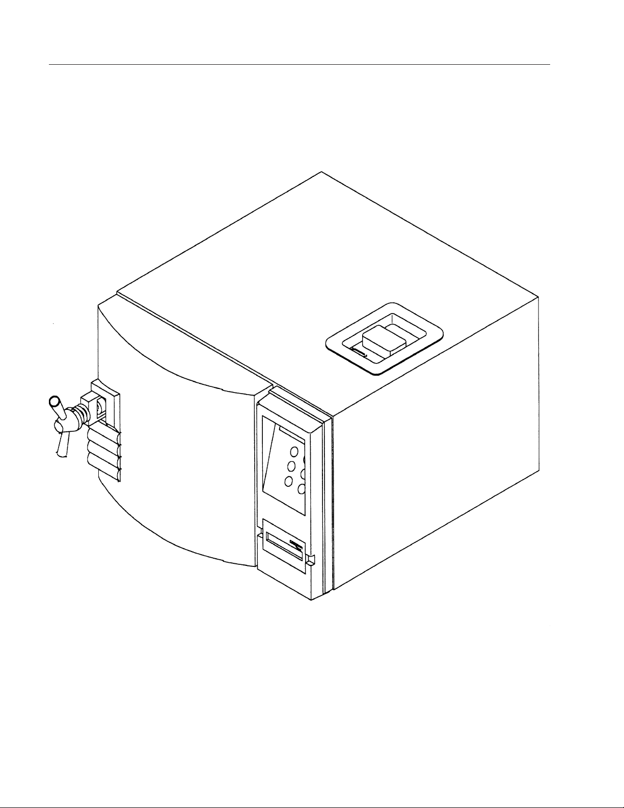
2
AccuSterilizer™ Table Top
Sterilizer
Page 3

3
Table of Contents
Introduction..........................................................................................................................................................5
Safety Information ..............................................................................................................................................6
Warnings ..........................................................................................................................................................6
Specifications ......................................................................................................................................................9
Trays ................................................................................................................................................................9
Dimensions ......................................................................................................................................................9
Shipping Weight ..............................................................................................................................................9
Electrical ..........................................................................................................................................................9
Standards ........................................................................................................................................................9
Reservoir Water ..............................................................................................................................................9
Mounting ..........................................................................................................................................................9
Controls............................................................................................................................................................9
Environmental Conditions ..............................................................................................................................10
Declaration of Conformity ..............................................................................................................................10
Description ........................................................................................................................................................11
Operational Programs ....................................................................................................................................11
Program Summary Chart ..............................................................................................................................12
Controls..........................................................................................................................................................13
Sterilizer Features..........................................................................................................................................14
Installation ........................................................................................................................................................16
Location..........................................................................................................................................................16
Unpacking ......................................................................................................................................................16
Electrical Connections ..................................................................................................................................17
Altitude Adjustment............................................................................................................................................18
Display Parameter Setup ..................................................................................................................................19
Setting Month/Date/Year/Hour/Minute ..........................................................................................................19
Changing Temperature Units ........................................................................................................................20
Changing Pressure Units ..............................................................................................................................21
Changing Printer Mode ..................................................................................................................................22
Sterilization Procedures ....................................................................................................................................23
Materials Appropriate For Steam Sterilization ..............................................................................................23
Instrument Cleaning Prior To Sterilization......................................................................................................24
Preparation of Carbon Steel Instruments ......................................................................................................25
Preparing Items for Sterilization ....................................................................................................................26
Loading the Sterilizer Chamber ....................................................................................................................31
Handling Sterilized Materials ........................................................................................................................32
Recommended Monitoring ................................................................................................................................33
Process Monitoring ........................................................................................................................................33
Biological Indicators ......................................................................................................................................34
Operation ..........................................................................................................................................................36
Initial Startup ..................................................................................................................................................36
Outline of Operation ......................................................................................................................................37
Details of Operation ......................................................................................................................................37
Drying Sterilized Loads ..................................................................................................................................39
Printer................................................................................................................................................................40
Printer Access ..............................................................................................................................................40
Paper Advance Button ..................................................................................................................................40
Page 4

4
Paper Tape Rolls............................................................................................................................................41
Printer Operation............................................................................................................................................41
Printer Tape Description ................................................................................................................................41
Printer Record Storage ..................................................................................................................................42
Special Operating Instructions ..........................................................................................................................44
Emergency Off (Cycle Abort) ........................................................................................................................44
Resetting Automatic OTP ..............................................................................................................................44
Erratic Controls Display or Operation ............................................................................................................45
Power Failure During Sterilizing Cycle ..........................................................................................................45
Problem Solving Chart ......................................................................................................................................46
Maintenance Schedule Chart............................................................................................................................48
Maintenance......................................................................................................................................................49
Daily Maintenance ........................................................................................................................................49
Weekly Maintenance......................................................................................................................................49
Monthly Maintenance ....................................................................................................................................50
Maintenance To Be Done As Required..........................................................................................................52
Changing Door Gasket ..................................................................................................................................53
Figures ..............................................................................................................................................................54
Parts List ..........................................................................................................................................................57
Ordering Procedures ........................................................................................................................................58
Decontamination Statement..............................................................................................................................59
Two Year Limited Warranty ..............................................................................................................................60
TABLE OF CONTENTS
Page 5

5
Introduction
The VWR brand Tabletop steam sterilizer has
been designed for use in medical and dental
offices, university laboratories, clinics, hospitals
and other locations where a variety of materials
require sterilizing.
Your VWR brand AccuSterilizer™ can be used
for wrapped or unwrapped instruments, packs,
liquids, test tubes, petri dishes and media.
The optional thermal printer provides a
permanent record of actual exposure times and
temperatures.
General Usage
Do not use this equipment for any purpose other
than its intended use, described in this manual.
Warning
Do not use this equipment
for any purpose other than
its intended use, described
in this manual.
Do not use the sterilizer to
process volatile substances or materials which
could release toxic or
explosive substances.
Page 6
6
Safety Information
Warnings
1. Do not use this equipment for any purpose
other than its intended use, described in
this manual.
2. Use only self-venting, automatic sealing
stoppers when processing liquids or media.
Use of other stoppers or seals, or lack of
stoppers, will create the possibility of burns
or injury from boiling liquids and exploding
flasks.
3. Refer servicing to qualified personnel.
4. Use caution when opening the sterilizer
door. Stand to the side behind the door and
open door slowly and partially to protect
yourself from escaping steam or boiling
liquids and exploding flasks.
5. Sterilizer and trays will be hot after cycle is
run. Always wear protective gloves and
apron when removing a processed load.
Protective gloves and apron should also be
worn when reloading sterilizer following
previous operation.
6. Do not attempt to open sterilizer door until
the display reads "Cycle Complete".
Pressure within the chamber could cause
the door to open with extreme force,
possibly causing personal injury.
7. Ensure that the sterilizer is cool before
cleaning to avoid burns.
8. Pressurized steam will be discharged when
the relief valve is opened. To prevent
burns, place a steam barrier (such as a
rolled towel) around the opening in the
back of the unit. To prevent burns, wear
gloves or use an extension device if it
becomes necessary to operate the pull
ring.
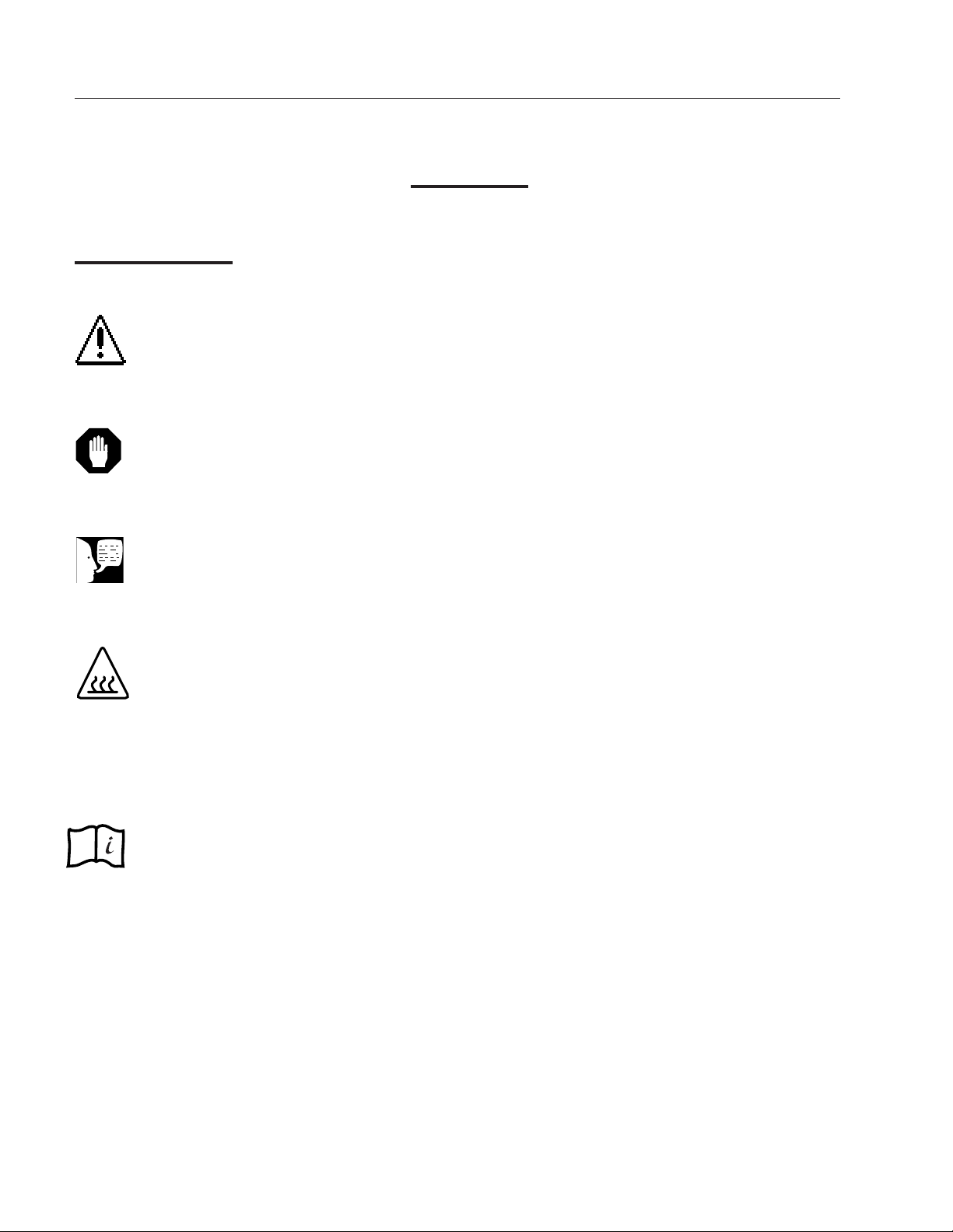
Alert Signals
Note
Notes alert you to pertinent
facts and conditions.
Caution
Cautions alert you to a
possibility of damage to the
equipment.
Warning
Warnings alert you to a
possibility of personal injury.
Hot Surface
Hot surfaces alert you to a
possibility of personal injury
if you come in contact with a
surface during use or for a
period of time after use.
Consult Instructions for Use
This symbol appears on the
product to refer you to the
instruction manual for further
information.
Page 7

7
9. Do not use the sterilizer to process volatile
substances or materials which could
release toxic or explosive substances.
10. Connect only to an electrical circuit of the
appropriate voltage and load rating.
11. Do not overfill reservoir. To avoid slippery
conditions and possible load
recontamination, immediately wipe up all
spillage resulting from overfilling chamber
or reservoir.
12. Do not add water to reservoir while a
sterilization cycle is in process. When the
cycle ends and steam vents back into the
reservoir, a sudden overflow of hot water
could occur, possibly resulting in burns to
personnel.
13. To prevent collection of mineral deposits
and corrosion of chamber components,
use distilled or low quality deionized water
only. Clean chamber after each use if
sterilizing saline solutions.
14. Processing goods at less than recommended time/temperature could result in
unsterile goods.
15. Reprocess your load when the sterilizing
cycle has been terminated prematurely.
The load may not be sterile when the
sterilizing cycle has been terminated
prematurely.
16. Open door slowly at the end of a liquid
sterilization cycle. Do not allow hot bottles
to be jolted. This can cause bottle
explosions. Do not move bottles if any
boiling or bubbling is present.
S
AFETY INFORMATION
Page 8

8
17. Allow bottles to cool before attempting to
move them from sterilizer shelf or tray(s)
to the storage area.
18. If media is processed, bottles and tubes
should contain no more than 3/4 the total
volume of the container. When processing
water bottles and test tubes, the bottles
and tubes should contain no more than
3/4 the total volume of the container.
Chamber should be cleaned daily when
processing media.
19. Keep patients at least six (6) feet away
from the sterilizer when it is in use.
20. Do not operate this sterilizer in the
presence of flammable or explosive
substances (such as anesthetics). A fire or
explosion could occur.
21. Never use a wire brush, steel wool,
abrasive material, or chloride-containing
products to clean door and chamber
assembly.
22. Use a process monitor in every cycle to
ensure exposure to minimum sterilizing
conditions. Use a biological indicator once
a week to verify your sterilization process.
23. Dental handpieces should be run only on
optional cycle at 132°C for 10 minutes.
Check manufacturer's recommendations
for sterilization parameters.
S
AFETY INFORMATION
Page 9
9
Specifications
Trays
Tray Dimensions
Large - 15 1/2" x 9 3/16"
(39.4 x 23.3 cm)
Small - 15 1/2" x 6"
(39.4 x 15.2 cm)
Number of Trays
The sterilizer is supplied with two
trays, 1 large and 1 small, and one
rack.
Dimensions
Capacity
34 Liters (Vessel) (1.2 cubic feet)
7.0 Liters (Reservoir)
Overall Dimensions
W x D x H Inches(cm)
22 7/16" x 24 1/2" x 17"
(57.0 x 62.2 x 43.2)
Chamber (Dia. x Depth)
12" X 18"
(30.5 x 45.7)
Shipping Weight
85 lbs. (38.5 kg)
Electrical
Heater Power
1500 W
Power requirements
120V, 50/60 Hz, 12.5 Amps
220V~, 50/60 Hz, 6.5 Amps
100V, 50/60 Hz, 15 Amps
Standards
ASME
UL/cUL to UL3101-1
Reservoir Water
Distilled or low quality
deionized
Max. 1.5 Megohm/cm
Min. .5 Megohm/cm
Mounting
Benchtop only
Controls
Fixed Cycles
- Liquid
- Packs
- Wrapped
- Unwrapped
Optional Cycle
Note
You can examine
the pressure
vessel rating plate
for the sterilizer
chamber by
opening the panel
on the back cover
of the sterilizer,
then removing the
small plug of
insulation on the
back of the
sterilizer chamber.
Page 10

10
Environmental Conditions
Operating: 4°C - 40°C; 20% - 80% relative
humidity, non-condensing. Installation
Category II (overvoltage) in
accordance with IEC 664. Pollution
Degree 2 in accordance with IEC 664.
Altitude limit: 3,650 meters.
Storage: -25°C - 65°C; 20% - 80% relative
humidity.
Declaration of Conformity
Barnstead|Thermolyne hereby declares under its sole
responsibility that this product conforms with the
technical requirements of the following standards:
EMC: EN50081-1 Generic Emission
Standard; EN 50082-1 Generic
Immunity Standard.
Safety: IEC 1010-1-92 Safety requirements
for electrical equipment for
measurement, control and laboratory
use; Part I: General Requirements
IEC 1010-2-010 Part II: Particular
requirements for laboratory equipment
for the heating of materials
per the provisions of the Electromagnetic
Compatibility Directive 89/336/EEC, as amended by
92/31/EEC and 93/68/EEC, and per the provisions of
the Low Voltage Directive 73/23/EEC, as amended by
93/68/EEC.
The authorized representative located within the
European Community is:
Electrothermal Engineering, Ltd.
419 Sutton Road
Southend On Sea
Essex SS2 5PH
United Kingdom
Copies of the Declaration of Conformity are available
upon request.
S
PECIFICATIONS
Page 11
11
Operational Programs
The sterilizer has four preset cycles which have
been optimized to provide excellent results for most
applications. In addition, there is one optional cycle
that allows you to set your own sterilization
parameters. You access the pre-programmed
cycles by pushing one of the four green fixed-cycle
buttons. The four preset sterilization programs are:
Unwrapped Goods
For unwrapped instruments and items made of
metal, glass or plastic. Parameters: 3 minutes at
135°C.
Wrapped Goods
For wrapped packs of clothes, bandages, pads,
fabrics, rubber tubing and metal instruments.
Parameters: 10 minutes at 135°C.
Liquids
For distilled water, media solutions and other
liquid prepared in closed bottles or flasks.
Parameters: 15 minutes at 121°C.
Packs
For packs of instruments and towels and other
packed goods. Parameters: 30 minutes at 121°C.
If your application requires different sterilization
parameters than the ones set in these programs,
the optional cycle should be selected. See
"Optional Cycle" for details.
Note
The liquid cycle is not
designed for sterilization of
liquids in a clinical
application. Do not prepare
sterile liquids for in vivo
applications with the
Sterilemax system.
Dental handpieces should be
run in the optional cycle at
132°C for 10 minutes. Refer
to manufacturer's
recommendations for contra
indication of sterilization
parameters.
When sterilizing handpieces,
refer to the manufacturer's
specifications on handpieces
for contra indication of
sterilization parameters.
Description
Page 12
12
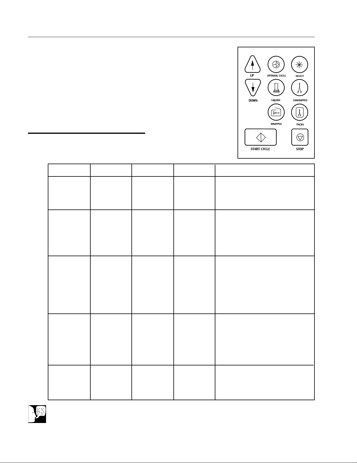
Program Summary Chart
DESCRIPTION
Note
When sterilizing handpieces, refer to the manufacturer's specifications on
handpieces for contra indication of sterilization parameters.
Program
Liquids
Unwrapped
Wrapped
Packs
Optional
Temperature
121°C
(250°F)
135°C
(275°F)
135°C
(275°F)
121°C
(250°F)
User defined
from 100°C to
136°C (212°F
to 277°F)
Time
15 minutes
3 minutes
10 minutes
30 minutes
User defined
from 1 to 99
minutes
Drying Time
None
Default:
15 minutes,
can be set
from 1 to 99
minutes
Default:
15 minutes,
can be set
from 1 to 99
minutes
Default:
15 minutes,
can be set
from 1 to 99
minutes
User defined
from 1 to 99
minutes
Items To Be Sterilized
Distilled water, media solutions, other
liquid prepared in closed bottles or
flasks (not greater than 2 liters). Not
for clinical applications.
Unwrapped instruments; metal glass
and plastic objects. Heat-resistant
rubber tubing which will not be used in
surgical applications. Any other items
for which 135°C for 3 minutes is
appropriate.
Wrapped cloths, bandages, pads, fabrics, loosely wrapped individual instruments, layers of instruments separated by fabric, wrapped trays of loose
instruments, instruments in bags,
heat-resistant rubber tubing. Any
other items for which 135°C for 10
minutes is appropriate.
Packs of towels. Groups of instruments in commercially prepared
packs. Instruments subject to prolonged storage. Surgical gloves
wrapped for sterilization. Any other
items for which 121°C for 30 minutes
is appropriate, except liquids.
Items appropriate to the user defined
parameters. Dental handpieces
should be run in this cycle at 132°C
for 10 minutes.
Page 13
13
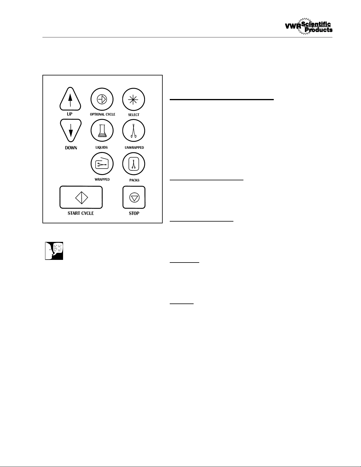
Controls
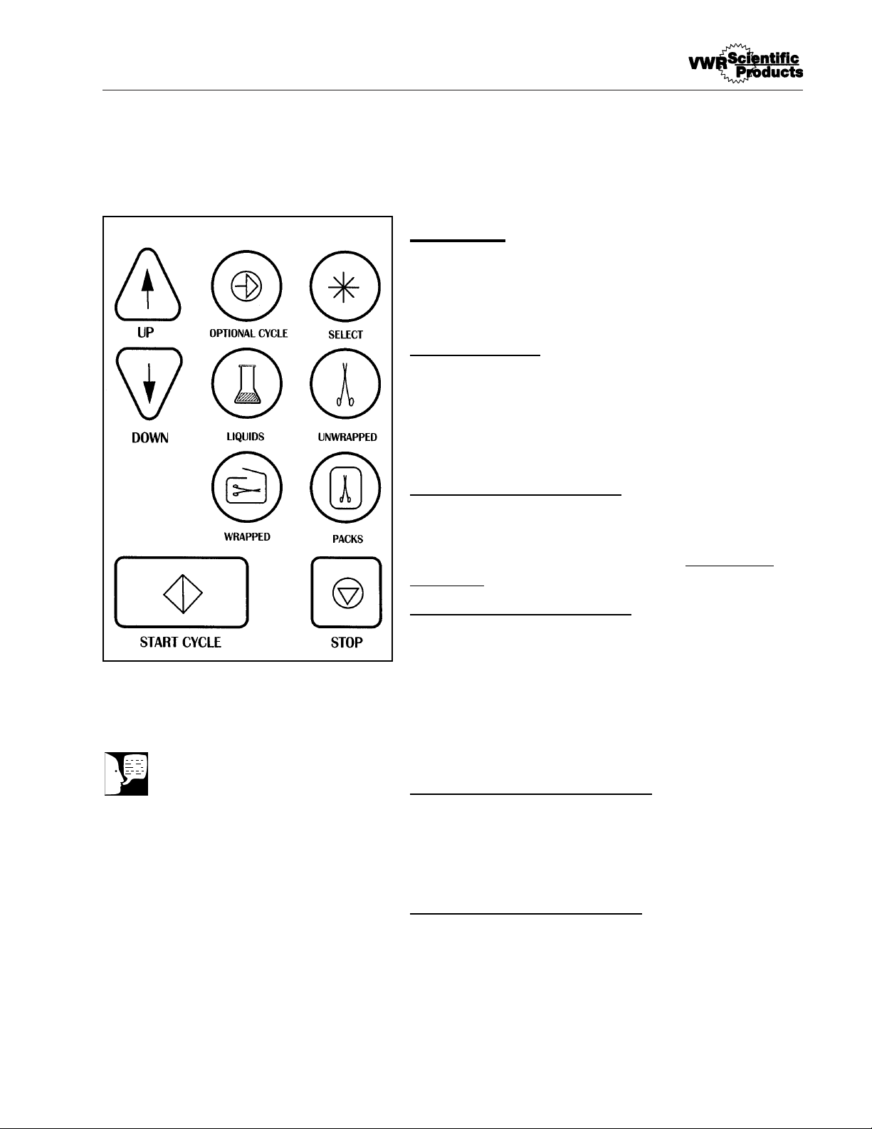
All cycles and programming are selected and set in
using the front touchpad selector buttons.
Power Switch
The Power Switch turns power to the unit on and
off. When you turn the power on, the display will be
set to select a sterilization cycle. It is located under
the right front corner of the sterilizer.
Cycle Buttons (Green)
These buttons allow you to run the preprogrammed
cycles at the touch of a button. See Operational
Programs.
Optional Cycle (Yellow)
This parameter allows you to select different time
and temperature levels for your cycles than those
provided with our preset programs. An optional
cycle can be run as either a liquid or hard goods
cycle. All material run in this cycle must be
validated by the user.
Up/Down Arrows (Yellow)
These allow you to set the time and temperature in
an optional cycle. They are also used for scrolling
through other functions.
Start Cycle (Dark Green)
Pressing the "Start Cycle" Switch activates the
currently selected processing cycle. It is also used
for scrolling through other functions.
D
ESCRIPTION
Note
The "Select" button is used
by VWR service personnel
to adjust the operating
parameters of the sterilizer.
Page 14

14
DESCRIPTION
Stop (Red)
This control is used to terminate any cycle. It is
also used for scrolling through other functions.
Sterilizer Features
Printer
This feature (available on some models) is a
thermal printer that record's each cycle's
performance. See page 40 for more information.
Pressure Monitor
The pressure monitor indicates the pressure inside
the chamber. This monitor's readings can be found
on the display as each cycle is running.
Door Security
While the chamber is under pressure, the door is
held securely closed with three separate locking
systems. First, there is a locking handle that you
must tighten to hold the door fully closed. The
locking handle turns clockwise to close and
counterclockwise to open. Second, there is a
pressure actuated locking pin which automatically
secures the door, preventing it from being
inadvertently opened while there is pressure in the
chamber. Finally, there is a backup catch which will
prevent the door from opening fully even if there is
a small amount of pressure in the chamber. You
release this catch with a lever which is located in
the lower left side of the door. To fully open the
door, pull the door release lever toward you.
Page 15
15
Door Switch
Actuated by the door, the door switch prevents
operation of the sterilizer if the door is not fully
closed.
Pressure Relief Valve
This valve protects the coded vessel from
pressures exceeding the pressure rating of the
vessel. The valve opens and releases steam in the
event that pressure in the vessel exceeds 45 PSIG
(310 kPa). The pressure line is located in the back
of the unit. An access hole is located in the back
panel to allow you to periodically check relief valve
operation.
Reservoir Drain
A drain assembly is provided to empty the
reservoir. The reservoir drain assembly and plug
are located at the lower right of the chamber
opening on the front of the sterilizer (as you face
the unit). The drain assembly attaches to the drain
connector so a hose can be attached for draining
the sterilizer reservoir into a container.
Trays and Tray Rack
A rack for the inside of the sterilizer is provided to
hold the instrument trays. The rack slides out of the
chamber to allow periodic cleaning of the chamber
and rack.
Three large trays and one small tray can be
placed into the rack or the rack can be used with
only one or two trays or no trays. Tall items can be
sterilized by removing both trays and placing the
objects on the bottom surface of the rack. One
large and one small tray are provided with the unit.
See "Loading the Sterilizer Chamber" on page 31
of this manual.
D
ESCRIPTION
Warning
Pressurized steam will be
discharged when the relief
valve is opened. To prevent
burns, wear gloves or use
an extension device if it
becomes necessary to operate the pull ring.
Page 16

16
Installation
Location
For optimum performance of your sterilizer, the
sterilizer should be installed in conformance to the
following parameters:
Surface
For proper operation, the sterilizer must be placed
on a level, heat and water resistant surface. If the
surface is not level, the water in the sterilizer will
be unevenly distributed, possibly resulting in a
sterilizer malfunction. Do not adjust position of the
feet on the sterilizer.
Clearances
Allow at least 3" (75mm) between the sterilizer and
walls on the sides and back for air circulation. Also
allow at least 8" (204mm) between the top of the
sterilizer and any overhanging cabinet above it.
Overhangs should not project more than 8"
(204mm) over the rear of the sterilizer.
Surroundings
If the sterilizer will be operated continuously, locate
it in an area where its steam emissions will not
damage equipment or materials.
Unpacking
Remove the sterilizer carefully and inspect it for
any shipping damage. Do not throw away packing
materials until you inspect the unit.
1. Turn the door handle counterclockwise
until it is completely loose and move the
locking mechanism to the left. Pull on the
Caution
The surface beneath the
sterilizer could reach 100°F
(38°C).
Page 17

17
latch release lever built into the left side of
the sterilizer door and carefully open the
sterilizer door.
2. Remove all packing materials and accessories from the chamber.
3. Remove the trays and rack assembly from
the chamber.
4. Check for any foreign material in the
chamber. Wipe clean with a damp, lintfree cloth if necessary.
Electrical Connections
We recommend that you use a separate
(dedicated) circuit for this sterilizer. Ensure that the
circuit is rated for the load. (See Electrical
Specifications.)
1. Connect power cord to power entry
module on back of unit.
2. Plug power cord into a grounded outlet of
the appropriate voltage and load rating.
Warning
Connect only to an electrical
circuit of the appropriate
voltage and load rating.
Page 18

18
Altitude Adjustment
For proper operation, the sterilizer program
accounts for the altitude in controlling certain
functions. The sterilizer is shipped with a factoryset altitude value suitable for all altitudes up to an
altitude of 1000 feet above sea level. If your
altitude is above 1000 feet above sea level, you will
need to enter a new value for the altitude adjustment. To change the altitude adjustment value:
1. At the "Select Cycle" screen, press the
"Select" key and then the up arrow key.
The sterilizer will display a "Configuration
Info" screen, then it will automatically
change to displaying the "Change Time"
screen.
2. At the "Change Time" screen, press the
"Select" key and then the "Liquids" key.
3. At the "Altitude Adjustment" screen, press
the up arrow to select "Yes".
4. At the "Current Altitude" screen, press the
up and down arrows to set the value for
your location's altitude to the nearest one
hundred feet.
5. After you have set your altitude value,
press the "Start" key to return to the
"Select Cycle" screen.
Page 19

19
Setting Month/Date/Year/Hour/
Minute
To set the current date and time:
1. From the "Select Cycle" screen, press the
"Select" key and then the up arrow key.
2. Wait for the sterilizer to display the
"Change Time" Screen. Press the up
arrow key to select "Yes."
3. At the "Set Current Month" screen, press
the up or down arrow key to set the
current month. Press the "Start" key when
the current month is set.
4. At the "Set Current Date" screen, press
the up or down arrow key to set the
current date. Press the "Start" key when
the current date is set.
5. At the "Set Current Year" screen, press
the up or down arrow key to set the
current year's final two digits. Press the
"Start" key when the current year is set.
6. At the "Change Hour" screen, press the
up or down arrow key to set the current
twenty-four hour clock hour. Press the
"Start" key when the current hour is set.
7. At the "Change Minute" screen, press the
up or down arrow key to set the current
minute. Press the "Start" key when the
current minute is set.
8. At the "Change Temperature Units"
screen, press the down arrow key to
select "No."
Display Parameter Setup
Note
Sterilemax sterilizers are
shipped with the display
units set as follows:
120 volt units - °C, PSI
100 volt units - °C, KPA
240 V~ - °C, BAR
If your unit is not set to these
factory settings or if you
require other settings, refer
to "Changing Temperature
Units" and "Changing
Pressure Units" to set the
units to your requirements.
Note
If you desire to change the
temperature units, press the
up arrow to select "Yes",
then refer to "Changing
Temperature Units."
Page 20

20
9. At the "Change Pressure Units" screen,
press the down arrow key to select "No"
and return to the "Select Cycle" screen, if
a printer is not attached. If the sterilizer
has a printer, the DOWN ARROW key will
go to the "Change Printer Mode" screen.
10. At the "Change Printer Mode" screen,
press DOWN ARROW key to select "NO"
and return to the "Select Cycle" screen.
Changing Temperature Units
To change the units in which the chamber
temperature is displayed on the digital display and
printer tape (°C or °F):
1. From the "Select Cycle" screen, press the
"Select" key and then the up arrow key.
2. Wait for the sterilizer to display the
"Change Time" Screen. Press the down
arrow key to select "No."
3. The sterilizer will then display the "Change
Temperature" screen. Press the up arrow
key to select "Yes."
4. At the "Temperature Units" screen, press
the up arrow key to toggle between °C
and °F.
5. After you have selected your desired
temperature units, press the "Start" key.
6. At the "Change Pressure Units" screen,
press the DOWN ARROW KEY to select
"NO" and return to the "Select Cycle"
screen.
D
ISPLAY PARAMETER SETUP
Note
If you desire to change the
pressure units, press the up
arrow to select "Yes", then
refer to "Changing Pressure
Units."
Note
If you desire to change the
pressure units, press the up
arrow to select "Yes", then
refer to "Changing Pressure
Units."
Note
If you desire to change the
pressure units press the UP
ARROW to select "YES", then
refer to "Change Printer Mode."
Page 21

21
Changing Pressure Units
To change the units in which the chamber pressure
is displayed on the digital display and the printer
tape (PSI, BAR or KPA):
1. From the "Select Cycle" screen, press the
"Select" key and then the up arrow key.
2. Wait for the sterilizer to display the
"Change Time" Screen. Press the down
arrow key to select "No."
3. The sterilizer will then display the "Change
Temperature" screen. Press the down
arrow key to select "No."
4. At the "Change Pressure Units" screen,
press the up arrow key to select "Yes."
5. At the "Pressure Units" screen, press the
up arrow to cycle between the three available units.
6. When you have selected your desired
pressure units, press the "Start" key to
return to the "Select Cycle" screen, if a
printer is not attached. If the sterilizer has
a printer, at the "Change Printer Mode"
screen, press the DOWN ARROW key to
select "NO" and return to the "Select
Cycle" screen.
D
ISPLAY PARAMETER SETUP
Page 22

22
Changing Printer Mode
This display can only be entered if the sterilizer has
a printer. To change the mode of use for attached
printers from USED to UNUSED:
1. From the "Select Cycle" screen, press the
"Select" key and then the UP ARROW
key.
2. Wait for the "Change Time" screen. Press
the DOWN ARROW key to select "NO."
3. The sterilizer will then display the "Change
Temperature" screen. Press the DOWN
ARROW key to select "NO."
4. At the "Change Pressure Units" screen,
press the DOWN ARROW key to select
"NO."
5. At the "Change Printer Mode" screen,
press the UP ARROW to select "YES."
6. At the "Printer Mode" screen, press the
UP ARROW to toggle between the available modes.
7. When you have selected your desired
mode of operation, press the "Start" key to
return to the "Select Cycle" screen—
printer will print one line showing the
current mode setting.
D
ISPLAY PROCEDURE SETUP
Page 23
23
Sterilization Procedures
Materials Appropriate For Steam
Sterilization
• Straight stainless steel instruments
• Surgical stainless steel hinged
instruments
• Pouches of instruments
• Carbon steel instruments (see special
preparation instructions)
• Air powered instruments made to be
autoclaved
• Needles
• Syringes
• Treatment trays
• Heat resistant plastic items
• Rubber gloves
• Heat resistant rubber tubing
• Heat resistant rubber sheeting
• Glass slabs and beakers
• Gauze
• Sutures
• Linen packs
• Liquids, non-clinical
• Other heat-resistant, immersible items
Always check with the manufacturer of your
supplies for specific instructions for sterilization.
Warning
Do not attempt to sterilize
volatile or toxic substances.
Serious injury or death could
result.
Caution
Do not attempt to sterilize
any object composed of
materials which cannot
withstand high temperatures
(135°C or greater).
Page 24
24
Instrument Cleaning Prior To
Sterilization
Transport soiled instruments to your cleanup area
on a tray. Sort out any instruments unsuitable for
sterilization (see list on page 21).
Follow manufacturer's recommendations for
cleaning and preparing any particular item.
In the absence of manufacturer's specific
instructions, clean instruments as follows:
1. Rinse instruments thoroughly with a hard
stream of water to remove debris.
2. Sort instruments by their metallic
composition. Do not mix instruments of
different metals, as instrument damage will
result.
3. Using either a fresh solution of detergent
and distilled water or a germicide solution,
wash instruments in an ultrasonic cleaner
for five to ten minutes. Clean all
instruments in an open position.
Use a detergent or germicide with a
neutral pH (7) specifically designed for use
in an ultrasonic cleaner.
Use new ultrasonic cleaning solution each
day.
4. After cleaning, rinse instruments
thoroughly in distilled or deionized water.
Inspect to ensure that all debris has been
removed. Repeat cleaning as necessary.
If distilled or deionized water is unavailable
and instruments are rinsed in tap water
instead, all instruments should be dried
before sterilizing to prevent staining.
S
TERILIZATION PROCEDURES
Warning
Thoroughly clean instruments before placing them
in the sterilizer. Sterilizing
items contaminated with
blood or debris will impede
sterilization and may result
in unsterile instruments,
which may cause personal
injury or death.
Warning
Always wear protective
gloves when handling soiled
instruments to protect
yourself from the possibility
of serious infection. Clean
gloved hands with a
germicidal cleaner when
finished handling soiled
instruments.
Caution
Sterilizing items
contaminated with blood or
debris may cause staining or
damage to the instruments
or the sterilizer.
Caution
Use of soaking solutions
containing phenols or
quaternary ammonium
compounds may cause
corrosion of the instruments,
trays and the stainless steel
chamber.
Page 25

25
5. Refer to manufacturer's recommendations
for lubricating instruments after ultrasonic
cleaning. Use a silicon lubricant which will
not interfere with sterilization.
Preparation of Carbon Steel
Instruments
Carbon steel instruments must be carefully
prepared prior to sterilization to prevent rusting.
After cleaning according to the manufacturer's
recommendations or the methods presented in
Instrument Cleaning Prior To Sterilization,
prepare carbon steel instruments as follows:
1. Prepare a 2% solution of sodium nitrate in
water (approximately one table spoon in a
quart of water). Completely immerse the
instruments in the solution and allow them
to soak for three minutes.
2. Remove the instruments and package
them for sterilization or place on trays if
sterilizing unwrapped. Do not rinse or
wipe instruments prior to sterilization.
S
TERILIZATION PROCEDURES
Note
Do not place carbon steel
instruments directly onto
stainless steel trays. Place
an unbleached towel or
paper wrap on the tray and
place the instruments on the
towel or paper.
When wrapping instruments
for sterilization, use a
material which promotes
drying.
Page 26
26
Preparing Items for Sterilization
General Preparation Guidelines
1. Clean items thoroughly before placing
them in the sterilizer. Follow good
laboratory or medical procedures for
cleaning and decontamination of items.
2. Place absorbent paper or linen towel in
the bottom of trays before use.
3. Unwrapped goods should only be
processed on trays. Do not place items on
the rack or the bottom of the sterilizer.
4. Liquids must not exceed 75% of capacity
of flask. Use self-venting caps.
5. Open all hinged instruments.
6. Remove the covers from empty
containers. Stand the containers and
covers on their sides.
7. Turn curved vessels upside down so no
water will collect in the vessel.
8. Place all sharps (knives, scissors, etc.) so
that they do not touch during sterilization.
Cotton or gauze may be used to isolate
and protect the sharp edges and the
smaller instruments.
9. Disassemble syringes if possible.
10. Do not plug syringes or needles.
S
TERILIZATION PROCEDURES
Warning
Do not overload the trays.
Overloading trays may result
in inadequate sterilization
and unsterile instruments.
Warning
Monitor the sterilization
process with process
monitors and biological
indicators as described in
Recommended Monitoring
(p. 31).
Caution
Do not mix different metals
in the same pack or
wrapping or loose on the
same tray. Instrument
damage will result.
Page 27
27
Items to be Sterilized Loose and
Unwrapped
Items to be sterilized loose and unwrapped should
be distributed in a single layer on the bottom of a
lined, perforated tray. Do not overload tray; allow
space around instruments for steam circulation.
Metal and glass canisters and containers should
be placed upside down on a perforated tray. Make
sure containers are placed so that they will drain, or
they will not dry sufficiently to ensure sterilization.
S
TERILIZATION PROCEDURES
Warning
Unwrapped items cannot be
considered sterile once
removed from the sterilizer
chamber.
Do not overload the trays.
Overloading trays may result
in inadequate sterilization
and unsterile instruments.
Note
Unwrapped trays are used
for sterilizing nonsurgical
instruments, canisters and
other items to prevent
transmitting infectious
disease.
Appropriate Wrapping Materials for Steam
Sterilization (Partial List)
Muslin (2 layers), Nylon bagging material,
Commerical autoclave paper (must be as
permeable as muslin), Permeable paper and plastic bags, Cloth or paper-covered trays.
Materials Innappropriate for Wrapping for
Steam Sterilization (Partial List)
Canvas, Impermeable plastics, Aluminum foil,
Sealed jars, canisters or tubes.
Page 28
28
Items to be Sterilized Wrapped
Cleaned items may be wrapped individually in
autoclave paper or placed in commercially
prepared autoclave bags. Do not wrap tightly. Seal
with autoclave tape or heat sealer.
Cleaned items may also be sterilized as a group
of instruments wrapped together. You may desire to
wrap a group of similar instruments together, or
you may desire to wrap together the instruments
needed for a particular procedure. Wrap the
instruments loosely in 2 to 4 layers of autoclave
paper or muslin or place them in autoclave bags.
Seal with autoclave tape or heat sealer.
Place wrapped items on a perforated tray. Do not
overload tray; allow space around wrapped items
for steam circulation.
When using commercial sterilization bags,
follow the manufacturer's instructions for
proper use.
S
TERILIZATION PROCEDURES
Warning
Do not wrap packs tightly
and do not over fill autoclave
bags. Steam must penetrate
through entire pack.
Inadequate sterilization may
result from improper
packaging.
Do not seal with staples,
pins or other methods which
will puncture the wrapping
material. If wrapping material
is punctured, sterility cannot
be assured once items are
removed from the sterilizer
chamber.
Do not overload the trays.
Overloading trays may
result in inadequate
sterilization and unsterile
instruments.
Note
If you desire to include a
large number of instruments
in a single package, see
Items to be Sterilized in
Packs.
Appropriate Wrapping Materials for Steam
Sterilization (Partial List)
Muslin (2 layers), Nylon bagging material,
Commerical autoclave paper (must be as
permeable as muslin), Permeable paper and plastic bags, Cloth or paper-covered trays.
Materials Innappropriate for Wrapping for
Steam Sterilization (Partial List)
Canvas, Impermeable plastics, Aluminum foil,
Sealed jars, canisters or tubes.
Page 29
29
Items to be Sterilized on Wrapped Trays
Place cleaned items loose in the bottom of a lined,
perforated tray. Additional layers of instruments
may be added, separated by fabric. Do not overload the tray; steam must be able to penetrate
through the entire tray. Wrap the tray in 2 to 4 layers of muslin or other appropriate wrapping material. Seal with autoclave tape.
Items to be Sterilized in Packs
Use packs to sterilize a number of instruments
together, to sterilize textile products and to sterilize
surgical gloves. When using commercial steril-
ization packs, follow manufacturer's instructions for proper use.
Instruments
Loosely package cleaned instruments into packs
of not more than 10 instruments each. Instruments
which might nest together should be separated by
a layer of absorbent material and placed in the
pack in a manner that will allow water to flow out of
them. Seal with autoclave tape or heat sealer.
S
TERILIZATION PROCEDURES
Warning
Do not seal with staples,
pins or other methods which
will puncture the wrapping
material. If wrapping material
is punctured, sterility cannot
be assured once items are
removed from the sterilizer
chamber.
Do not wrap items tightly
and do not over fill autoclave
bags. Steam must penetrate
through entire wrapped
group. Inadequate
sterilization may result from
improper wrapping.
Do not overload the trays.
Overloading trays may result
in inadequate sterilization
and unsterile instruments.
Appropriate Wrapping Materials for Steam
Sterilization (Partial List)
Muslin (2 layers), Nylon bagging material,
Commerical autoclave paper (must be as
permeable as muslin), Permeable paper and plastic bags, Cloth or paper-covered trays.
Materials Innappropriate for Wrapping for
Steam Sterilization (Partial List)
Canvas, Impermeable plastics, Aluminum foil,
Sealed jars, canisters or tubes.
Page 30
30
Textile Products
Launder textile products before sterilization.
Loosely roll or fold textile products. Place in
commercially prepared packages or wrap in 2 to 4
layers of muslin or other appropriate wrapping
material. Seal with autoclave tape or heat sealer.
Surgical Gloves
Disposable gloves should not be sterilized.
Clean and dry gloves. Place a piece of muslin or
other absorbent material into the central area of the
glove. Place a strip of muslin or other absorbent
material around the cuff and fold the cuff back over
it. Wrap the gloves in muslin or other appropriate
wrapping material. Seal with autoclave tape.
Place packs on a perforated tray. Place packs of
gloves so that the glove stand on end in the
sterilizer. Load packs side-by-side; do not stack
packs.
Preparing Liquids for Sterilization
Place liquids in heatproof containers. Place
containers on perforated tray. Do not fill flask more
than 75% full.
Items to be Sterilized in Optional Cycle
Place material to be sterilized in appropriate
containers or on trays prior to placement in
sterilizer. Follow instructions on display for setting
cycle time, temperature and drying parameters. If
running a liquid-optional cycle, ensure that
containers are not more than 75% full. User must
follow proper safety procedures and sterilization
monitoring procedures for the optional cycle. Every
optional cycle should be validated by the user.
Dental handpieces should be run at 132°C for 10
minutes.
S
TERILIZATION PROCEDURES
Caution
Do not use detergents with a
high chlorine or phosphate
content or chlorine bleach
when laundering items prior
to sterilization. Damage to
instruments and to the
sterilizer chamber could
result.
Warning
Do not overload tray; allow
space around packs for
steam circulation. Pack
density should not exceed
50% of the capacity of the
tray. Metal or glass should
not be used to separate
packs, as these will inhibit
drying. Overloading the tray
or failure to allow the packs
to dry properly can result in
non-sterile goods.
Warning
Do not exceed the sterilizer's
rated capacity for liquid
sterilization. Non-sterile
liquids could result. Fill
flasks no more than 75% full.
User should validate material
in optional cycle.
Note
User should not attempt to
sterilize more than 10
handpieces per sterilization
cycle.
Page 31
31
Loading the Sterilizer Chamber
Loading Guidelines
1. When processing wrapped goods, fabrics
and dressings, always place items in one
of the three upper positions in the
chamber. Processing items in the bottom
position could possibly result in wet packs
and unsterile goods.
2. Do not exceed the specified loads for a
cycle:
Unwrapped Goods - no more than 14 lbs
Wrapped Goods - no more than 14 lbs in
no more than 12 small cassettes or 4
large cassettes
Packs - no more than 2.8 lbs and no more
than 14 towels
Liquids - flasks filled no more than 75%
full.
3. Do not overload the sterilizer. Steam
penetrates best with loosely packed loads.
4. Do not allow packs or wrappings to touch
chamber walls or one another.
5. Leave adequate space between trays to
allow steam circulation.
6. Do not stack trays on top of one another.
7. Use a process monitor in each load. We
also recommend that you use a biological
indicator at weekly intervals. An indicator
containing Bacillus stearothermophilus is the
proper indicator for steam sterilizers.
S
TERILIZATION PROCEDURES
Warning
Use only self-venting,
automatic sealing stoppers
when processing liquids or
media. Use of other
stoppers or seals, or lack of
stoppers, will create the
possibility of burns or injury
from boiling liquids and
exploding flasks.
If media is processed,
bottles and tubes should
contain no more than 3/4
the total volume of the
container. When processing
water bottles and test tubes,
the bottles and tubes should
contain no more than 3/4
the total volume of the
container. Chamber should
be cleaned daily when
processing media.
Sterilized liquids are for
non-clinical applications.
Caution
Packs must be centered in
the chamber. Do not allow
packs to touch the sterilizer
chamber's walls. Allowing
packs to touch the sterilizer
chamber's walls may create
an overheat condition.
Page 32

32
Handling Sterilized Materials
Loads may be removed from the sterilizer at the
end of the drying cycle. (Liquids may be removed
at the end of the sterilization cycle.) Unwrapped
items should be used immediately. Any unwrapped
items not used immediately cannot be considered
sterile after removal from the sterilizer chamber.
Date all wrapped packages and packs prior to
storage. Check the integrity of all wrapping
materials prior to opening and using wrapped or
packed items; if the wrapping materials are opened
or torn, the instruments must be considered
potentially unsterile and should be re-sterilized
prior to use. Re-sterilize all wrapped packages and
packs after one month in storage.
S
TERILIZATION PROCEDURES
Warning
Sterilizer and trays will be
hot after cycle is run. Always
wear protective gloves and
apron when removing a
processed load. Protective
gloves and apron should
also be worn when reloading
sterilizer following previous
operation.
Open door slowly at the end
of a liquid sterilization cycle.
Do not allow hot bottles to
be jolted. This can cause
bottle explosions. Do not
move bottles if any boiling or
bubbling is present.
Allow bottles to cool before
attempting to move them
from sterilizer shelf or tray(s)
to the storage area.
Page 33
33
Note
Refer to the manufacturer's
recommendations for proper use
of process monitors.
Recommended Monitoring
All functions of a sterilizer should be monitored to provide maximum assurance of proper performance.
Process Monitoring
For assurance that minimum sterilizing conditions have been achieved, we recommend the
use of a process monitor with each cycle and
within each package. This small process monitoring device will provide immediate indication
of exposure to temperature and of time in the
presence of humidity (steam).
Trays
Place a process monitor in the center of each
wrapped or unwrapped tray of loose items.
Wrapped Instruments
Place a process monitor inside each package
with an instrument.
Wrapped Packages of Instruments
Place a process monitor in each package.
Packs
Place a process monitor inside each pack.
When sterilizing textile products, place the
process monitor in the center of the stack of
textile products. When sterilizing gloves, place
a process monitor inside a glove inside each
pack.
Page 34
34
RECOMMENDED MONITORING
Note
When using a biological
indicator for a 135°C
cycle, the user must be
sure that it has been
validated for use at
135°C. We recommend
using the
Barnstead|Thermolyne
Biological Indicator (part
# AY759X1) for this type
of cycle. If any other
Biological Indicator is
used, the user must
ensure that it has been
validated for a 135°C
cycle.
Note
Refer to the
manufacturer's
recommendations for
proper use of biological
indicators.
Biological Indicators
Process monitors do not by themselves prove
sterilization has occurred. Biological indicators composed of spores of standard organisms are considered the most reliable means of verifying sterilization.
A biological indicator functions by testing
the sterilizer's ability to kill test organisms of a known
high resistance. Indicators containing Bacillus
stearothermophilus should be used for steam sterilizers. The Joint Commission on Accreditation of
Hospitals recommends that biological
indicators be used at least weekly to check the effectiveness of your steam sterilizer's sterilization cycle.
When testing the effectiveness of a sterilization
cycle, use the appropriate "worst case" test load
described for the cycle in this section:
Unwrapped Instruments
Place 100 instruments on a perforated tray lined with
a 100% cotton surgical towel. Place a
biological indicator in the center of the test tray. Place
the test tray in the center rack of the sterilizer
chamber. Prepare additional trays in the same manner
without biological indicators to bring the total
sterilization load to 14 lbs (6.4 kg).
Wrapped Instruments
Load a small cassette with 6 instruments. Place two
biological indicators inside the cassette. Wrap the
cassette with two layers of appropriate wrapping. Seal
with autoclave tape. Prepare eight other small
cassettes in the same manner without the biological
indicators. Place the cassette with the biological
monitor upright in the center of a tray. Fill the tray with
the rest of the cassettes. Place the tray in the center
rack of the sterilizer chamber.
Page 35

35
RECOMMENDED MONITORING
Packs
Textiles
Prepare a pack of 14 towels (per AAMI ST-8).
Place three biological indicators in the center
of the pack, between the sixth and seventh
towels. Wrap the pack with two strips of
autoclave tape, placing the tape around the
width of the pack so that the two strips divide
the length of the pack into thirds.
Pouches
Place a biological indicator together with a
surgical instrument into a self-sealing pouch.
Place the pouch with the indicator in the
middle of the tray. Place four other surgical
instruments into pouches and place them on
the tray. Place the tray in the center rack of
the sterilizer chamber.
Optional Cycle: For Dental Handpieces
Only
Place a biological indicator together with one
dental handpiece in a self-sealing pouch.
Place the closed pouch in the front of the
sterilizer tray. Place the tray in the lowest level
of the chamber rack.
Page 36
36
Operation
Connect the power cord to the unit and to a
grounded outlet of appropriate voltage and rating.
Initial Startup
Power On
Push the Power Switch under the right front corner
of the sterilizer to the On position. The sterilizer will
not operate unless this switch is in the On position.
Filling Reservoir
Remove the cover to the water reservoir and fill the
reservoir with distilled or low quality deionized
water (minimum 0.5 Megohm/cm, maximum 1.5
Megohm/cm) until the water level reaches the bottom of the fill line in the reservoir. The reservoir will
hold approximately 7.0 liters (6.3 quarts) of water.
The water level should never be higher than the fill
line. Do not overfill.
Refilling Reservoir
When the reservoir runs low on water, the low level
sensor will alert you of the low water condition.
When the display indicates "Reservoir is empty. Fill
and restart sterilization cycle," you will need to add
water to the reservoir before you run another cycle.
You should never need to add more than 5 liters
(5.3 quarts) at a time to the reservoir. The water
level should never be higher than the fill line. Do
not overfill.
You may determine a refill schedule dependent
upon the pattern of operation at you facility. The
number of cycles you can run before the reservoir
Warning
Keep patients at least six (6)
feet away from the sterilizer
when it is in use.
Do not operate this sterilizer
in the presence of flammable
or explosive substances
(such as anesthetics). A fire
or explosion could occur.
Caution
To prevent collection of
mineral deposits and
corrosion of chamber
components, use distilled or
deionized water only. See
Specifications. Clean
chamber after each use if
sterilizing saline solutions.
Do not overfill reservoir. To
avoid slippery conditions and
possible load
recontamination,
immediately wipe up all
spillage resulting from
overfilling chamber or
reservoir.
Warning
Do not add water to reservoir while a sterilization cycle
is in process. When the
cycle ends and steam vents
back into the reservoir, a
sudden overflow of hot water
could occur, possibly resulting in burns to personnel.
Page 37

37
needs to be filled will vary according to your frequency of operation, duration between cycles, type
of cycles, etc.
Outline of Operation
Two basic steps are required to initiate a sterilizing
cycle after the load has been placed in the chamber and the door closed and latched:
1. Select the cycle you desire.
2. Follow the displayed directions for the
cycle.
Cycle selections cannot be changed once
"Start Cycle" has been pressed. To
change a setting, the cycle must be terminated by pressing "Stop." When you
select a new cycle, the cycle information
will be changed automatically.
Details of Operation
Prepare Load
Follow preparation instructions on pages 26-30.
Load the Sterilizer Chamber
You may load wrapped or unwrapped instruments,
linen packs, glassware and liquids. Follow loading
instructions on page 31.
Warning
Sterilizer and trays will be
hot after cycle is run. Always
wear protective gloves and
apron when removing a
processed load. Protective
gloves and apron should
also be worn when reloading
sterilizer following previous
operation.
OPERATION
Page 38

38
Close the Sterilizer Door
The door must be fully closed to run a sterilizing
cycle. If the door is not fully closed, the sterilizer
will stop and indicate, "The door is open. Close
door to continue cycle."
Select Processing Cycle
1. Select your required cycle.
2. Set the drying cycle time for pack,
wrapped and unwrapped cycles. (See
"Drying Sterilized Loads.")
Setting Drying Time
(For Pack, Wrapped and Unwrapped cycles
only.)
If drying is desired, set the drying time when you
select the sterilization cycle. After you select a
Pack, Wrapped or Unwrapped cycle, the cycle
parameters will be displayed. After the parameters
have been displayed, you will be prompted to enter
a figure for drying time. You will find that the default
time — displayed at the prompt — is the optimal
setting for most loads.
If your application or load composition requires a
different drying time to achieve appropriate drying,
you can change the drying time setting when the
display prompts you. Use the up or down arrow to
adjust the displayed drying time until your desired
drying time is displayed.
Press "Start Cycle"
Processing will run automatically after you press
"Start Cycle."
O
PERATION
Warning
Processing goods at less
than recommended
time/temperature could
result in unsterile goods.
Page 39

39
Drying Sterilized Loads
At the completion of the sterilization cycle,
turn the locking handle counter clockwise
until the door is held in place by the backup
catch. The door must be opened approximately 1 inch to operate the drying cycle. To
prevent contamination of wet packs and
wrapped items, do not open the door
more than 1 inch during the drying cycle.
Press "Start Cycle" to start the drying cycle.
When you press "Start Cycle," the Drying
Indicator will be displayed, the chamber will
heat to a low temperature and the selected
drying time will begin to count down. At the
end of the drying cycle, a five second alarm
will sound.
Optional Drying Cycles
If you desire to run a drying cycle without
running a sterilizing cycle with it, you may.
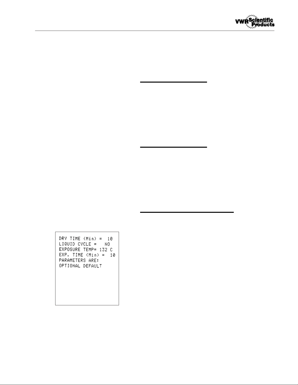
Press the "Optional Cycle" button and scroll
the setpoint temperature below 100°C. You
will enter a menu for an optional drying cycle.
Set the drying time as instructed above, then
press "Start Cycle" to begin the drying cycle.
O
PERATION
Warning
Use caution when
opening the sterilizer
door. Stand to the side
behind the door and
open door slowly and
partially to protect
yourself from escaping
steam or boiling liquids
and exploding flasks.
Do not attempt to open
sterilizer door until the
display reads "Cycle
Complete." Pressure
within the chamber could
cause the door to open
with extreme force,
possibly causing
personal injury.
Page 40
40
The printer is a thermal printer that provides a
paper tape record for future reference. The printed
paper tape is verification of sterilizer performance,
load control identification and quality assurance
checks for each cycle.
The printer operates with electronic impulses on
special paper. It requires no ribbons and therefore
no ribbon changing. The printer is located below
the keypad on the front of the sterilizer.
Printer Access
The printer is protected by a protective cover. The
printer cover pulls off the front when you squeeze
the pins on each side and pull forward. The printer
will then slide forward when you pull gently on the
metal tab provided on the leading edge of the printed circuit board.
The printed paper tape exits the printer through a
slot in the access door. The slot also allows for
easily tearing off the paper tape as needed.
Paper Advance Button
A paper advance button is located on the upper
right corner of the printer. Pressing the paper
advance button while the printer is inactive will
advance the paper through the printer. The paper
advance button is useful for installing a new roll of
paper tape and for advancing a tape for tearing off
at the end of a sterilization cycle.
Printer
Caution
Do not allow steam from the
open chamber door to contact the paper tape. The
steam's heat will blacken the
paper, making the tape
unreadable.
Note
A colored stripe along the
edge of the paper indicates
that you are approaching the
end of the tape. When the
stripe appears,
approximately 23 inches of
paper remain, enough for
2-3 cycles. Replace the tape
before it is completely
exhausted to ensure a
complete record of your
sterilization procedures.
Page 41
41
PRINTER
Paper Tape Rolls
The special heat sensitive paper for the printer is
available from VWR (Part Number PRX2). The
printer will not print on plain paper. Refer to the
Maintenance section of this manual for paper roll
installation.
Printer Operation
The printer automatically records sterilization
cycles. During sterilization cycles, the printer prints
the chamber temperature, pressure and status of
cycle at one minute intervals. The operator has the
option of choosing not to use the printer.
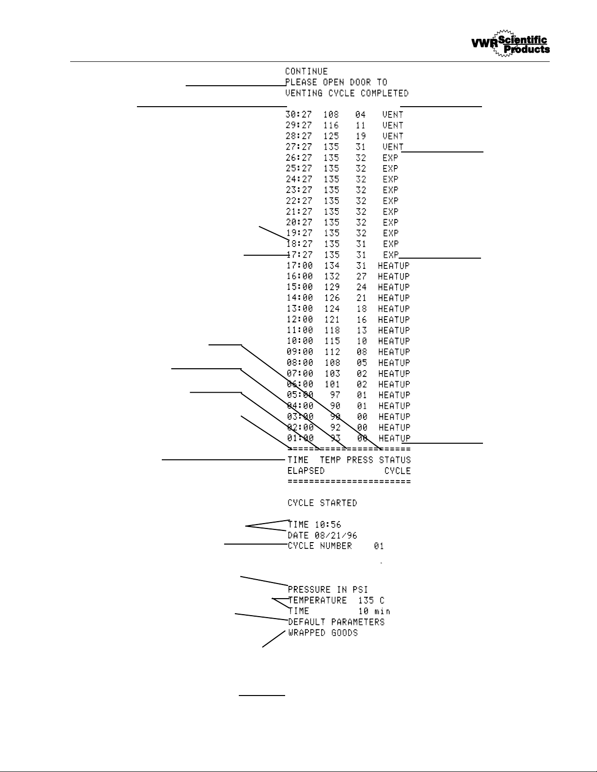
Printer Tape Description
The printer tape is designed to be easily read as a
cycle is running, allowing you to exam at a glance
the progress of the current cycle. As a result, a
complete tape must be read from the bottom up.
(Sample on page 41)
When you turn on the sterilizer, the printer will
print "VWR AccuSterile" and the software version
number. This will print only immediately after the
sterilizer has been turned on.
When you press one of the preset cycle buttons,
the printer will print the name of the cycle selected,
the parameters set for that cycle and the selected
pressure units. If you choose a default optional
cycle, the printer will print the current default parameters. If you bypass the default optional cycle for
a standard, the printer will print only the name of
the cycle and the selected pressure units, since the
parameters have not been set.
Page 42

42
PRINTER
When you press "Start Cycle", the printer will
print the number of cycles that have been run since
the unit was turned on, the current date and time,
the notation "Cycle Started" and column headers.
During the cycle, the printer will print the elapsed
time, the current chamber temperature and the
current chamber pressure at one minute intervals,
along with a status notation.
When the sterilizer chamber achieves the
temperature set by the cycle parameters, the
printer will immediately print a record line,
regardless of the time since the last record was
printed. The status notation will change from
"Heatup" to "Exp", indicating that the load is being
exposed to the temperature set forth in the cycle
parameters. The printer will continue to print record
lines at one minute increments, starting one minute
after the record line printed at the start of the
exposure phase but still showing the total elapsed
time for the cycle.
When the sterilizer has achieved the time
condition set in the cycle parameters, the printer
will print "Vent" in the cycle status column,
indicating that the sterilizer is venting.
At the end of the vent phase, the printer will print
"Venting Cycle Completed" and instructions for
starting the drying cycle. There is no printout during
the drying cycle.
Printer Record Storage
In addition to being heat-sensitive, the paper tape
is also light sensitive and will darken if left exposed
to light for an extended length of time. To ensure
the long-term legibility of your records, it is
important that you keep your printed tapes in a
dry, cool, dark place.
Page 43
43
Printer Mode is (USED)
Version 3.0
Accu Sterile
VWR
Software version number prints
when you turn on the sterilizer.
Name of preset program chosen for
this cycle
Parameters for this programmed
cycle (default for this preset
program)
Currently chosen pressure units
Date and time of cycle initiation
Cycle record number for day
Column Headers
Elapsed time since cycle started
Chamber Temperature
Chamber Pressure
Current status of the cycle
Exact point at which sterilization
phase begins.
Elapsed time increments by minutes
from start of sterilization phase
Instructions for drying
End of cycle
Vent
Phase
Exposure
Phase
Heatup
Phase
P
RINTER
Page 44

44
Special Operating Conditions
Warning
Do not attempt to open sterilizer door until the display
reads "Cycle Complete".
Pressure within the chamber
could cause the door to
open with extreme force,
possibly causing personal
injury.
Reprocess your load in the
event the sterilizing cycle
has been terminated prematurely. The load may not be
sterile when the sterilizing
cycle has been terminated
prematurely.
Failure to drain excess water
from the sterilizer chamber
after a cycle abort may result
in subsequent unsterile
loads as a result of contact
with water in the chamber.
Always drain excess water
from the chamber after
aborting a cycle.
Allow chamber to cool
before draining excess
water.
Note
If display shows: "The Mechanical
OTP has Tripped. Shutoff Unit
Power and Reset - Caution - Unit
Hot!!" Reset as described under
"Resetting the Mechanical OTP
Sensor" in Service Manual.
Emergency Off (Cycle Abort)
Pressing the "Stop" button will immediately terminate sterilization. Allow the sterilizer to cool and
press the "Stop" button again to reset the sterilizer.
Proceed with a new sterilization cycle normally.
When terminating a load, pressing the "Stop"
button will vent steam from the chamber back into
the reservoir.
Resetting the Automatic OTP
Display shows: "Cycle Aborted Due to AUTO OTP
Device. Press Stop Shutoff Unit Power to Reset."
1. Press the "Stop" button.
2. Wait for the display to read "Select Cycle".
3. Turn Power Switch off and then on to
reset the Low Water Cutoff.
4. Open the chamber door and allow the
chamber to cool.
5. Select your desired cycle and run the
cycle with a loaded chamber to verify
operation.
6. In the event of a repetition of fault call
VWR Customer Service.
Page 45
45
SPECIAL OPERATING SITUATIONS
Warning
Reprocess your load in
the event the sterilizing
cycle has been terminated
prematurely. The load
may not be sterile when
the sterilizing cycle has
been terminated prematurely.
Warning
Reprocess your load in
the event the sterilizing
cycle has been terminated prematurely. The load
may not be sterile when
the sterilizing cycle has
been terminated prematurely.
Erratic Controls Display or
Operation
Abnormal sterilizer operation or controls display
could be caused by an internal or external
electrical voltage surge. Such a voltage surge
could be cause be any of a number of events: a
momentary surge in the power supply, a nearby
lightening storm, or even a static electrical charge
carried by operating personnel.
Abnormal operation or displays are not common
occurrences and may never happen. No damage to
the equipment will occur if such an event should
happen.
If an abnormal condition should occur, terminate
any processing cycle in process. (Press "Stop.")
Reset the sterilizer by turning the power switch (on
the front right corner of the unit) to OFF. Wait 30
seconds and turn the power switch back on. Select
your desired cycle and proceed with normal
operation.
Power Failure During Sterilizing
Cycle
All Selector/Indicator Panel lights will be off.
Allow the unit to cool. Reset the sterilizer by turning
the power switch (under the front right corner of the
unit) to OFF. Wait 30 seconds and turn the power
switch back on. Drain excess water from the
sterilizer chamber. Then reprocess your load
normally.
Page 46

46
Problem Solving Chart
Fault Indication Fault Cause Solution
:sdaeryalpsid,detlahelcyC
putaeHoTeuDdetlaHelcyC"
putaeHmumixaMgnideecxE
".teseRoTpotShsuP,emiT
ehtnierutarepmetehT
dehcaertonsahlessev
tnioptesdeificepseht
,setunim57nihtiw
etauqedarofkcehC.1
fogninnigebehttallifretaw
.elcyc
/sevlavdioneloskcehC.2
.skaelrofteksagrood
tonlliwreziliretS"eeS.3
".taeh
:sdaeryalpsid,detlahelcyC
revOoTeuDdeliaFelcyC"
,noitidnoCerutarepmeT
".eunitnoCoT".potSsserP
5ϒ .tnioptesehtevobaC
1naht ϒ eromtontubC
denehtgnelesahperusopxE
.emitdemmargorpdnoyeb
,sdaeryalpsiddetlahelcyC
woLoTeuDdeliaFelcyC"
,noitidnoCerutarepmeT
".eunitnoCoTpotSsserP
:sdaeryalpsid,detlahelcyC
,denepOsaHrooDehT"
,detrobAelcyCnoitaziliretS
".eunitnoCoTpotSsserP
5naht ϒ ehtwolebC
).elcycdiuqil
1naht ϒ ehtwolebC
.elcyc
edisnierutarepmetehT
sahrebmahceht
nahteromdedeecxe
.elcyc
ehtnierutarepmeT
eromdeppordrebmahc
ehtgnisuac,tnioptes
otremitesahperusopxe
otelbacilppatoN(.teser
ehtnierutarepmeT
eromdeppordrebmahc
diuqilanitnioptes
5nahteromro,elcyc ϒC
.elcycrehtoynani
denepohctiwsroodehT
afonoitaitiniehtretfa
.elcyc
otrebmahcwolla
otrebmahcwolla
otrebmahcwolla
,nottubPOTSehtsserP
,loocdnaezirusserped
tratser,rebmahcehtniard
sidaoL.yrassecenenoN
.elcycfodnetaelirets
,nottubPOTSehtsserP
,loocdnaezirusserped
tratser,rebmahcehtniard
,nottubPOTSehtsserP
,loocdnaezirusserped
tratser,rebmahcehtniard
ehttahtgnirusne,elcyc
.desolcylerucessirood
yalpsid,tratstonseodelcyC
,nepOsIrooDehT"sdaer
".eunitnoCoTrooDesolC
saHtinU":sdaeryalpsiD
eroMenOroFretaWhguonE
llifeResaelP,elcyC
".riovreseR
.desserp
.retawwol
sawhctiwsroodehT
sawTRATSnehwnepo
.desolcsi
hctiwslevelretawehT
deneporiovreserni
gnitacidni,llifehtgnirud
a
.elcycrehton
elcyC.ylerucesroodesolC
hctiwsroodnehwtratslliw
retfA.nurotelcycwollA
llifer,dednesahelcyc
gninnurerofebriovreser
Page 47
47
PROBLEM SOLVING CHART
noitacidnItluaFseuaCtluaFonituloS
yalpsid,tratstonseodelcyC
.ytpmEsIriovreseR"sdaer
noitaziliretStratseRdnAlliF
".elcyC
eht,desserpsiPOTSnehW
erusserP"sdaeryalpsid
esaelP,ISP1nahTretaerG
".potSottiaW
tadesserpsiTRATSnehW
,esahpgniyrdehtfodneeht
tsuMrooD"sdaeryalpsideht
gniyrDnigeBoTnepOeB
.elcyC
erusserprevolacinahceM
gnitnev,snepoevlavfeiler
.rebmahcmorferusserp
elcyC",sdaeryalpsiD
citamotuAoTeuDdetrobA
.POTSsserP.eciveDPTO
oTrewoPtinUffotuhS
".tratseR
ehttaneposi
ehtnierusserP
.ISP54
hctiwslevelretawehT
,elcycafogninnigeb
.retawwolgnitacidni
,deppotssahelcycehT
rebmahcehttub
ottaergootsierusserp
.roodehtnepoylefas
rooD(.desolcsirooD
rofnepoebtsum
).gniyrdetauqeda
otrebmahcwolla
dedeecxesahrebmahc
.ecivreS
norosneserutarepmeT
dehcaersahretaeheht
,tniopffo-tucteserpsti
.eruliafrosnesro
.ecivreS
.elcyctratseR.riovreserllifeR
.pordoterusserproftiaW
.tratSsserP.roodnepO
,nottubPOTSehtsserP
.elcyctratseR.ezirusserped
fonoititeperafotneveehtnI
remotsuCRWVllac,tluaf
fonoititeperafotneveehtnI
remotsuCRWVllac,tluaf
.taehtonlliwreziliretS
ehT",sdaeryalpsiD
saHPTOlacinahceM
rewoPtinUffotuhS.deppirT
tinU-noituaC-teseRdnA
"!!toH
efas-liafehT
lacinahcem
hctiwserutarepmetrevo
oteuddeneposah
lamrehttnacifingis
.yawanur
C
.ecivreSremotsu
rednudebircsedsateseR
lacinahceMehtgnitteseR"
ecivreSni"rosneSPTO
afotneveehtnI.launaM
RWVllac,tluaffonoititeper
Page 48
48
Maintenance Schedule Chart
deriuqeRecnanetniaMelbisnopseRnosreP
yliaD
teksaGrooDnaelCresU
*rebmahCnaelCresU
ylkeeW
kcaRdnasyarT,rebmahCnaelCresU
ylhtnoM
evlaVfeileRerusserPkcehClennosrepecivresdeifilauQ
riovreseRnaelCresU
ylraeY
noitacifireVtuodaeRerutarepmeTlennosrepecivresdeifilauQ
deriuqeRsA
lloRrepaPllatsnIresU
teksaGrooDgnignahClennosrepecivresdeifilauQ
.sdaoldiuqilgnissecorpnehW*
Page 49
49
Maintenance
Warning
Refer servicing to qualified
personnel.
Never use a wire brush,
steel wool, abrasive material,
or chloride-containing products to clean door and
chamber assembly.
"Caution: Hot Surface. Avoid
Contact." Ensure that the
sterilizer is cool before
cleaning to avoid burns.
Caution
Failure to keep the interior of
the stainless steel chamber
free of mineral deposits and
debris can cause premature
failure of the sterilizer.
Warning
To prevent collection of mineral deposits and corrosion
of chamber components, use
distilled or deionized water
only as specified. Clean
chamber after each use if
sterilizing saline solutions.
Daily Maintenance
Cleaning Door Gasket
The door gasket and the mating surface should be
wiped clean each day with a clean, damp cloth. Do
not use abrasive cleaners on the gasket or mating
surface.
The gasket should be examined for cracks and
damage that could result in a poor pressure seal. If
replacement is necessary, refer to Gasket
Replacement under the When Required heading of
this Maintenance section.
Cleaning After Liquid Loads
Biological media tends to boil at a higher rate than
other liquids during venting. This causes media to
be spattered inside the chamber. Therefore, the
chamber must be cleaned daily when you are
sterilizing media. Clean as follows:
1. Allow unit to cool.
2. Wipe out chamber and door with a clean,
damp cloth.
Weekly Maintenance
(More often if necessary.)
Cleaning Chamber, Trays and Rack
At least once a week, the trays and tray rack
should be removed from the sterilizer chamber.
The trays, tray rack and chamber should be thoroughly cleaned to remove any deposits from the
Page 50

50
MAINTENANCE
Warning
Pressurized steam will be
discharged when the relief
valve is opened. To prevent
burns, place a steam barrier
(such as a rolled towel)
around the opening in the
back of the unit. To prevent
burns, wear gloves or use an
extension device if it
becomes necessary to
operate the pull ring.
surfaces.
Clean the trays, rack and chamber (especially
the bottom of the chamber) with appropriate
anti-biological cleaners. Wipe all residue from the
surfaces with a dampened, lint-free cloth.
Monthly Maintenance
Pressure Relief Valve Check
To ensure that the pressure relief valve is
functioning properly, you must have a qualified
person check the valve each month.
round access hole in the back panel. A suitable
tool (screwdriver, rod, etc.) will be needed to test
the pressure valve.
1. Run a sterilize cycle at 135°C (275°F)
without a load in the chamber.
2. Allow the pressure in the chamber to
reach 30 psi (206 kPa).
3. Insert a suitable tool through the access
hole and push the lever on the pressure
relief valve. Push the valve lever away
from the valve to open the valve. Hold the
valve open for 3 seconds. Steam should
discharge freely.
4. Release the valve lever. The steam
discharge should cease entirely.
5. After checking the valve, turn the sterilizer
off by pressing "Stop" to prevent
overheating.
If the valve malfunctions, the valve must be
replaced.
Page 51

51
MAINTENANCE
Note
In the event that you have
lost the supplied drain
tubing, you can drain the
reservoir as follows:
1. Tilt the front of the sterilizer
up until you can access the
small panel on the bottom
front of the sterilizer,
beneath the drain assembly.
2. Remove the screws securing
the panel. Remove the
panel.
3. Have a suitable container
prepared for the water in the
reservoir. Disconnect the
reservoir drain tube from the
quick disconnect fixture on
the front of the sterilizer. The
reservoir will drain.
Note
Do not add more than 7 liters
of water to the reservoir after
cleaning.
Cleaning Reservoir
1. The reservoir drain assembly is located on
the lower right front side of the sterilizer
cabinet. Place a suitable container below
the drain assembly. Connect the drain
adapter and tube to the drain assembly
and drain the reservoir into the container.
2. When the reservoir is empty, wipe out the
inside of the reservoir with a clean,
lint-free cloth. Take care not to push debris
back into the water line.
3. Refill the reservoir with distilled or low
quality water and replace the reservoir
cover.
Page 52
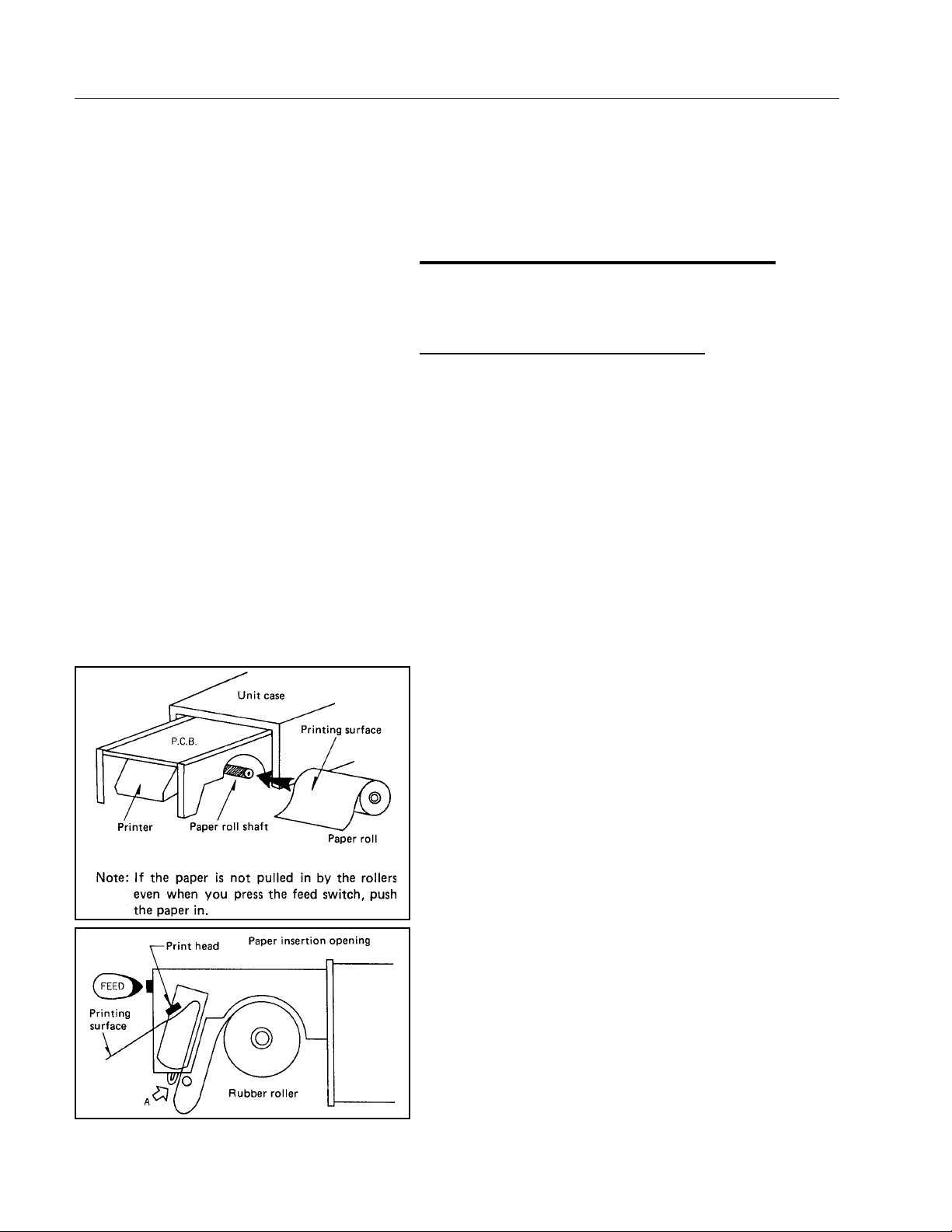
52
MAINTENANCE
Maintenance To Be Done As
Required
Paper Tape Roll Installation
The heat sensitive paper will print on only one side,
and therefore must be installed properly to function.
1. Remove the printer cover and pull out the
printer as described in Printer Access on
page 39.
2. Cut the lead end of the paper as shown in
the illustration. Install the paper roll on the
paper roll shaft. Note that the paper feeds
from the top forward.
3. Feed the cut end of the paper into the slot
at the bottom of the printer. Push the paper
into the printer until it stops. Press the
"Paper Feed" button on the printer until the
tip of the paper comes out the top of the
printer.
4. Pull enough paper through to be inserted
through the slot in the cover. Push the
printer back in.
5. Feed the paper through the cover and
replace the cover.
At the end of each day, the printed portion
of the printer tape should be removed and
stored properly. See "Printer Record
Storage" for details.
Page 53

53
MAINTENANCE
Changing Door Gasket
1. Disconnect the sterilizer from the power
supply. Ensure that the sterilizer is cool
and depressurized.
2. Remove the old gasket by pulling it out of
the door.
3. Use a warm, soapy water combination to
lubricate the gasket for easier installation.
4. Working around the door from one point,
insert the outer edge of the gasket under
the machined lip of the gasket groove in
the door.
5. Working around the door from one point,
press the inner edge of the gasket into the
gasket groove, ensuring that the gasket is
fully seated in the groove.
6. Reconnect the sterilizer to the power
supply.
Page 54
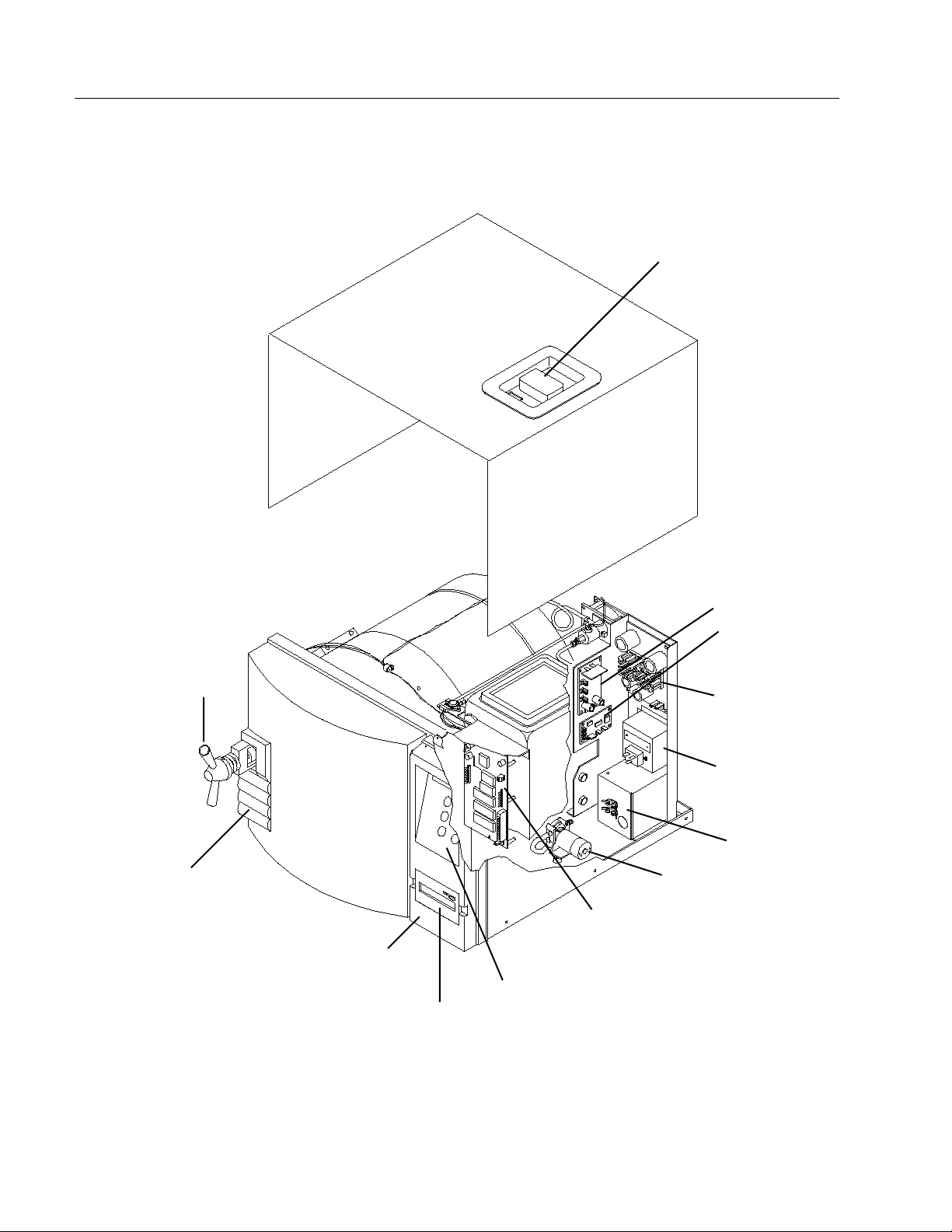
54
Figures
Reservoir Cover
Solenoid PC
Board
OTP PC Board
Power Supply
Board
Power Module
Transformer Fuses
Pump
Main Control Board
Membrane Panel
Printer Cover
On/Off Switch
Door Release
Door Handle
Sterilizer Component Layout - Interior
Page 55
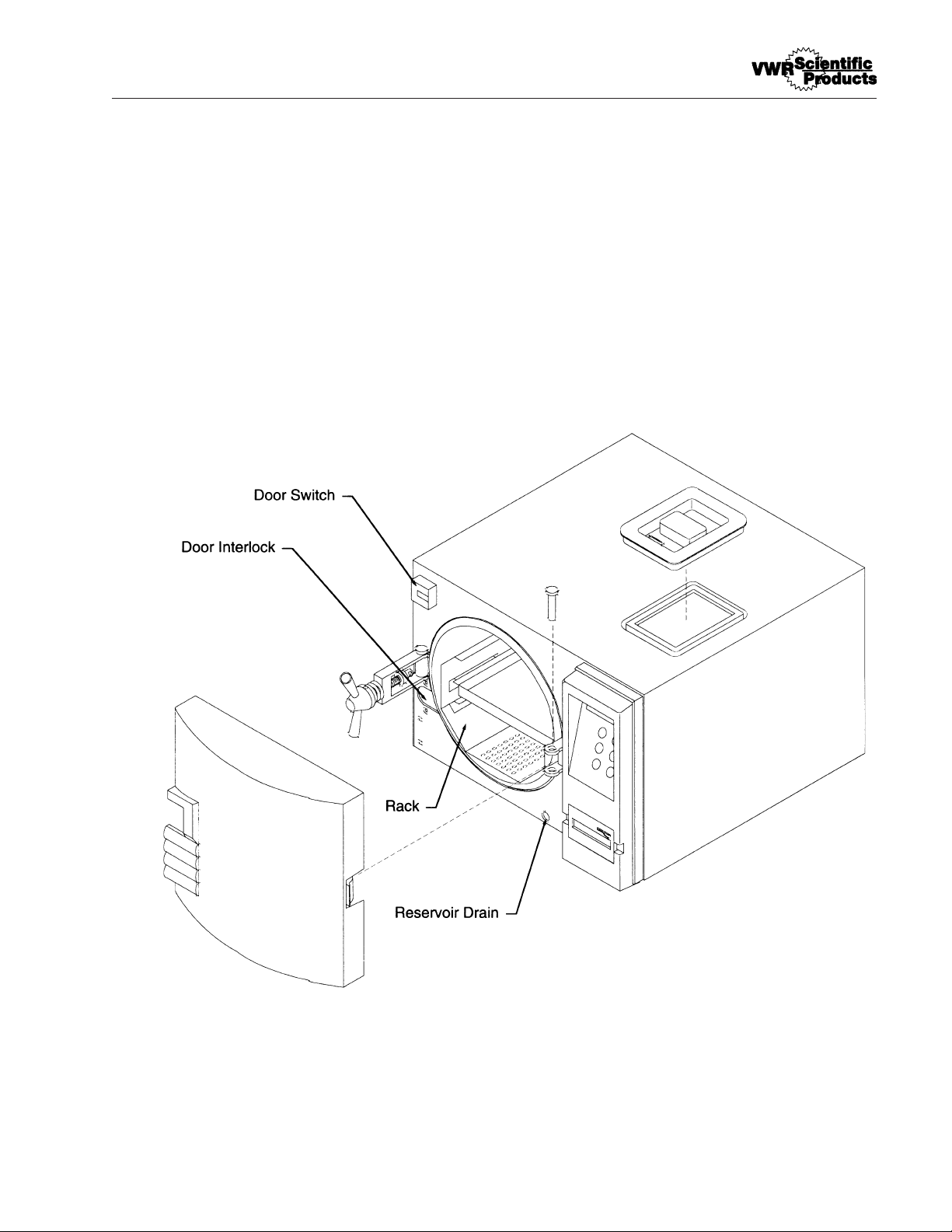
55
FIGURES
Sterilzer Component Layout - Chamber and Door
Page 56
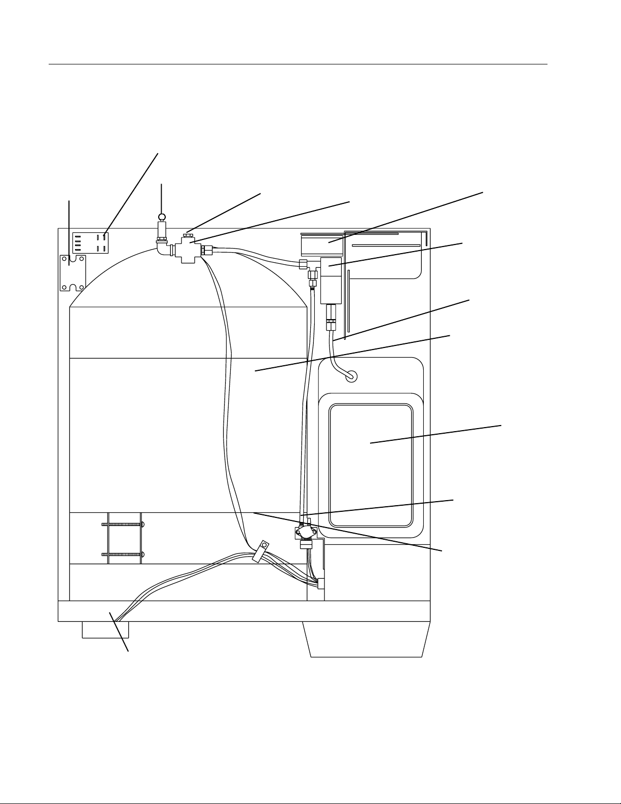
56
FIGURES
Solid State
Relay
OTP Mechanical Relay
Pressure Relief Vave
Calibration Port
Temperature Sensor
Fan
Vent Solenoid
Vent Line
Insulation
Reservoir
Pressure Transducer
Insulation Support
Bracket
Door Switch
Sterilizer Component Layout - Top View
Page 57

57
Parts List
120 V 220V~
Qty. Description Part No. Part No.
1 Printer Paper Tape Roll PRX2 PRX2
2 Solenoid Valve RY759X1A RY759X1A
1 PC Board (Power Supply) PC759X4A PC759X4A
Transformer TN759X1A TN759X2A
PC Board (Solenoid) PC1118X5 PC1118X5
Pressure Relief Valve PMX117 PMX117
Tank, Lower Float SW759X1A SW759X1A
PC Board (Logic) w/ printer PC1130X1 PC1130X1
PC Board (Logic) w/o printer PC1130X2 PC1130X2
ON/OFF Switch SWX141 SWX104
Terminal Strip TRX177 TRX177
Relay Contact RYX60 RYX60
Pump PUX16 PUX16
Printer Cover CV759X5 CV759X5
Printer AYX3 AYX3
Door Gasket GS759X1A GS759X1A
Fan FA759X2A FA759X1A
Heater ELX9 ELX10
Gasket (Chamber) GS759X4 GS759X4
Relay, Solid State RYX34 RYX34
PC Board (OTP) PC1118X2 PC1118X2
Tray (Large) TY759X2A TY759X2A
Tray (Small) TY759X3A TY759X3A
Door Switch SW1118X1 SW1118X1
Membrane Panel SWX175 SWX175
Water Reservoir TY759X1 ` TY759X1
Safety Latch SF759X1A SF759X1A
Shaft Ass'y (Main Door Latch) SF759X2A SF759X2A
Pressure Pin (Door) SP759X1 SP759X1
2 Handle (Yoke Assembly) HNX18 HNX18
1Drain Tube Assembly TU759X9A TU759X9A
Reservoir Cover DL759X2 DL759X2
Chamber Temp. Sensor RS759X1A RS759X1A
Automatic OTP Sensor RS759X2A RS759X2A
Mechanical OTP Sensor FZ759X1 FZ759X1
Line Filter CAX104
2 Fuse (Type Slow Blow,
250V, 1.6 amp) FZX47 FZX47
1 Pressure Transducer TDX5 TDX5
Warning
Replace fuses with same type and rating
Page 58

58
Ordering Procedures
Please refer to the Specification Plate for the complete model number, serial number, and
series number when requesting service, replacement parts or in any correspondence
concerning this unit.
All parts listed herein may be ordered from the VWR supplier from whom you purchased
this unit or can be obtained promptly from the factory. When service or replacement parts
are needed we ask that you check first with your dealer. If the dealer cannot handle your
request, then contact our Customer Service Department at 563-556-2241 or 800-553-0039.
Prior to returning any materials to VWR, please contact our Customer Service Department
for a “Return Goods Authorization” number (RGA). Material Returned without an RGA
number will be returned.
Page 59

59
Decontamination Statement
We cannot accept any product or component sent to VWR for repair or credit that is
contaminated with or has been exposed to potentially infectious agents or radioactive
materials.
No product or component will be accepted without a "Return Goods Authorization" (RGA)
number.
Page 60

Two Year Limited Warranty
VWR Scientific Products ("VWR") agrees to correct for the original user of this product, either by repair, or
at VWR's election, by replacement, any defects in material or workmanship which develop within twenty-four
(24) months after delivery of this product to the original user. In the event of replacement, the replacement will
be warranted for the remainder of the original twenty-four (24) month period or ninety (90) days, whichever is
longer.
If this product should require service, contact the VWR office nearest your location for instruction (for a
complete list of offices, see your VWR catalog). When the return of the product is necessary, a return
authorization number should be placed on the outside of the package and a detailed explanation of the defect
enclosed with the item.
This warranty shall not apply if the defect or malfunction was caused by accident, neglect, unreasonable use,
improper service, or other causes not arising out of defects in material or workmanship.
THERE ARE NO WARRANTIES, EXPRESSED OR IMPLIED, INCLUDING, BUT NOT LIMITED TO, THOSE
OF MERCHANTABILITY OF FITNESS FOR A PARTICULAR PURPOSE, WHICH EXTEND BEYOND THE
DESCRIPTION AND PERIOD SET FORTH HEREIN. VWR'S SOLE OBLIGATION UNDER THIS WARRANTY IS LIMITED TO THE REPAIR OR REPLACEMENT OF A DEFECTIVE PRODUCT AND VWR SHALL
NOT, IN ANY EVENT, BE LIABLE FOR ANY INCIDENTAL OR CONSEQUENTIAL DAMAGES OF ANY
KIND RESULTING FROM USE OR POSSESSION OF THE PRODUCT.
Some states do not allow (1) limitations on how long an implied warranty lasts or (2) the exclusion or limitation
of incidental or consequential damages, so the above limitations or exclusion may not apply to you.
This warranty gives you specific legal rights, and you may also have other rights which vary from state to
state.
 Loading...