

Page 1

-~
~I
Your
for
ARTISAN
TECHNOLOGY
definitive
quality
equipment.
GROUP
source
pre-owned
®
•
Critical
• In
with
We
along
Custom
so
your
stock/
Full-service,
experienced
buy
your
with
credit
engineering
equipment
and
expedited
Ready-to-ship
independent
engineers
excess,
for
buybacks
works
exactly as
services
repair
and
technicians
underutilized,
and
trade-ins
you
specify.
•
Leasing
•
!TAR-certified
center
and
.
/
Rentals/
on staff.
idle
Demos
secure
equipment
asset
solutions
Artisan Technology
Group
Expert
All
tr
ademarks,
team
br
a
nd
names, a
I
Trust
nd
br
guarantee
a
nd
s a
pp
earing he re
Find the VWR 1575 at our website: Click HERE
in
are
th
I
100%
e pr operty of
satisfaction
th
e
ir
r
es
pecti
ve
ow
ner
s.
Page 2

INCUBATORS
MODELS: 1575, 1575R
ORBITAL SHAKING INCUBATOR
INSTALLATION AND OPERATION MANUAL
Artisan Technology Group - Quality Instrumentation ... Guaranteed | (888) 88-SOURCE | www.artisantg.com
Page 3

These units are general purpose incubators for professional, industrial or educational use where the
preparation or testing of materials is done at approximately atmospheric pressure and no flammable,
volatile or combustible materials are being heated. These units are not intended for hazardous or
household locations or use.
Sheldon Manufacturing Inc.
P.O. Box 627
Cornelius, Oregon 97113
EMAIL: [email protected]
INTERNET: http://www.Shellab.com
PHONE: 1-800-322-4897, (503) 640-3000
FAX: (503) 640-1366
2 Orbital Shaking Incubator
Artisan Technology Group - Quality Instrumentation ... Guaranteed | (888) 88-SOURCE | www.artisantg.com
Page 4

TABLE OF CONTENTS
INTRODUCTION........................................................................................................................................... 6
General Safety Considerations ........................................................................................................6
RECEIVING YOUR UNIT.............................................................................................................................. 7
Inspection Guidelines....................................................................................................................... 7
Accessories...................................................................................................................................... 7
Returning Shipment ......................................................................................................................... 7
Recording Data Plate Information.................................................................................................... 8
GRAPHIC SYMBOLS ...................................................................................................................................9
CONTROL PANEL OVERVIEW ................................................................................................................. 10
Power Switch ................................................................................................................................. 10
Main Temperature Control .............................................................................................................10
Heating Lamp................................................................................................................................. 10
Overtemperature Thermostat......................................................................................................... 10
Safety Lamp ...................................................................................................................................11
Shaker Switch ................................................................................................................................ 11
Oscillation Controller ...................................................................................................................... 11
Auxiliary Control Panel................................................................................................................... 11
Light…. ……. .................................................................................................................................. 12
ACCY….......................................................................................................................................... 12
INSTALLATION........................................................................................................................................... 13
Location.......................................................................................................................................... 13
Lifting and Handling .......................................................................................................................13
Leveling.......................................................................................................................................... 14
Power Source................................................................................................................................. 14
Cleaning .........................................................................................................................................14
OPERATION ...............................................................................................................................................15
Turning On the Unit........................................................................................................................ 15
Installing the Sample Tray ............................................................................................................. 15
Setting the Main Temperature Control........................................................................................... 15
Calibrating the Main Temperature Control..................................................................................... 16
Setting the Overtemperature Thermostat ...................................................................................... 16
Setting the Oscillation Control........................................................................................................ 16
Setting the Oscillation Stroke......................................................................................................... 17
Setting the Counterbalance ........................................................................................................... 17
Interior Accessory Outlet................................................................................................................ 21
MAINTENANCE .......................................................................................................................................... 22
Cleaning .........................................................................................................................................22
Disinfecting..................................................................................................................................... 22
Controls.......................................................................................................................................... 22
TROUBLESHOOTING ................................................................................................................................ 23
PARTS LIST................................................................................................................................................ 29
Orbital Shaking Incubator 3
Artisan Technology Group - Quality Instrumentation ... Guaranteed | (888) 88-SOURCE | www.artisantg.com
Page 5

UNIT SPECIFICATIONS............................................................................................................................. 31
SCHEMATICS............................................................................................................................................. 33
FIGURES
Figure 1. Control Panel ...............................................................................................................................10
Figure 2. Auxiliary Control Panel ................................................................................................................11
Figure 3. Setup for ½ Inch Stroke ...............................................................................................................18
Figure 4. Setup for ¾ Inch Stroke ...............................................................................................................19
Figure 5. Setup for 1 Inch Stroke ................................................................................................................20
Figure 6. Wire Diagram ............................................................................................................................... 33
TABLES
Table 1. Data Plate Information .................................................................................................................... 8
Table 2. Symbols ..........................................................................................................................................9
Table 3. Counterbalance Starting Locations...............................................................................................17
Table 4. Temperature Troubleshooting....................................................................................................... 23
Table 5. Refrigeration Troubleshooting (R Suffix Models Only) .................................................................26
Table 6. Mechanical Troubleshooting ......................................................................................................... 27
Table 7. Miscellaneous Troubleshooting ....................................................................................................28
Table 8. Parts.............................................................................................................................................. 29
Table 9. Temperature.................................................................................................................................. 31
Table 10. Capacity ......................................................................................................................................31
Table 11. Dimensions .................................................................................................................................31
Table 12. Shaking Mechanism.................................................................................................................... 32
Table 13. Refrigeration................................................................................................................................ 32
Table 14. Electrical...................................................................................................................................... 32
4 Orbital Shaking Incubator
Artisan Technology Group - Quality Instrumentation ... Guaranteed | (888) 88-SOURCE | www.artisantg.com
Page 6

REVISION HISTORY
Manual Revision Updates
4861237V 10-02 Initial release
4861237V 10-04 Additional information and additions.
4861237V 11-05 Additional information and additions.
4861237V 04-07 Spec Sheet Revsion
4861237V 01-08 Updated Wiring Diagram
4861237V 06-08 Updated Parts List Condensing Units
Orbital Shaking Incubator 5
Artisan Technology Group - Quality Instrumentation ... Guaranteed | (888) 88-SOURCE | www.artisantg.com
Page 7

Section
1
INTRODUCTION
Thank you for choosing an orbital shaking incubator. These units are not intended for use at hazardous or
household locations.
Before you use the unit, read this entire manual carefully to understand how to install, operate, and
maintain the unit in a safe manner. Your satisfaction with the unit will be maximized as you read about its
safety and operational features.
Keep this manual on-hand so it can be used by all operators of the unit. Be sure all operators of the unit
are given appropriate training before you put the unit in service.
Note: Use the unit only in the way described in this manual. Failure to follow the guidelines and
instructions in this manual may be dangerous and illegal.
General Safety Considerations
Your incubator and its recommended accessories have been designed and tested to meet strict safety
requirements.
For continued safe operation of your incubator, always follow basic safety precautions including:
• Read this entire manual before using the incubator.
• Be sure you follow any city, county, or other ordinances in your area regarding the use of this unit.
• Use only approved accessories. Do not modify system components. Any alterations or modifications
to your incubator may be dangerous and will void your warranty.
• Always plug the unit’s power cord into a grounded electrical outlet that conforms to national and local
electrical codes. If the unit is not grounded, parts such as knobs and controls may conduct electricity
and cause serious injury.
• Do not connect the unit to a power source of any other voltage or frequency beyond the range stated
on the data plate at the rear of the unit.
• Do not modify the power cord provided with the unit. If the plug does not fit an outlet, have a proper
outlet installed by a qualified electrician.
• Avoid damaging the power cord. Do not bend it excessively, step on it, place heavy objects on it. A
damaged cord can easily become a shock or fire hazard. Never use a power cord after it has become
damaged.
6 Orbital Shaking Incubator
Artisan Technology Group - Quality Instrumentation ... Guaranteed | (888) 88-SOURCE | www.artisantg.com
Page 8

Section
RECEIVING YOUR UNIT
Before leaving our factory, all units are packaged in high quality shipping materials designed to provide
protection from transportation related damage.
Once a unit leaves our factory, however, safe delivery becomes the responsibility of the carrier who is
liable for loss or damage to your unit. Damage sustained during transit is not covered under your unit
warranty.
When you receive your unit, inspect it for concealed loss or damage to its interior and exterior. Should
you find any damage to the unit, follow the carrier’s procedure for claiming damage or loss.
Inspection Guidelines
Carefully inspect the shipping carton for damage. If the carton is damaged, report the damage to the
carrier service that delivered the unit.
If the carton is not damaged, open the carton and remove its contents. Verify that all of the following
equipment is included in the crate:
• Two (2) shelves
• Eight (8) shelf clips
• One (1) sample tray
• Six (6) counter weights
• Four (4) leveling feet
Accessories
Carefully check all packaging before discarding. Save the shipping carton until you are sure everything is
in order.
Returning Shipment
If you must return the unit for any reason, first contact your service representative for authorization. You
will be asked to provide the data plate information. See Recording Data Plate Information below.
Orbital Shaking Incubator 7
Artisan Technology Group - Quality Instrumentation ... Guaranteed | (888) 88-SOURCE | www.artisantg.com
Page 9

2
Recording Data Plate Information
Once you have determined the unit is free from damage, locate the data plate at the back of the unit. The
data plate indicates your unit’s model number and serial number. Record this information below for future
reference.
Table 1. Data Plate Information
Model Number
Serial Number
Part Number
Voltage
8 Orbital Shaking Incubator
Artisan Technology Group - Quality Instrumentation ... Guaranteed | (888) 88-SOURCE | www.artisantg.com
Page 10
Section
GRAPHIC SYMBOLS
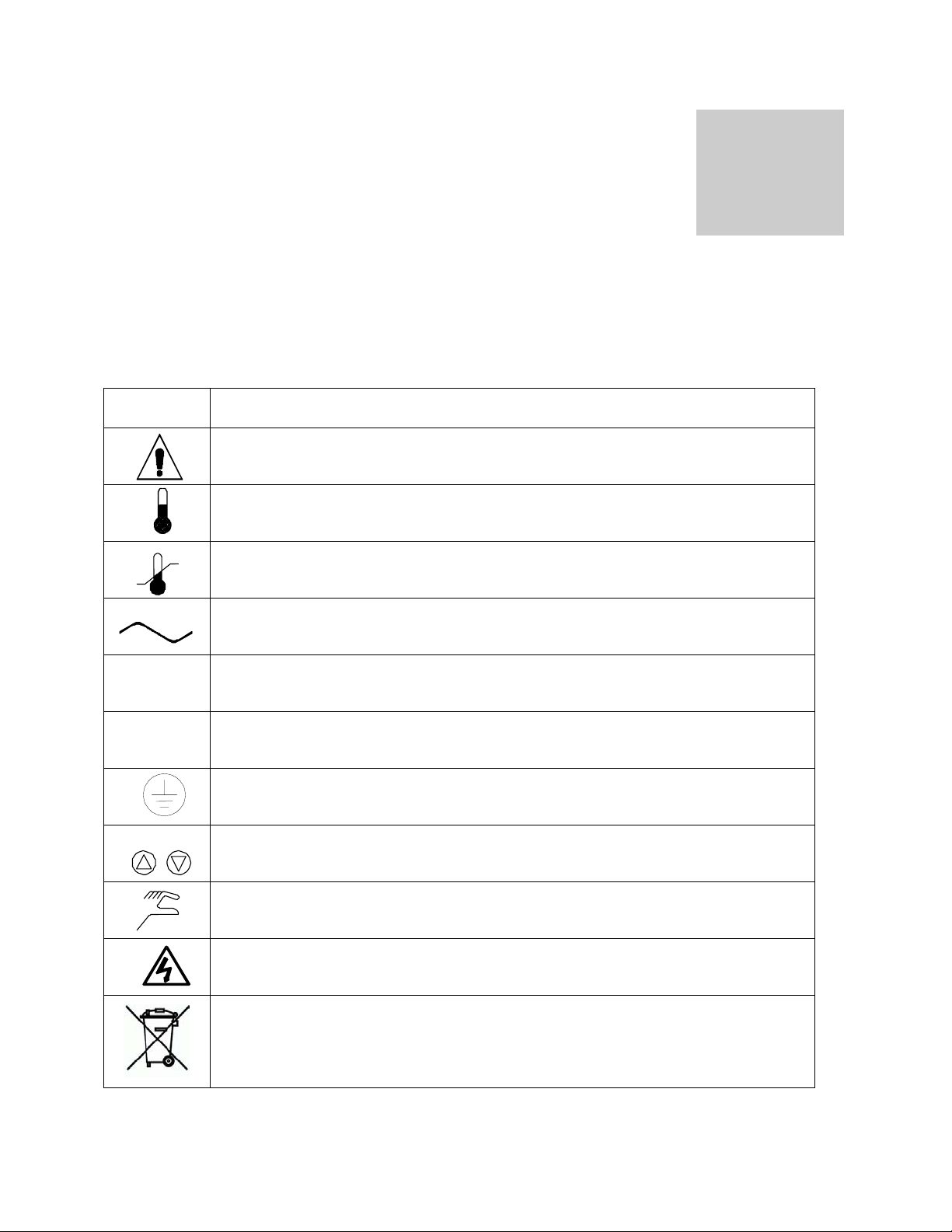
Your unit is provided with a display of graphic symbols that will help in identifying user adjustable
components.
Table 2. Symbols
Symbol
I
O
Identification
Indicates that you should consult your operator’s manual for further instructions.
Indicates “Temperature”
Indicates “Overtemperature Protection”
Indicates “AC Power”
Indicates the power is “ON”
Indicates the power is “OFF”
Indicates “Protective Earthground”
Indicates “Up” and “Down” respectively
Orbital Shaking Incubator 9
Indicates “Manually Adjustable”
Indicates “Potential Shock Hazard” behind partition
Indicates “Unit should be recycled” (Not disposed of in land-fill)
Artisan Technology Group - Quality Instrumentation ... Guaranteed | (888) 88-SOURCE | www.artisantg.com
Page 11
CONTROL PANEL OVERVIEW
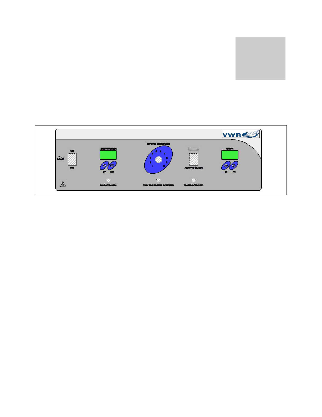
Figure 1 provides an illustration of the control panel.
Figure 1. Control Panel
Section
Power Switch
The main power I/O (on/off) switch controls all power to the unit and must be in the I position before any
systems are operational.
Main Temperature Control
Marked °C, the Main Temperature Control consists of the digital display and Up/Down arrow pads for
inputting set point temperature and calibration.
Heating Lamp
This pilot lamp is ON when the unit is heating up to set point. It is blinking when the controlling
temperature is at set point.
Overtemperature Thermostat
This control is marked SET OVERTEMPERATURE. It is equipped with a graduated dial marked from 0 to
10 and a knob that requires a flat-edged tool for adjusting settings to eliminate accidental changes.
Completely independent of the Main Temperature Controller, the Overtemperature Thermostat guards
against any Main Temperature Controller failure, which would allow the temperature to rise past the set
point. If the temperature rises to the Overtemperature set point, this thermostat takes control of the
heating element and allows continued use of the incubator until the problem can be resolved, or service
can be arranged.
10 Orbital Shaking Incubator
Artisan Technology Group - Quality Instrumentation ... Guaranteed | (888) 88-SOURCE | www.artisantg.com
Page 12
4
We do not recommend operating the unit for an extended period of time using only the Overtemperature
as the temperature uniformity will be affected.
Safety Lamp
Located directly below the Overtemperature Thermostat, this pilot lamp comes ON when the
Overtemperature Thermostat is activated. During normal operating conditions, this light should never
come on.
Shaker Switch
Located to the right of the Overtemperature Thermostat, this switch engages the oscillation mode of the
incubator. To enable oscillation, this switch must be in the I position. This switch does not have to be ON
to adjust the oscillation set point.
Oscillation Controller
This control is labeled RPM and consists of the UP/DOWN arrow pads and a digital display that shows
oscillations per minute. This control is adjustable from 20 to 400 RPM.
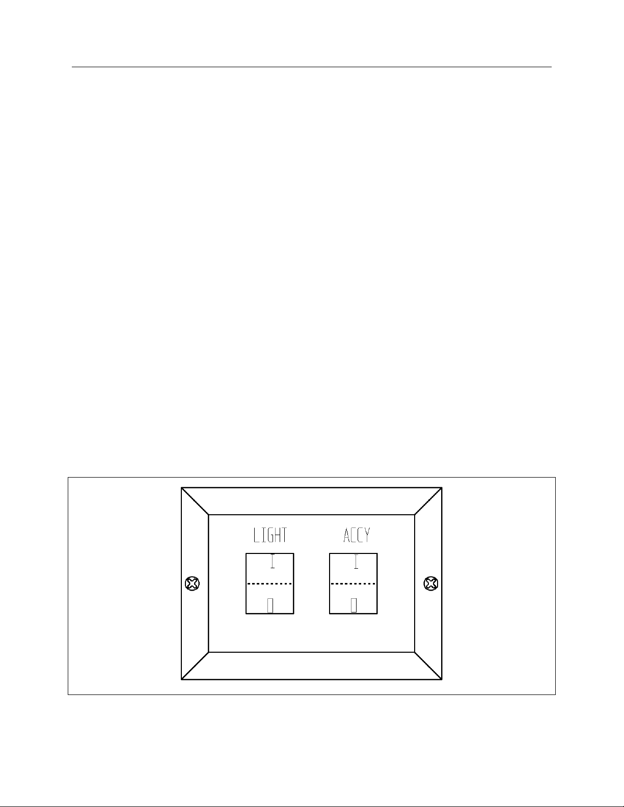
Auxiliary Control Panel
The Auxiliary Control Panel is located on the lower right hand side of the unit. See Figure 2.
Figure 2. Auxiliary Control Panel
Orbital Shaking Incubator 11
Artisan Technology Group - Quality Instrumentation ... Guaranteed | (888) 88-SOURCE | www.artisantg.com
Page 13

4
Light
The light switch controls the internal florescent inspection light.
ACCY
The ACCY switch controls the internal accessory outlet. See OPERATION for proper wiring and use of
this outlet.
12 Orbital Shaking Incubator
Artisan Technology Group - Quality Instrumentation ... Guaranteed | (888) 88-SOURCE | www.artisantg.com
Page 14

Section
INSTALLATION
This equipment must be used only for its intended application; any alterations or modifications will void
your warranty. Local city, county, or other ordinances may govern the use of this equipment. If you have
any questions about local requirements, please contact the appropriate local agency. The end user may
perform installation.
Under normal circumstances this unit is intended for use indoors, at room temperatures between 5° and
40°C, at no greater than 80% Relative Humidity (at 25°C) and with a supply voltage that does not vary by
more than 10%. Customer service should be contacted for operating conditions outside of these limits.
Location
In selecting a location, consider all conditions that might affect performance, for example:
• Heating/cooling ducts
• Ovens
• Stoves
• Autoclaves
• Direct sun
• Fast moving air currents
• High-traffic areas
Allow a minimum of 20 cm between the unit and walls or partitions that might obstruct free airflow.
Lifting and Handling
These units are heavy and care should be taken to use appropriate lifting devices that are sufficiently
rated for these loads. Follow the guidelines below when lifting and handling the unit.
• Units should be lifted only from their bottom surfaces.
• Doors, handles, and knobs are not adequate for lifting or stabilization.
• The unit should be completely restrained from tipping while lifting or transporting.
• All moving parts, such as shelves and trays, should be removed and doors must be positively locked
in the closed position during transfer to prevent shifting and damage.
13 Orbital Shaking Incubator
Artisan Technology Group - Quality Instrumentation ... Guaranteed | (888) 88-SOURCE | www.artisantg.com
Page 15

5
Leveling
The unit must sit levelly and solidly. Leveling feet are supplied and must be installed in the four holes in
the bottom corners of the unit. Turn the leveling feet counterclockwise to raise the level. Adjust the foot
at each corner until the unit stands levelly and solidly without rocking.
Note: If the unit must be moved, turn the leveling feet all the way clockwise to prevent damage while
moving.
Power Source
Check the data plate for voltage and ampere requirements before making a connection. VOLTAGE
SHOULD NOT VARY MORE THAN 10% FROM THE DATA PLATE RATING. This unit is intended for
50/60 Hz application. We recommend a separate circuit to prevent loss of product due to overloading or
circuit failure.
Note: Electrical supply to the unit must conform to all national and local electrical codes.
Cleaning
The incubator interior was cleaned at the factory but not sterilized. See MAINTENANCE for cleaning and
sterilizing instructions.
14 Orbital Shaking Incubator
Artisan Technology Group - Quality Instrumentation ... Guaranteed | (888) 88-SOURCE | www.artisantg.com
Page 16

Section
OPERATION
Turning On the Unit
To turn on the unit, perform the following steps:
1. Check the power supply against unit data plate; they must match.
2. Plug the service cord into the grounded electrical outlet. Ensure that the fuse is installed in the power
inlet of the unit.
3. Push the power switch to the ON position.
4. Turn the Overtemperature Thermostat to its maximum position, clockwise.
Installing the Sample Tray
To install the sample tray, perform the following steps:
1. Position the front two corners of the sample tray on the shaking mechanism.
2. Set the rest of the tray down
3. All corners of the shaking mechanism should be enclosed within the lips of the sample tray.
4. Shake the tray by its handles to confirm that it is firmly in place.
Setting the Main Temperature Control
To set the main temperature controller, perform the following steps:
1. Enter desired set point temperature. To enter set point mode on the controller, press either the UP or
DOWN arrow pad one time.
2. The digital display will start to blink, going from bright to dim. While blinking, the digital display is
showing the set point.
3. To change the set point, use the UP and DOWN arrow pads. If the arrow pads are not pressed for
five (5) seconds, the display will stop blinking and will read the temperature of the unit.
Note: The Overtemperature Thermostat at should be turned to its maximum position until the unit has
stabilized at desired set point temperature.
Allow the incubator at least 24 hours to stabilize.
15 Orbital Shaking Incubator
Artisan Technology Group - Quality Instrumentation ... Guaranteed | (888) 88-SOURCE | www.artisantg.com
Page 17

6
Calibrating the Main Temperature Control
We recommend that you calibrate your unit once it has been installed in its working environment and has
been stable at the set point for 24 hours. To calibrate the unit, perform the following steps:
1. Place a certified reference thermometer in the chamber by placing it either directly inside or through
the access tube at the top left of the unit. Ensure that the thermometer is not touching any shelving. If
you place the thermometer directly inside the chamber, taping the thermometer to a Petri dish will
raise it off the shelf and keep the scale in view.
2. Allow the temperature to stabilize again until the thermometer reads a constant value for one hour.
3. Compare the digital display with the reference thermometer.
4. If there is an unacceptable difference, put the display into calibration mode by pressing both the Up
and Down arrow pads at the same time for approximately five (5) seconds until the display blinks off
and on.
5. While blinking, the display can be calibrated by pressing the Up or Down arrow pads until the display
reads the correct value.
6. Allow the incubator temperature to stabilize again, and recalibrate if necessary.
Setting the Overtemperature Thermostat
To set the Overtemperature Thermostat, perform the following steps.
1. Once the incubator is stable at the desired set point, turn the Overtemperature Thermostat
counterclockwise until the Overtemperature indicator light turns on.
2. Turn the Overtemperature Thermostat clockwise just the safety indicator light turns off.
3. Continue to turn the Overtemperature Thermostat clockwise an additional two small divisions on its
scale past the point where the indicator light went out. This will set the Safety Thermostat at
approximately 1°C above the Main Temperature set point.
Setting the Oscillation Control
To set the oscillation control, perform the following steps:
1. Enter set point mode by pushing and releasing either the UP or DOWN arrow pad one time. The
display will start to blink on and off showing the RPM set point.
2. Push the UP or DOWN arrow pad to increase or decrease the RPM set point in increments of 10
RPM. The range for this set point is 30 – 400 RPM.
3. If the arrow pads are not pressed for five (5) seconds the display will stop blinking and revert to
displaying the actual RPM.
Note: For oscillation controls to work as described, the door must be completely closed.
16 Orbital Shaking Incubator
Artisan Technology Group - Quality Instrumentation ... Guaranteed | (888) 88-SOURCE | www.artisantg.com
Page 18

6
Setting the Oscillation Stroke
To set the oscillation stroke, perform the following steps.
Note: A 3/16 -inch Allen wrench should be used.
1. Assure that the power cord has been disconnected to prevent accidental operation.
2. Remove sample tray.
3. Open the access panel by rotating the wing nut ¼ turn counterclockwise and rotate the counterweight
platform until the stoke adjuster appears.
4. Remove the locking bolt and adjust the arm to any of the available options.
5. The dimensions shown are the total stroke of the oscillator, i.e., ½ designates a pattern that is + ¼”
from center.
Note: When the stroke has been changed, counterbalance adjustments may be required.
Setting the Counterbalance
To set the counterbalance, perform the following steps:
1. Assure that the power has been disconnected to prevent accidental operation.
2. Remove the sample tray.
3. Open the access panel and rotate the counterweight platform until the counterweight appears.
4. Remove the wing nuts to adjust the counterweights.
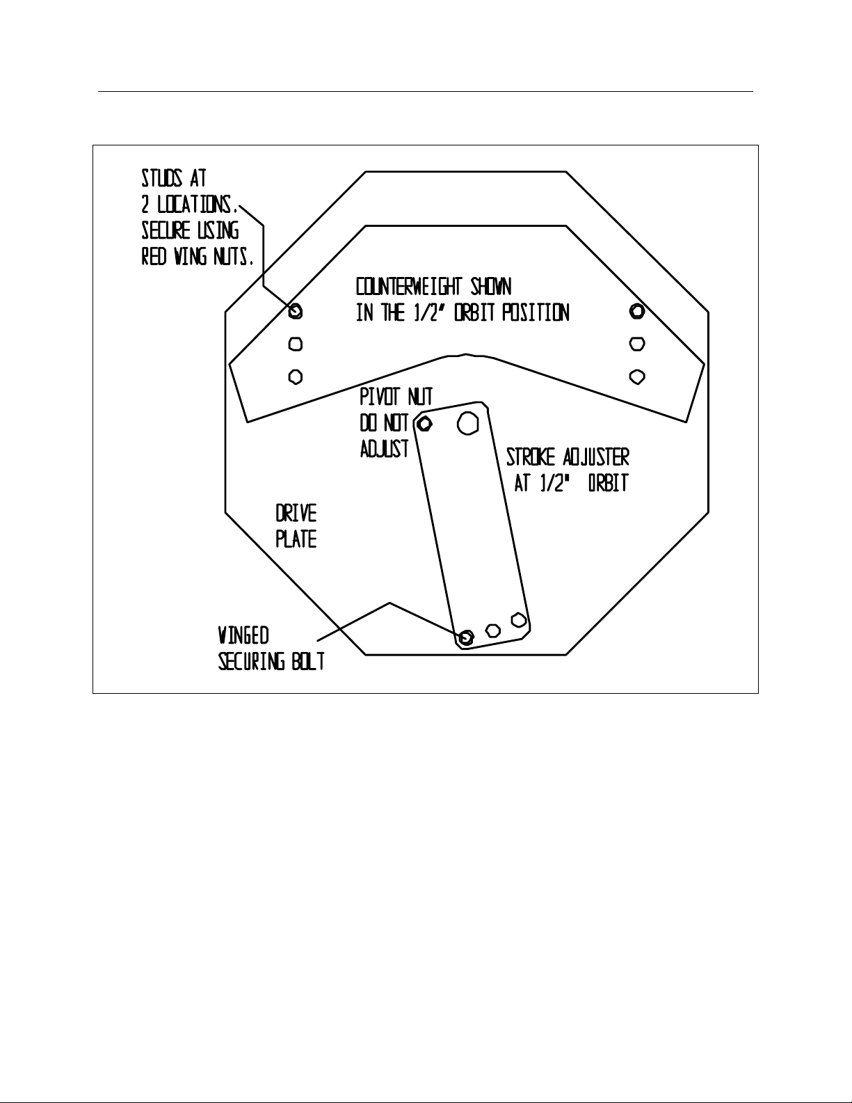
Table 3 shows counterbalance starting locations. For example, 5 kg of sample load being shaken with ½
inch stroke will require four counterweights attached to the counterbalance platform as shown in Figure 3.
Loads should be properly counterbalanced before continuous operation. Unbalanced loading may
damage mechanical and electrical operating systems.
Table 3. Counterbalance Starting Locations
No Load 5 kg of samples 10 kg of samples
Counterweights 2 4 6
For ½” stroke See Figure 3 See Figure 3 See Figure 3
For ¾” stroke See Figure 4 See Figure 4 See Figure 4
For 1” stroke See Figure 5 See Figure 5 See Figure 5
Note: Each unit includes six (6) single counterweights when shipped.
Orbital Shaking Incubator 17
Artisan Technology Group - Quality Instrumentation ... Guaranteed | (888) 88-SOURCE | www.artisantg.com
Page 19
6
Figure 3. Setup for ½ Inch Stroke
18 Orbital Shaking Incubator
Artisan Technology Group - Quality Instrumentation ... Guaranteed | (888) 88-SOURCE | www.artisantg.com
Page 20
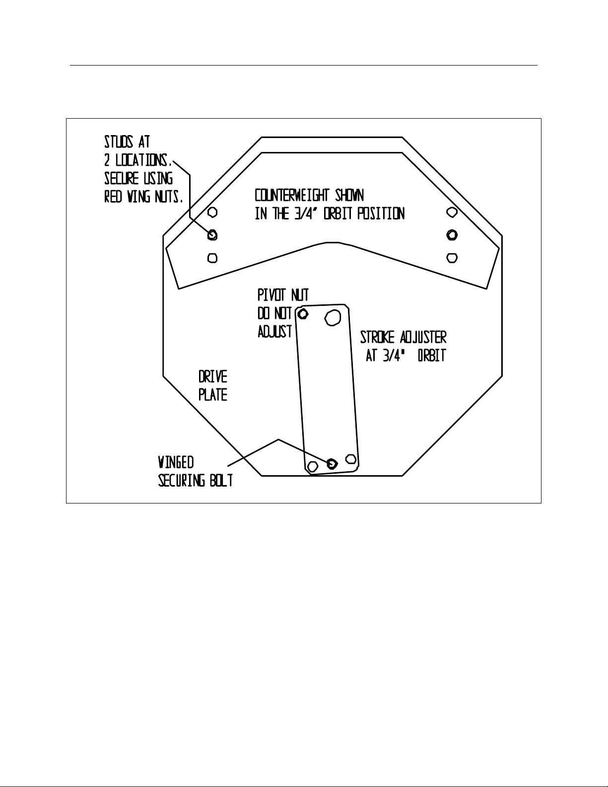
Figure 4. Setup for ¾ Inch Stroke
6
Orbital Shaking Incubator 19
Artisan Technology Group - Quality Instrumentation ... Guaranteed | (888) 88-SOURCE | www.artisantg.com
Page 21
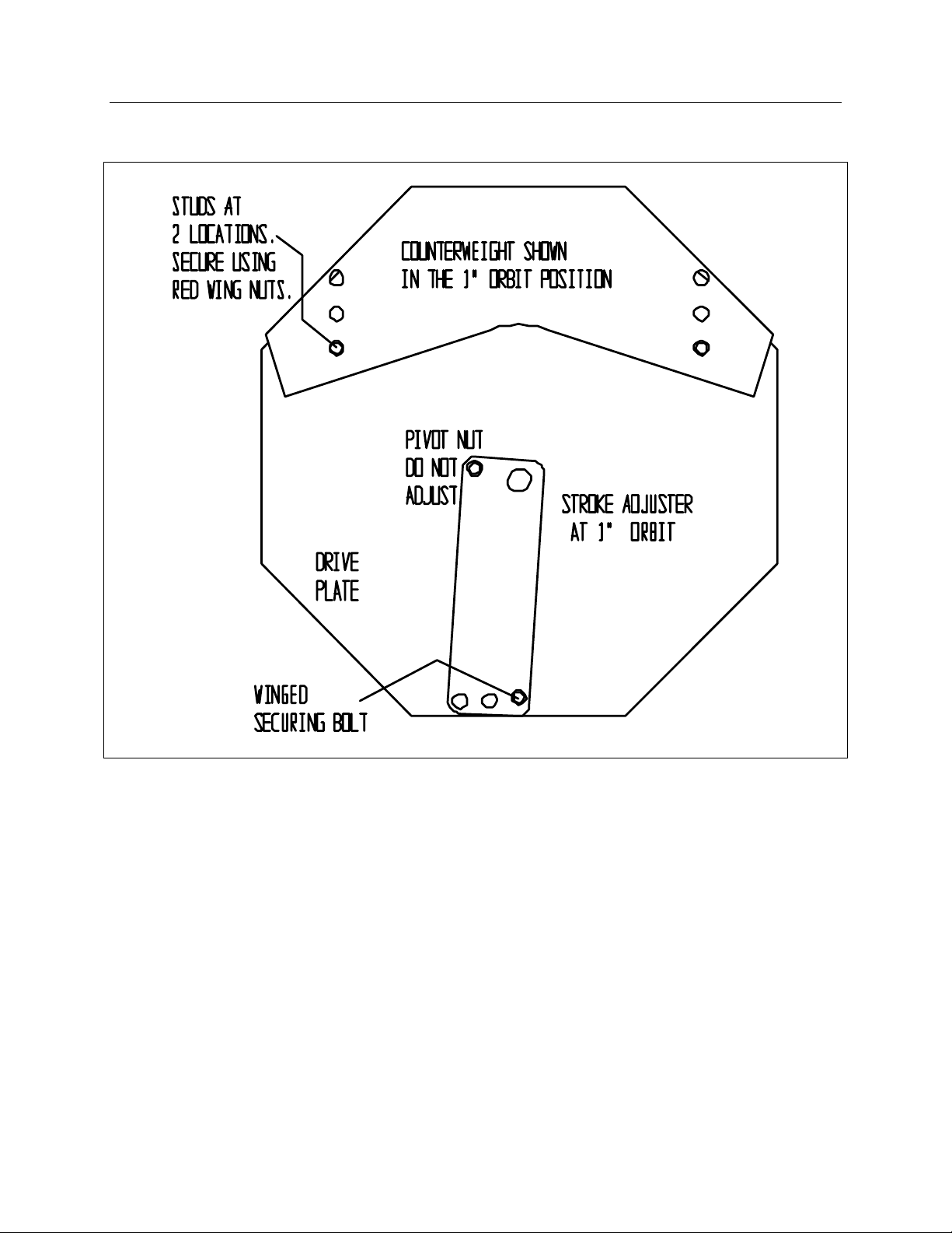
6
Figure 5. Setup for 1 Inch Stroke
20 Orbital Shaking Incubator
Artisan Technology Group - Quality Instrumentation ... Guaranteed | (888) 88-SOURCE | www.artisantg.com
Page 22

6
Interior Accessory Outlet
This unit features an accessory outlet to provide power for equipment such as magnetic stirrers, rockers,
etc. The weight of this equipment should not exceed 25 pounds (55.125 kg) per shelf. This equipment
may provide additional heat that could affect the temperature range of this incubator. We recommend
testing the incubator and any accessory equipment to ensure that the desired operating conditions can be
met.
Caution: This incubator operates at conditions that might damage accessory equipment. Verify that
your accessory equipment is capable of operating under the same conditions as the incubator.
The outlet is located inside the incubator in the upper right rear of the chamber. The voltage available at
the accessory outlet is the SAME as the voltage supplied to the incubator. For example, a 120-vac
incubator will have 120 vac at the accessory outlet, and a 240-vac incubator will have 240 vac at the
accessory outlet. DO NOT exceed 500 va rating of the accessory outlet.
Orbital Shaking Incubator 21
Artisan Technology Group - Quality Instrumentation ... Guaranteed | (888) 88-SOURCE | www.artisantg.com
Page 23

Section
MAINTENANCE
Warning: Prior to any maintenance or service on this unit, disconnect the power cord from the power
supply. Before reattaching the unit to its power supply, be sure all volatile and flammable
cleaners are evaporated and dry.
Cleaning
Note: The unit chamber should be cleaned and disinfected prior to use.
Periodic cleaning is required. To clean the incubator, perform the following steps:
1. Remove all of the interior parts, if assembled.
2. Clean the incubator with a mild soap and water solution, including all corners.
DO NOT USE spray cleaners that might leak through openings and cracks and get on electrical
components, or that may contain solvents that will harm coatings. DO NOT USE chlorine-based
bleaches or abrasives, as they will damage the stainless steel interior.
3. Rinse with distilled water and wipe dry with a soft cloth.
Disinfecting
Disinfect the incubator on a regular basis. To disinfect the incubator, perform the following steps.
1. Remove all of the interior parts, if assembled. The fan blade is replaceable. Stainless steel parts are
autoclavable.
2. Disinfect the incubator using a suitable disinfectant. When washing the interior, handle the gasket
carefully so as not to impair the positive seal. Decontamination of the shaker mechanism should be
done in place if possible. If further disassembly is desired, call customer service.
DO NOT USE spray cleaners that might leak through openings and cracks and get on electrical
components, or that may contain solvents that will harm the coatings. DO NOT USE chlorine-based
bleaches or abrasives, as they will damage the stainless steel interior. Special care should be taken
when cleaning around sensing heads to prevent damage and around the door gasket so as not to
impair the positive seal.
Controls
There is no maintenance required on the main temperature controller, Overtemperature Thermostat or
main temperature probe. If the incubator fails to maintain temperature, see TROUBLESHOOTING,
before calling customer service.
Orbital Shaking Incubator 22
Artisan Technology Group - Quality Instrumentation ... Guaranteed | (888) 88-SOURCE | www.artisantg.com
Page 24

Section
TROUBLESHOOTING
Should the unit malfunction, use this section to determine the problem and resolution. Troubleshooting
topics include:
• Temperature
• Refrigeration (1575R only)
• Mechanical
• Other
Warning: Troubleshooting procedures involve working with high voltages that can cause injury or death.
Troubleshooting should be performed only by trained personnel.
Table 4. Temperature Troubleshooting
Problem Possible Cause Solution
Temperature too high. The
display and reference
thermometer do not match
Display reads “HI” or “400”+
Chamber temperature spikes
over set point and then settles
to set point
Temperature too low; display
and reference thermometer do
not match
Controller set too high See Setting the Main Temperature Control.
Controller failed on Call customer service.
Wiring error Call customer service.
Probe is unplugged Trace wire from display to probe, move wire, and
Probe is broken
Wire to sensor is broken
N/A Recalibrate. See Calibrating the Main
Overtemperature set too low Turn thermostat fully clockwise
Controller set too low See Setting the Main Temperature Control.
Unit not recovered from door
opening
Unit not recovered from power
failure or being turned off
Element failure See if HEATING light is on; compare current draw
Controller failure Confirm with front panel lights that controller is
Thermostat failure Confirm with front panel lights that
watch display to see intermittent problems.
Call customer service.
Call customer service.
Temperature Control.
Wait for display to stop changing.
Incubators will need 24 hours to warm up and
stabilize.
to data plate.
calling for heat.
23 Orbital Shaking Incubator
Artisan Technology Group - Quality Instrumentation ... Guaranteed | (888) 88-SOURCE | www.artisantg.com
Page 25

8
Problem Possible Cause Solution
Overtemperature is operating correctly.
Wiring problem Check all functions and compare wiring to the
owner’s manual, especially around any areas
recently worked on.
Loose connection Call customer service.
Display reads "LO"
Unit will not heat over a
temperature that is below set
point
Unit will not heat up at all
Ambient temperature is lower
than range of unit
Sensor is plugged in backwards Call customer service.
N/A Confirm that fan is moving and that amperage and
N/A Confirm that set point is set high enough. Turn
N/A Check connections to sensor.
N/A Check calibration. Using an independent
N/A Verify that controller is asking for heat by looking
N/A Check amperage. Amperage should be virtually at
N/A Do all controller functions work?
N/A Is the Overtemperature Thermostat set high
N/A Has the fuse or circuit breaker blown?
Compare set points and ambient temperature to
rated specifications in UNIT SPECIFICATIONS.
voltage match data plate. Check fan motor motion
by removing back body panel of the unit.
Overtemperature all the way clockwise and see if
HEATING light or OVERTEMP light comes on.
thermometer, follow instructions in Calibrating the
Main Temperature Control.
for HEATING light. If pilot light is not on
continuously during initial start up, there is a
problem with the controller.
maximum rated (data plate) amperage.
enough? For diagnostics, the Overtemperature
Thermostat should be fully clockwise, and the
Overtemperature light should not be on.
Indicated chamber temperature
unstable
N/A ±0.1 may be normal.
N/A Is the fan working? Remove back panel and verify
movement of cooling fan.
N/A Is ambient temperature radically changing? The
door opening, room airflow from heaters, or air
conditioning may be destabilizing temperature.
Stabilize ambient conditions.
Sensor miss-located or
damaged or wires may be
damaged.
Calibration sensitivity Call customer service.
Overtemperature set too low Ensure that the incubator setting is more than 5
Check mounts for control and Thermostat
sensors, then trace wires or tubing between
sensors and controls.
degrees over desired set point. Check if pilot light
is on continuously. Turn the controller knob
completely clockwise to see if the problem is
solved, then follow instructions in Setting the Main
24 Orbital Shaking Incubator
Artisan Technology Group - Quality Instrumentation ... Guaranteed | (888) 88-SOURCE | www.artisantg.com
Page 26

Problem Possible Cause Solution
Will not maintain set point
Display and reference
thermometer do not match
8
Temperature Control for correct setting.
Electrical noise Remove nearby sources of RFI including motors,
arcing relays or radio transmitters.
Bad connection on temperature
sensor or faulty sensor
Bad connections Check connectors for mechanical soundness and
N/A Assure that set point is at least 5 degrees over
N/A See if ambient is fluctuating. Check for adjacent
Calibration error See Calibrating the Main Temperature Control.
Temperature sensor failure Evaluate if pilot light is operating correctly.
Controller failure Evaluate if pilot light is operating correctly.
N/A Allow at least 24 hours to stabilize at set point
N/A Verify that reference thermometer is certified.
Check connectors for continuity and mechanical
soundness while watching display for erratic
behavior. Check sensor and wiring for mechanical
damage.
look for corrosion around terminals or signs of
arcing or other visible deterioration.
ambient.
open doors or HVAC duct openings, stabilize
ambient conditions.
temperature.
Can not adjust set points or
calibration
Calibrated at one temperature
but not at another
Note: N/A is not available.
N/A Turn entire unit off and on to reset.
N/A If repeatedly happens, call customer service.
N/A This can be a normal condition when operating
temperature varies widely. For maximum
accuracy, calibration should be done at or as
close to the set point temperature as possible.
Orbital Shaking Incubator 25
Artisan Technology Group - Quality Instrumentation ... Guaranteed | (888) 88-SOURCE | www.artisantg.com
Page 27

8
Table 5. Refrigeration Troubleshooting (R Suffix Models Only)
Problem Possible Cause Solution
N/A Assure that power is going to heating coils Temperature will not reach set
point
N/A
Confirm that controller is calling for heat (check
front panel light)
Unit will not cool
Ice build up in chamber
Probe is unplugged If the compressor is running:
• See if condenser is cold but free of ice
• Confirm proper sensor location and operation
• Look for leaks in the chamber or around the
door gasket
• Assure ample room around the unit as
described in manual – 5 cm (2 inches) minimum
• Adjust calibration on controller
• Compare ambient specifications to
specifications in the manual
• Call customer service
N/A If compressor isn’t running:
• See if refrigeration is running too hot and
thermal cutoff activated
• Dirty coil or poor circulation
• Coil next to heat source
• Ambient temperature too high
N/A Look for leak in door gasket
N/A Door open too often
N/A Open container inside the chamber
N/A Check tightness of seal around all chamber wire
and plumbing access to outside
Making noise Steady internal clicking may
indicate a broken spring or
valve.
Call customer service.
Note: N/A is not available.
26 Orbital Shaking Incubator
Artisan Technology Group - Quality Instrumentation ... Guaranteed | (888) 88-SOURCE | www.artisantg.com
Page 28

8
Table 6. Mechanical Troubleshooting
Problem Possible Cause Solution
N/A Stretch and tuck gasket.
N/A Align clamps till they hold gasket tight.
N/A Check physical condition of gasket.
Door not sealing
N/A Tighten door latch until it pulls door tightly closed.
N/A Assure that gasket clamps are in original location.
N/A
Adjust hinge blocks or twist the door
Water leaking
Shaker motor noise
Note: N/A is not available.
N/A
N/A If leaking inside:
N/A If leaking outside:
N/A Continuous squealing noise of a constant pitch or tone. Changes
N/A If noise is from the shaft or fan blade, realign the shaft.
Confirm that unit has not been damaged and body is not out of
square
• Dry chamber
• Run at temperature with door open.
• Check all seams with flashlight including front face
• Dry out and see if leak repeats and find source of leak.
• Sources may include: fittings that need tightening,
condensation due to missing insulation or a leak developed in
compressor compartment
only in intensity for various rpm settings. Stops when the oscillate
switch is turned off. Appears to be coming directly from the
motor, not the mechanism or gear box:
• Make sure the motor cable plugs are properly seated
• Replace the speed control
Orbital Shaking Incubator 27
Artisan Technology Group - Quality Instrumentation ... Guaranteed | (888) 88-SOURCE | www.artisantg.com
Page 29

8
Table 7. Miscellaneous Troubleshooting
Problem Possible Cause Solution
N/A Turn unit off and on to reset. Controller on at all times and is
"locked-up"
Controller timer resets on its own
N/A If you cannot change any condition on the front panel, call
customer service.
N/A Confirm that power from wall is consistent and within
specifications.
N/A Call customer service with serial number.
Unit or wall
fuse/circuit
breaker is blown.
Front panel displays are all off
Unit will not turn on
Unit is smoking out of the box N/A This is not an uncommon occurrence when first operating new
N/A Check wall power source.
N/A Compare current draw and compare to specs on data plate.
N/A See what other loads are on the wall circuit.
N/A Check wall power source.
N/A Check fuse/circuit breaker on unit or in wall.
N/A Check all wiring connections, especially around the on/off
N/A See if unit is on (fan or heater), and just controller is off.
N/A See Cleaning and Disinfecting sections. Contamination in chamber
N/A Develop and follow standard operating procedure for specific
Check for wire damage.
switch.
units. Put unit under vent and run at full power for one hour.
Smoking is normal during first cycle to temperature.
application. Include definition of cleaning technique and
maintenance schedule.
Note: N/A is not available.
28 Orbital Shaking Incubator
Artisan Technology Group - Quality Instrumentation ... Guaranteed | (888) 88-SOURCE | www.artisantg.com
Page 30

Section
PARTS LIST
Table 8. Parts
Part Description 115 V Part Numbers 220 V Part Numbers 220 V “CE”
Adjustable feet 2700506 2700506 2700506
Control, Mother Board 1750716 1750716 1750716
Counterweight, Single 5460662 5460662 5460662
Display, RPM 1750731 1750731 1750731
Display, Temperature 1750677 1750677 1750677
Door Gasket 3450527 3450527 3450527
Drive Belt, Oscillator 0500512 0500512 0500512
Element 9570703 9570738 9570738
EMI Filter NA NA 2800502
Flask Clamps, 1 Liter 9530532 9530532 9530532
Flask Clamps, 125 ml 9530530 9530530 9530530
Flask Clamps, 250 ml 9530531 9530531 9530531
Flask Clamps, 500 ml 9530526 9530526 9530526
Fuse Holder 3300501 3300501 3300501
Fuse, non-refrigerated units 3300513 3300515 3300515
Fuse, refrigerated Units 3300513 3300513 3300513
IEC Inlet NA NA 4200505
Knob, Safety Thermostat 4450506 4450506 4450506
Light Ballast 4660501 4660504 4660504
Light Cover 9510502 9510502 9510502
Light Cover Gasket 3450538 3450538 3450538
Light Fluorescent 4650528 4650528 4650528
Light Holder 4660502 4660502 4660502
Motor, Cable 0860503 0860503 0860503
Motor, Circulation 4880527 4880528 4880528
Motor, Oscillator 4880514 4880514 4880514
Pilot Light, Green 200021 200021 200021
Pilot Light, Red 200020 200020 200020
Orbital Shaking Incubator 29
Artisan Technology Group - Quality Instrumentation ... Guaranteed | (888) 88-SOURCE | www.artisantg.com
Page 31

9
Part Description 115 V Part Numbers 220 V Part Numbers 220 V “CE”
Platform (Sample Tray) 5220625 5220625 5220625
Power Cord 1800516 101990 Detachable
Refrigeration Unit, 1575R 7010521 7010543 7010543
Safety Thermostat 10000J 10000J 10000J
Shelf 5100531 5100531 5100531
Shelf Clips 200137 200137 200137
Switch, Door X1000022 X1000022 X1000022
Switch, Osc, Light, and Accy. X1000124 X1000124 X1000124
Switch, Power 103351 103351 103351
Transformer “R” Models NA 100055 100055
Transformer, Speed Control 8350509 8350509 8350509
30 Orbital Shaking Incubator
Artisan Technology Group - Quality Instrumentation ... Guaranteed | (888) 88-SOURCE | www.artisantg.com
Page 32

Section
UNIT SPECIFICATIONS
Table 9. Temperature
Model Range Uniformity Sensitivity Alarms
1575
1575R
Table 10. Capacity
Ambient +/-1C° to 37°C
Ambient +9F° to 158°F
Ambient -20°C to 70°C (>0°C)
Ambient -36°F to 158°F (>32°F)
+
.5°C 0.1°C
+
.5°C 0.1°C
Visual Safety Lamps
Visual Safety Lamps
Model Volume Standard Shelves Shelf Dimensions Max. Number of Shelves
1575 167 L
5.8 CF
1575R 167 L
5.8 CF
Table 11. Dimensions
Model Interior (WxDxH) Exterior (WxDxH)
1575 48 cm x 51 cm x 66 cm
1575R 48 cm x 51 cm x 66 cm
19 in. x 19.25 in. x 23.5 in.
19 in. x 19.25 in. x 23.5 in.
2 47 cm x 47 cm
18.5 in. x 18.5 in.
2 47 cm x 47 cm
18.5 in. x 18.5 in.
58 cm x 69 cm x 105 cm
23.5 in. x 28.5 in. x 40.5 in.
58 cm x 69 cm x 105 cm
23.5 in. x 28.5 in. x 40.5 in.
16
16
Orbital Shaking Incubator 31
Artisan Technology Group - Quality Instrumentation ... Guaranteed | (888) 88-SOURCE | www.artisantg.com
Page 33

10
Table 12. Shaking Mechanism
Feature 1575 1575R
Motor brushless DC brushless DC
Speed, Sample 30 to 400 rpm 30 to 400 rpm
Speed Control PID Digital
Orbit Diameter 12, 19, or 25 mm 12, 19, or 25 mm
Max Sample Wt. 10 kg (limited by stroke)
Door Switch Yes Yes
Platform Dimensions 44 cm x 44 cm
½ in., 3/4 in., or 1 in.
22 lbs.
17.3 in. x 17.3 in.
PID Digital
1/2 in., 3/4 in., or 1 in.
10 kg (limited by stroke)
22 lbs.
44 cm x 44 cm
17.3 in. x 17.3 in.
Table 13. Refrigeration
Model Compressor Type Refrigerant
1575 NA N/A
1575R 1/6 HP R-134A
Note: N/A is not available.
Table 14. Electrical
Model Volts Hz Amperage
1575 120V / 240V 50/60 Hz 8.5 / 5.5
1575R 120V / 240V 50/60 Hz 11.5 / 7
32 Orbital Shaking Incubator
Artisan Technology Group - Quality Instrumentation ... Guaranteed | (888) 88-SOURCE | www.artisantg.com
Page 34
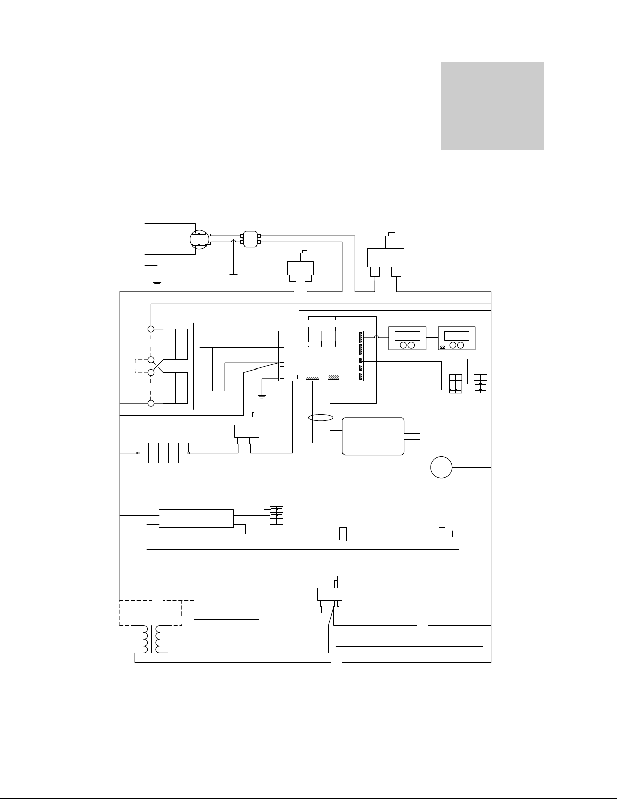
SCHEMATICS
Figure 6. Wire Diagram
Section
230
H
N
G
120
120
ELEMENT
9570893 - 120V
9570894 - 230V
POWER
ON/OFF
7850532
8350509
Black
120V/
75VA
Black / White
Black / Violet
120V/
75VA
Black / Yellow
4660501 — 120V
4660506 — 240V
I
BALLAST
Yellow
Yellow
150VA
EMI FILTER
‘CE’ Models
2800502
O
230V
Models
15A
ORNBRN
RED
1750716
ENCODER
0860503
CABLE
BUSS
BUSS
0-1V
TEMP
TACH
HOT
PHA PHB PHC
POD
HV
X1000124
TEMP/SPEED
HALLS
FLUORESCENT LIGHT IS NOT AVAILABLE ON THE 1570
N
O
OTP
CONTROL
10000J
NEUT
HEAT HOT
GND
90V/
N
C
C
Bodine
Motor
4880514
15A
1100505 CIRCUIT BREAKER
3300501 FUSE HOLDER
1750677
TEMP DISP
37.0 100
F15-T8
4650528
9850997
SOME MODELS MAY USE FUSE HOLDERS
HOLDER: 3300501 1/120V, 2/230V.
16A: 3300513 1/120V, 2/230V REFRIG.
16A: 3300513 1/120V REFRIG.
6.3A: 3300515 2/230V.
OR
1750731
RPM DISP
FAN
CH
OSC SW
ON/OFF
X1000124
CHAMBER FAN
4880527 — 120V
4880528 — 240V
DOOR SW
X1000022
110-240V
230V
120V
230V
100055 TRANSFORMER
PART OF 230V
REFRIGERATION UNIT
REFRIGERATION
UNIT
9990583 - 120V
9990617 - 230V
C
230V
PART OF
REFRIGERATION
N
N
UNIT
C
O
10000J
120V
REFRIGERATION UNIT IS NOT AVAILABLE ON THE 1570
230V
B
Orbital Shaking Incubator 33
Artisan Technology Group - Quality Instrumentation ... Guaranteed | (888) 88-SOURCE | www.artisantg.com
Page 35

10
SHELDON MANUFACTURING, INC.
LIMITED WARRANTY
Sheldon Manufacturing, Inc., (“Manufacturer”) warrants for the original user of this product in the U.S.A.
only that this product (parts only if outside of the U.S.A.) will be free from defects in material and
workmanship for a period of two years from the date of delivery of this product to the original user (the
“Warranty Period”). During the Warranty Period, Manufacturer, at its election and expense, will repair or
replace the product or parts that are proven to Manufacturer’s satisfaction to be defective, or, at
Manufacturer’s option, refund the price or credit (against the price of future purchases of the product) the
price of any products that are proven to Manufacturer’s satisfaction to be defective. This warranty does
not include any labor charges if outside of the U.S.A. This warranty does not cover any damage due to
accident, misuse, negligence, or abnormal use. Use of Manufacturer’s product in a system that includes
components not manufactured by Manufacturer is not covered by this warranty. This warranty is void in
the event that repairs are made by anyone other than Manufacturer without prior authorization from
Manufacturer. Any alteration or removal of the serial number on Manufacturer’s products will void this
warranty. Under no circumstances will Manufacturer be liable for indirect, incidental,
consequential, or special damages. The terms of this warranty are governed by the laws of the state of
Oregon without regards to the principles of conflicts of laws thereof. If any provision of this limited
warranty is held to be unenforceable by any court of competent jurisdiction, the remainder of this limited
warranty will remain in full force and effect.
This warranty is in lieu of and excludes all other warranties or obligations, either express or
implied. Manufacturer expressly disclaims all implied warranties, including without limitation, the
warranties of merchantability and fitness for a particular purpose.
For fast and efficient support, please have the following information available anytime you request
service:
Model __________
Serial No. __________
Part No. __________
34 Orbital Shaking Incubator
Artisan Technology Group - Quality Instrumentation ... Guaranteed | (888) 88-SOURCE | www.artisantg.com
Page 36

Order From VWR
e
Call 800-932-5000
from anywhere in the U.S. and Canada
Sales & Inventory Locations:
8
Pacific Northwest Ar
Anchorage, AK
Salt Lake City, UT
San Francisco, CA
Seattle, WA
Tualatin, OR
Southwest Area
Albuquerque, NM
Denver, CO
Phoenix, AZ
San Diego, CA
San Dimas, CA
Midwest Area
Chicago, IL
Detroit, MI
Indianapolis, IN
Minneapolis, MN
St. Louis, MO
Gulf Area
Austin, TX
Dallas, TX
Houston, TX
Lake Charles, LA
Northeast Area
Boston, MA
Cincinnati, OH
Cleveland, OH
Pittsburgh, PA
Rochester, NY
Mid-Atlantic Area
Baltimore, MD
Branford, CT
Bridgeport, NJ
S. Plainfield, NJ
Southeast Area
Atlanta, GA
Oak Ridge, TN
VWR Canlab Offices
Mississauga, Ontario
Ville Mont-Royal, Québec
Edmonton, Alberta
Or Call Direct for Specialized Service Locations:
VWR International
3000 Hadley Rd
S. Plainfield, NJ 07080
(908) 757-4045
fax: (908) 757-0313
Puerto Rico
Carr. #869 Km. 1.5 M4
Royal Industrial Park
Catano, PR 00962
(787) 788-3222
fax: (787) 78804320
Switzerland
Ruchligstrasse # 20
P.O. Box 464
Dietikon, Switzerland
CH-8953
011-41-1-745-1155
fax: 011-41-1-745-1150
VWR Direct
911 Commerce Ct.
Buffalo Grove, IL 60089
(800) 444-0880
VWR Furniture Division
P.O. Box 3405
Irving, TX 75015
(972) 714-0336
VWR National Accounts
1310 Goshen Pkwy
W. Chester, PA 19380
(610) 431-1700
Visit Our Web Site at
http://www.vwrsp.com
Orbital Shaking Incubator 35
Artisan Technology Group - Quality Instrumentation ... Guaranteed | (888) 88-SOURCE | www.artisantg.com
Page 37

Artisan
Technology
Group
is
an independent supplier
of
quality pre-owned equipment
Gold-standard
Extend the life
commercial, and military systems
superior service and support.
Artisan Scientific
of
your
Corporation
solutions
critical industrial,
dba
Artisan
Technology
with
Group
our
We're here to make your life easier.
(217)
352-9330
I [email protected] I artisantg.com
We
buy
equipment
Planning to
equipment? Have surplus equipment taking
up shelf space? We'll give it a
is
not
an affiliate,
How
can
upgrade
representative,
we
or
help you today?
your current
authorized
distributor
new
for
home.
any
manufacturer
Learn
Visit us at artisantg.com for more info
on price quotes, drivers, technical
specifications, manuals, and documentation.
listed herein.
more!
 Loading...