

Page 1

VWR® Thermometer
North American Catalog Numbers: 61161-283, 46610-024,
15551-004, 12777-842, 89172-082, 89172-084
European Catalogue Numbers: 620-2017, 620-2073, 620-2092,
620-2099, 620-1826
Version: 1
Issued: 3
rd
November 2014
INSTRUCTION MANUAL
VWR Collection Manual ver 3, rel 5 30.10.2013
Page 2

Legal Address of Manufacturer
United States Europe
VWR International VWR International bvba
Radnor Corporate Center Researchpark Haasrode 2020
Building One, Suite 200 Geldenaaksebaan 464
100 Matsonford Road, P.O. Box 6660 B-3001 Leuven
Radnor, PA 19087 + 32 16 385011
800-932-5000 http://be.vwr.com
http://www.vwr.com
Country of Origin – Hong Kong
INTENDED USE
This item is intended for general laboratory use to monitor temperature.
VWR TRACEABLE® STAINLESS-STEEL PROBES THERMOMETER INSTRUCTIONS ENGLISH
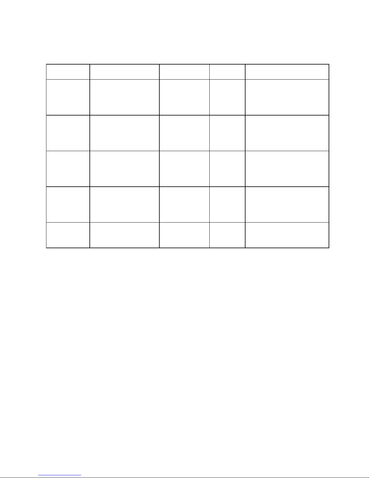
SPECIFICATIONS
Cat. No. Range Resolution Accuracy Probe
61161-283/
620-2017
–58 to 572°F
(–50 to 300°C)
0.1° from –
20° to 200°,
1° otherwise
±1.0°C
between
–20 and 100°C
stainless steel-probe
diameter 0.14 inch, length 5
inches
46610-024/
620-2073
–58 to 572°F
(–50 to 300°C)
0.1° from –
20° to
200°,1°
otherwise
±0.5°C at
tested points
stainless steel-probe
diameter 0.14 inch, length 5
inches
15551-004/
620-2092
–58 to 572°F
(–50 to 300°C)
0.1° from –
20° to 200°,
1° otherwise
±1.0°C
between
–20 and 100°C
Stainless-steel 0.14-inch;
stem length, 8 inches; overall
length, 10-1/4 inches
12777-842
620-2099
–58 to 572°F
(–50 to 300°C)
0.1° from –
20° to
200°,1°
otherwise
±0.4°C at
tested points
Stainless-steel 0.14-inch;
stem length, 8 inches; overall
length, 10-1/4 inches
89172-082/
620-1826
–22 to 122°F and
–30 to 50°C
0.1° ±1.0°C Sealed bottle Probe
89172-084
–22 to 122°F and
–30 to 50°C
0.1° ±0.4°C at
tested points
Sealed bottle Probe
VWR Collection Manual ver 3, rel 5 30.10.2013
Page 3

ULTRA™ THERMOMETER ACCURACY
Ultra™ thermometers are tested at selected test points to be within tighter than normal tolerances to assist in
providing improved accuracy. Other points will not necessarily fall within the same accuracy as those found at
the selected test points, but will be within an accuracy of ±1°C.
CAT. NO. 61161-283/620-2017; 46610-024/620-2073 (CA B LE WITH STAINLESS-STEEL PROBE)
CAT. NO. 15551-004/620-2092; 12777-842/620-2099 (STAINLESS-STEEL PROBE)
CAT. NO. 89172-082/620-1826; 89172-084 (SEALED BOTTLE PROBE FOR REFRIGERATOR/FREEZER
APPLICATIONS)
OPERATION
1. Press the ON/OFF button to turn the unit on. Press the °F/°C button to switch between Fahrenheit and
Celsius.
2. Insert the probe into the material to be measured and read the display.
3. Press the ON/OFF button to turn the unit off. To conserve battery life, always turn the unit off when not in
use.
MAX/MIN MEMORY
1. To view the minimum temperature reached since activating the unit, press the MAX/MIN button. “MIN”
appears on the display to indicate the minimum temperature recorded.
2. Press the MAX/MIN button a second time, within 3 seconds, to view the maximum temperature reached
since activating the unit. “MAX” appears on the display to indicate the maximum temperature recorded.
Note:
Three seconds after pressing the MAX/MIN button, the unit automatically returns to the current
temperature reading. (“MIN” and “MAX” are no longer displayed.)
3. Turn the unit off to reset the minimum and maximum memories.
Cat. No. 89172-082/620-1826; 89172-084 IMPORTANT: The intended use for this thermometer is to
monitor temperatures inside refrigerators and freezers.
The entire unit is completely sealed and waterproof. Do not attempt to remove the thermometer from the bottle.
Velcro
®
and double sided foam tape are supplied and may be used to mount the thermometer or the base side
to any surface. In a refrigerator application, this prevents the thermometer from taking up valuable shelf space.
Cat. No. 89172-082/620-1826; 89172-084 USING THE MEMORY TO MONITOR A REFRIGERATOR
/FREEZER
Following is an example of how to use the memory to monitor the temperature inside a refrigerator or freezer.
This example is provided only as a helpful guide and is not intended to replace existing facility requirements or
procedures.
VWR Collection Manual ver 3, rel 5 30.10.2013
Page 4

Unit Setup Example
1. Turn the unit on.
2. Select the desired unit of measure.
3. Place the thermometer into the supplied base.
4. Place the thermometer and base inside the refrigerator/freezer.
At this point, allow sufficient time for the bottle thermometer to reach equilibrium with the true current
temperature inside the refrigerator/freezer.
5. Once the thermometer has reached equilibrium, clear the minimum and maximum temperature memory. (See
the “Minimum/Maximum Memory” section.)
The memory will provide a record of the single lowest and highest temperature achieved. When the
temperatures are recorded into the manual log, the memory will allow the user to see if the temperature inside
the refrigerator/freezer has gone outside of the acceptable range.
MONITORING PROCEDURE EXAMPLE
Keep a notebook or spreadsheet as a manual log.
1. At the same time every day, record the following into the manual log:
• Current Date and Time
• Current Temperature Reading
• Minimum Temperature Reading (MIN)
• Maximum Temperature Reading (MAX)
2. Once the above items have been manually recorded, clear the minimum and maximum temperature
memory. (See the “Minimum/Maximum Memory” section.)
By clearing the memory each day, the minimum and maximum temperature memory will provide a record of
the minimum and maximum temperature that has been achieved inside the refrigerator/freezer over the past
24 hour monitoring period. The memory will also allow the user to see if the temperature inside the refrigerator
went outside of the acceptable range.
ALL OPERATIONAL DIFFICULTIES
If this thermometer does not function properly for any reason, replace the battery with a new high quality
battery (see the “Battery Replacement” section). Low battery power can occasionally cause any number of
“apparent” operational difficulties. Replacing the battery with a new fresh battery will solve most difficulties.
BATTERY REPLACEMENT
Erratic readings, a faint display, no display, or [===] appearing on the display are all indications that the
battery must be replaced. To replace the battery, remove the three battery cover screws located on the back
of the unit. Remove the battery cover. Replace the exhausted battery with a new 1.5-volt, silver oxide, #357
size battery. Make certain the positive (+) side is visible. Replace the battery cover and battery cover screws.
Do not overtighten the screws as this may damage the unit.
NOTE:
When replacing the battery cover, ensure the screws are tightened securely to maintain the unit’s
water-proof seal.
VWR Collection Manual ver 3, rel 5 30.10.2013
Page 5

Technical service
Web Resources
Visit the VWR’s website at www.vwr.com for:
• Complete technical service contact information
• Access to VWR’s Online Catalogue, and information about accessories and related products
• Additional product information and special offers
Contact us for information or technical assistance contact your local VWR representative or visit. www.vwr.com.
Warranty
VWR International warrants that this product will be free from defects in material and workmanship for a period of
two (2) years from date of purchase. If a defect is present, VWR will, at its option, repair, replace, or refund the
purchase price of this product at no charge to you, provided it is returned during the warranty period. This
warranty does not apply if the product has been damaged by accident, abuse, misuse, or misapplication, or from
ordinary wear and tear. For your protection, items being returned must be insured against possible damage or
loss. This warranty shall be limited to the replacement of defective products. IT IS EXPRESSLY AGREED THAT
THIS WARRANTY WILL BE IN LIEU OF ALL WARRANTIES OF FITNESS AND IN LIEU OF THE WARRANTY
OF MERCHANTABILITY.
GO TO VWR.COM FOR THE LATEST NEWS, SPECIAL OFFERS AND DETAILS OF YOUR LOCAL VWR
DISTRIBUTOR
Equipment disposal
This equipment is marked with the crossed out wheeled bin symbol to indicate that this equipment must not
be disposed of with unsorted waste. Instead it's your responsibility to correctly dispose of your equipment at
lifecycle -end by handling it over to an authorized facility for separate collection and recycling. It's also your
responsibility to decontaminate the equipment in case of biological, chemical and/or radiological
contamination, so as to protect from health hazards the persons involved in the disposal and recycling of the
equipment. For more information about where you can drop off your waste of equipment, please contact your
local dealer from whom you originally purchased this equipment.
By doing so, you will help to conserve natural and environmental resources and you will ensure that your
equipment is recycled in a manner that protects human health.
Compliance with local laws and regulations
The customer is responsible for applying for and obtaining the necessary regulatory approvals or other
authorizations necessary to run or use the Product in its local environment. VWR will not be held liable for any
related omission or for not obtaining the required approval or authorization, unless any refusal is due to a
defect of the product.
VWR Collection Manual ver 3, rel 5 30.10.2013
Page 6

INSTRUCCIONES DE USO PARA TERMÓMETROS CON SONDA TRACEABLE® EN ACERO
INOXIDABLE - ESPAÑOL
CARACTERÍSTICOS
Cat. No. Rango Resolución Precisión Sonda
61161-283/
620-2017
–58 hacia 572°F
(–50 hacia 300°C)
0,1° desde –20°
hacia 200°,
sino 1°
±1,0°C entre
–20 y 100°C
Sonda en acero inoxidable de
0.35 cm (0,14 pie) de
diámetro y 12,7 cm (5 pies)
de longitud
46610-024/
620-2073
–58 hacia 572°F
(–50 hacia 300°C)
0,1° desde –20°
hacia 200°,
sino 1°
±0,5°C a los
puntos probados
Sonda en acero inoxidable de
0.35 cm (0,14 pie) de
diámetro y 12,7 cm (5 pies)
de longitud
15551-004/
620-2092
–58 hacia 572°F
(–50 hacia 300°C)
0,1° desde –20°
hacia 200°,
sino 1°
±1,0°C entre
–20 y 100°C
Acero inoxidable 0.35 cm
(0,14 pie) ; longitud del tallo:
20,32 cm (8 pies); longitud
total: 26 cm (10-1/4 pies)
12777-842
620-2099
–58 hacia 572°F
(–50 hacia 300°C)
0,1° desde –20°
hacia 200°,
sino 1°
±0,4°C a los
puntos probados
Acero inoxidable 0.35 cm
(0,14 pie) ; longitud del tallo:
20,32 cm (8 pies); longitud
total: 26 cm (10-1/4 pies)
89172-082/
620-1826
–22 hacia 122°F y
–30 hacia 50°C
0,1° ±1,0°C Sonda para frasco hermético
89172-084
–22 hacia 122°F y
–30 hacia 50°C
0,1° ±0,4°C a los
puntos probados
Sonda para frasco hermético
PRECISIÓN DEL TERMÓMETRO ULTRA™
Los termómetros Ultra™ son probados a puntos de prueba seleccionados para ficar en tolerancias más
limitadas de lo corriente, contribuyendo así en proporcionar una precisión mejor. Otros puntos no caerán
necesariamente en la misma precisión que la de los puntos de prueba seleccionados, pero serán de una
precisión de ±1°C.
CAT. NO. 61161-283/620-2017; 46610-024/620-2073 (CABLE CON SONDA DE ACERO INOXIDABLE)
CAT. NO. 15551-004/620-2092; 12777-842/620-2099 (SONDA DE ACERO INOXIDABLE)
CAT. NO. 89172-082/620-1826; 89172-084 (SONDA PARA FRASCO HERMÉTICO PARA USO EN
FRIGORÍFICOS /CONGELADORES)
FUNCIONAMIENTO
1. Pulse el botón ON/OFF para encender el dispos itivo. Pulse el botón °F/°C para alternar entre Fahrenheit
y Celsius.
VWR Collection Manual ver 3, rel 5 30.10.2013
Page 7

2. Coloque la sonda en el material que se desea medir y lea lo indicado en la pantalla.
3. Pulse el botón ON/OFF para apagar el dispositivo. Para prolongar la vida de la batería, siempre apague
el dispositivo cuando no lo utiliza.
MEMORIA MAX/MIN
1. Para visualizar la temperatura mínima alcanzada desde la activación del dispositivo, pulse el botón
MAX/MIN. Se visualiza “MIN” en la pantalla para indicar la menor temperatura registrada.
2. Pulse el botón MAX/MIN una vez más, dentro de 3 segundos, para visualizar la temperatura máxima
alcanzada desde la activación del dispositivo. Se visualiza “MAX” en la pantalla para indicar la mayor
temperatura registrada.
Nota:
Tres segundos después de pulsar el botón MAX/MIN, el dispositivo volverá a visualizar
automáticamente la temperatura actual. (“MIN” y “MAX” ya no se visualizan en la pantalla.)
3. Apague el dispositivo para reiniciar la memoria de temperaturas máxima y mínima.
Cat. No. 89172-082/620-1826; 89172-084
IMPORTANTE: Este termómetro está destinado para uso de
control de temperatura dentro de los frigoríficos y congeladores .
El dispositivo entero es totalmente sellado y impermeable. No intente extraer el termómetro del frasco.
Son proporcionados Velcro
®
y cinta de espuma de doble cara. Se pueden utilizar para montar el termómetro o
su soporte a cualquier superficie. En caso de uso en un frigorífico, éstos permiten que el termómetro no tome
espacio considerable en los estantes.
Cat. No. 89172-082/620-1826; 89172-084 USO DE LA MEMORIA PARA CONTROLAR EL
FRIGORÍFICO/CONGELADOR
Un ejemplo del modo de uso de la memoria para controlar la temperatura dentro del frigorífico o congelador
está presentado debajo. Este ejemplo es proporcionado solo como guía útil y no se destina a reemplazar
procedimientos o requisitos que ya existen para el dispositivo.
Ejemplo de instalación del dispositivo
1. Encienda el dispositivo.
2. Seleccione la unidad de medida deseada.
3. Coloque el termómetro sobre el soporte proporcionado.
4. Coloque el termómetro sobre su soporte en el frigorífico/congelador.
A este estado, deje el termómetro durante suficiente tiempo en el frasco para que alcance balance, hasta tomar
la temperatura actual en el frigorífico/congelador.
5. En cuanto el termómetro alcance balance, borre la memoria de temperaturas máxima y mínima. (Referirse
a la sección “Memoria de temperaturas Mínima/Máxima”.)
VWR Collection Manual ver 3, rel 5 30.10.2013
Page 8

La memoria proporcionara el registro de la única temperatura menor y la única temperatura mayor alcanzadas.
Cuando las temperaturas registradas son guardadas en el registro manual, la memoria permitirá al usuario
constatar si la temperatura dentro del frigorífico/congelador ha estado fuera del rango aceptable.
EJEMPLO DE PROCEDIMIENTO DE CONTROL
Mantenga un librete o hoja de calculo como registro manual.
1. Cada día, al mismo tiempo, registre los datos siguientes en su registro manual:
• Fecha y hora actuales
• Lectura de la temperatura actual
• Lectura de la temperatura mínima (MIN)
• Lectura de la temperatura máxima (MAX)
2. Una vez se haya guardado manualmente los datos encima, borre la memoria de temperaturas mínima y
máxima (Referirse a la sección “Memoria de temperaturas Mínima/Máxima”.)
Si se borra la memoria cada día, la memoria de temperaturas mínima y máxima proporcionará los valores
de la temperatura mínima y de la temperatura máxima que se haya alcanzado dentro del
frigorífico/congelador en un periodo de control de 24 horas. La memoria permitirá también al usuario,
constatar si la temperatura dentro del frigorífico/congelador ha estado fuera del rango aceptable.
TODAS LAS DIFICULTADES EN EL FUNCIONAMIENTO
Si por cualquier motivo, este dispositivo no funciona correctamente, reemplace la batería por una nueva
batería de alta calidad (referirse a la sección “Reemplazo de la batería”). La situación de batería baja puede
en ciertos casos provocar unos dificultades de funcionamiento “aparentes”.Reemplazar la batería con nueva
batería puede resolver la mayoría de las dificultades.
REEMPLAZO DE BATERÍA
Lecturas erráticas, visualización débil o ausente o aparición del símbolo [===] en la pantalla son todas signos
de que la batería debe de ser reemplazada. Para reemplazar la batería, retire los tres tornillos de la tapa de la
batería, colocados en la part e trasera del dis p ositi vo . Saq ue la tapa de la batería . Reem place la bater ía
agotada por una nueva batería de 1,5 volts en oxido de plata de tamaño #357. Asegúrese de que la cara
positiva (+) de la batería sea visible. Coloque de nuevo la tapa de la batería y los tornillos. No aprete
demasiado los tornillos ya que esto podría dañar el dispositivo.
NOTA:
Al colocar la tapa de la batería, asegúrese de que los tornillos sean apretados firmemente para
preservar el sello impermeable del dispositivo.
Servicio técnico
Recursos Web
Visite nuestro sitio web www.vwr.com
• Para direcciones completos del servicio técnico
• Para acceso al catálogo electrónico VWR y a las informaciones sobre accesorios y productos conexos.
• Y para informaciones sobre productos suplementarios y ofertas especiales.
Contáctenos
Para informaciones o asistencia técnica, contacte su representante VWR o visite el sitio web www.vwr.com.
VWR Collection Manual ver 3, rel 5 30.10.2013
Page 9

Garantía
VWR International garantiza este producto contra todos defectos de material y de fabricación durante un periodo
de dos (2) años empezando a la fecha de compra. En el caso de que haya un defecto, VWR a su discreción,
reparará, reemplazará el producto o reembolsará el precio de compra sin ningún coste para usted, siempre que
el producto sea devuelto durante el periodo de garantía. Esta garantía no tiene efecto si el producto ha sido
dañado accidentalmente, por abuso, uso o aplicación indebidos o desgaste por uso normal. Para asegurar su
protección, los productos a devolver deben de ser asegurados contra daños o perdidas. Esta garantía sera
limitada al reemplazo de productos defectuosos. QUEDA EXPRESAMENTE CONVENIDO QUE ESTA
GARANTÍA SUSTITUYE CUALQUIER OTRA GARANTÍA DE ADECUACIÓN PARA UN USO PA RTICULAR Y
LA GARANTÍA DE COMERCIABILIDAD.
VEA NUESTRO SITIO WEB VWR.COM PARA LAS ULTIMAS NOTICIAS, OFERTAS ESPECIALES Y
DIRECCIÓN DE SU DISTRIBUIDOR LOCAL
VWR Collection Manual ver 3, rel 5 30.10.2013
Page 10

INSTRUCTION POUR LES THERMOMETRES SONDES TRACEABLE® EN ACIER
INOXYDABLE - FRANÇAIS
SPECIFICATIONS
Cat. No. Champ Résolution Précision Sonde
61161-283/
620-2017
–58 à 572°F
(–50 à 300°C)
0,1° de –20° à
200°, 1°
autrement
±1,0°C entre
–20 et 100°C
Diamètre de la sonde en acier
inoxydable 0,14 pouces, longueur 5
pouces
46610-024/
620-2073
–58 à 572°F
(–50 à 300°C)
0,1° de –20° à
200°,1° autrement
±0,5°C aux points
testés
Diamètre de la sonde en acier
inoxydable 0,14 pouces, longueur 5
pouces
15551-004/
620-2092
–58 à 572°F
(–50 à 300°C)
0,1° de –20° à
200°, 1°
autrement
±1,0°C entre
–20 et 100°C
Acier inoxydable 0,14 pouces ;
longueur de la tige, 8 pouces ;
longueur totale, 10 pouces 1/4
12777-842
620-2099
–58 à 572°F
(–50 à 300°C)
0,1° de –20° à
200°,1° autrement
±0,4°C aux points
testés
Acier inoxydable 0,14 pouces ;
longueur de la tige, 8 pouces ;
longueur totale, 10 pouces 1/4
89172-082/
620-1826
–22 à 122°F et
–30 à 50°C
0,1° ±1,0°C Sonde bouteille fermée
hermétiquement
89172-084
–22 à 122°F et
–30 à 50°C
0,1° ±0,4°C aux points
testés
Sonde bouteille fermée
hermétiquement
PRECISION THERMOMETRE ULTRA™
Les thermomètres Ultra™ sont testés aux points de test choisis pour se trouver dans des tolérances plus serrées
que la normal afin de contr ibu er à fo urnir un e m eille ure préc is ion. D’a utres po ints se trou vero nt néces sa irem ent
dans la mêm e précision que ce ux trouvés aux p oints de test cho isis, mais se s itueront dans un e précision de
±1°C.
CAT. NO. 61161-283/620-2017; 46610-024/620-2073 (CABLE AVEC SONDE EN ACIER INOXYDABLE)
CAT. NO. 15551-004/620-2092; 12777-842/620-2099 (SONDE EN ACIER INOXYDABLE)
CAT. NO. 89172-082/620-1826; 89172-084 (SONDE BOUTEILLE FERMEE HERMETIQUEMENT
APPLICATIONS REFRIGERATEUR/CONGELATEUR)
FONCTIONNEMENT
1. Appuyer sur la touche ON/OFF pour mettre l’unité en marche. Appuyer sur la touche °F/°C pour passer de
Fahrenheit à Celsius.
2. Insérer la sonde dans le matériel à mesurer et lire ce qui s’afficher.
3. Appuyer sur la touche ON/OFF pour éteindre l’unité. Pour préserver la batt erie, touj our s étein dr e l’unit é
quand elle n’est pas utilisée.
VWR Collection Manual ver 3, rel 5 30.10.2013
Page 11

MEMOIRE MAX/MIN
1.Pour voir la température minimale atteinte depuis l’activation de l’unité, appuyer sur la touche MAX/MIN. “MIN”
s’affiche pour indiquer la température minimale enregistrée.
2. Appuyer sur la touche MAX/MIN une seconde f ois, dans un délai de 3 secon des, pour voir la températur e
maximale atteinte depuis l’activation de l’unité. “MAX” s’affiche pour indiquer la température maximale
enregistrée.
Note :
Trois secondes après avoir appuyé sur la touche MAX/MIN, l’unité revient automatiquement à la lecture
de la température actuelle. (“MIN” et “MAX” ne s’affichent plus.)
3. Eteindre l’unité pour restaurer les mémoires minimales et maximales.
Cat. No. 89172-082/620-1826; 89172-084
IMPORTANT : L’utilisation prévue de ce thermomètre est de
contrôler les températures dans les réfrigérateurs et congélateurs.
Toute l’unité est hermétiquement fermée et étanche. Ne pas essayer de sortir le thermomètre de la bouteille.
Le Velcro
®
et un ruban double face sont fournis et peuvent être utilisés pour fixer le thermomètre ou sa base sur
surface. En l’ ut i lis ant dans un réfrigérateur, cela é v it e qu e le t her momètre ne pren ne un espace précieux sur les
clayettes.
Cat. No. 89172-082/620-1826; 89172-084 UTILISATION DE LA MEMOIRE POUR CONTROLER UN
REFRIGERATEUR/CONGELATEUR
Ci-dessous un exemple sur la manière d’utiliser la mémoire pour contrôler la température à l’intérieur d’un
réfrigérateur ou congélateur. Cet exemple est donné uniquement à titre de guide utile et n’est pas sensé remplacer
les exigences ou procédures de l’installation.
Exemple de mise en place de l’unité
1. Allumer l’unité.
2. Sélectionner l’unité de mesure souhaitée.
3. Placer le thermomètre dans la base fournie.
4. Placer le thermomètre et la base à l’intérieur du réfrigérateur/congélateur.
A ce point, laisser suffisamment de temps au thermomètre pour atteindre un équilibre avec la température actuelle
exacte à l’intérieur du réfrigérateur/congélateur.
5. Une fois que le therm omètre a atte int l’éq uilibre, ef facer la mém oire température m inimale et maxim ale. (Cf.
Partie « Mémoire Minimale/Maximale »)
La mémoire fournira une preuve de la température la plus basse et la plus élevée atteinte. Lorsque les
températures sont enregistrées dans le livre manuel, la mémoire permettra à l’utilisateur de vérifier si la
température à l’intérieur du réfrigérateur/congélateur se situe hors des normes acceptables.
EXEMPLE DE PROCEDURE DE CONTROLE
Prendre un carnet ou une feuille de calcul à titre de livre manuel.
VWR Collection Manual ver 3, rel 5 30.10.2013
Page 12

1. A la même heure chaque jour, enregistrer les éléments ci-dessous dans le relevé manuel :
• Date et heure
• Relevé de température
• Relevé de Température Minimale (MIN)
• Relevé de Température Maximale (MAX)
2. Une fois les éléments ci-dessus enregistrés manuellement, effacer la mémoire température minimale et
maximale. (Cf. Partie « Mémoire Minimale/Maximale »)
En effaçant la mémoire tous les jours, la mémoire de tem pérature minim ale et maximale donnera un r ésultat
de température minimale et maximale atteinte dans le réfrigérateur/congélateur sur la période de contrôle des
dernières 24 heures. La mémoire permettra éga lement à l’utilisateur de voir si la températ ure à l ’int ér ieur du
réfrigérateur se situe hors des normes acceptables.
TOUS LES PROBLEMES DE FONCTIONNEMENT
Si ce thermomètre ne fonctionne pas correctement pour une raison quelconque, remplacer la pile par une
nouvelle pile de haute qualité (cf. partie « Remplacer les piles »). Une pi le faib le peut occ as ionnel lement
provoquer un certain nombre de problèmes de fonctionnement « apparents ». Le remplacement de la pile par
une nouvelle pile résoudra la plupart des problèmes.
REMPLACEMENT DE LA PILE
Des erreurs de lecture, un affichage faible, aucun affichage, ou l’apparition de [===] sur l’écran d’affichage sont
des signes que la pile doit être remplacée. Pour r emplacer la pile, retirer les tr ois vis du couvercl e de la pile
située au dos de l’unité. Retir er le couvercle de la p ile. Remplac er l’ancienne pile par une nouvelle pil e #357,
de1,5 volts, à ox yde d’ar ge nt. S ’ass ur er q ue la f ac e p o s iti ve (+) s o it vis ib le. R emettre le couvercle de la pi le et
les vis. Ne pas trop serrer les vis parce que cela pourrait endommager l’unité.
NOTE :
En remettant le couvercle de la pile, s’assurer que les vis soient bien serrées pour maintenir la
fermeture étanche de l’unité.
Service technique
Sur internet
Aller sur le site de VWR :
www.vwr.com
pour :
• remplir les informations de contact pour le service technique
• accéder au Catalogue en ligne de VWR, et aux informations concernant les accessoires et produits annexes
• informations supplémentaires sur les produits et offres spéciales
Nous contacter pour des informations ou pour une assistance technique, contacter votre agent local VWR ou aller
sur le site w ww . vw r. co m.
Garantie
VWR International garantit ce produit contre tout défaut dans le matériel et la fabrication pendant deux (2) ans à
compter de la date d’achat. S’il devait y avoir un défaut, VWR choisira soit de réparer, de remplacer ou de
rembourser le prix d’achat de ce produit gratuitement, à condition qu’il soit rapporté pendant la période de garantie.
Cette garantie ne s’applique pas si le produit a été endommagé par ac cident, mauvaise utilisation ou applicat ion,
ou par usure normale. Pour votre protection, les items retournés doivent être assurés contre les dégâts ou perte
éventuels. Cette garantie se limitera au remplacement des produits défectueux. IL EST EXPRESSEMENT
VWR Collection Manual ver 3, rel 5 30.10.2013
Page 13

CONVENU QUE LA PRESENTE GARANT IE REMPLACERA TOUTES LES GARANTIES D ’APTITUDE ET LA
GARANTIE DE QUALITE MARCHANDE.
ALLER SUR VWR.COM POUR LES DERNIERES INFORMATIONS, OFFRES SPECIALES ET DETAILS DE
VOTRE DISTRIBUTEUR VWR LOCAL
VWR Collection Manual ver 3, rel 5 30.10.2013
Page 14

TRACEABLE®BEDIENUNGSANLEITUNG FÜR D AS PRÜF-THERMOMETER AUS
ROSTFREIEM EDELSTAHL - Deutsch
TECHNISCHE ANGABEN
K
atalog. Nr.
T
emperatur-
M
essbereich
T
emperatur-
A
uflösung
M
ess-
G
enauigkeit
M
esssonde
61161
-283/
620
-2017
–
58 bis 572°F
(
–50 bis 300°C)
0.1°
von –20° bis
200°,
ansonsten 1°
±1.0°C
zwischen
–
20 und 100°C
rostfreie
Edelstahlsonde,
Durchmesser
0,3556 cm, Länge
12,7
cm
46610
-024/
620
-2073
–
58 bis 572°F
(
–50 bis 300°C)
0.1°
von –20° bis
200°,
ansonsten 1°
±0.5°C
an den
Messpunkten
rostfreie
Edelstahlsonde,
Durchmesser
0,3556 cm, Länge
12,7
cm
15551
-004/
620
-2092
–
58 bis 572°F
(
–50 bis 300°C)
0.1°
von –20° bis
200°,
ansonsten 1°
±1.0°C
zwischen
–
20 und 100°C
rostfreier
Edelstahl ; Durchmesser
0,3556
cm; Stiellänge, 20,32 cm;
Gesamtlänge
26,035 cm
12777
-842
620
-2099
58
bis 572°F
(
–50 bis 300°C)
0.1°
von –20° bis
200°,
ansonsten 1°
±0.4°C
an den
Messpunkten
rostfreier
Edelstahl ; Durchmesser
0,3556
cm; Stiellänge, 20,32 cm;
Gesamtlänge
26,035 cm
89172
-082/
620
-1826
–
22 bis 122°F and
–
30 bis 50°C
0.1° ±1.0°C
Versiegelte
Flaschensonde
89172
-084
–
22 bis 122°F and
–30 bis 50°C
0.1°
±0.4°C
an den
Messpunkten
Versiegelte
Flaschensonde
ULTRA™ THERMOMETER-MESSGENAUIGKEIT
Ultra™ THERMOMETER werden, um eine bessere Messgenauigkeit zu leisten, an ausgewählten
Messpunkten innerhalb eines engeren Toleranzbereichs gestestet als normal üblich. Andere
Messpunkte müssen nicht notwendigerweise mit der Genauigkeit der ausgewählten Messpunkte
übereinstimmen, werden sich aber innerhalb einer Messgenauigkeit von ±1°C befinden.
CAT. NO. 61161-283/620-2017; 46610-024/620-2073 (KABELSONDE
AUS ROSTFREIEM EDELSTAHL)
CAT. NO. 15551-004/620-2092; 12777-842/620-2099 (ROSTFREIE
EDELSTAHLSONDE)
Cat. No. 89172-082/620-1826; 89172-084 (VERSIEGELTE FLASCHENSONDE ZUR ANWENDUNG IN
KÜHLSCHRÄNKEN / GERFIERGERÄTEN)
VWR Collection Manual ver 3, rel 5 30.10.2013
Page 15

BEDIENUNG
1. Drücken Sie die ON/OFF Taste, um das Gerät einzuschalten. Drücken
Sie die °F/°C Taste, um zwischen Fahrenheit und Celsius zu wechseln.
2. Führen Sie die Messsonde in das zu messende Material ein und lesen Sie das Anzeigefeld (Display).
3. Drücken Sie die ON/OFF Taste, um das Gerät auszuschalten. Schalten Sie das Gerät stets aus
wenn es nicht in Gebrauch ist, um die Lebensdauer der Batterie zu verlängern.
MAX/MIN SPEICHER
1. Drücken Sie die MAX/Min Taste, um die seit Einschaltung des Gerätes erreichte Minimaltemperatur
abzulesen. “MIN” erscheint auf dem Anzeigefeld um die gespeicherte Minnimaltemperatur
anzuzeigen.
2. Drücken Sie den MAX/MIN Taste ein zweites Mal für höchstens 3 Sekunden, um die seit
Einschaltung des Gerätes erreichte Maximaltemperatur abzulesen. “MAX” erscheint auf dem
Anzeigefeld um die gespeicherte Maximaltemperatur anzuzeigen.
Achtung: Drückt man die MAX/MIN Taste für drei Sekunden oder länger, kehrt das Gerät zur Messung
der aktuellen Temperatur zurück. (“MIN” und “MAX” werden nicht lä nger ang e zei gt.) Schalten Sie das
Gerät aus, um die Speicherung des Minimal- und Maximalwertes zu löschen.
Cat. No. 89172-082/620-1826; 89172-084 WICHTIG: Der bestimmungsgemäße Gebrauch für dieses
Thermometer ist die Überwachung von Temperaturen innerhalb von Kühlschränken und
Gefriergeräten.
Das gesamte Gerät ist vollständig versiegelt und wasserdicht. Versuchen Sie nicht, das Thermometer aus
der Flasche zu entnehmen.
Velcro® und ein zweiseitiges Schaums toffk lebeband w er den m itge lief ert und k önn en ver we ndet werd en,
um das Thermometer oder den Sockel seitlich auf jeglicher Oberfläche zu befestigen. Bei Anwendung in
einem Kühlschrank wird somit verhindert, dass das Thermometer in den Regalen wertvollen Platz
wegnimmt.
Cat. No. 89172-082/620-1826; 89172-084 VERWENDUNG DES TEMPERATURSPEICHERS ZUR
ÜBERWACHUNG EINES KÜHLSCHRANKES/ GEFRIERSCHRANKES
Nachstehend folgt ein Beispiel wie der Temperaturspeicher innerhalb eines Kühlschrankes oder
Gefriergerätes verwendet wird. Diese Beispiel ist nur als eine nützliche Anleitung bestimmt, und dient
nicht dazu vorhandene Anforderungen oder Bedienungsschritte eines Gerätes zu ersetzen.
Beispiel für die Aufstellung des Gerätes
1. Schalten Sie das Gerät ein.
2. Wählen Sie die gewünschte Maßeinheit.
VWR Collection Manual ver 3, rel 5 30.10.2013
Page 16

3. Setzen Sie das Thermometer in den mitgelieferten Sockel ein.
4. Plazieren Sie das Thermometer und den Sockel im Kühlschrank / Gefriergerät.
Lassen Sie dem Flaschenthermometer nach diesem Schritt genügend Zeit, um sich auf die richtige und
gegenwärtige Temperatur innerhalb des Kühlschranks / Gefriergerätes einzustellen.
5. Löschen Sie den Minimal- und Maximal- Temperaturspeicher, sobald sich das Themometer der
Temperatur angepasst hat. (Siehe Abschnitt über den Minimal- / Maximalspeicher” .)
Der Temperaturspeicher wird die jeweils erreichte niedrigste und höchste Temperatur aufzeichnen. Wenn
die Tem perat uren in der manuellen Speicher eingegeb en werden, kann der Anwender anhand des
Speichers sehen, ob die Temperatur im Kühlschrank / Gefriergerät den gewünschten Temperaturbereich
verlassen hat.
BEISPIEL FÜR DEN ABLAUF DER TEMPERATURÜBERWACHUNG
Halten Sie ein Notizbuch oder eine Tabelle für manuelle Aufzeichnungen bereit.
1. Halten Sie täglich zur gleichen Zeit nachstehende Angaben in Ihren schriftlichen Aufzeichnungen fest:
•
das aktuelles Datum und die aktuelle Zeit
•
die aktuell abgelesene Temperatur
•
die abgelesene Minimaltemperatur (MIN)
•
die abgelesene Maximaltemperatur (MAX)
2. Löschen Sie den Minimal- und Maximaltemperaturspreicher, sobald die oben genannten
Daten schriftlich festgehalten wurden. (Siehe Abschnitt über die “Minimal-/
Maximalltemperatur”.)
Wenn der Speicher jeden Tag gelöscht wird, stellt der Speicher für die Minimal- und Maximaltemperatur
eine Aufzeichnung der Minimal- und Maximaltemperatur die im Kühlschrank / Gefriergerät während der
vergangenen 24 Stunden des Überwachungszeitraumes erreicht wurde, zur Verfügung. Der
Temperaturspeicher wird dem Anwender auch ermöglichen zu überprüfen, ob die Temperatur im
Kühlschrank den zulässigen Messbereich verlassen hat.
ALLGEMEINE BEDIENUNGSSCHWIERIGKEITEN
Wenn dieses Thermometer aus irgendeinem Grund nicht einwandfrei funktioniert, tauschen Sie die Batterie
gegen eine neue Batterie von hoher Qualität aus (siehe Abschnitt :”Batteriewechsel”). Ein zu geringer
Batterieladezustand kann gelegentlich eine Vielzahl der beider Bedienung “auftretenden” Schwierigkeiten
verursachen. Der Austausch der Batterie gegen eine neue Batterie wird die meisten Bedienungsprobleme
lösen.
BATTIEWECHSEL
Uneinheitlich wechselnde Anzeigewerte, ein lichtschwaches Display, keine Displayanzeige, oder das
Erscheinen von [===] auf dem Anzeigefeld sind alles Hinweise, dass die Batterie ersetzt werden muss. Um
die Batterie zu ersetzen, müssen Sie die drei Schrauben der Batteriefachabdeckung auf der Rückseite des
Gerätes entfernen. Ersetzen Sie die verbrauchte Batterie mit einer neuen 1,5 Volt, Silberoxid-Batter ie vom
VWR Collection Manual ver 3, rel 5 30.10.2013
Page 17

Typ # 357. V ersichern Sie sich, dass die Plus- Seite (+) sichtbar ist. Setzen sie die Batteriefachabdeckung
und die Schrauben für die Batteriefachabdeckung wieder ein. Überdrehen Sie nicht die Schrauben, da dies
das Gerät beschädigen kann.
ACHTUNG: Wenn Sie die Batteriefachabdeckung wieder aufsetzen, vergewissern Sie sich, dass die
Schrauben sicher angezogen sind, um die Wasserdichtigkeit des Gerätes aufrechtzuerhalten.
Technischer Service Hilfe im Internet
Besuchen Sie die Internetseite von VWR unter www.vwr.com in folgenden Sprachversionen:
•
Füllen Sie das Kontaktformular für den technischen Service aus
•
Zugang zum Online Katalog von VWR, sowie Informationen über Zubehör und passende Produkte
•
Zusätzliche Produktinformation und Sonderangebote
Kontaktieren Sie uns für Informationen oder technischen Beistand, kontaktieren Sie ihre VWR Vertretung vor
Ort oder besuchen Sie www.vwr.com.
Garantie
VWR International garantiert für den Zeitraum von zwei (2) Jahren ab dem Kaufdatum, dass dieses Produkt
frei von Material- oder Verarbeitungsfehlern ist. Falls ein Defekt auftritt, bietet VWR nach seiner Wahl und
ohne Ihnen dies in Rechnung zu stellen die Reparatur, den Ersatz oder die Erstattung des Kaufpreises für
dieses Produkt an, vorausgesetzt, dass dieses während der Garantiezeit zurückgegeben wird. Diese
Garantie findet keine Anwendung, wenn das Produkt durch einen Unfall, Missbrauch, missbräuchliche
Verwendung, fehlerhafte Anwendung oder wegen normaler Abnutzung beschädigt wurde. Zu ihrem Schutz
müssen zurückgegebene Artikel gegen mögliche Beschädigung oder Verlust versichert werden. Diese
Garantie wird auf den Ersatz mangelhafter Produkte beschränkt.
ES WIRD AUSDRÜCKLICH VEREINBART, DASS DIESE GARANTIE ANSTELLE ALLER
ZUSICHERUNGEN ÜBER DIE EIGNUNG UND ANSTELLE DER ZUSICHERUNG DER MARKTFÄHIGKEIT
ERTEILT WIRD.
BESUCHEN SIE VWR.COM UND ERHALTEN SIE DIE NEUESTEN NACHRICHTEN,
SONDERANGEBOTE UND ANGABEN ÜBER IHREN VWR VERTRIEB VOR ORT
VWR Collection Manual ver 3, rel 5 30.10.2013
Page 18
ISTRUZIONI DELLE SONDE IN ACCIAIO INOSSIDABILE DEL TERMOMETRO TRACEABLE® ITALIANO
DETTAGLI
N. Cat. Portata Risoluzione Accuratezza Sonda
61161-283/
620-2017
–58 a 572°F (–50 a 300°C) 0.1° da –20° a
200°, 1° altrimenti
±1.0°C fra –
20 e 100°C
Diametro della sonda in acciaio
inossidabile 0.15 pollici, lunghezza
5 pollici
46610-024/
620-2073
–58 a 572°F (–50 a 300°C) 0.1° da –20° a
200°, 1° altrimenti
±0.5°C a
punti testati
Diametro della sonda in acciaio
inossidabile 0.15 pollici, lunghezza
5 pollici
15551-004/
620-2092
–58 a 572°F (–50 a 300°C) 0.1° da –20° a
200°, 1° altrimenti
±1.0°C fra –
20 e 100°C
Acciaio inossidabile 0.14- pollici,
lunghezza dello stelo, 8 pollici;
lunghezza totale, 10-1/4 pollici
12777-842
620-2099
–58 a 572°F (–50 a 300°C) 0.1° da –20° a
200°, 1° altrimenti
±0.4°C a
punti testati
Acciaio inossidabile 0.14- pollici,
lunghezza dello stelo, 8 pollici;
lunghezza totale, 10-1/4 pollici
89172-082/
620-1826
–22 a 122°F e –30 a 50°C 0.1° ±1.0°C Sonda della bottiglia sigillata
ACCURA TEZ ZA DE L TERMOMETRO ULTRA™
I termometri Ultra™ sono testati in punti di prova selezionati per rientrare in tolleranze più severe del normale
per assistere nel fornire una migliore accuratezza. Altri punti non rientreranno necessariamente nell'accuratezza
di quelli trova ti nel pu nt i di prova selezionati, ma rientreranno in un'accuratezza di ±1°C.
CAT. NO. 61161-283/620-2017; 46610-024/620-2073 (CAVO CON SONDA IN ACCIAIO INOSSIDABILE )
CAT. NO. 15551-004/620-2092; 12777-842/620-2099 (SONDA IN ACCIAIO INOSSIDABILE)
CAT. NO. 89172-082/620-1826; 89172-084 ( SONDA DELLA BOTTIGLIA SIGILLATA PER APPLICAZIONE
IN FRIGORIFERO/FREEZER)
OPERAZIONE
1. Premere il pulsante ON/OFF per accendere l'unità. Premere il pulsante °F/°C per cambiare fra Fahrenheit
e Celsius.
2. Inser ire la son da all' inter no del m ateriale da misurare e leggere lo schermo.
3. Premere il pulsante ON/OFF per spegnere l'unità. Per conservare la batteria, spegnere sempre l'unità
quando non viene utilizzata.
VWR Collection Manual ver 3, rel 5 30.10.2013
Page 19

MEMORIA MAX/MIN
1. Per visua li zzare la temperatura minima raggiunta dall'attivazione dell'unità, premere il pulsante MAX/MIN.
"MIN" appare nello schermo per indicare la temperatura minima registrata.
2. Premere il pulsante MAX/MIN una seconda volta, entro 3 secondi, per visualizzare la temperatura
massima raggiunta dall'attivazione dell'unità. "MAX" appare nello schermo per indicare la temperatura
massima registrata.
Nota: Tre secondi dopo aver premuto il pulsante MAX/MIN, l'unità ritorna automaticamente alla lettura di
temperatura attuale ("MIN" e "MAX" non saranno più mostrati).
3. Spegnere l'unità per resettare la memoria minima e massima.
Cat. No. 89172-082/620-1826; 89172-084
IMPORTANTE: L'uso inteso per questo termometro è di
monitorare le temperature all'in ter n o d i frigoriferi e freezer.
Tutta l'unità è completamente sigillata ed impermeabile. Non tentare di rimuovere il termometro dalla bottiglia.
Velcro
®
e nastro biadesivo sono forniti e possono essere usati per aumentare il termometro o la superficie di
base in ogni superficie. Nell'applicazione in un frigorifero, questo previene il termometro dal sottrarre prezioso
spazio nella mensola.
Cat. No. 89172-082/620-1826; 89172-084 USARE LA MEMORIA PER MONITORARE UN
FRIGORIFERO/FREEZER
Di seguito si trova un esempio su come utilizzare la memoria per monitorare la temperatura all'interno di un
frigorifero o freezer. Questo esempio è fornito solamente come guida utile e non è inteso a sostituire nessuna
condizione di struttura o procedura.
Esempio d'impostazione dell'unità
1. Accendere l'unità.
2. Selezionare l'unità di misura desiderata.
3. Appoggiare il termometro sulla base fornita.
4. Appoggiare il termometro e la base all'interno del frigorifero/ freezer.
A questo punto, lasciate trascorrere il tempo necessario perché la bottiglia raggiunga un equilibrio con la
temperatura attuale all'interno del frigorifero o freezer.
5. Quando il termometro ha raggiunto un equilibrio, cancellare la temperatura minima e massima (Vedi la
sezione “Memoria Minima/Massima”).
La memoria fornirà un rapporto della temperatura singola più bassa e più alta raggiunte. Quando le temperature
sono registrate all'interno del registro manuale, la memoria darà permesso all'utilizzatore di vedere se la
temperatura all'interno del frigorifero/ freezer è uscita dalla portata accettabile.
VWR Collection Manual ver 3, rel 5 30.10.2013
Page 20

MONITORARE ESEMPI DI PROCEDURA
Tenere un quaderno o un foglio elettronico come registro manuale.
1. Ogni giorno alla stessa ora registra i seguenti nel registro manuale:
• Data e ora attuale
• Lettura di temperatura attuale
• Lettura della temperatura Minima (MIN)
• Lettura della temperatura massima
2. Una volta che le voci di sopra sono state registrate manualmente, cancellare la memoria della temperatura
minima e massima (Vedi la sezione “Memoria Minima/Massima).
Cancellando la memoria ogni giorno, la memoria della temperatura minima e massima fornirà un rapporto della
temperatura minima e massima che è stata raggiunta all'interno del frigorifero/ freezer nel periodo di 24 ore di
monitoraggio precedenti. La memoria darà permesso all'utilizzatore di vedere se la temperatura all'interno del
frigorifero/ freezer è uscita dalla portata accettabile.
TUTTE LE DIFFICLTÀ DI GESTIONE
Se questo termometro per qualsiasi ragione non funzione adeguatamente, sostituire la batteria con una batteria
di alta qualità (Vedi la sezione “Sostituzione Batteria”). Batterie a bassa carica possono occasionalmente
causare un numero di “apparenti” difficoltà di gestione. Sostituire la batteria con una nuova risolverà la maggior
parte delle difficoltà.
SOSTITUZIONE DELLA BATTERIA
Letture erronee, uno schermo vago o nessuno schermo, o [===] che appare sullo schermo, sono tutte
indicazioni che la batteria deve essere sostituita. Per sostituire la batteria, rimuovere le tre coperture delle viti
situate sul retro dell'unità. Rimuovere il coperchio della batteria. Sostituire la batteria esaurita con una nuova
batteria 1.5-Volt, ossido d'argento, misura #357. Assicurarsi che il lato positivo (+) sia visibile. Sostituire il
coperchio della batteria e le viti del coperchio. Non stringere troppo le viti in quanto questo potrebbe
danneggiare l'unità.
Nota:
Nel sostituire il coperchio della batteria, assicurarsi che le viti siano ben strette per mantenere il sigillo
impermeabile dell'unità.
Servizio tecnico
Risorse web:
Visita il sito di VWR su www.vwr.com per:
•Informazioni di contatto complete del servizio tecnico
•Accesso al catalogo online di VWR, ed informazioni riguardo ad accessori e prodotti correlati
•Informazioni addizionali sul prodotto ed offerte speciali
Contattaci per informazioni o assistenza tecnica, contatta il tuo rappresentante locale VWR o visita
www.vwr.com
VWR Collection Manual ver 3, rel 5 30.10.2013
Page 21

GARANZIA
VWR International garantisce che questo prodotto sarà libero da difetti di materiale o fabbricazione per un periodo
di due (2) anni dalla data di acquisto. Se un difetto fosse presente, VWR, a sua scelta, riparerà, sostituirà o
rimborserà il prezzo d'acquisto del prodotto senza spese da parte vostra, a condizione che sia restituito all'interno
del periodo di garanzia. Questa garanzia non entra in vigore se il prodotto sia stato danneggiato per sbaglio,
abusato, usato impropriamente o in malo modo, o da logorio ordinario. Per la vostra protezione, prodotti restituiti
devo essere assicurati contro possibili danni o perdita. Questa garanzia è limitata alla sostituzione di prodotti
difettosi. È ESPRESSAMENTE ACCETTATO CHE QUESTA GARANZIA SARÀ IN SOSTITUZIONE DI TUTTE
LE GARANZIE DI FITNESS ED IN SOSTITUZIONE DELLA GARANZIA DI COMMERCIABILITÀ.
VA I SU VWR.COM PER LE ULTIME NOTIZIE, OFFERTE SPECIALI E DETTAGLI SUL TUO DISTRIBUTORE
LOCALE VWR.
VWR Collection Manual ver 3, rel 5 30.10.2013
Page 22

INSTRUÇÕES DE USO PARA TERMÔMETRO COM SONDAS EM AÇO INOXIDÁVEL
TRACEABLE® - PORTUGUESE
CARACTERÍSTICOS
Cat. No. Rango Resolução Precisão Sonda
61161-283/
620-2017
–58 até 572°F
(–50 até 300°C)
0,1° desde –20°
até 200°, senão
1°
±1,0°C entre
–20 e 100°C
Sonda em aço inoxidável de
0.35 cm (0,14 pé) de
diâmetro e 12,7 cm (5 pés)
de comprimento
46610-024/
620-2073
–58 até 572°F
(–50 até 300°C)
0,1° desde –20°
até 200°, senão
1°
±0,5°C nos
pontos ensaiados
Sonda em aço inoxidável de
0.35 cm (0,14 pé) de
diâmetro e 12,7 cm (5 pés)
de comprimento
15551-004/
620-2092
–58 até 572°F
(–50 até 300°C)
0,1° desde –20°
até 200°, senão
1°
±1,0°C entre
–20 e 100°C
Aço inoxidável 0.35 cm
(0,14 pé) ; comprimento da
haste: 20,32 cm (8 pés);
comprimento total: 26 cm (101/4 pés)
12777-842
620-2099
–58 até 572°F
(–50 até 300°C)
0,1° desde –20°
até 200°, senão
1°
±0,5°C nos
pontos ensaiados
Aço inoxidável 0.35 cm
(0,14 pé) ; comprimento da
haste: 20,32 cm (8 pés);
comprimento total: 26 cm (101/4 pés)
89172-082/
620-1826
–22 até 122°F e
–30 até 50°C
0,1° ±1,0°C Sonda para frasco hermético
89172-084
–22 até 122°F e
–30 até 50°C
0,1°
±0,4°C nos
pontos ensaiados
Sonda para frasco hermético
PRECISÃO DO TERMÔMETRO ULTRA™
Os termômetros Ultra™ são provados em pontos de ensaio selecionados para ficar em tolerâncias mais
limitadas do que o normal e contribuir em proporcionar uma precisão melhor. Outros pontos não estiverão
necessariamente da mesma precisão como as dos pontos de ensaio selecionados, pero ficarão numa precisão
de ±1°C.
CAT. NO. 61161-283/620-2017; 46610-024/620-2073 (CABLE COM SONDA EM AÇO INOXIDÁVEL )
CAT. NO. 15551-004/620-2092; 12777-842/620-2099 (SONDA EM AÇO INOXIDÁVEL)
CAT. NO. 89172-082/620-1826; 89172-084 (SONDA PARA FRACO HERMÉTICO PARA APLICAÇÕES EM
FRIGORÍFICOS E CONGELADORES)
VWR Collection Manual ver 3, rel 5 30.10.2013
Page 23

FUNCIONAMENTO
1. Pressione a tecla ON/OFF para ligar o dispositivo. Pressione a tecla °F/°C para alternar entre
Fahrenheit e Celsius.
2. Introduza a sonda na matéria para medir e leia o valor visualizado.
3. Pressione a tecla ON/OFF para desligar o dispositivo. Para conservar a vida da bateria, sempre desligue
o dispositivo quando não estiver em utilização.
MEMORIA MAX/MIN
1. Para visualizar a temperatura minima alcançada desde a ativação do dispositivo, pressione a tecla
MAX/MIN. Se visualiza MIN” no ecrã para indicar a temperatura minima registrada.
2. Pressione a tecla MAX/MIN uma vez mais, num período de 3 segundos, para visualizar a temperatura
máxima alcançada desde a ativação do dispositivo. Se visualiza “MAX” no ecrã para indicar a temperatura
máxima registrada.
Nota:
O dispositivo voltará automaticamente à visualização da temperatura atual se durante 3 segundos
depois de ter pressionado a tecla MAX/MIN não for pressionada nenhuma tecla. (Já não se visualiza “MIN” e
“MAX”)
3. Desligue o dispositivo para reiniciar a memoria máxima e minima.
Cat. No. 89172-082/620-1826; 89172-084 IMPORTANTE: Este termômetro está
destinado para uso de
controle da temperatura em frigoríficos e congeladores.
O dispositivo completo é totalmente hermético e impermeável. Não tente remover o termômetro do frasco.
Velcro
®
e fita dupla face de espuma são fornecidos e podem ser utilizados para montar o termômetro ou a sua
base à qualquer superfície. No caso da aplicação num frigorifico, estos permitem que o termômetro não tome
espacio considerável nas prateleiras.
Cat. No. 89172-082/620-1826; 89172-084 USO DA MEMORIA PARA CONTROLAR O
FRIGORIFICO/CONGELADOR
um exemplo da maneira de utilizar a memoria para controlar a temperatura no frigorifico ou congelador está
apresentado a seguir. Se propõe este exemplo somente como guia útil e não se destine a substituir requisitos o
procedimentos existentes para o dispositivo.
Exemplo de instalação do dispositivo
1. Ligue o dispositivo.
2. Selecione a unidade de medida desejada.
3. Coloque o termômetro na base fornecida.
4. Coloque o termômetro e a sua base no frigorifico/congelador .
Neste momento, deixe tempo suficiente para que o termômetro no frasco alcance balança com a verdadeira
temperatura atual no frigorifico/congelador.
VWR Collection Manual ver 3, rel 5 30.10.2013
Page 24

5. Uma vez alcançada a balança, apague a memoria de temperaturas minima y máxima . (Referir-se à secção
“Memoria de temperaturas Mínima/Máxima”.)
A memoria fornecera um registro da única menor temperatura e a única maior temperatura alcançadas. Quando
as temperaturas são salvos no registo manual, a memoria permitira ao usuário ver se as temperaturas no
frigorifico/congelador tem ficado fora do rango aceptável.
EXEMPLO DE PROCEDIMENTO DE CONTROLE
Mantenha um caderno o planilha como registo manual.
1.Cada dia, ao mesmo tempo, registre os dados seguintes no registo manual:
• Data e hora atuais
• Leitura de temperatura atual
• Leitura de temperatura minima (MIN)
• Leitura de temperatura máxima (MAX)
2. Uma vez registrados os dados acima, apague a memoria de temperaturas minima e máxima. (Referir-se à
secção “Memoria de temperaturas Mínima/Máxima”.)
Apagando a memoria cada dia permite à memoria de temperaturas minima e máxima fornecer um registo da
temperatura minima e da temperatura máxima alcançadas no frigorifico/congelador durante as ultimas 24
horas de controle. A memoria vai também permitir ao usuário constatar se a temperatura no frigorifico tem
ficado fora do rango aceptável.
TODAS AS DIFICULDADES NO FUNCIONAMENTO
Se por qualquer motivo, não funciona adequadamente o dispositivo, substitua a bateria com uma nova
bateria de alta qualidade (referir-se à secção ”Substituição da bateria”). Bateria com carga baixa pode causar
às vezes certos problemas “aparentes” de funcionamento. Substituir a bateria com nova bateria permitirá
resolver a maioria das dificuldades. Se a voltagem da bateria se tornar baixa, os símbolos °C ou °F
começaram a piscar.
SUBSTITUIÇÃO DA BATERIA
Leituras irregulares, visualização fraca ou ausente, ou visualização do simbolo [===] no ecrã, são todas
signos do que a bateria tem de ser substituída. Para substituir a bateria, retire os três parafusos localizados
na parte traseira do dispositivo. Solte a tampa da bateria. Substitua a bateria gasta com nova bateria de 1,5
volts em oxido de prata, de tamanho #357. Assegure que o lado positivo (+) seja visível. Coloque a tampa da
bateria e os parafusos. Não aperte demais os parafusos já que isso pode causar danos no dispositivo.
NOTA:
Quando se substitui a tampa da bateria, assegure que os parafusos sejam apertados de maneira
firme para manter o selo impermeável do dispositivo.
VWR Collection Manual ver 3, rel 5 30.10.2013
Page 25

Serviço técnico
Recursos Web
Visite o site web de VWR, www.vwr.com
• para os detalhes de contato completos do serviço técnico
• para acesso ao catalogo on-line de VWR e informações sobre accessórios e produtos relacionados
• para informações complementares e ofertas especiais sob produtos
Contactemos
para informações o assistência técnica, contacte o seu representante local VWR o visite www.vwr.com.
Garantia
VWR International garante este produto contra qualquer defeito de matéria e de fabricação para um período de
dois (2) anos empeçando na data de compra. Se existe um defeito, VWR, em sua discrição, consertará,
substituirá ou restituirá o valor da compra do produto sem nenhum custo para você, contanto que seja
devolvido durante o período de garantia. Esta garantia não se aplica aos produtos danificados por acidente,
abuso, utilização ou aplicação inadequada ou por desgaste normal. Para a sua proteção, os artigos sendo
devolvidos tem de estar segurados contra danos ou perdas. Esta garantia será limitada à substituição de
produtos defeituosos. É EXPRESSAMENTE CONVENCIONADO QUE ESTA GARANTIA SE APLICARÁ EM
SUBSTITUIÇÃO DE TODAS AS GARANTIAS DE ADEQUAÇÃO A UM DETERMINADO FIM E DA GARANTIA
DE COMERCIABILIDADE.
VEJA O NOSSO SITE VWR.COM PARA AS ULTIMAS NOTICIAS, OFERTAS ESPECIAIS E DETALHES DE
CONTATO DO SEU DISTRIBUIDOR LOCAL VWR
VWR Collection Manual ver 3, rel 5 30.10.2013
Page 26

Local VWR offices in Europe and Asia Pacific
Australia
VWR International Pty.LTD
Unit 1/31 Archimedes Place
Murarrie, Queensland 4172
Tel.: 1300 727 696
Fax: 1300 135 123
Austria
VWR International GmbH
Graumanngasse 7
1150 Wien
Tel.: 01 97 002 0
Fax: 01 97 002 600
E-mail: info@at.vwr.com
Belgium
VWR International bvba
Researchpark Haasrode 2020
Geldenaaksebaan 464
3001 Leuven
Tel.: 016 385 011
Fax: 016 385 385
E-mail:
customerservice@be.vwr.com
China
VWR (Shanghai) Co., Ltd
Rm.219
No. 2100, Dongming Road
Pudong New District
Shanghai, 200126
Tel.: +86-21 589 868 88
Fax: +86-21 585 588 01
E-mail: info_china@vwr.com
Czech Republic
VWR International s. r. o.
Veetee Business Park
Pražská 442
CZ - 281 67 Stríbrná Skalice
Tel.: +420 321 570 321
Fax: +420 321 570 320
E-mail: info@vitrum.cz
Denmark
VWR - Bie & Berntsen
Transformervej 8
2730 Herlev
Tel.: 43 86 87 88
Fax: 43 86 87 90
E-mail: info@dk.vwr.com
Finland
VWR International Oy
Valimotie 9
00380 Helsinki
Tel.: +358 9 80 45 51
Fax: +358 9 80 45 52 00
E-mail: info@fi.vwr.com
France
VWR International S.A.S.
Le Périgares – Bâtiment B
201, rue Carnot
94126 Fontenay-sous-Bois cedex
Tel.: 0 825 02 30 30 (0,15 EUR TTC/min)
Fax: 0 825 02 30 35 (0,15 EUR TTC/min)
E-mail: info@fr.vwr.com
Germany
VWR International GmbH
Hilpertstrasse 20a
D - 64295 Darmstadt
Freecall: 0800 702 00 07
Fax: 0180 570 22 22*
Email: info@de.vwr.com
*0,14 €/Min. aus d. dt. Festnetz
Hungary
VWR International Kft.
Simon László u. 4.
4034 Debrecen
Tel.: (52) 521-130
Fax: (52) 470-069
E-mail: info@hu.vwr.com
India
VWR Lab Products Private Limited
135/12, Brigade Towers, 2nd Floor
Front wing, Brigade Road,
Bengaluru , India – 560 025
Tel: +91-2522-647911/922 (Mumbai)
Tel: +91-80-41117125/26 (Bangalore)
Fax +91-80-41117120
E-mail: vwr_india@vwr.com
Ireland / Northern Ireland
VWR International Ltd / VWR International
(Northern Ireland) Ltd
Orion Business Campus
Northwest Business Park
Ballycoolin
Dublin 15
Tel.: 01 88 22 222
Fax: 01 88 22 333
E-mail sales@ie.vwr.com
Italy
VWR International PBI S.r.l.
Via San Giusto 85
20153 Milano (MI)
Tel.: 02-3320311/02-487791
Fax: 02-332031307/02-40090010
E-mail: info@it.vwr.com
The Netherlands
VWR International B.V.
Postbus 8198
1005 AD Amsterdam
Tel.: 020 4808 400
Fax: 020 4808 480
E-mail: info@nl.vwr.com
New Zealand
VWR International LP
241 Bush Road
Albany
0632 New Zealand
Norway
VWR International AS
Haavard Martinsens vei 30
0978 Oslo
Tel.: 02290
Fax: 815 00 940
E-mail: info@no.vwr.com
Poland
VWR International Sp. z o.o.
Limbowa 5
80-175 Gdansk
Tel.: 058 32 38 210
Fax. 058 32 38 205
E-mail: labart@pl.vwr.com
Portugal
VWR International - Material de
Laboratório, Lda
Edifício Neopark
Av. Tomás Ribeiro, 43- 3 D
2790-221 Carnaxide
Tel.: 21 3600 770
Fax: 21 3600 798/9
E-mail: info@pt.vwr.com
Singapore
VWR Singapore Pte Ltd
18 Gul Drive
Singapore 629468
Tel: +65 6505 0760
Fax: +65 6264 3780
E-mail: sales@sg.vwr.com
Spain
VWR International Eurolab S.L.
C/ Tecnología 5-17
A-7 Llinars Park
08450 - Llinars del Vallès
Barcelona
Tel.: 902 222 897
Fax: 902 430 657
E-mail: info@es.vwr.com
Sweden
VWR International AB
Fagerstagatan 18a
163 94 Stockholm
Tel.: 08 621 34 00
Fax: 08 621 34 66
E-mail: info@se.vwr.com
Switzerland
VWR International GmbH
Lerzenstrasse 16/18
8953 Dietikon
Tel.: 044 745 13 13
Fax: 044 745 13 10
E-mail: info@ch.vwr.com
Turkey
Pro Lab Laboratuar Teknolojileri Ltd.Şti.
a VWR International Company
Orta Mah. Cemal Gürsel Caddesi
Ördekcioglu Işmerkezi No.32/1
34896 Pendik - Istanbul
Tel.: +90216 598 2900
Fax: +90216 598 2907
Email: info@pro-lab.com.tr
UK
VWR International Ltd
Customer Service Centre
Hunter Boulevard
Magna Park
Lutterworth
Leicestershire
LE17 4XN
Tel.: 0800 22 33 44
Fax: 01455 55 85 86
E-mail: uksales@uk.vwr.com
 Loading...