

Page 1
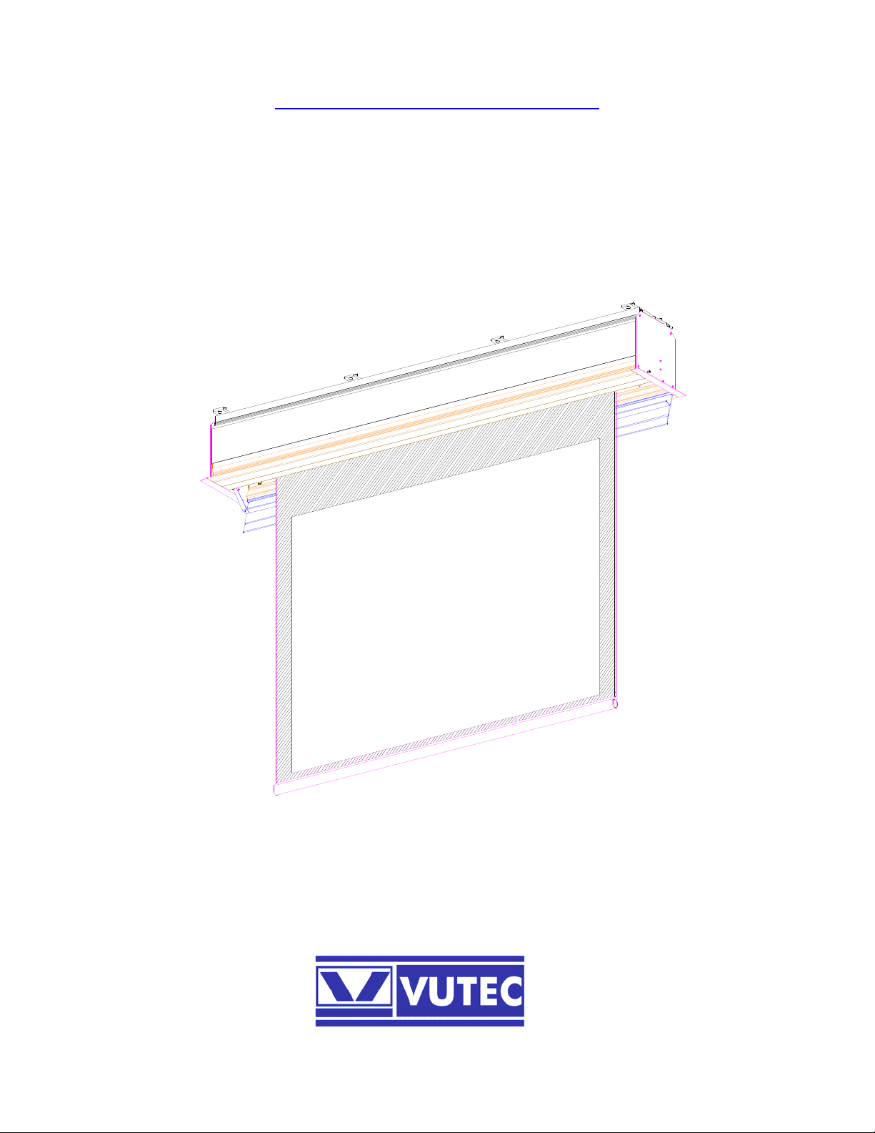
Installation Instructions
Vision XTC2
FLUSH CEILING MOUNT SCREEN
MOTORIZED DOOR
07/02/08 Rev. A
VIDEO PROJECTION SCREENS
INSTL-XTC2_MAIN_A
Page 2
IMPORTANT SAFETY INSTRUCTIONS
Basic safety precautions should always be followed; including the following:
♠ Read and understand all instructions before proceeding with the installation and operations.
♠ Be certain that the supporting structure is sound and capable of carrying the weight as required.
♠ Seek qualified electricians to perform electrical requirements.
♠ Obtain proper lifting mechanism to raise and hold the unit steady for installation.
♠ Plan ahead so the installation can go smoothly and efficiently.
IMPORTANT WARNINGS AND CAUTIONS!
WARNING: A WARNING ALERTS THE POSSIBILITY OF SERIOUS INJURY OR DEATH IF THE INSTRUCTIONS ARE NOT
FOLLOWED.
CAUTION: A CAUTION ALERTS THE POSSIBILITY OF DAMAGE OR DESTRUCTION OF EQUIPMENT IF THE
INSTRUCTIONS ARE NOT FOLLOWED.
WARNING: FAILURE TO READ, THOROUGHLY UNDERSTAND, AND FOLLOW ALL INSTRUCTIONS CAN RESULT IN
SERIOUS PERSONAL INJURY, DAMAGE TO EQUIPMENT, OR VOIDING OF FACTORY WARRANTY! IT IS THE
INSTALLER’S RESPONSIBILITY TO MAKE SURE ALL COMPONENTS ARE PROPERLY ASSEMBLED AND
INSTALLED USING THE INSTRUCTIONS PROVIDED.
WARNING: FAILURE TO INSTALL ELECTRICAL REQUIREMENTS ACCORDING TO NATIONAL/LOCAL ELECTRICAL CODES
AND REGULATIONS MAY CAUSE PREMATURE FAILURE, FIRE HAZARD, ELECTRICAL SHOCK, UNSAFE
PRACTICE AND REVOCATION OF USE.
DISCLAIMER
Vutec Corporation intends to make this manual accurate and complete. However, Vutec makes no claim that the
information contained herein covers all details, conditions or variations, nor does it provide for every possible contingency
in connection with the installation for use of this product. The information contained in this document is subject to change
without notice. Vutec makes no representation of warranty, expressed or implied, regarding the information contained
herein. Vutec assumes no responsibility for accuracy, completeness or sufficiency of the information contained in this
document.
PRE- INSTALLATION
1) Carefully cut and remove packing materials.
2) Carefully unpack and inspect the unit for sign of damages.
3) Be sure to recheck and measure all pertinent dimensions before installation.
4) Most basic tools are required for installation.
SAVE THESE INSTRUCTIONS
1
Page 3
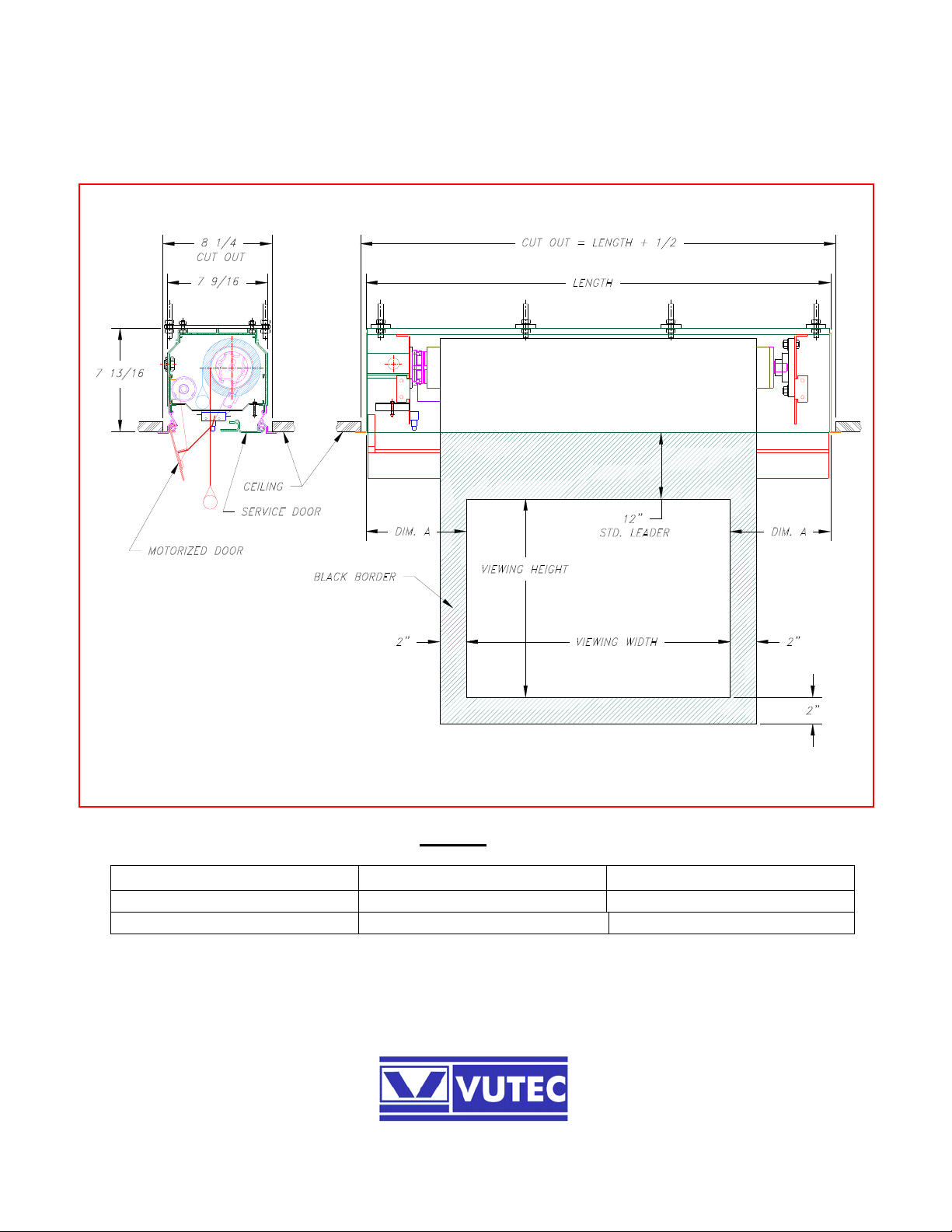
FLUSH CEILING MOUNT WITH MOTORIZED DOOR
SELF-SUPPORTED (shown) and TAB-TENSIONED screens
VISION XTC2
Figure 1
SCREEN TYPE LENGTH DIM. A
SELF-SUPPORTED VIEWING WIDTH + 15 1/2 7 3/4
TAB-TENSIONED VIEWING WIDTH + 22 1/2 11 1/4
2
Page 4
HOUSING INSTALLATION
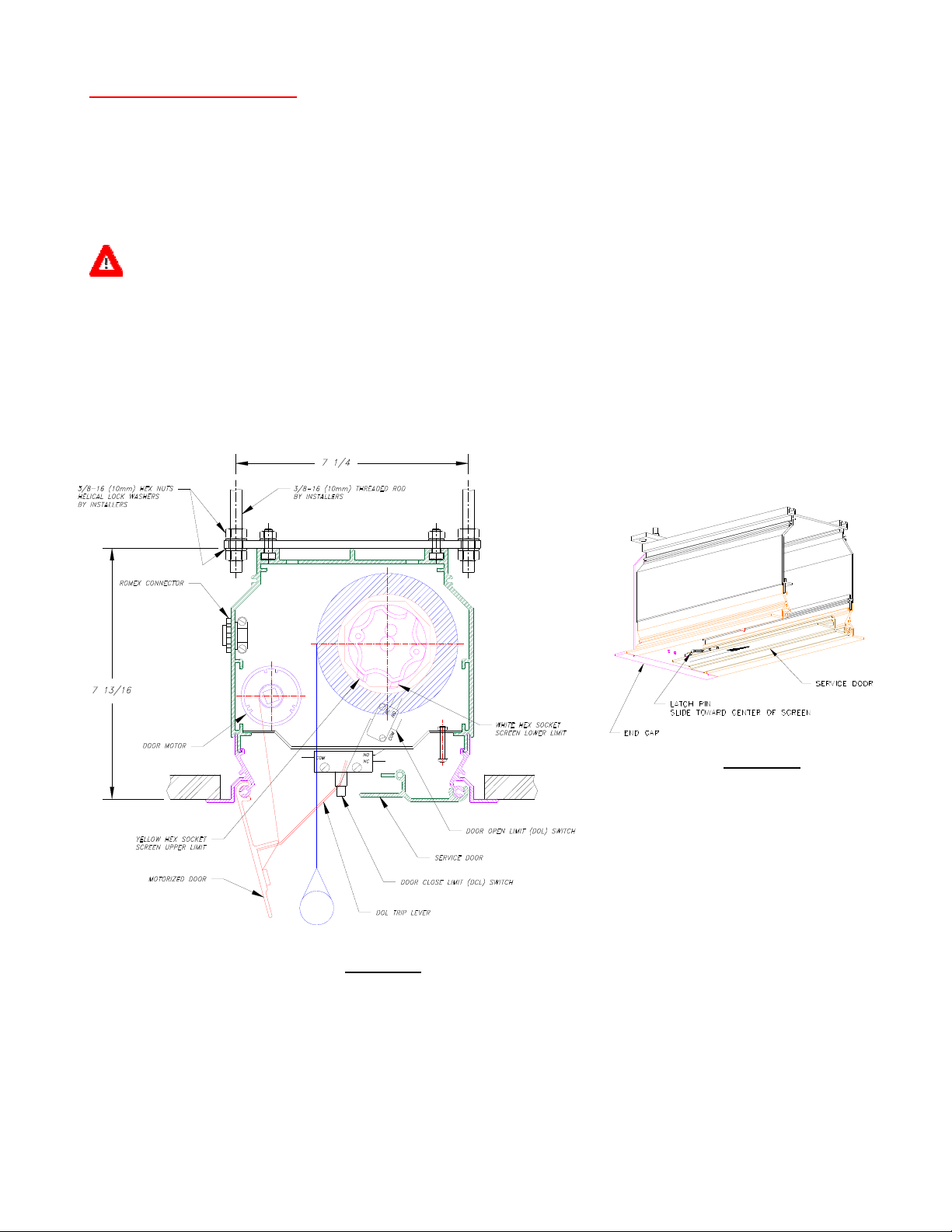
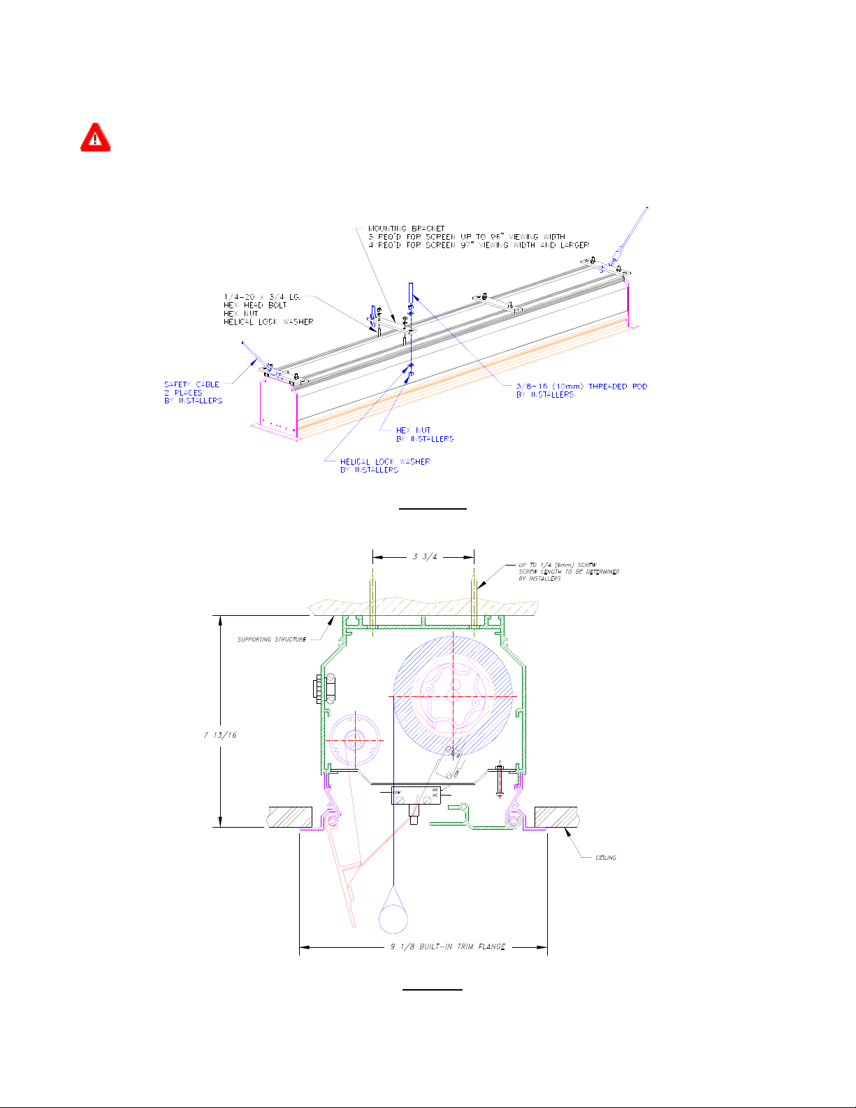
Vision XTC2 is designed for flush ceiling mount. As shown in Figure 2a, Option 1 is the preferred mounting
method which requires access space above the ceiling. The mounting brackets may be placed anywhere along
the housing length as desired. However, it is best to evenly space them for uniform weight distribution. It is
recommended the end mounting brackets should not be more than 4 inches from each end of housing.
The housing has a built-in trim flange around the bottom. Ceiling tiles or drywall may be placed on top of this
flange to provide a finished appearance.
WARNING: SUPPORTING STRUCTURE MUST BE CAPABLE OF CARRYING 4 TIMES THE UNIT WEIGHT. CHECK WEIGHT
Threaded rods of 3/8 (10mm) diameter, hex nuts and helical lock washers are to be provided by installers.
After securing the housing in the ceiling check that the housing is level and plumb. Make adjustments as
necessary then tighten the hex nuts.
It is recommended that safety cables be added to the housing for additional safety concern. The cables may be
looped and tied to end mounting brackets between the housing and bracket (Figure 2c).
DATA AT THE END OF THIS DOCUMENT.
Figure 2b
Some Parts Removed
For Illustration
Figure 2a
Option 1 - Suspended Mounting
An alternate mounting method is available as shown in Figure 3. This mounting option must be requested in
advance at the time of order placement for the mounting holes to be drilled.
It is the installer responsibility to supply proper mounting hardware for option 2 mounting.
Option 2 mounting requires the screen roller assembly to be removed to gain access for the mounting screws
along the middle section of the housing.
3
Page 5
If the unit was shipped complete with the screen roller assembly installed; proceed to SCREEN ROLLER
ASSEMBLY REMOVAL Section for instructions.
CAUTION: BE SURE TO PLACE THE CONNECTING WIRES INSIDE BEFORE PROCEEDING WITH THE HOUSING
Install the housing once the screen roller assembly is removed. Be sure the housing is level and plumb.
INSTALLATION.
Figure 2c
Option 1 - Suspended Mounting
Figure 3
Option 2 – Blind Pocket Mounting
4
Page 6
ELECTRICAL CONNECTIONS
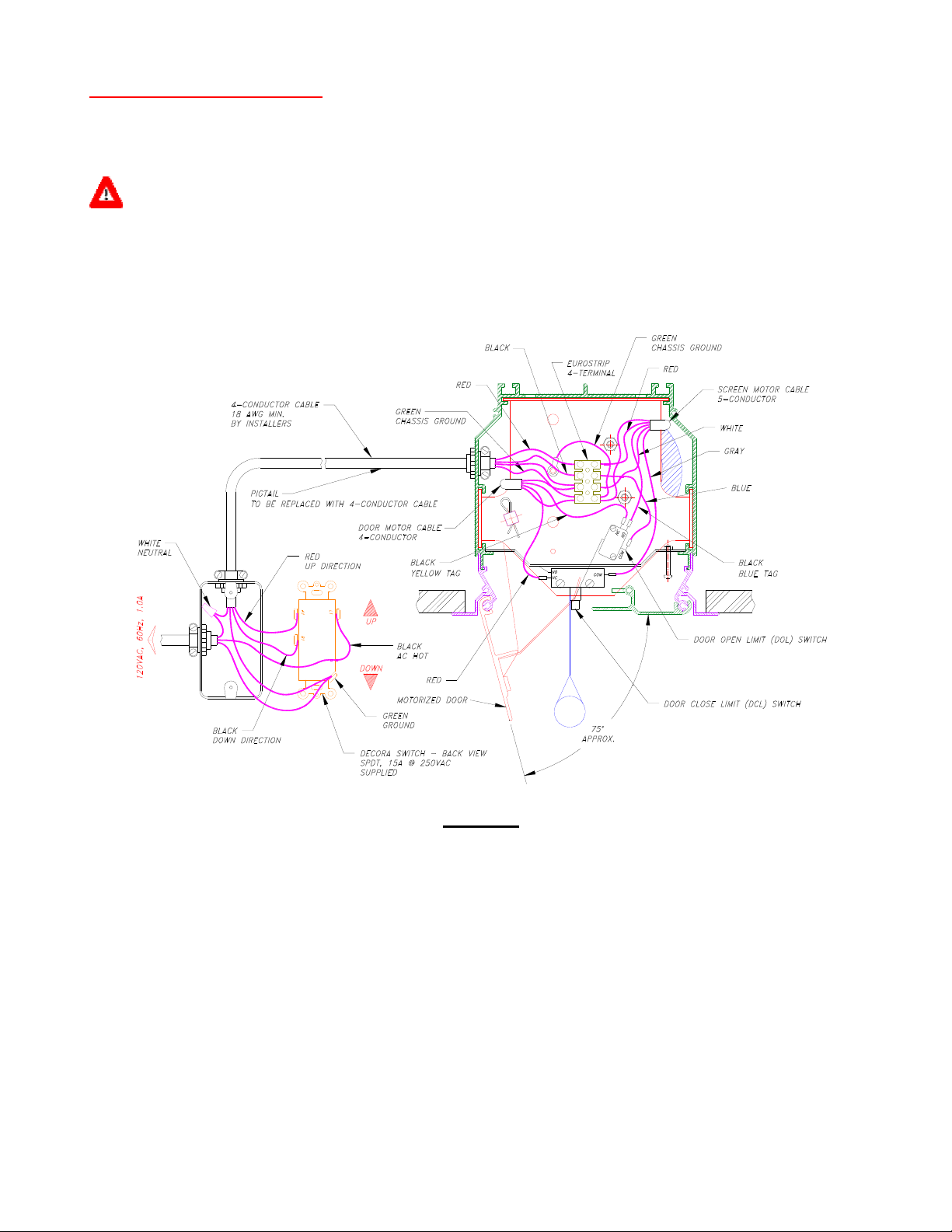
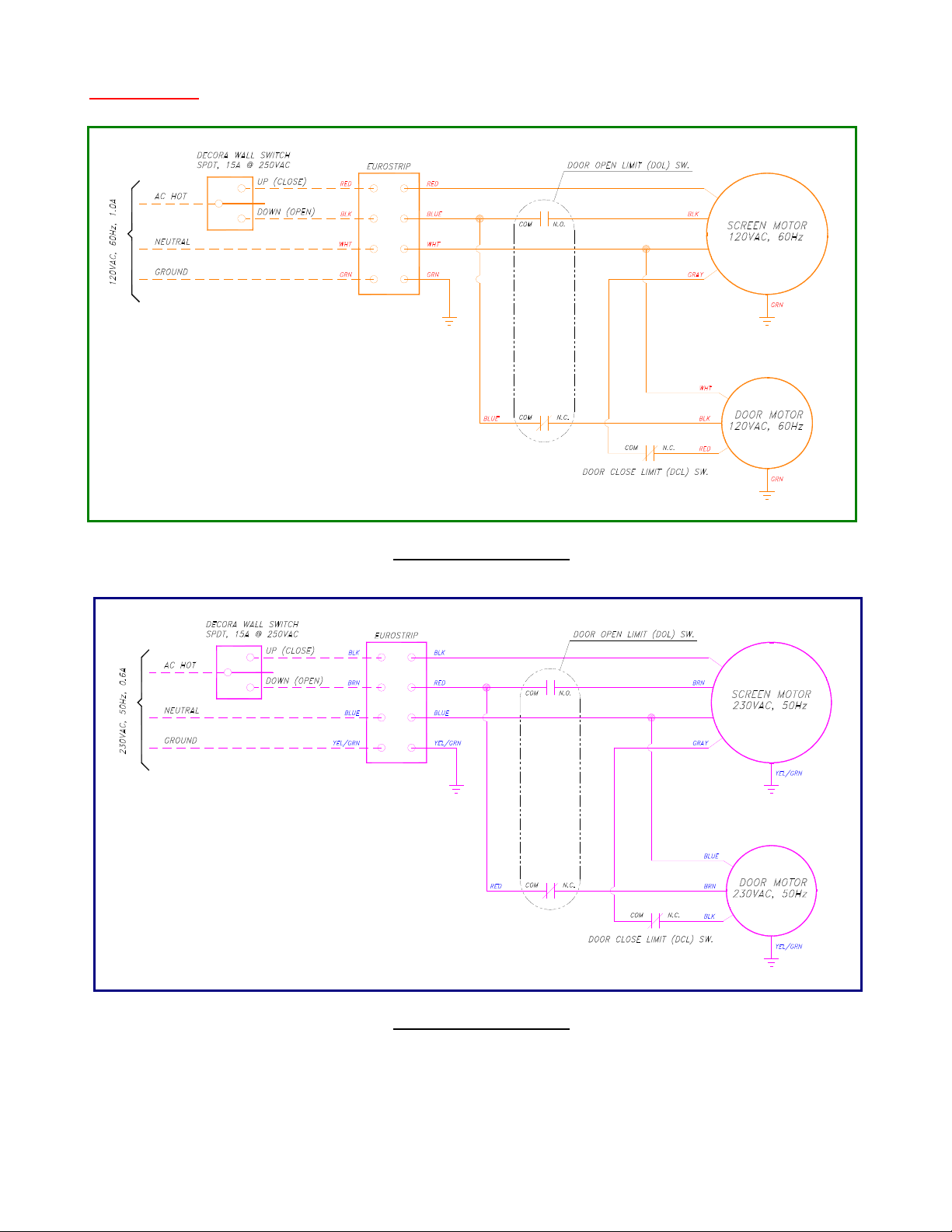
If the unit was shipped complete with the motor and roller assembly inside; then there is a 4-wire pigtail
provided for a quick hook-up to operate the screen. Refer to Figure 4a or Figure 4b, make the required
connections to the switch for operations.
WARNING: THE INITIAL HOOK-UP AND CALIBRATION PROCEDURES ARE INTENDED TO BE PERFORMED BY A
Press the down direction on the switch to open the motorized door. Stop when the screen begins to descend.
On each end of the service door; slide the latch pin (Figure 2b) toward the center to open the door.
Turn off power and disconnect the switch from the pigtail.
QUALIFIED SERVICE MAN.
Figure 4a
Electrical Connections 120 VAC
Remove the electrical cover to gain access to the electrical compartment. Simply push up or using a screwdriver
and make a light hit upward on the cover to open (Figure 5a).
Pull down the Eurostrip to replace the pigtail with 4-conductor cable. The cable should go to location where the
wall switch is to be located.
Make connections to the switch as shown in Figure 4. Perform quick test by sending the screen down half way
and stop. Send the screen back up without closing the trap door then stop.
Push the Eurostrip back up in the electrical compartment and reinstall the electrical cover. Refer to Figures 5a
and 5b, maintain clearance for the DOL switch while pulling down on the cover. Note the cover is lightly force
fit inside the housing.
Close the service door and reinstall the latch pin on each end.
NOTE: FOR 230VAC INSTALLATION, REFER TO FIGURE 4b.
5
Page 7
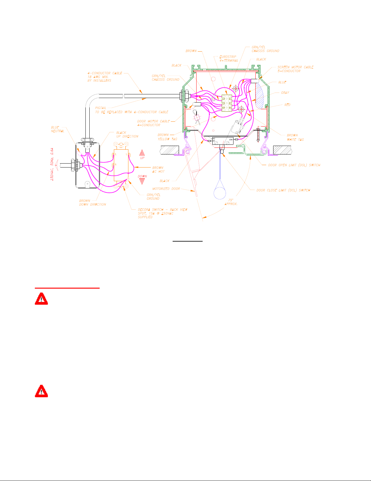
Figure 4b
Electrical Connections 230 VAC
The screen may also be operated by optional IR/RF remote control, optional 12VDC trigger relay, optional Low
Voltage control or optional Home Automation control by AMX, Crestron, etc. Consult Vutec for further details.
FIRST OPERATION
CAUTION: THE FIRST CYCLE DOWN AND UP OF THE SCREEN MUST BE PERFORMED UNDER CONTROL OF AN
ATTENDANT. THE MOTOR LIMIT SWITCHES MIGHT BE DISENGAGED DURING SHIPPING WHICH WILL NOT
STOP THE SCREEN AUTOMATICALLY AND MAY CAUSE DAMAGE TO THE SCREEN IF IT IS ALLOWED TO
COME DOWN BELOW LEADER REQUIREMENT.
Verify the leader requirement for the installation. Send the screen down and expect it to stop at the leader
requirement. Stop if the screen appears to go up on the front side of the roller.
If the screen stopped at the leader requirement; send it back up to close the motorized door which in turn trips
the DCL switch to stop the door motor.
If the screen went below the leader requirement; stop! Send it back up half way, stop! Proceed to LOWER
LIMIT ADJUSTMENT Section for instructions.
CAUTION: THE MOTOR IS EQUIPPED WITH THERMAL OVERLOAD PROTECTION DEVICE. OPERATING THE SCREEN
WITHOUT ALLOWING SUFFICIENT OFF TIME COULD RESULT IN THERMAL OVERLOAD SHUT DOWN. IF
THIS OCCURS, SIMPLY ALLOW THE MOTOR TO COOL DOWN (APPROXIMATELY 15 MINUTES) BEFORE
RESUMING NORMAL OPERATION.
6
Page 8
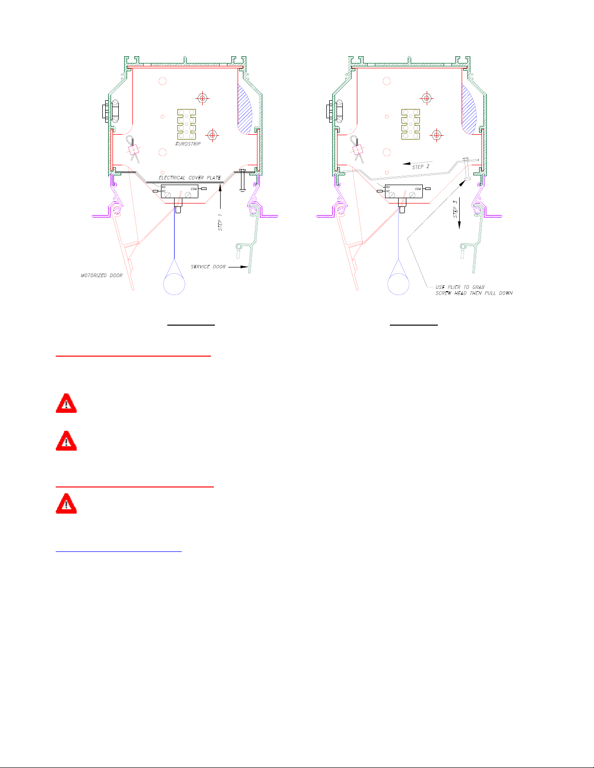
Figure 5a Figure 5b
UPPER LIMIT ADJUSTMENT
The upper limit for the screen is approximately 2 inches inside the housing. Do not change the screen upper
limit unless absolutely necessary.
CAUTION: BE SURE THE MOTOR IS SHUT OFF WHEN THE MOTORIZED DOOR IS CLOSED. IF THE MOTOR STILL
RUNNING (HUMMING) THEN THE DCL SWITCH MUST BE ADJUSTED TO SHUT OFF THE MOTOR.
WARNING: FAILURE TO CHECK AND CORRECT THE MOTOR SHUT OFF CONDITION AFTER THE MOTORIZED DOOR IS
CLOSED MAY CAUSE SEVERE DAMAGE TO THE MOTOR AND VOID THE WARRANTY.
LOWER LIMIT ADJUSTMENT
WARNING: UNLESS OTHERWISE SPECIFIED AND ORDERED, STANDARD LEADER DROP IS 12 INCHES MAXIMUM.
EXCEEDING THE MAXIMUM MAY CAUSE THE SCREEN TO FALL OFF THE ROLLER AND VOID THE
WARRANTY.
HEX SOCKET LIMIT SWITCH
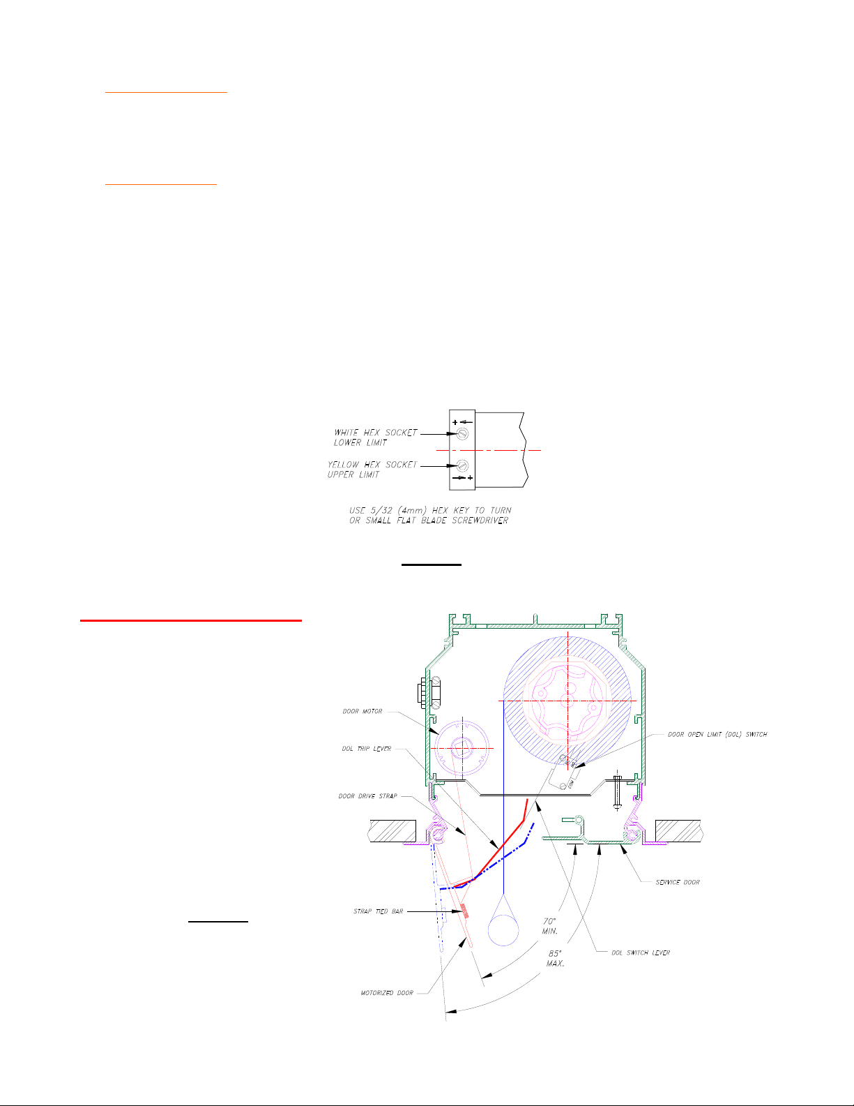
Key features of the hex socket (Figures 2a and 6) limit switch:
⇒ Each full turn (360 degrees) of the hex socket cause the screen to travel approximately 3/4 inch.
⇒ Follow the label affixed to the electrical cover plate for turning of the hex sockets.
⇒ As the hex socket is turning, the screen will move only in the direction of increasing travel.
Hint: Going down direction (lower limit) will see the screen move as more down being adjusted but not
the opposite.
7
Page 9
MORE SCREEN DROP
Send the screen down to the lower limit and it should stop automatically. Leave the control switch on.
Turn the White hex socket in the + direction (see label on electrical cover plate) to make the screen come down
more. Stop turning when the screen reaches the desired lower limit.
LESS SCREEN DROP
Send the screen down to the lower limit and it should stop automatically. Leave the control switch on.
Determine the number of turns required to stop the screen above the desired lower limit.
Turn the White hex socket in the - direction the number of turns that has been determined to make it stop above
the desired lower limit.
Send the screen up half way and stop. Send it down and expect it to stop above the desired lower limit.
Repeat the steps above until the screen has stopped above the desired lower limit.
When the screen stops above the desired lower limit; proceed to
to the desired lower limit.
MORE SCREEN DROP part to lower the screen
Figure 6
Limit Switch Sockets
DOOR MOTOR OPERATIONS
The lower limit of the door motor is
set and coupled to the door at its
maximum open angle of 85 degrees.
The door may be set to stop between
70 to 85 degrees by lightly bends the
DOL switch lever more or less. The
DOL trip lever contacts the switch
lever in the open and stops the door
accordingly.
Do not adjust the door motor limit
switches.
Figure 7
Motorized Door Components
8
Page 10
SCHEMATIC
120 VAC Installations
230 VAC Installations
9
Page 11
TROUBLESHOOTING
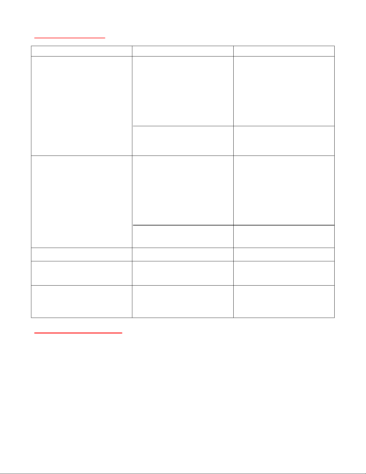
SYMPTOM CAUSE SOLUTION
Door remains closed and screen will not
come down.
Motor does not hum.
Motor hums.
Screen will not go up.
Motor does not hum.
Motor hums.
a- Check breaker fuse.
b- Check wall switch.
c- Push button limit switches might be
tripped.
d- Thermal overload tripped.
e- Defective motor or wall switch.
f- Temporary binding.
g- Capacitor burned out.
a- Check breaker fuse.
b- Check wall switch.
c- Push button limit switches might be
tripped.
d- Thermal overload tripped.
e- Defective motor or wall switch.
f- Temporary binding.
g- Capacitor burned out.
a- Replace blown fuse.
b- Check wall switch connections.
Bypassing wall switch as a test.
c- Manually open trap door. See Electrical
to reset push button limit switch. Reset
Yellow button for lower limit.
d- Let motor cool down for 15 minutes.
e- Replace motor or wall switch.
f- Manually open trap door check for
binding.
g- Replace motor.
a- Replace blown fuse.
b- Check wall switch connections.
Bypassing wall switch as a test.
c- See Electrical to reset push button limit
switch. Reset White button for upper
limit.
d- Let motor cool down for 15 minutes.
e- Replace motor or wall switch.
f- Check for binding of roller assembly.
g- Replace motor.
Coasting. a- Defective brake. a- Replace motor.
Trap door closed and motor hums.
Trap door not quite closed but motor stop.
Noisy operations. a- Cyclic noise (squeaky) pattern.
a- Check Door Close Limit (DCL) switch a- Adjust DCL switch by moving it up or
down.
a- Lubricate roller shaft and bearing at Idler
b- Gear noise
bracket with typical oil.
b- Replace motor.
ACCESSORIES INCLUDED
1 SPDT DECORA SWITCH
1 SWITCH COVER PLATE
4 MOUNTING BRACKET
9 1/4-20 X 1” LONG HEX HEAD BOLT
9 HELICAL LOCK WASHER FOR 1/4 BOLT
9 1/4-20 HEX NUT
10
 Loading...