

Page 1
Installation Instructions
HOME THEATER SERIES
VISION XMV
DUAL-ASPECT MASKING SCREEN
11/20/99
XMV-INSTL_A.doc
VIDEO PROJECTION SCREENS
Page 2
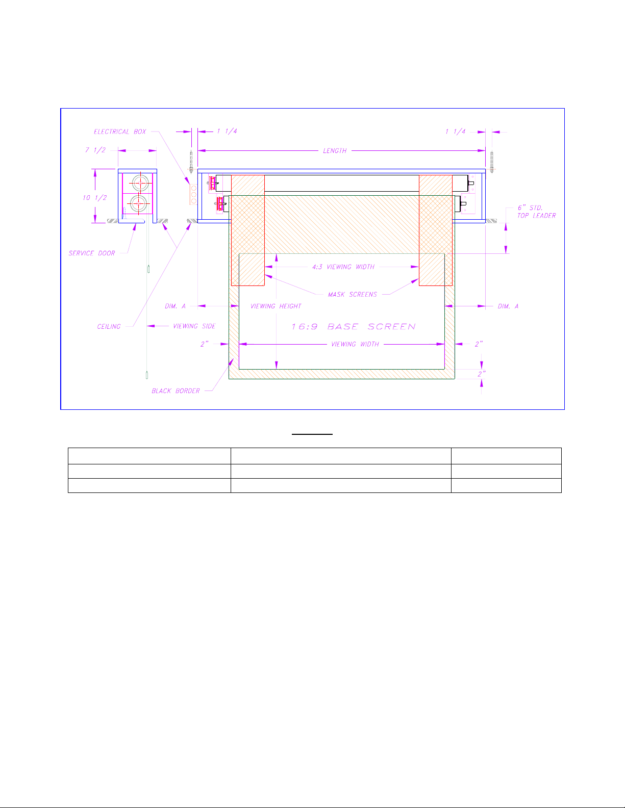
STANDARD (shown) and TAB-TENSIONED screens
DUAL-ASPECT MASKING SCREEN
Figure 1
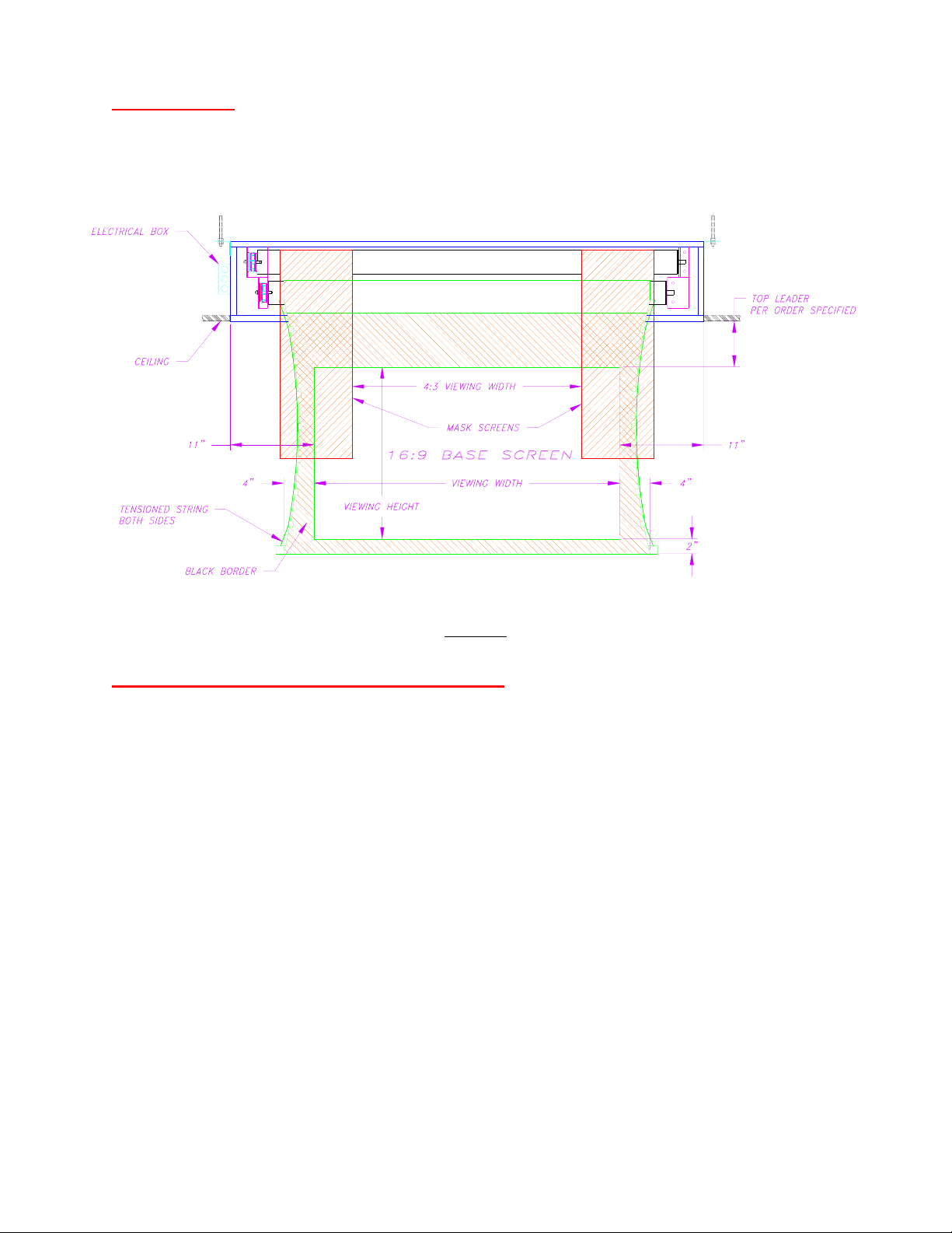
SCREEN TYPE LENGTH DIM. A
STANDARD BASE SCREEN VIEWING WIDTH + 16” 8”
TAB-TENSIONED (Figure 3) BASE SCREEN VIEWING WIDTH + 22” 11”
1
Page 3
INSTALLATION
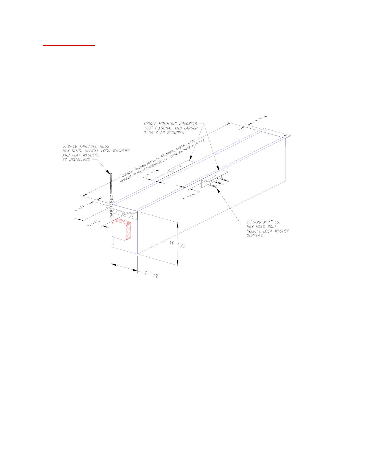
The VISION XMV screen is designed for flush ceiling mount. Referring to Figure 2, installation requires
3/8 inch diameter threaded rods for hanging (not supplied). Two threaded rods are required for each end
bracket. Additionally, a threaded rod is needed for each middle bracket as required.
Referring to the table in this manual, determine the weight of the screen to be hung. Inspect the
supporting structure of the area where the screen will be hung. Be sure the supporting structure is capable
of carrying a minimum of four times the weight of the screen. It is recommended that safety cables be
added to the screen housing for additional security.
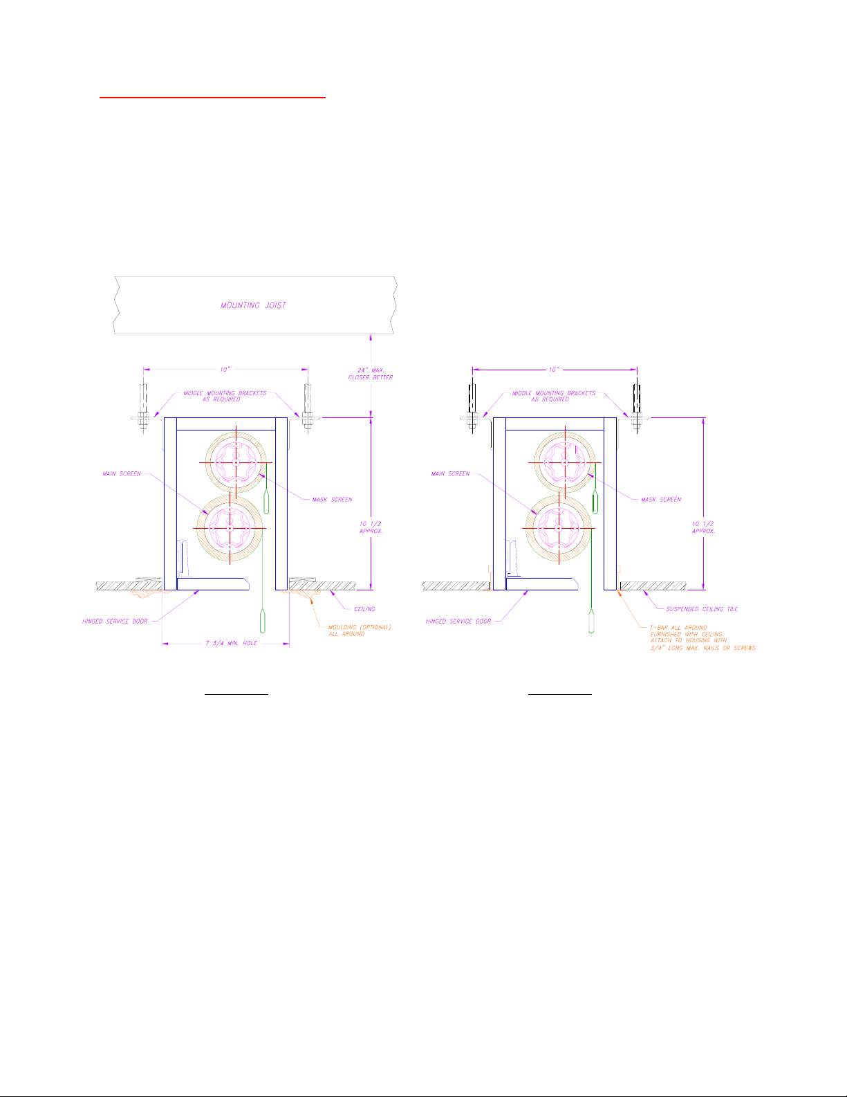
Referring to Figures 2a and 2b, the length of the threaded rod for suspended mount should be as short as
possible for stability. If this is not so, additions and/or modifications to the mounting structures may be
required.
Depending on the hole size, the mounting brackets may be removed for fitting of the housing thru the
hole then reinstall them from above. Be sure to use helical lock washers (not supplied) when tightening
the threaded rods to the mounting brackets and the mounting structures.
Bottom finish may be done by fill in the gaps between the hole and the housing or apply moulding to
cover the gaps as desired (Figure 2a). For ceiling tile installation, add T-bars to the housing to support the
tiles and a finish look (Figure 2b).
The VISION XMV screen comes with a hinged service door to access the screen rollers. Be sure the
finished ceiling does not interfere with the opening of the door.
Figure 2
2
Page 4
ELECTRICAL CONNECTIONS
1 - Be certain the power is OFF before making electrical connections. All wiring and connections
are required to comply with National and/or Local electrical codes.
2 - The VISION XMV screen operates on 120VAC, 60Hz power. Control of the screen requires two
SPDT wall switches (supplied) with center OFF position. One switch operates the main screen
and the other switch operates the mask screen. Optionally, the screen can be operated by RF or
IR remote controls, or integrated to an automation system. Please consult the dealers for details.
Figure 2a Figure 2b
3 - A wiring diagram is provided at the end of this manual. Wiring must be of 18 AWG minimums.
4 - Run two 4-conductor cables from the screen’s junction box to the switches’ location.
5 - Make connections per the wiring diagram. Be sure power if OFF when connecting power lines.
6 - Turn ON the power; the screen is ready for operations.
3
Page 5
OPERATIONS
Send the main screen DOWN or UP by toggling the switch for that screen. Same operations are for the
mask screen.
CHANGING THE UPPER AND LOWER LIMITS
Referring to Figure 3, the lower limit of the tab-tensioned screen has been set at the factory to specific
ordered. It can not be made lower than the pre-set lower limit!
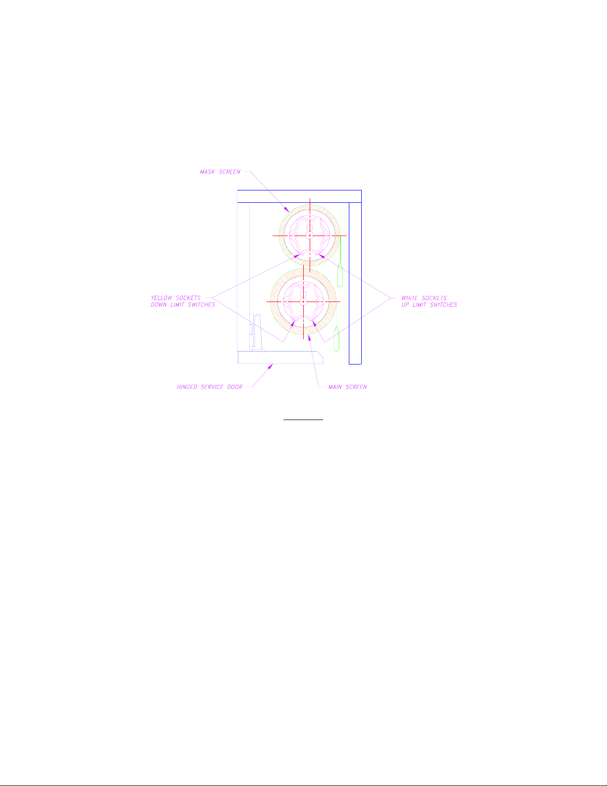
Referring to Figure 4, each screen motor has two built-in limit switches. The yellow socket sets the lower
limit and the white socket sets the upper limit. Open the service door to access the motor limit switches.
Use 5/32 hex key or 1/8 wide flat blade screwdriver for turning.
Each full turn causes the screen to travel 1 inch approximately.
Counter-clockwise turning is same as tightening a screw into the ceiling.
Figure 3
INCREASING THE LOWER LIMIT
1 - STOP! The following steps are not possible for tab-tensioned screen.
2 - Send the screen down to its lower limit. Leave the down switch on.
3 - Turn the yellow socket clockwise; the screen will advance downward as each full turn is made. Stop
at the desired position.
4 - Send the screen back up few inches then sending it back down to check the new lower limit.
5 - Repeat the steps if the lower limit is still higher. See Decreasing The Lower Limit if the lower limit
is lower than the desired position.
4
Page 6
DECREASING THE LOWER LIMIT
1 - Send the screen down to its lower limit.
2 - Determine the number of full turn to set the lower limit above the desired position. Use the example
and add at least 4 full turns to the desired travel.
Example: To raise the lower limit up 6 inches from current stopping point.
Make 10 full turns to be sure the next lower limit will be above the desired position.
Figure 4
3 - Turn the yellow socket counter-clockwise the number of turns determined in step 2. There is no
screen movement while doing so in this step.
4 - Send the screen up past the desired lower limit and stop. Send the screen down and it should stop
above the desired lower limit as expected.
5 - See Increasing The Lower Limit to set the desired lower limit.
INCREASING THE UPPER LIMIT
1 - Send the screen up to its upper limit. Leave the up switch on
2 - Turn the white socket clockwise; the screen will advance upward as each full turn is made. Stop at
the desire position.
3 - Repeat the steps as necessary.
DECREASING THE UPPER LIMIT
1 - Send the screen up to its upper limit.
2 - Determine the number of full turn to set the upper limit below the desired position. Use the example
and add at least 4 full turns to the desired travel.
Example: To lower the upper limit 6 inches from current stopping point.
Make 10 full turns to be sure the next upper limit will be below the desired position.
5
Page 7

3 - Turn the white socket counter-clockwise the number of turns determined in step 2. There is no
screen movement while doing so in this step.
4 - Send the screen down past the desired upper limit and stop. Send the screen up and it should stop
below the desired upper limit as expected.
5 - See Increasing The Upper Limit to set the desired upper limit.
ACCESSORIES INCLUDED
2 DECORATOR SPDT CENTER OFF SWITCH
6
 Loading...