

Page 1
Installation Instructions
HOME THEATER SERIES
VISION XL & XL1
WALL OR CEILING MOUNT SCREENS
VIDEO PROJECTION SCREENS
01/24/00
INSTL-XS_A.doc
Page 2
WALL or CEILING MOUNTING
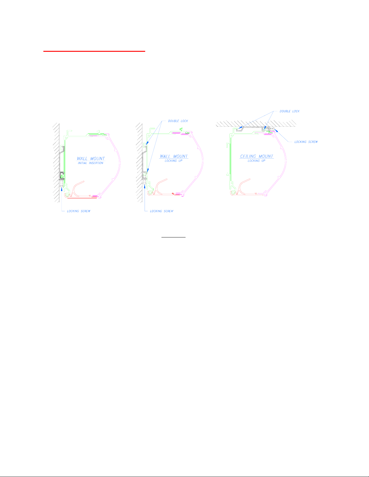
The VISION XL or XL1 screen designed to be mounted to the wall or the ceiling as shown in
Figure 1. Each screen unit comes with two mounting brackets and mounting screws. For optimum weight
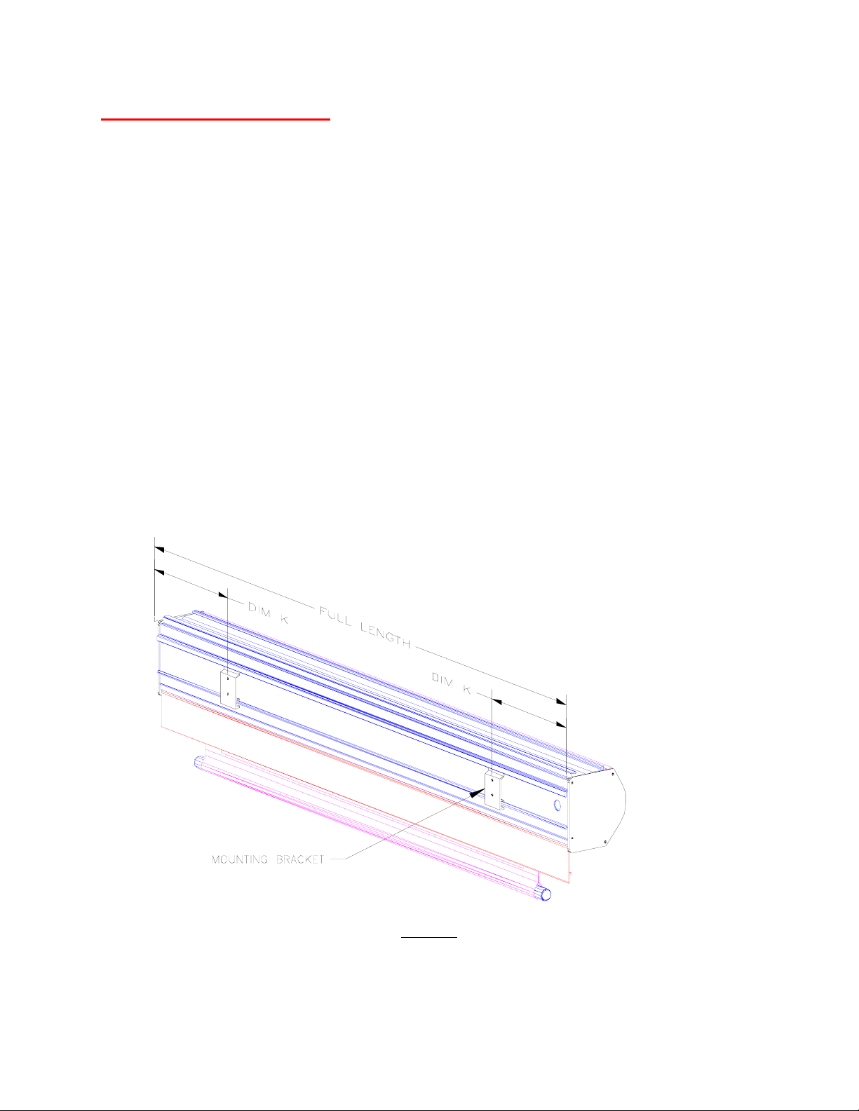
distribution, the mounting brackets should be located a 1/4 of the housing length from each ends of the
housing (see Figure 2). Where possible, the mounting screws should be attached to rigid structural
members. If this is not possible, suitable wall anchors or other mounting methods must be considered.
Vision XL1 shown
The following information is important when deciding the mounting location for the screen.
− The screen is centered in the housing.
− Standard screen has 12 inches maximum top leader.
− Tab-Tensioned screen has the top leader set to specified order.
The following procedure applies to both wall and ceiling mounting types.
1. Determine the mounting location on the wall or on the ceiling. Be sure the mounting area is flat
and free of object protruding more than 1/4 inch.
2. If possible, run a chalk line to check the level for the mounting brackets.
3. Install the mounting brackets to the wall or the ceiling. Dim K should be 1/6 to 1/8 of the full
housing length in from each end (see Figure 2). Tighten all screws.
4. Attach a locking screw to each mounting bracket. Do not allow the locking screw to go through.
5. Slightly tip the screen housing and guide it into the brackets. If this is a ceiling installation, move
the screen housing away from the locking screws so the screen top mounting channel completely
rest on the brackets. Center the screen by sliding it side to side.
Figure 1
6. Tighten the locking screw of each bracket to double lock the screen housing to the brackets.
1
Page 3
ELECTRICAL CONNECTIONS
The VISION XL or XL1 screen comes with a trap door to completely hide and protect the screen when
not in use. The trap door trips the Door Close Limit Switch and shuts off the screen motor when the
screen is fully retracted into the housing.
1. Be certain the power is OFF before making any electrical connections. All wiring and connections
are required to comply with National and/or Local electrical codes.
2. The VISION XL or XL1 screen operates on 120VAC, 60Hz power. Control of the screen is usually
by a SPDT toggle switch with center ‘OFF’ position. Optionally, the screen can also be operated by
an IR (Infrared), a RF (Radio Frequency) remote control, or a relay-triggering device. Please consult
the dealer for details.
3. A wiring diagram is provided at the end of this manual. All wiring should be made using minimum
18-gauge wire.
For installation equipped with 220VAC motor, the wires for the motor are as follow:
120VAC motor 220VAC motor Description
Green Yellow/Green Ground
White Blue Neutral
Red Black Screen up direction
Black Brown Screen down direction
Full Length (Standard) = Viewing Width + 15 1/2
Full Length (Tab-tensioned) = Viewing Width + 22 1/2
Figure 2
Back view of screen housing
2
 Loading...