

Page 1
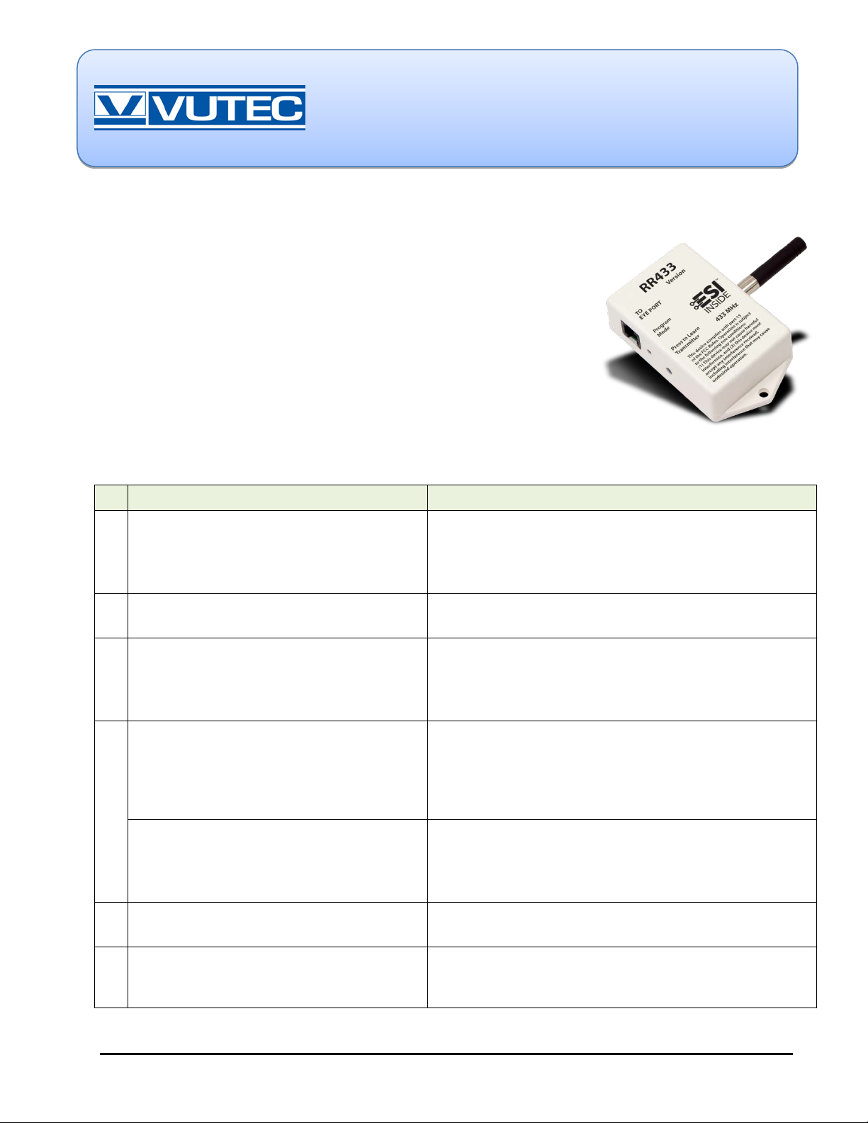
The RR433 is a 433 MHz Radio Receiver module with plastic enclosure and
extending the effective range of a 433 MHz RF system.
INSTRUCTIONS
Introduction
RF antenna. The RR433 can pair with up to five transmitters. Each RF
transmitter outputs a unique security code prior to sending an action
command. The RR433 must “learn” each unique security code prior to use.
The RR433 listens to commands from a number of sources including: RF
keypads, RF transmitters, and the RF Transmitter Module (RFTM 433)
which sends commands from devices such as Sun and Wind sensors.
The RR433 is designed for 433 MHz RF control of an RP motor control
system. One RR433, connected to an RP bus, can control up to 60 motors.
If needed, multiple RR433 units can be installed on the RP bus, thereby
Pairing Instructions
VUTEC Corporation
11711 W.Sample Rd.
Coral Springs, FL 33065 U.S.A.
www.vutec.com
Tel: (954) 545-900
# STEPS NOTES
Ensure the RR433 has power.
1
If the Program Mode LED is on solid red,
2
skip to Step 4.
Press and release the “Press to Learn
3
Transmitter” button.
NOTE: The Program Mode LED turns on solid red
for approximately 8 seconds.
While the Program Mode LED is on solid
4
red, press and release the STOP button
on an ESI 433 MHz RF transmitter.
NOTE: The Program Mode LED will turn off, to
indicate that a valid pairing command was
received, or that the 8 second “learni ng” window
has expired.
— Valid modular connection s are to an E YE or BUS port on the RP bus.
— Test for power: disconnect the m odul ar conn ect i on and reconnect.
The Program Mode LED blinks red on power up (se e the Specifications
section below for number of blinks).
— If the RR433 has no paired transmitters, t he Program Mode LED
turns on solid red until power is removed, or a t ransmi t ter is paired.
— If the RR433 has one or more paired transmitt ers, t he Program Mode
LED will be off at the beginni ng of this S t ep.
— If the LED does not illum i nat e, t he RR433 has alread y “learned” five
transmitters, and all 5 mem ory slots are f ull .
— Another button can be pressed on a transmitter, and the “learn”
process will still work. However, undesired motor action may happen
immediately after t he “learn” proc ess.
— IMPORTANT: the key fob has special pairing instructions. See the
document: T1 RFV2 433 Appl i cati o n Notes.
— Subsequent presses of any butt on on a “pai red” t ransmitter (except
SHIFT on the T24 transmitter) caus es t he P rogram M ode LED to blink.
— If no valid pairing command was received wit hi n 8 se conds, the
Program Mode LED will turn off , blink on, and then turn off.
Repeat Steps 3 and 4 for additional
5
transmitters.
On the paired transmitter, press a button
6
to test that the transmitter is working
correctly.
October 2012, rev 1 © 2013 VUTEC Corporation Page 1 of 5
— Up to five total transmitters may be paired with the RR433.
— The Program Mode LED blinks on, then turns off, indicating the
transmitted signal was recei ved and se nt.
Page 2
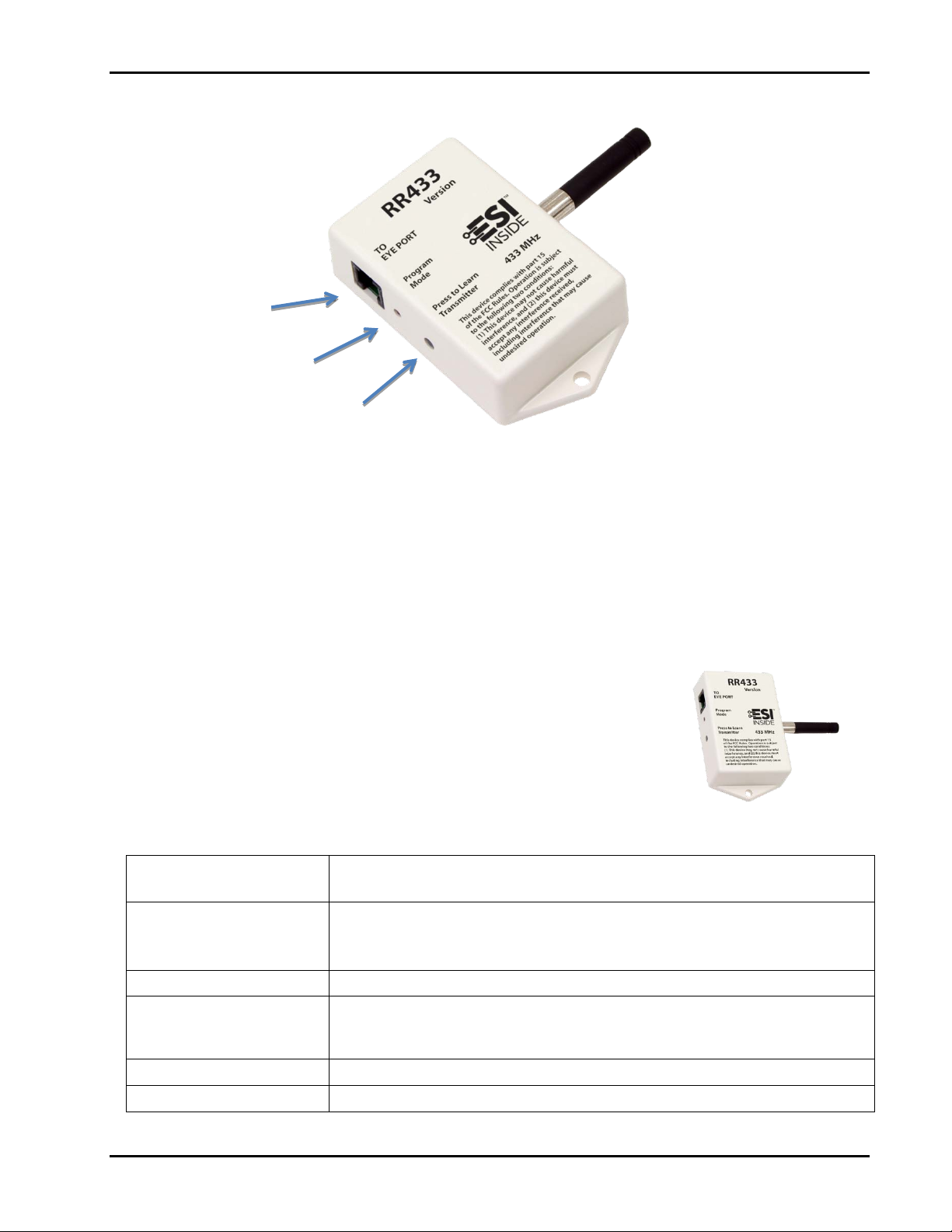
Horizontal Orientation
Modular Connection
Program Mode LED
Press to Learn Transmitter
button
Reset to Fact ory Default
NOTE: The following sequence will clear all paired transmitter security codes from the RR433 memory.
1. While the Program Mode LED is off, press and hold the “Press to Learn Transmitter” button until the
Program Mode LED blinks on, then off, then stays on (takes approximately 6 seconds).
2. Release the “Press to Learn Transmitter” button.
3. The Program Mode LED will stay on indefinitely until the first transmitter is paired.
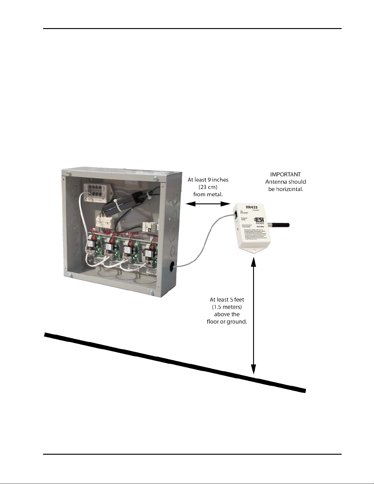
Antenna Orientation
• Mount the RR433 with the antenna pointing horizontally, parall el t o the floor or ground, to
maximize reception.
• Install in open area, outside of a metal enclosure, and at least 5 f eet (1.5 meters) above
the floor or ground.
• Ideally, the antenna should be at least 9 inches (23 cm) from any metal surface.
• Effective range is 50 feet (15 meters) unobstructed.
• See the Optimum RF Reception Guide for additional information about ant enna
placement and the range of RF transmitters.
Specifications
FACTORY DE FAULT
VERSION BLINKS
(at power up)
FREQUENCY
POWER
DIMENSIONS (with antenna)
PAIRING
No paired transmitters. All five memory slots are cleared.
Program Mode LED stays on solid until the first transmitter is paired.
version 2 = 2 red blinks
version 5 = 5 red blinks
version 5.1 = 5 short and 1 long, red blinks
433.92 MHz
Supplied by +5VDC from modular connection to EYE or BUS port on RP bus motor
control or ESI accessory.
Current Draw = 25mA
Length: 3.86 in. x Width: 3.83 in. x Height: 0.89 in. (98.1 mm x 97.4 mm x 22.8 mm)
Can pair with a maximum of five (5) transmitters.
www.vutec.com © 2013 VUTEC Corporation Page 2 of 5
Page 3

Glossary
RF Keypad
Learn
LED
Pairing
RF
RP bus
RR433
Specifications
RF Transmitter
RF Transmitter
Module
V2
An ESI distributed RF device that transmits at 433 MHz. For example, the K24ST RF
433.
The process used by the RR433 to “memorize” a transmitter’s unique security code.
Light Emitting Diode (the red “Program Mode” LED).
To join a transmitter to an RR433 Radio Receiver.
Radio Frequency.
Remotely Programmable. Motor controls developed by ESI with one-way
communication and connected by data cable to form a communication system called
the “bus.”
Radio Receiver 433 MHz. Must use the RR433 (V2 or later) with T1 RFV2 433 key fob.
For additional information, refer to the “Specifications and Installation Instructions” for
the RR433.
Any ESI distributed RF device that transmits at 433 MHz. For ex am ple, the T1 RFV2
433, RFTM 433, T6S Dual 433, and T24S Dual 433.
An ESI distributed RF device that transmits at 433 MHz and allows for wireless
installation of keypads and other accessories that are RF-enabled. For example, the
RFTM 433.
version 2
www.vutec.com © 2013 VUTEC Corporation Page 3 of 5
Page 4
Introduction
The range of RF transmitters is affected by many conditions, some of which are controllable. A few factors
that limit RF transmission include antenna orientation, radio receiver placement, intervening objects, and EMI
(electromagnetic interference). To obtain maximum reliability and reception range, see the guidelines listed
below for installing an RR433 module.
Antenna Orientation
The antenna orientation on the RR433 affects range and reliability.
• The RR433 module must be installed outside of a metal enclosure.
• To maximize reception range, mount the RR433 with the antenna pointing horizontally, parallel to the
floor or ground.
• Other orientations are possible, but reception range will be reduced.
Radio Receiver Placement
Optimum reception is obtained by installing the RR433 module in an open area.
www.vutec.com © 2013 VUTEC Corporation Page 4 of 5
Page 5
• Avoid multi-path reflections. Do not place the module near wall corners or large reflecting surfaces,
such as mirrors (the thin metal layer is a reflector), file cabinets, and so on.
• Mount the RR433 module on wood or drywall. On drywall, the module should be mounted halfway
between two studs.
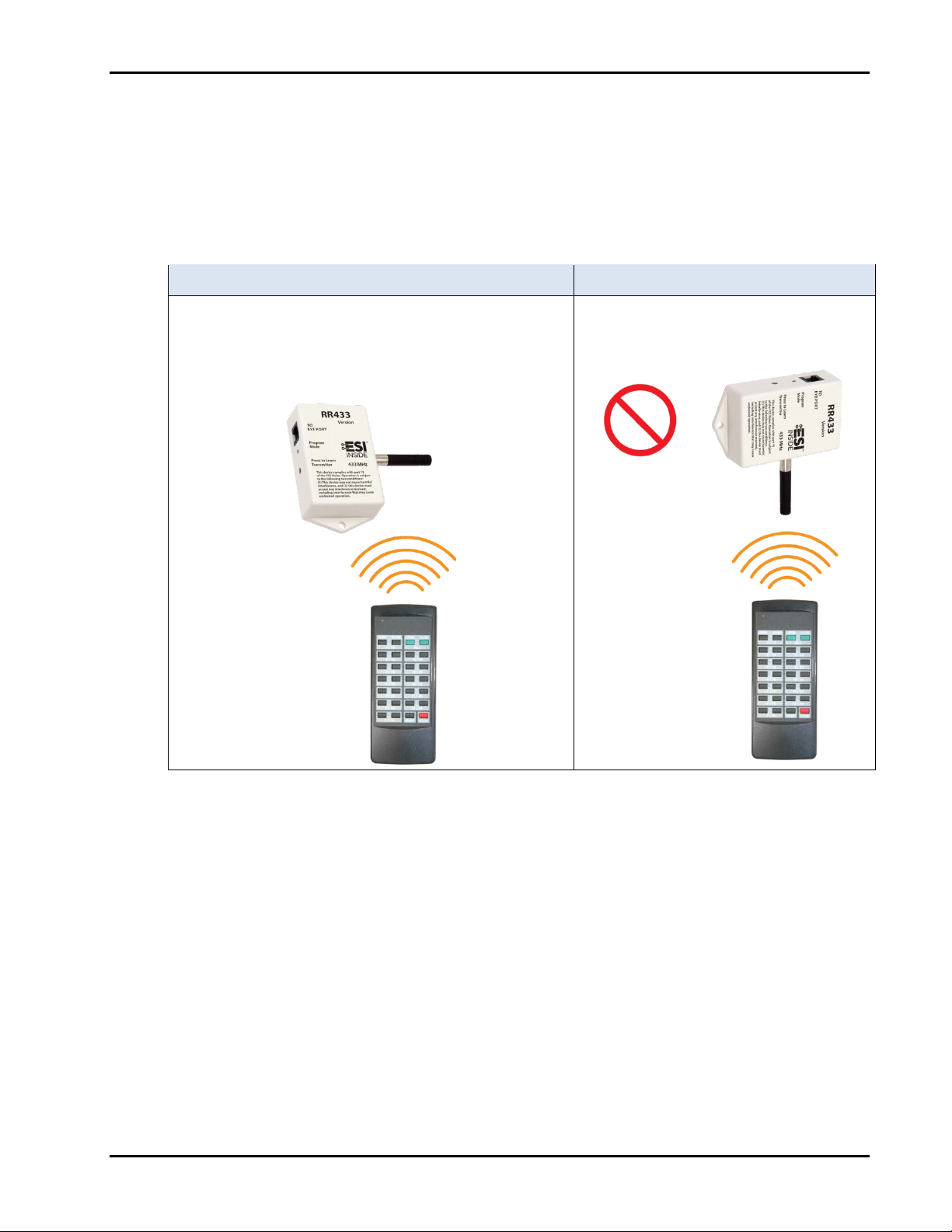
• Improve RF coverage by orienting the RR433 antenna broadside to the transmitter signal, as shown
below.
CORRECT NOT CORRECT
On the RR433, the long side of the antenna should face
the direction where the transmitter is like ly to be used.
The antenna should be broadside (perpendicular) to the
transmitter’s location.
Do not “point” the RR433 antenna toward
the RF transmitter location.
Minimize Interference
RF reception range can be reduced by EMI (electromagnetic interference) that interferes with or masks the
desired frequency. EMI is generated by any electrical device at various RF noise levels depending on the
device. Separate the RR433 module as far as possible from sources of RF noise.
• Sources of EMI include computers, video equipment, digital processors, lighting dimmers, lighting
ballasts, motors, or any large AC source.
• Fluorescent lights cause a noticeable interference at 433 MHz.
Weak Battery on Transmitter
Check the transmitter battery.
• A weak battery can reduce RF range to 10 percent or less of normal operating range.
www.vutec.com © 2013 VUTEC Corporation Page 5 of 5
 Loading...