

Page 1
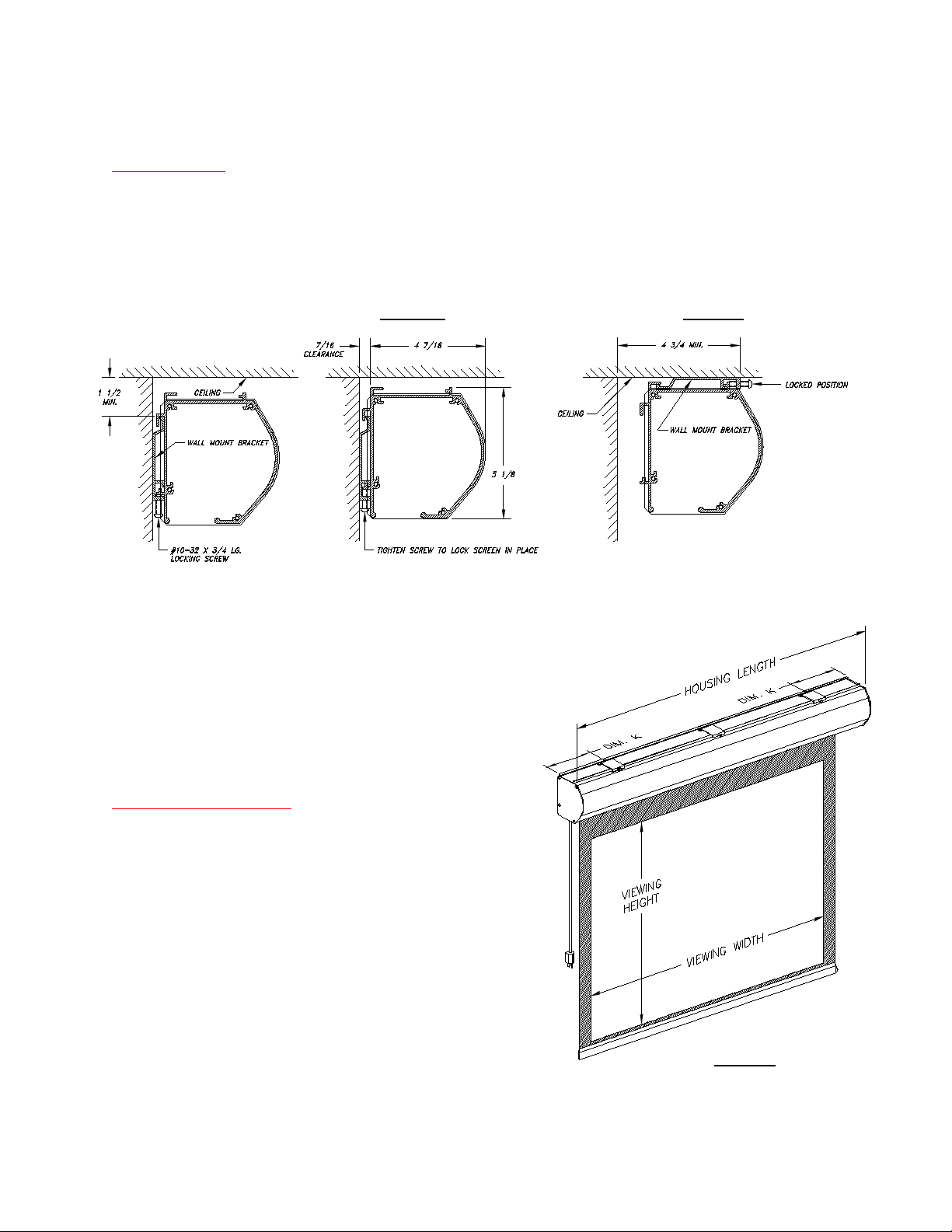
Figure 3
LECTRIC I & III
BUILT-IN RF MOTOR
WALL OR UNDER CEILING MOUNT
GENERAL
The LECTRIC I or III screen may be mounted to the wall or ceiling as shown in Figures 1 and 2 below. The screen
comes with three mounting brackets and screws. Where possible, the mounting brackets should be installed to rigid
structural members. If this is not possible, suitable wall anchors or other mounting methods must be used.
Unless otherwise specified, the motor locates on the left end of the housing. The screen fabric rolls down from the
backside of the roller.
Figure 1
Figure 2
Wall Mounted Ceiling Mounted
Important considerations when deciding the mounting
location for the screen.
The Housing Length (Figure 3) is as follow:
Housing Length = Viewing Width + 10 -¼" (Lectric I)
Housing Length = Viewing Width + 17 -½" (Lectric III)
The screen is centered in the housing.
The housing may be moved left or right after it has been
hang for final location.
INSTALLATION
Determine the housing length and Dim. K. A third mounting
bracket is recommended for middle support for screen of
96 inches viewing width or larger.
Dim. K should be approximately 1/6" to 1/8" of Housing
Length.
Install the mounting brackets as required. Be sure they are level
for proper contact with the housing.
Note: If the screen is wall mount, the mounting brackets must be
at least 1-½" inches from the ceiling as shown in Figure 1. If the
screen is ceiling mount, the mounting brackets must be at least
4- ¾" inches from the wall (Figure 2).
Page 2

Back-off the locking screw for each mounting bracket so that it is even with the inside face of the bracket.
Slightly tip the screen housing and fit it into the mounting brackets. If this is a ceiling installation, move the screen
housing toward the rear immediately after the insertion so the screen is completely hooked to the brackets
(see Figure 2).
Carefully move the screen housing side to side for final location as desired.
Tighten the locking screw of each bracket to lock the screen in place.
ELECTRICAL
THIS SCREEN EQUIPPED WITH A BUILT-IN RF MOTOR. SIMPLY PLUG THE POWER CORD TO 120VAC
OUTLET FOR OPERATIONS.
Note for 220VAC RF motor:
220VAC RF motor does not have a plug for the power cable; add an appropriate plug of the region for used.
Connect the wires as follow: Green/Yellow to Ground, Blue to Neutral, and Brown to AC Line.
OPERATIONS
Press the Arrow Down button on the transmitter to send the screen down to show position.
Press the Arrow Up button on the transmitter to send the screen to the upper limit.
Press the middle button to stop the screen travel.
CHANGING THE SCREEN UPPER & LOWER LIMITS
Changing the lower limit
Send the screen down in normal mode by momentary pressing the Arrow Down button.
The screen will come to the lower limit and stop.
Press and hold both the Up and Down Arrow buttons until the screen jog up and down in respond. Release the
buttons.
Change the lower limit by momentary pressing the Up or Down button.
Press the Stop button until the screen jog up and down in respond to registering the new lower limit. Normal
operation has been resumed after this step.
Changing the upper limit
Send the screen up in normal mode by momentary pressing the Arrow Up button.
The screen will come to the upper limit and stop.
Press and hold both the Up and Down Arrow buttons until the screen jog down and up in respond. Release the
buttons.
Change the upper limit by momentary pressing the Up or Down button.
Press the Stop button until the screen jog down and up in respond to registering the new upper limit. Normal
operation has been resumed after this step.
ACCESSORIES INCLUDED
1 RF TRANSMITTER KIT
3 MOUNTING BRACKETS WITH SCREWS
 Loading...