

Page 1
INSTALLATION INSTRUCTIONS
Surface Mount Plasma
Installation
The Plasma must be straight and not tilted for the Art Screen to work properly. Tilting of the Plasma is not recommended.
Referring to Figure 2, use a triangle to determine the Plasma
OD onto the wall. Verify the outline accuracy for a problem
free installation.
Determine the depth of the Plasma – from the wall to the
front bezel surface.
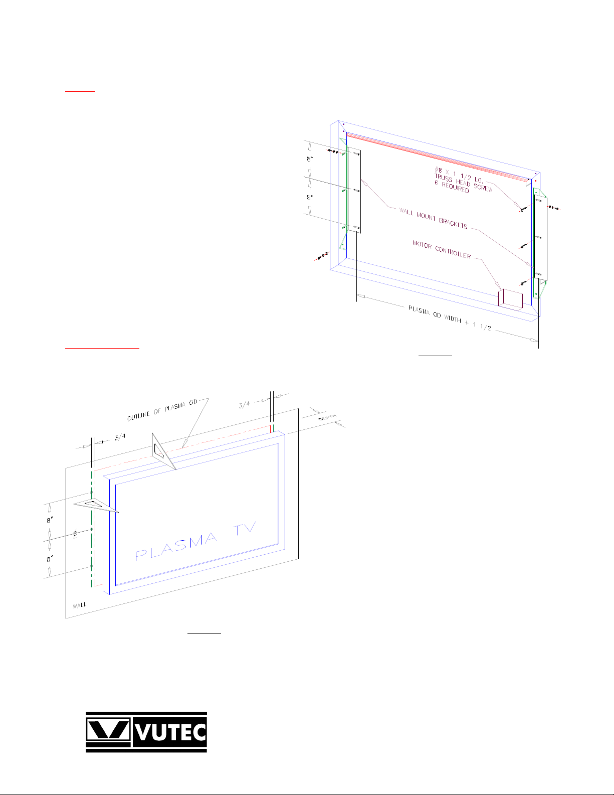
Determine the mounting locations for the wall mount
brackets (Figures 1 & 2). Use proper wall anchors (not
supplied) for drywall installation.
Drill pilot holes for #8 screws or install wall anchors as
required.
Install the Art Screen frame (Figure 3) around the Plasma.
Adjust the Art Screen frame so that it is center around the
Plasma. Tighten the screws.
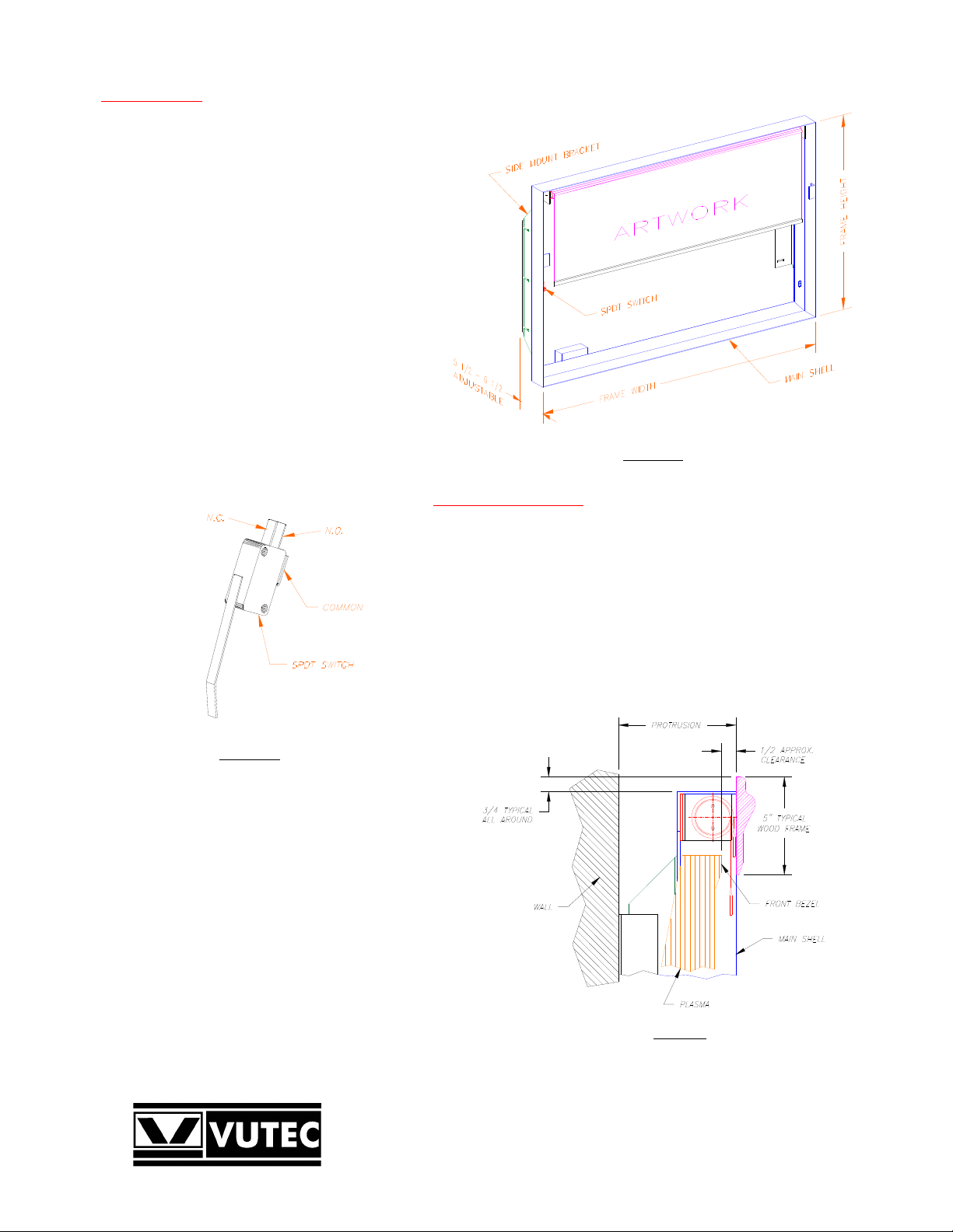
Adjust the depth of the Art Screen frame so that it is 1/2 to
5/8 (Figure 4) inch more than the depth of the Plasma. This
clearance is required for the Art Screen to travel.
Route the motor wires to the backside for connection later.
Wood Frame Installation
A typical wood frame including the liner is approximately 5
Figure 2
Outlining the Plasma OD onto Wall
Figure 1
Rear View of Frame
inches wide to properly cover the assembly. The wood
overhangs the main shell approximately 3/4 inch when
attached.
Two corner woods are attached to the backside of the
wood frame to take-up the weight.
The wood frame attaches to the main shell by two
clips on the backside (see Picture Frame Installation
and Removal Section) and hold in place by the ears of
the main shell.
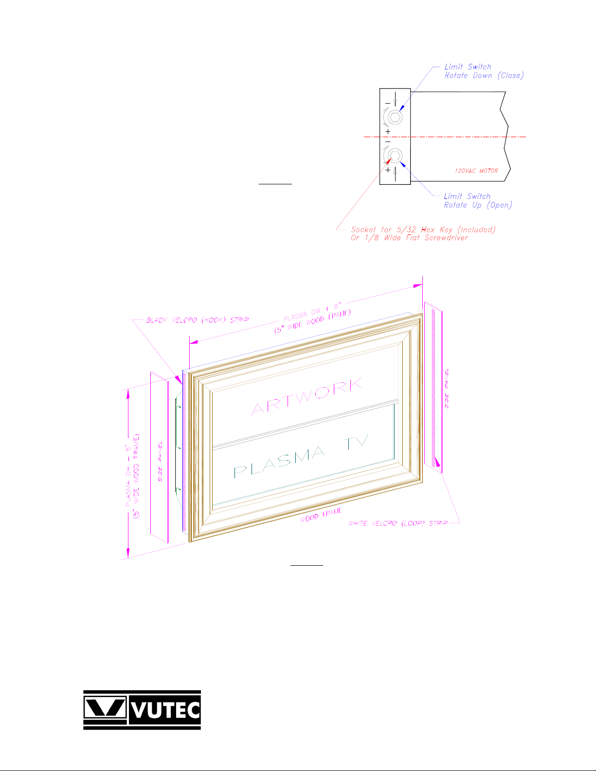
Referring to Figure 6, two side panels are provided for
covering the sides of the Art Screen frame. The panels
apply to the frame by Velcro strips supplied.
The Velcro strips are cut to length. Apply the black
part (Hook) of the Velcro to the sides of the frame.
Apply the white part (Loop) of the Velcro to each of
the panels (Figure 6).
Apply the side panels to the Art Screen frame for a
complete installation. The top and bottom of the Art
Screen frame are left open for proper ventilation for
the plasma.
Optionally, custom-made side panels may be installed
as desired.
VUTEC CORPORATION
www.vutec.com
TEL: (954) 545 9000 - FAX: (954) 545 9011
E-MAIL: info@vutec.com
Page 2
Electrical Connections
The Art Screen comes with IR remote control for
operations. It is ready for use; no wiring connections are
required.
Place the IR sensor so that it can be seen by the
transmitter.
Plug the power cord to a 120VAC outlet.
The IR remote control has manual inputs for Home
Automation systems, i.e. AMX, Crestron, etc. See IR
remote control manual (included) for detail information.
The SPDT switch (Figure 3b) may be used for security
purpose; its contacts may be connected to an audible
alarm system or monitoring system. The breach of
security will be activated when the wood frame is
removed.
The normal states of the contacts are shown when the
wood frame is not presented.
Contact Rating: 10Amp, 1/2HP, 125/250VAC
or 6Amp, 30VDC.
Figure 3a
Art Screen Frame
Open and Close Limits Setting
The Open limit switch has been properly set for correct stop position. It
should not be adjusted unless a change in the motor or the motor had been
removed for service.
Note each full turn of the limit switch (360 degrees) causes the screen to
travel approximately 1/2 inch.
1. To lower the closed limit of the Art Screen. Send the Art Screen
down to it closed position. Turn the Close limit socket
counter-clockwise (Figure 5); the Art Screen will advance downward
as each full turn is made. Stop at the desired position.
2. To raise the closed limit of the Art Screen. Send the Art Screen
Figure 3b
SPDT switch
down to it closed position. Determine the number of turns
to stop the screen above the desired close limit. Turn the
Close limit socket clockwise to raise the limit. The motor
will not move for this direction.
Figure 4
Side View
VUTEC CORPORATION
www.vutec.com
TEL: (954) 545 9000 - FAX: (954) 545 9011
E-MAIL: info@vutec.com
Page 3
3. Send the screen up halfway then stop. Send the screen down to its
closed limit. The screen must stop above the desired position. If it
is not, repeat step 2
4. When the Art Screen stopped above the desired closed limit; do
Step 1 to set the desired closed limit.
5. Check and adjust the closed and open limits as necessary.
Figure 5
Motor Limit Switches
Figure 6
Complete Art Screen
VUTEC CORPORATION
www.vutec.com
TEL: (954) 545 9000 - FAX: (954) 545 9011
E-MAIL: info@vutec.com
Page 4

Accessories Included
Description QTY.
Main Shell including Artwork and Motor 1
Side Mount Bracket 2
Wall Mount Bracket 2
Wood Frame (Complete) 1
Side Panel 2
Velcro Strips 2
IR Receiver in Box 1
IR Sensor (6 Feet Long) 1
IR Transmitter 1
#8 x 1 1/2 Long, Truss Head Phillip Screw 6
#10-32 x 1/2 Long, Pan Head Phillip Screw 12
#10 Flat Washer 12
#10 Helical Washer 12
Limit Switch Setting Tool 1
VUTEC CORPORATION
www.vutec.com
TEL: (954) 545 9000 - FAX: (954) 545 9011
E-MAIL: info@vutec.com
Page 5

PICTURE FRAME INSTALLATION & REMOVAL
SPILC GNIDILS HTIW
Figure 1
Metal frame without picture frame
The backside of the picture frame is in full contact with the front edges of the metal frame. Position the two corner woods and clips to
be guided by the vertical edges of the metal frame. Carefully pushes down (Figure 3b) on the picture frame to set it in place. Corner
woods will make slight noise when they are bottom out to the metal frame. Push up picture frame (2 inches approx.) to remove.
A SPDT switch is provided for security connection (optional). Contact rating: 10A, 1/2HP, 125/250VAC or 6A, 30VDC
Backside of picture frame
Figure 2
Figure 3a
Frame clip and ear prior to engagement Pi degagne ylluf pilC nwod sehsup emarf erutc
Figure 3b Figure 3c
noitallatsni tnuoM ecafruS fo mottob troppuS
VUTEC CORPORATION
www.vutec.com
TEL: (954) 545 9000 - FAX: (954) 545 9011
E-MAIL: info@vutec.com
Page 6

VUTEC CORPORATION
www.vutec.com
TEL: (954) 545 9000 - FAX: (954) 545 9011
E-MAIL: info@vutec.com
Page 7

DISPLAY PANEL REAR VIEW
DISPLAY PANEL WALL INSTALLATION
CAUTION: A LOW PROFILE WALL MOUNT BRACKET MUST BE USED FOR THIS APPLICATION INSTALLATION.
ASSEMBLY INSTRUCTION (LCD SLIM LINE 1 1/2" PANEL DEPT H )
1. A LOW PROFILE WALL MOUNT BRACKET MUST BE USED FOR THIS INSTALLATION
APPLICATION
2. REPLACE EXISTING IEC POWER CORD WITH THE (VUTEC SUPPLIED) NEMA 5-15
ROTATING UNIVERSAL IEC POWER CORD PRIOR TO PROCEEDING WITH
THE LCD DISPLAY INSTALLATION
3. THE LCD DISPLAY SHOULD BE EQUALLY SPACED WITHIN THE INTERNAL FRAME SPACE
4. PROPER WALL ANCHORS (NOT SUPPLIED) MUST BE USED TO FASTEN THE ARTSCREEN
FRAME THE WALL AND INSURE PROPER ALIGHN AS ILLUSTRATED BELOW.
 Loading...