

Page 1
INSTALLATION INSTRUCTIONS
Surface Mount Plasma
Installation
The Plasma must be straight and not tilted for the Art
Screen to work properly. Tilting of the Plasma is not
recommended.
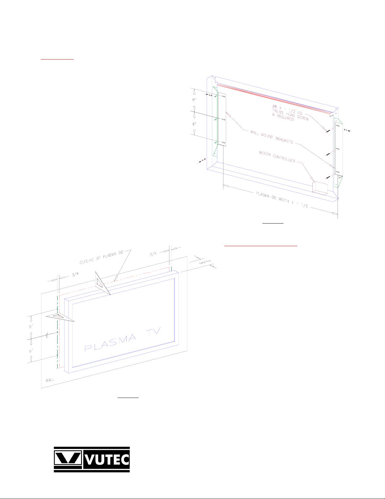
Referring to Figure 2, use a triangle to determine the Plasma
OD onto the wall. Verify the outline accuracy for a problem
free installation.
Determine the depth of the Plasma – from the wall to the
front bezel surface.
Determine the mounting locations for the wall mount
brackets (Figures 1 & 2). Use proper wall anchors (not
supplied) for drywall installation.
Drill pilot holes for #8 screws or install wall anchors as
required.
Install the Art Screen frame (Figure 3) around the Plasma.
Adjust the Art Screen frame so that it is center around the
Plasma. Tighten the screws.
Adjust the depth of the Art Screen frame so that it is 1/2 to
5/8 (Figure 4) inch more than the depth of the Plasma. This
clearance is required for the Art Screen to travel.
Route the motor wires to the backside for connection later.
Figure 1
Rear View of Frame
Figure 2
Outlining the Plasma OD onto Wall
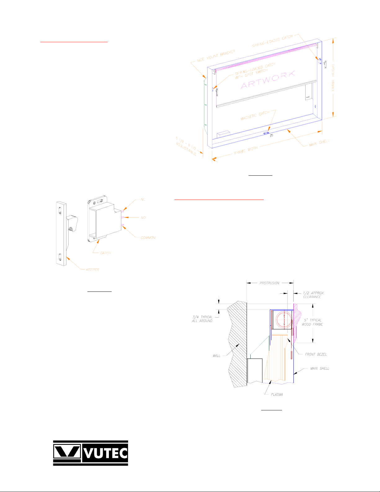
Wood Frame Installation
A typical wood frame including the liner is
approximately 5 inches wide to properly cover the
assembly. The wood overhangs the main shell
approximately 3/4 inch when attached.
Two corner woods are attached to the backside of the
wood frame to take-up the weight.
Two spring-loaded catches and a magnetic catch will
hold the wood frame to the main shell. Simply snap
the wood frame to the shell when ready.
Referring to Figure 6, two side panels are provided for
covering the sides of the Art Screen frame. The panels
apply to the frame by Velcro strips supplied.
The Velcro strips are cut to length. Apply the black
part (Hook) of the Velcro to the sides of the frame.
Apply the white part (Loop) of the Velcro to each of
the panels (Figure 6).
Apply the side panels to the Art Screen frame for a
complete installation. The top and bottom of the Art
Screen frame are left open for proper ventilation for
the plasma.
Optionally, custom-made side panels may be installed
as desired.
VUTEC CORPORATION
Page 2
Electrical Connections
The Art Screen comes with IR remote control for
operations. It is ready for use; no wiring connections are
required.
Place the IR sensor so that it can be seen by the
transmitter.
Plug the power cord to a 120VAC outlet.
The IR remote control has manual inputs for Home
Automation systems, i.e. AMX, Crestron, etc. See IR
remote control manual (included) for detail information.
The spring-loaded catch (Figure 3b) with SPDT switch
may be used for security purpose; its contacts may be
connected to an audible alarm system or monitoring
system. The breach of security will be activated when
the wood frame is removed.
The states of the contacts are shown when the Keeper is
not engaged with the Catch.
Contact Rating: 6Amp, 250VAC or 3Amp, 30VDC.
Figure 3a
Art Screen Frame
Open and Close Limits Setting
The Open limit switch has been properly set for correct stop position. It
should not be adjusted unless a change in the motor or the motor had been
removed for service.
Note each full turn of the limit switch (360 degrees) causes the screen to
travel approximately 1/2 inch.
1. To lower the closed limit of the Art Screen. Send the Art Screen
down to it closed position. Turn the Close limit socket
counter-clockwise (Figure 5); the Art Screen will advance downward
as each full turn is made. Stop at the desired position.
Figure 3b
Spring-loaded catch with SPDT switch
2. To raise the closed limit of the Art Screen. Send the Art
Screen down to it closed position. Determine the number
of turns to stop the screen above the desired close limit.
Turn the Close limit socket clockwise to raise the limit.
The motor will not move for this direction.
Figure 4
Side View
Page 3

3. Send the screen up halfway then stop. Send the screen down to its
closed limit. The screen must stop above the desired position. If it
is not, repeat step 2
4. When the Art Screen stopped above the desired closed limit; do
Step 1 to set the desired closed limit.
5. Check and adjust the closed and open limits as necessary.
Figure 5
Motor Limit Switches
Figure 6
Complete Art Screen
Page 4

Accessories Included
Description QTY.
Main Shell including Artwork and Motor 1
Side Mount Bracket 2
Wall Mount Bracket 2
Wood Frame (Complete) 1
Side Panel 2
Velcro Strips 2
IR Receiver in Box 1
IR Sensor (6 Feet Long) 1
IR Transmitter 1
#8 x 1 1/2 Long, Truss Head Phillip Screw 6
#10-32 x 1/2 Long, Pan Head Phillip Screw 12
#10 Flat Washer 12
#10 Helical Washer 12
Limit Switch Setting Tool 1
Page 5

WOOD FRAME INSTALLATION & REMOVAL
Note: Do not pull the
wood frame straight out.
The catches are designed
to be separated in the
peeling manner as shown
in Figure A.
The Corner Wood Blocks
are designed to carry the
weight of the wood frame
when installed. Carefully
places them in the lower
left and right corners of the
artscreen frame before
snapping the wood frame in
place.
Figure A
Pull open the wood frame from the top
Figure B
Backside of wood frame
Figure C
Wood frame shown removed from Artscreen
Page 6

ART ROLLER INSTALLATION
Vutec has made a significant improvement to control and reduce the vibration noise level associated with the art roller motor.
The art roller motor is now shipped uninstalled to protect the four vibration dampers imparted in the design.
The following steps show how to install the art roller to the art screen unit.
Note: Installing the art roller motor must be the last thing to do! Therefore, the metal frame, the Plasma TV and its mounting location
must have been installed, adjusted and checked to satisfaction before proceeding with the art roller installation.
Step 1 Carefully remove the plastic wrapping. Locate two #8-32 machine screws and flat washers for used. There should be a layer
of paper protecting the art roller. Do not remove the paper until the art roller has been installed and secured properly. The
paper keeps the art print clean for final revelation.
Step 2 Referring to Figure D, insert the art roller into the idler bracket at angle as shown. Rotates and guides the art roller into place
such that it sits on the motor bracket as shown in Figure E.
Step 3 Use #8-32 by 3/8 inch long machine screws to secure the art roller in place (Figure F). Do not over-tighten the screws.
Step 4 No placement adjustments are necessary because the location of the idler bracket has been determined and it remained on the
metal frame for this purpose.
Step 5 Connect the motor cable to the IR control box.
Step 6 Remove the masking tapes and the protective paper. The art roller is ready for operation!
Note: Pictures in this page shown recessed
mount frame. However, the installation of
the art screen roller is the same.
Figure D
Art roller insertion
Figure E
Art roller in place
#8-32 x 3/8 long machine screw
2 required. Do not over-tighten.
Figure F
Screw attachment
 Loading...