

Page 1

ART-R SERIES INSTL_REVD - 1 -
Important Safety Instructions (save this instructions)
! WARNING: When using Art Screen R series, basic precautions should always be followed, including:
• Read the entire users manuals before attempting to use Art Screen R series.
• Keep everything and everyone away from Art Screen while in motion. Do not contact moving parts.
• The user must observe the Art Screen R series while TV Plasma is in motion at all times until it is stopped by pressing on one of the
directional arrows on the remote control.
• Follow the installation instructions provided to correctly install Art Screen R series. To prevent injury, Art Screen R series must be
snugly attached to the wall in accordance with the installation instructions.
• Art Screen R series restricts movement based upon the TV width set on the side controls located on the right of main shell. The TV
width must be set correctly before operating Art Screen R series.
• The Art Screen R series mounting set up is intended for use only with the maximum weight of 180 pounds (81 kg). Use with
TVs heavier than 180 pounds (81 kg) may result in instability and cause injury.
• To reduce the risk of injury, close supervision is necessary when an appliance is used near children.
• Only use attachments recommended or sold by the manufacturer.
• Do not use outdoors.
• To disconnect, turn all controls to the off (“O”) position, then remove plug from outlet.
• Do not unplug by pulling on cord. To unplug, grasp the plug, not the cord.
• Unplug from outlet when not in use and before servicing or cleaning.
• Do not operate any appliance with a damaged cord or plug, or after the appliance malfunctions or is dropped or damaged in any
manner. Return appliance to the nearest authorized service facility for examination, repair, or electrical or mechanical adjustment.
• Connect to a properly grounded outlet only. See Grounding Instructions.
Grounding Instructions
This appliance must be grounded. In the event of malfunction or breakdown, grounding provides a path of least resistance for electric
current to reduce the risk of electric shock.
A quad outlet AC box is provided with this appliance for 120VAC connection. Connect 120VAC to this box to power the TV, X-Arm
and the IR remote control.
DANGER – Improper connection of the equipment-grounding conductor can result in a risk of electric shock.
This appliance is for use on a circuit having a nominal rating more than 120 V, 15 A and is for use on a circuit having a nominal rating
of 120 V), and is factory equipped with a specific electric cord and plug. No adapter should be used with this appliance. If the appliance
must be reconnected for use on a different type of electric circuit, the reconnection should be made by qualified service personnel; and
after the reconnection, the appliance should comply with all local codes and ordinances.
Page 2
ART-R SERIES INSTL_REVD - 2 -
INSTALLATION INSTRUCTIONS (rev A)
Recessed Mount Motorized Plasma
Installation
The Plasma must be retracted and in the vertical position for the Art
Screen to work properly.
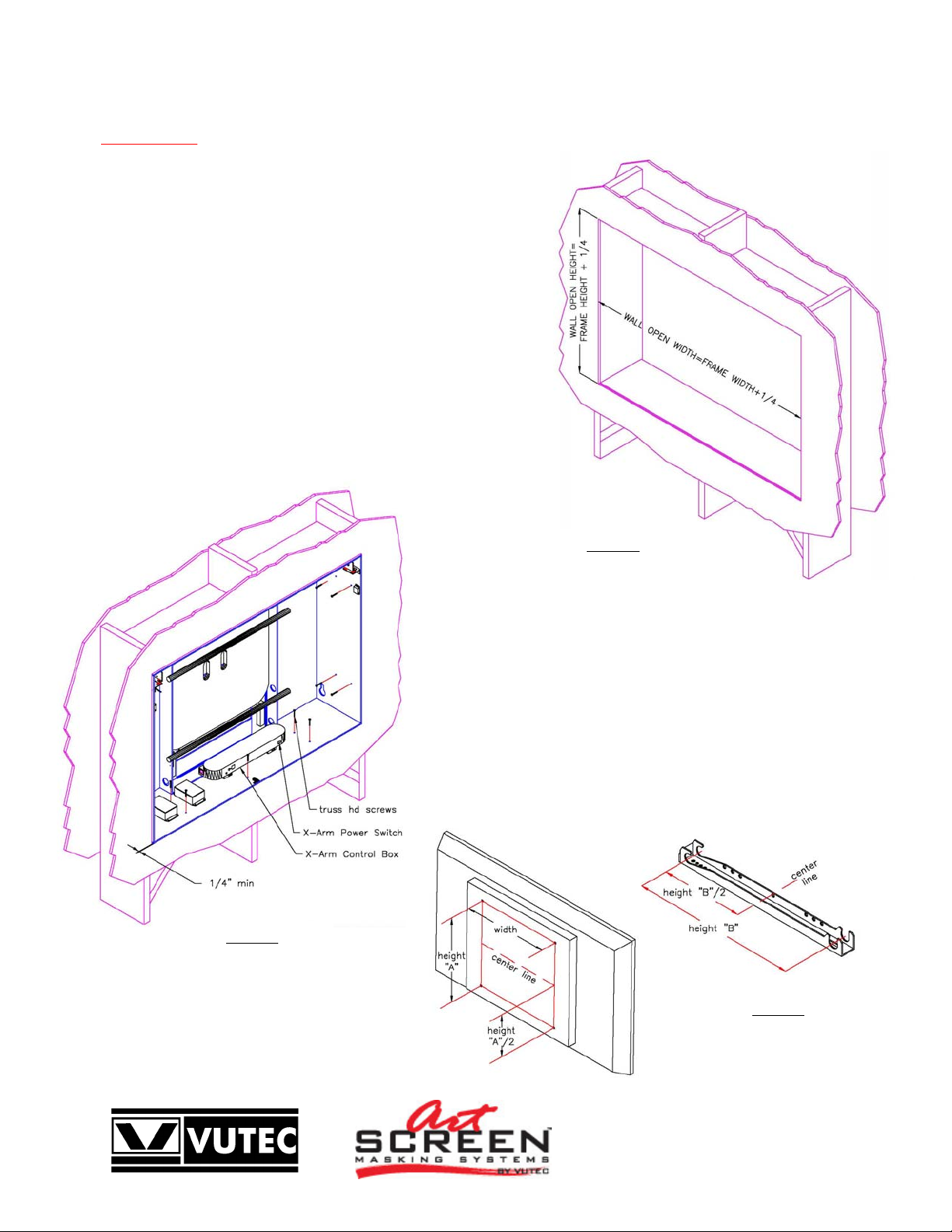
Referring to Dimensional Information (Fig 1 and Figure 15 on page 7 in
this manual); determine the wall opening height, width and depth. (The
wall cutout for the back should be a snug fit. The front is designed to
protrude about a ¼” from wall surface, see Fig.2).
Dry wall installation requires base support as shown in
Figure 1. Additional supports to strengthen the base support should also
be considered.
Determine I/O routing of the video/audio cables and AC power
supply. See pages 8-9 of X-Arm user manual instructions.
Place the main shell in the wall opening. Be sure the main shell is level;
shim as required. Screw the shell to the wall as shown in Fig. 2.
Remove the hook brackets and clips from X-Arm. And mount to back of
TV following proper configuration.
Measure the TV mounting holes as indicated in Figure 3.
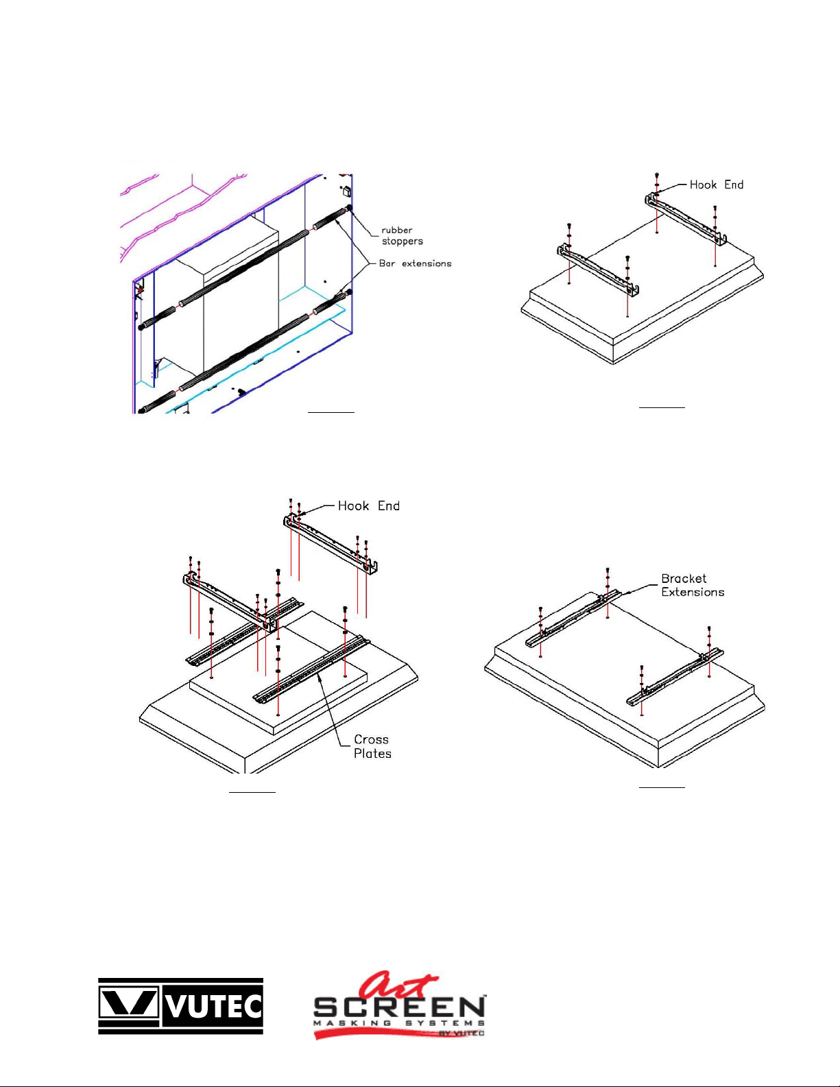
If the width is 26” – 34.50” (66.04-87.63 cm), install the Bar Extensions,
shown in Figure 4.
If the width is more or equal to 21.50” (54.61cm), install hook brackets as
shown in Figure 5. (Hook ends towards top of TV).
If the width is less than 21.50” (54.61 cm), install the Cross Plates, shown in
Figure 6.
If the height “A” is 18.50” – 27.50” (47 – 70 cm), install the Brackets
Extensions, as shown in Fig 7.
More than one adapter may need to be installed and center lines of
mounting holes and hook brackets should coincide.
Figure 1
Wall Construction
Figure 2
Main Shell Assembly
Figure 3
TV mounting holes
and hook bracket
dimensions
Page 3
ART-R SERIES INSTL_REVD - 3 -
**See Instruction sheet provided with kits for details
Figure 4
Bar Extensions**
Figure 5
Hook Brackets
Figure 6
Cross Plates**
Figure 7
Bracket
Extension**
Page 4
ART-R SERIES INSTL_REVD - 4 -
Press the Power to ON (1) on X-Arm Control Box on side of Main Shell (See Figure 2).
Manually keep Art rolled up limit switch LS1 actuated. LS1 is shown in Figure 13 on this manual. Press “Power” and then “X-Arm”
button on the X-Arm remote control to bring Arm forward. Let go LS1.
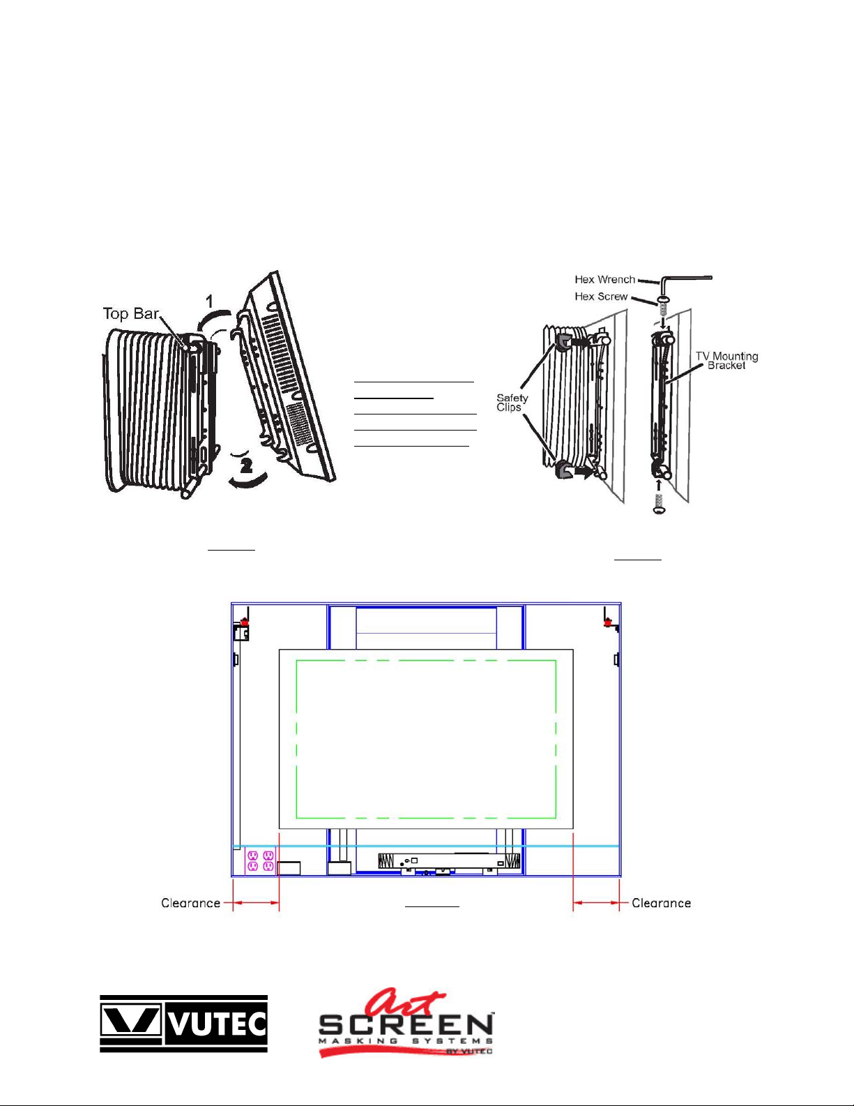
The TV is very heavy. Use at least two people to hang TV on X-Arm.
Hang the TV on the top bar of X-arm and then carefully rotate it down as shown in Fig. 8.
Center TV to Main Shell by sliding TV sideways as necessary, clearances dimensions must be same in both sides of TV,
as shown in Fig 10. Check top and bottom clearances, bottom clearance could be a little larger than top.
Insert each of the four safety clips, on the top and bottom of the TV Mounting Bracket (Hook brackets) as shown in Fig. 9
Secure the safety clips using the included hex wrench to tighten the screws.
Actuate Art rolled up
limit switch LS1 once
again to activate power
and press “X-Arm”
button on X-Arm remote
control to recede X-Arm.
Check TV width and
Calibrate TV
following instructions
on pages 11 and 12 of
X-Arm user manual.
Figure 8
Hang TV on X-Arm
Figure 9
Insertion of safety
clips
Figure 10
TV centered on
Main Shell
Page 5

ART-R SERIES INSTL_REVD - 5 -
Wood Frame Installation
A typical wood frame including the liner is
approximately 5-1/2 inches wide to properly cover
the assembly. The wood overhangs the main shell
approximately 3/4 inch when attached.
Two corner woods are attached to the backside of
the wood frame to take-up the weight.
Two spring-loaded catches and a magnetic catch
will hold the wood frame to the main shell. Simply
snap the wood frame to the shell when ready.
Electrical Connections
A Quad outlet AC box is provided for 120VAC
connection. Connect 120VAC to this box to power
the TV, X-Arm and the IR remote control.
The Art Screen and the X-Arm come with
respective IR remote controls for operations.
Remotes are ready for use; no wiring connections
are required.
Place the IR sensors so that it can be seen by the
transmitters.
Plug the power cords to a 120VAC outlet.
The IR remote control and X-Arm have manual inputs for Home Automation systems, i.e. AMX, Crestron, etc. See IR remote control
manual and X-Arm manual (included) for detail information.
The spring-loaded catch (Figure 12) with SPDT switch may be used for security purpose; its contacts may be connected to an audible
alarm system or monitoring system. The breach of security will be activated when the wood frame is removed.
The states of the contacts are shown when the Keeper is not engaged with the
Catch.
Contact Rating: 6Amp, 250VAC or 3Amp, 30VDC.
Figure 12
Spring-loaded catch
with SPDT switch
The Art Screen R series has two normally open limit switches, as shown in Fig 13:
LS1 – Art rolled up limit switch needs to be engaged in order for X-Arm to
operate.
LS2 – X-Arm home limit switch needs to be engaged in order for Artwork to
operate. (See electrical schematic appendix)
Figure 11
Partial Assembly
Side View
Figure 13
Page 6

ART-R SERIES INSTL_REVD - 6 -
Open and Close Limits Setting
The Open limit switch has been properly set for correct stop position. It should not be adjusted unless a change in the motor or the
motor had been removed for service.
Note each full turn of the limit switch (360 degrees) causes the screen to travel approximately 1/2 inch.
1. To lower the closed limit of the Art Screen. Send the Art Screen down to it closed position. Turn the Close limit socket
counter-clockwise (Figure 14); the Art Screen will advance downward as each full turn is made. Stop at the desired position.
2. To raise the closed limit of the Art Screen. Send the Art Screen down to it closed position. Determine the number of turns to
stop the screen above the desired close limit. Turn the Close limit socket clockwise to raise the limit. The motor will not move for
this direction.
3. Send the screen up halfway then stop. Send the screen down to its closed limit. The screen must stop above the desired position. If
it is not, repeat step 2
4. When the Art Screen stopped above the desired closed limit; do Step 1 to set the desired closed limit.
5. Check and adjust the closed and open limits as necessary.
Figure 14
Motor Limit Switches
Page 7

ART-R SERIES INSTL_REVD - 7 -
Dimensional Information:
Figure 15
Dimensional Information
Page 8

ART-R SERIES INSTL_REVD - 8 -
Accessories Included
Description QTY.
Frame Assembly including Artwork and Motor 1
X-Arm 1
Wood Frame (Complete) 1
IR Receiver in Box 1
IR Sensor (6 Feet Long) 1
IR Transmitter 1
AAA Battery 2
#8 x 1 1/2 Long, Truss Head Phillip Screw 20
X-Arm IR Receiver in Control Box 1
X-Arm IR Sensor 1
X-Arm IR transmitter 1
AA Battery 2
Screen Size Selection pointer 1
Hex wrench (for safety clips) 1
Zip tie fasteners 10
Remote Control X-Arm 1
Figure 16
Complete Art Screen Installation
Page 9

ART-R SERIES INSTL_REVD - 9 -
WOOD FRAME INSTALLATION & REMOVAL
Note: Do not pull the wood frame straight out. The catches are designed to be separated in the peeling manner as shown in
Figure A.
The Corner Wood Blocks are designed to carry the weight of the wood frame when installed. Carefully places them in the lower left
and right corners of the artscreen frame before snapping the wood frame in place.
Figure A
Pull open the wood frame from the top
Backside of wood frame
Figure B
Figure C
Wood frame shown
removed from Artscreen
Page 10

ART-R SERIES INSTL_REVD - 10
-
ART ROLLER INSTALLATION
Vutec has made a significant improvement to control and reduce the vibration noise level associated with the art roller motor.
The art roller motor is now shipped uninstalled to protect the four vibration dampers imparted in the design.
The following steps show how to install the art roller to the art screen unit.
Note: Installing the art roller motor must be the last thing to do! Therefore, the metal frame, the Plasma TV and its mounting location
must have been installed, adjusted and checked to satisfaction before proceeding with the art roller installation.
Step 1 Carefully remove the plastic wrapping. Locate two #8-32 machine screws and flat washers for used. There should be a layer
of paper protecting the art roller. Do not remove the paper until the art roller has been installed and secured properly. The
paper keeps the art print clean for final revelation.
Step 2 Referring to Figure D, insert the art roller into the idler bracket at angle as shown. Rotates and guides the art roller into place
such that it sits on the motor bracket as shown in Figure E.
Step 3 Use #8-32 by 3/8 inch long machine screws to secure the art roller in place (Figure F). Do not over-tighten the screws.
Step 4 No placement adjustments are necessary because the location of the idler bracket has been determined and it remained on the
metal frame for this purpose.
Step 5 Connect the motor cable to the IR control box.
Step 6 Remove the masking tapes and the protective paper. The art roller is ready for operation!
Figure D
Art roller insertion
Figure E
Art roller in place
Figure F
Screw attachment
Page 11

ART-R SERIES INSTL_REVD - 11
-
Electrical Schematic
Electrical Schematic
Figure G
Page 12

ART-R SERIES INSTL_REVD - 12
-
Troubleshooting:
If there is no power to Art Screen,
1 - Check that X-Arm home position limit switch LS2 is being actuated properly by the bottom bar of the X-Arm.
2- Check continuity in IR Art Screen box on side of Main Shell.
Figure G
IR Box
If there is no power to X-Arm,
1 – Check that Art rolled up Limit Switch LS1 is being actuated properly by the Art cross bar.
2 – Check continuity in X-Arm Power Box on bottom of Main Shell.
3 – If X-Arm still unresponsive then follow troubleshooting instruction in X-Arm user manual.
Figure G
X-Arm Power Box
 Loading...