

VulcanUAV Vulcan Raven User Manual
Vulcan Raven
Manual V2.0
Vulcan Raven
Heavy Lift MultiCopter
Manual V2.0
www.VulcanUAV.com.

Vulcan Raven
Manual V2.0
Thank you for purchasing the Vulcan Raven.
The Raven is a very tough, heavy lifty folding airframe in the X8 con-
figuration. Please follow these build instructions carefully, and we wish
you many hours of safe and enjoyable flying!
Note on parts - Part designs are always changing and being improved. Do not worry if the
parts you have or hole patterns do not exactly match those shown in this manual, details
contained here will still apply.
SAFETY NOTICE
Multicopters can be dangerous and pose a significant risk of injury and
damage to property. Always take all necessary safety precautions to avoid damage or
injury to yourself and those around you!
Never fly near or over buildings, roads or people.
Always ensure you have plenty of space to fly with an uninterrupted view of your machine
at all times.
Always stay well clear of moving propellers.
Before flying.....
Ensure all nuts, bolts and linkages are tight and cannot come undone.
Check your propellers are securely tightened, have no chips, cracks or dents and if they
do, replace them as necessary. Propellers should be attached with nylock nuts or double
nuts, never relyon a single standard nut to attach your propellers.
Ensure all electrical connections are secure with good contacts, well insulated and cannot
come apart.
Make sure all onboard equipment such as batteries, cameras or any other payload is
properly and securely attached and cannot come loose, shake, vibrate or move around
during flight.
Always make sure all batteries are fully charged and range check your radio.
www.VulcanUAV.com.

Vulcan Raven
Manual V2.0
Specification:
Airframe:
Configuration: X8 co axial folding
Diameter: 1150mm
Max Take Off Weight: 24 Kg
Max Batteries: 4 x Lipo
Landing Gear: Fixed or Retractable
Navigation: DayBright LEDs Red & Green (Port & Starboard)
Materials:
Frame plates: 3K Twill Pure Carbon Fibre
Lower Plate: 3mm thickness
Top Plate: 2mm thickness
Arms: Aluminium custom extruded.
Bolts: Hardened steel zinc coated or self colour
Nuts: Nylock
Pillars: Aluminium M3 threaded
Battery Mounting:
Anti slip mat
Dual battery straps
Folding Mechanism:
Dual cam lever locks for each arm, with additional safety latch.
Thrust bearing on lower side of cam levers to prevent nylock nuts undoing when lever
is twisted from above.
Power Distribution Board:
Board Material: FR4 TG170
Dual sided (positive side and negative side to prevent shorting)
Rating: 400A continuous at <50 degrees C
Anti Vibration Plate:
12 or 16 x Silicone Gel bushes each rated to load up to 650g
3mm Pure carbon fibre plate
12 or 16 x Steel standoff pillars
Payload Mount:
2mm aluminium L brackets
2 x 12mm pure carbon fibre tube with 2mm wall thickness.
www.VulcanUAV.com.
Vulcan Raven
Manual V2.0
Assembly Guide:
The Power Disribution Board (PDB)
The first thing to do in your build is prepare the power distribution board. This is a
critical part of your multi rotor as it ensures reliable and consistent power supply
to all the onboard systems that need power from the main battery packs, including
ESCs and your flight controller. Many will have their own ideas about the best way
to distribute power on their machine, and whilst this manual is not really aimed at
power distribution, we have included some general good practice tips:
Always protect your internal wiring. Any movement of internal wiring can lead to
wear of the insulation and eventually a failure, so we would recommend protecting
all power wires with heatshrink or similar - any suitable tough covering that is resistant to wear and heat.
ESC control wires are thin and quite vulnerable, and are best protected with something other than heatshrink as the heat from the shrinking process may damage
them. Nylon braiding is a good alternative, and although it is less resistant to heat
than heat shrink, it is easier to fit over pre fitted plugs, and better looking, so a good
choice for any wires that will be visible. If your PDB is of the correct specification and
correctly assembled, there should not be excessive heat present.
Good solder joints are critical, and enough heat must be present to fully melt the
solder and allow a good bond between the PDB and wires. If you are using our Vul-
can Power high current PDBs, the thick copper in them will suck the heat from your
soldering iron very quickly. So use a powerful iron with a large head that can retain
it’s heat. A Weller 80W iron with 10mm head is as good choice.
It is a good idea to run multiple independent battery connections for redundancy,
rather than use battery splitters when using multiple LiPo batteries.
It is wise to run several auxilliary power feeds from the board to supply power to
anything you may need now or in future.This will save you having to open the frame
and solder in more feeds in future should you find you need them.
Use thread lock on PDB mountings to ensure there is no way the PDB can come
free over time, or a short will occur. Carbon fibre is highly conductive.
www.VulcanUAV.com.

Vulcan Raven
Manual V2.0
Parts Included
It should be noted that kit contents and part design may change slightly over time as
aircraft design is adjusted. Do not worry if the exact parts you have are different to
those shown, this manual will still apply.
Motor Mounts & Arms
First, it is good practice to protect your motor wires from abrasion, especially where they
enter and leave the arm, pass by the bolts, or if they need to go around any sharp edges
such as the motor mount. Heat shrink is a good choice for this. See FIG 1 below.
Also check the edges of the metal arms where wires enter and leave and make sure there
are no sharp edges.If they feel sharp, gentle use of a small file will smooth them.
www.VulcanUAV.com.
Vulcan Raven
Manual V2.0
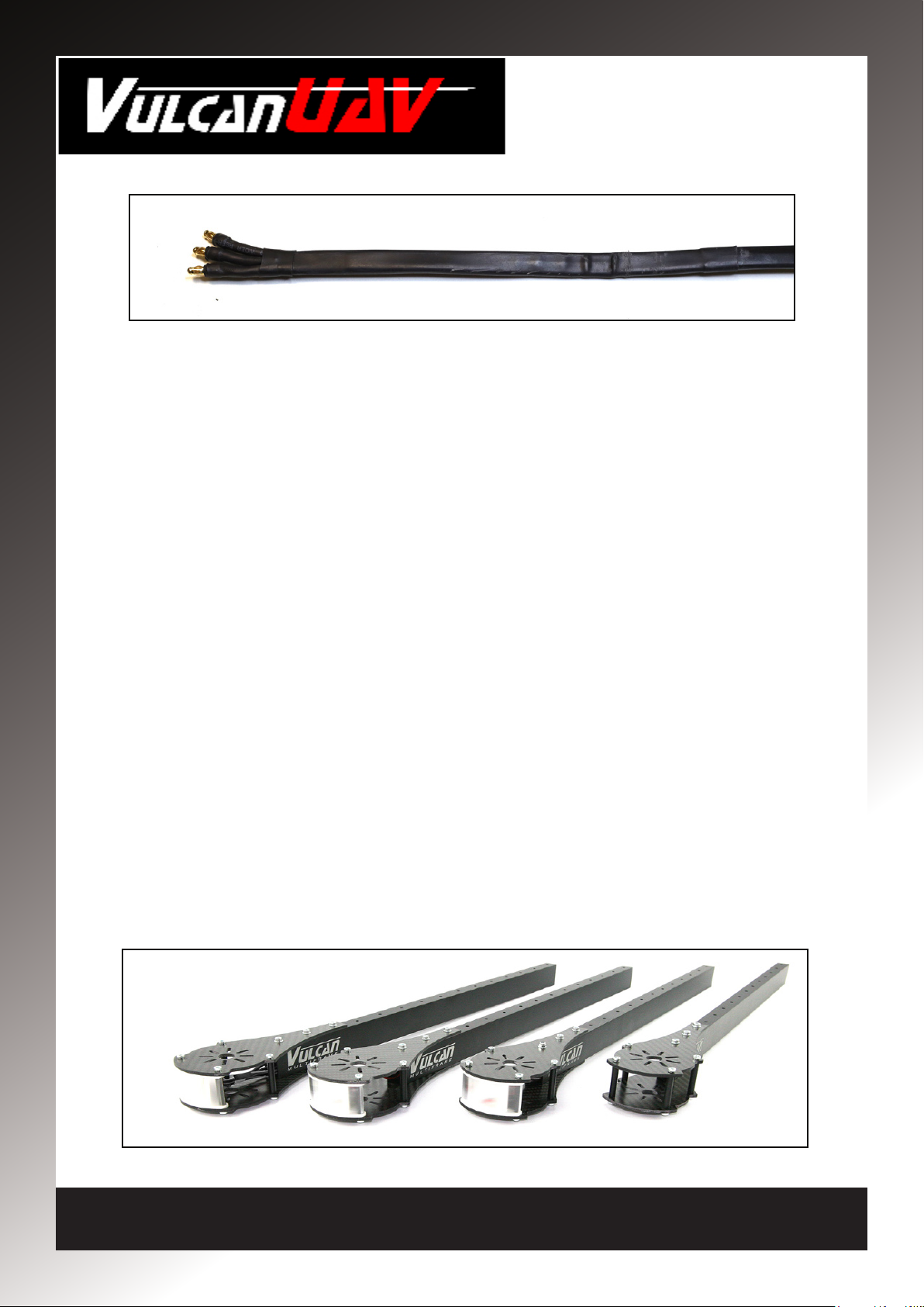
FIG 1
We strongly recommend when heat shrinking your wires you do so with the wires flat in
a line of three, and not as a bunch. This will make inserting bolts through the arms when
wires are present much easier. See FIG 1 above.
Once you have protected your wires, fit two motors to two motor mounts with 8mm M3
bolts and washers. Ensure you get the angle of each motor such that the wires run easily around the sides of the motor mounts. Do this before fitting the mount to the arm as
it is easier to thread the motor wires before mounting bolts are in place. Use thread lock
on the motor bolts, but be careful not to get any thread lock in the motor.
4 x 30mm pillars with M3 10mm bolts are used to join the motor mounts, and this is the
point to also fit the LEDs. Always use thread lock on the pillar bolts. The LEDs are fitted
between the motor mounts with two pillars running down through the LED housing. See
FIG 2 below. We recommend that the wires from the LEDs run from the top of the LED
under the top motor mount and down the arm. Always protect the LED wire from damage. You may find using braiding easier than heat shrink for this, but the choice is yours.
You will find it easier to insert all three sets of wires down the arm together rather than
trying to insert the LED wires after the motor wires. It is also a good idea to mark which
set of motor wires come from the top and bottom motor at this point in order to identify
them later. Repeat for all four pairs of motor mounts.
Now fit the assembled pairs of motors and mounts to the arm. Take care when inserting
the bolts through the arms not to damage the wires. Fit the mounts to the arms using 3
x M3 45mm bolts with washers and nylock nuts.
DO NOT OVERTIGHTEN THE NUTS! If you do you can crush the arm!
The nylock nuts will ensure they do not come loose, although you should always check
nuts regularly for tightness.
Note: One arm in this image does not have LEDs fitted to show how the pillars are installed.
FIG 2
www.VulcanUAV.com.
 Loading...