

Page 1
6720820043-00.1Wo
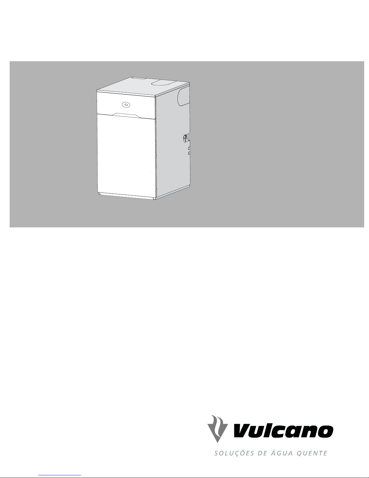
FLOOR STANDING OIL-FIRED CONDENSING
COMBINATION BOILER
User Instructions
Aqualand Green 20 & 30
6720820498 (2016/07) PT
Page 2
Contents
User instructions and customer care guide
Please read these instructions carefully before operating
your boiler.
These instructions are only applicable to the boiler model(s)
stated on the front cover of this manual and must not be used
with any other make or model of boiler.
If you are in any doubt, contact technical support via the
telephone number stated on the back of the manual.
This boiler must be installed by a competent person, e.g. a
registered engineer, failure to install correctly could lead to
prosecution.
Please leave this guide, the installation instructions and
the completed checklist with the user.
NOTICE: A checklist and service interval
record can be found at the rear of the
Installation, Commissioning and Servicing
Instruction manual.
Dedicated to heating comfort
Thank you for purchasing an oil fired condensing boiler from
the Bosch Group. The company prides itself on manufacturing
boilers to the strictest quality control standards throughout
every stage of production.
The condensing range in particular, is extremely energy
efficient, converting more of the fuel consumed into heat
offering you economical running costs and value for money.
It sits in ErP heating efficiency, band A, at the top of the energy
rated boilers available.
There is also the assurance of our no-nonsense parts and
labour guarantee - backed up by an optional servicing and
maintenance contract to keep your boiler operating at peak
condition and efficiency.
To find out more, log onto the website stated on the back of this
manual.
Contents
1 Introduction - - - - - - - - - - - - - - - - - - - - - - - - - - - - - - 3
1.1 Explanation of symbols - - - - - - - - - - - - - 3
1.2 Safety precautions - - - - - - - - - - - - - - - - - 3
2 Important customer information - - - - - - - - - - - - 4
2.1 Energy efficiency - - - - - - - - - - - - - - - - - - 4
2.2 Servicing - - - - - - - - - - - - - - - - - - - - - - - - - 4
2.3 User caution - - - - - - - - - - - - - - - - - - - - - - 4
2.4 Boiler installation details - - - - - - - - - - - - 4
3 Using your boiler - - - - - - - - - - - - - - - - - - - - - - - - - - 5
3.1 Controls - - - - - - - - - - - - - - - - - - - - - - - - - - 5
3.2 Operating the boiler - - - - - - - - - - - - - - - - 6
3.2.1 Switching the boiler on/off - - - - - - - - - - - 6
3.2.2 Setting central heating temperature - - - 6
3.2.3 Controlling central heating - - - - - - - - - - - 7
3.2.4 Setting the hot water temperature - - - - 7
3.2.5 Domestic hot water (DHW) - - - - - - - - - - 7
3.2.6 Eco mode - - - - - - - - - - - - - - - - - - - - - - - - 7
3.2.7 Frost protection - - - - - - - - - - - - - - - - - - - 8
3.2.8 System pressure - - - - - - - - - - - - - - - - - - - 8
4 Maintenance - - - - - - - - - - - - - - - - - - - - - - - - - - - - - 9
4.1 Troubleshooting - - - - - - - - - - - - - - - - - - - 9
4.2 Fault finding - - - - - - - - - - - - - - - - - - - - - - 10
4.3 Maintaining your boiler - - - - - - - - - - - - - - 10
4.4 Servicing - - - - - - - - - - - - - - - - - - - - - - - - - 10
5 General information - - - - - - - - - - - - - - - - - - - - - - - 11
5.1 Ventilation information - - - - - - - - - - - - - - 11
5.2 General notes - - - - - - - - - - - - - - - - - - - - - 11
2
6 Energy saving - - - - - - - - - - - - - - - - - - - - - - - - - - - - 12
6.1 Tips on energy saving - - - - - - - - - - - - - - - 12
7 Guarantee - - - - - - - - - - - - - - - - - - - - - - - - - - - - - - - 13
7.1 Fault or breakdown - - - - - - - - - - - - - - - - - 13
Aqualand Green– 6720820498 (2016/07)
Page 3
1Introduction
1.1 Explanation of symbols
Introduction
Warning symbols
Safety instructions in this document are
framed and identified by a warning triangle
which is printed on a grey Background.
Key words indicate the seriousness of the hazard in terms of
the consequences of not following the safety instructions.
• NOTICE indicates possible damage to property or
equipment, but where there is no risk of personal injury.
• CAUTION indicates possible personal injury.
• WARNING indicates possible severe personal injury.
Important information
Notes contain important information in cases
where there is no risk of personal injury or
material losses and are identified by the
symbol shown on the left. They are bordered
by horizontal lines above and below the text.
Additional symbols
Symbol Meaning
1. a numbered step in an action sequence
▶ a step in an action sequence
•a list entry
– a list entry (second level)
1.2 Safety precautions
Oil fumes or leaks from the boiler:
•Extinguish any naked flames.
• Open windows and doors.
• Switch off the boiler electricity supply.
• Isolate the fuel supply to the boiler.
• Contact installer/service engineer.
Boiler Operation
Health and safety
Where applicable, the CE mark indicates compliance with
relative EU Directives.
Combustible and corrosive materials
Do not store or use any combustible materials (paper, thinners,
paints etc.) inside or within the vicinity of the boiler.
The c ombus tion air must be k ept c lea r of c hemic ally a ggre ssi ve
substances which can corrode the boiler and invalidate any
warranty.
Fitting and modifications
Fitting the boiler and any controls to the boiler may only be
carried out by a competent engineer in accordance with the
relevant Installation Regulations.
Flue systems must not be modified in any way other than as
described in the fitting instructions.
Any misuse or unauthorised modifications to the boiler, flue or
associated components and systems could invalidate the
warranty. The manufacturer accepts no liability arising from
any such actions, excluding statutory rights.
This boiler is suitable for use with Heating oil to EN590:2013,
no other fuel may be used.
Do not operate the appliance when
• The appliance, flue or system is incorrectly fitted, faulty or
damaged.
• The flue terminal outlet is obstructed or damaged.
• There are fumes, fuel leaks or fuel smells from the fuel
supply, appliance or internal flue system.
• The system is empty, frozen or unpressurised.
• The condensate pipe is blocked or restricted.
• The appliance clearances are inadequate.
• The air supply is restricted or vents damaged.
This appliance can be used by children aged
from 8 years and above and persons with
reduced physical, sensory or mental capabilities
or lack of experience and knowledge, if they
have been given supervision or instruction
concerning use of the appliance in a safe way
and understand the hazards involved. Children
shall not play with the appliance. Cleaning and
user maintenance shall not be made by children
without supervision.
Aqualand Green– 6720820498 (2016/07)
3
Page 4
Important customer information
2 Important customer information
2.1 Energy efficiency
Energy efficiency information is given in the Installation,
Commissioning and Servicing Instructions supplied with the
appliance.
2.4 Boiler installation details
Get your installer to fill this table out with the important boiler
details for you refer to when requesting an annual service visit.
2.2 Servicing
The Service Record can be found at the rear of the boiler’s
Installation, Commissioning and Servicing instructions. The
Service Record will be required in the event of any guarantee
work and may be required by the local Building Control
Inspector.
▶ Have the boiler serviced regularly by a competent,
registered engineer.
▶ Ensure that the service engineer completes the Service
Record, at the rear of the Installation, Commissioning and
Servicing Instruction manual, after each service.
▶ Have any work carried out only by a competent, registered
engineer.
▶ Always use original spares, to help maintain the efficiency,
safety and reliability of the appliance.
2.3 User caution
• It is forbidden for any interference with the appliance other
than those actions allowed in this document.
CAUTION: Incorrect use
▶ Any incorrect use can result in danger to
the householder.
Boiler information for your records
Model
Serial number
(refer to figure 9 on page 13)
Type/Output
Date of installation
Installer details
4
Aqualand Green– 6720820498 (2016/07)
Page 5
3Using your boiler
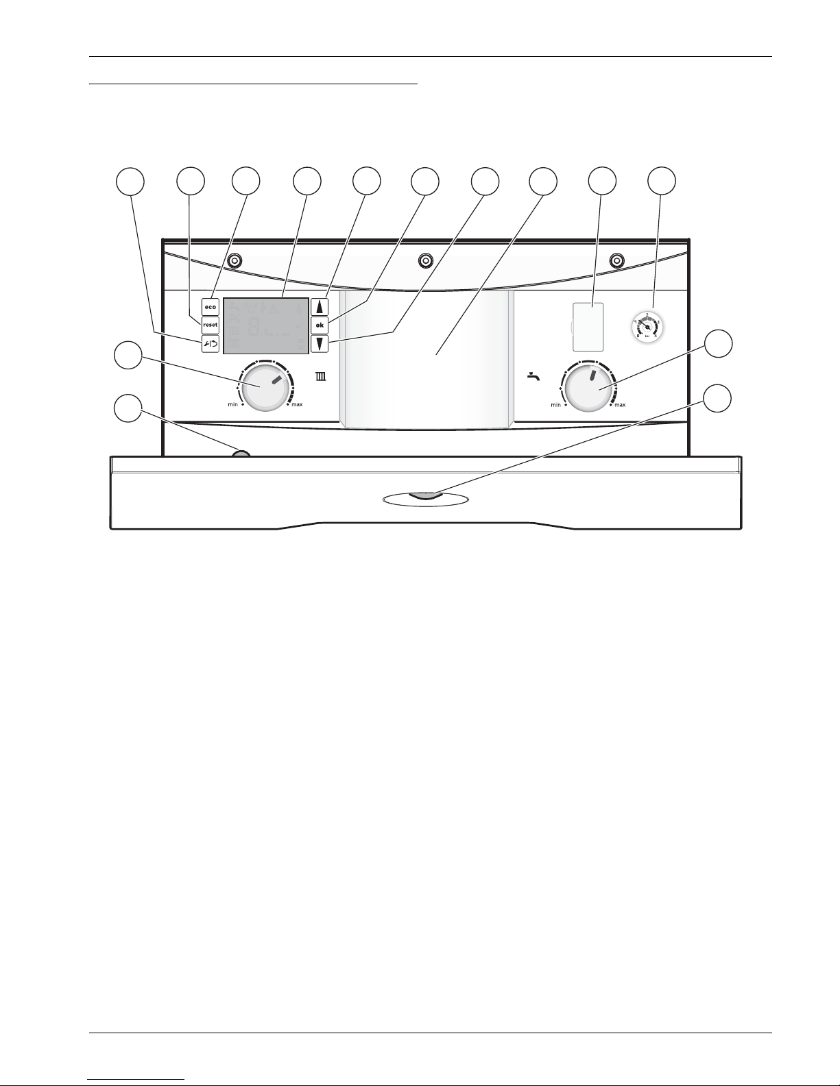
3.1 Controls
Using your boiler
1
2
14
13
Fig. 1 Control panel layout
3
4
°C
°F
5
6 7
8
9 10
11
12
6720820043-01.1Wo
[1] Service mode/return button
[2] Reset button
[3] ECO button
[4] Boiler LCD display
[5] Scroll up button
[6] OK - Select/confirmation button
[7] Scroll down button
[8] Position for optional programmer
[9] Diagnostic port (service engineer’s use only)
[10] System pressure gauge
[11] Hot water, heat store, temperature control
[12] Demand/fault indicator (blue)
[13] Burner service mode button (service engineer’s use only)
[14] Central heating temperature control
Aqualand Green– 6720820498 (2016/07)
5
Page 6
Using your boiler
6720820043-02.1Wo
2
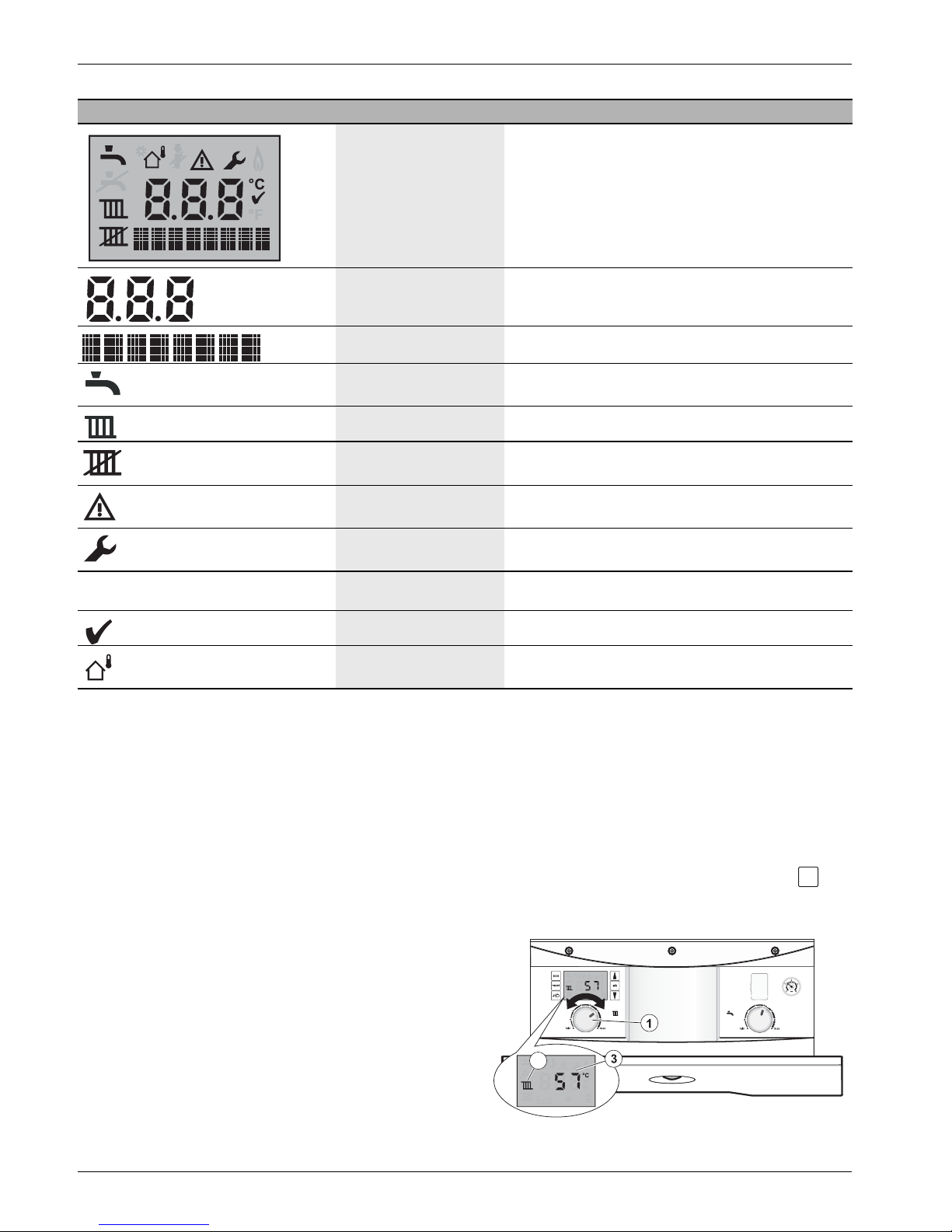
Screen display symbols Description Explanation
All possible screen
symbols (including greyed
out symbols)
All possible screen symbols are displayed briefly during
start up. The greyed out symbols are not required for the
operation of this appliance.
Numerical display A temperature setting or boiler status code is displayed
here.
Text display Displays the word Eco when in eco mode or an Alert code
Hot water This symbol is displayed during a hot water demand and
when the heat store is reheating.
Central heating ON This symbol is displayed during central heating demand.
Central heating OFF This symbol is displayed when in summer mode, the
central heating is off (CH control at minimum)
Alert This symbol is displayed during a fault condition with
diagnostic and status code.
Service mode This symbol is displayed when the service menus are
accessed.
°C
Centigrade indication This symbol is displayed next to temperature reading.
Confirmation This symbol confirms a manual change.
Weather Compensation This symbol is displayed only if Weather Compensation
3.2 Operating the boiler
3.2.1 Switching the boiler on/off
To switch on the boiler:
▶ Turn on the water, oil and electricity supply to the boiler.
▶ Check the programmer/timer is correctly configured and is
set to ON.
▶ Set the room thermostat to the desired setting.
▶ Open and set thermostatic radiator valves as required.
▶ Turn the boiler controls to the required setting.
-or-
▶ If no programmer or thermostat are fitted, just turn the
boiler controls to the required settings.
To switch off the boiler:
▶ Turn the programmer/timer to OFF for heating and hot
water.
sensor is fitted and is active.
3.2.2 Setting central heating temperature
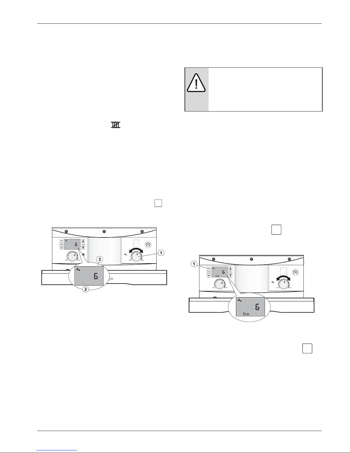
▶ Turn the central heating temperature control knob [1] to
the desired flow temperature between 50 and 82°C, this
will be indicated [3] on the digital display. This is not the
room temperature but the flow temperature through the
radiators.
▶ The radiator symbol [2] will be displayed to confirm that
the a central heating setting is being changed.
▶ The value is displayed during this process, press to
ok
exit or after five seconds of inactivity the boiler display will
return to the default screen.
6
Fig. 2 Set central heating temperature
Aqualand Green– 6720820498 (2016/07)
Page 7
Using your boiler
ok
6720820043-03.1Wo
eco
6720820043-04.1Wo
3.2.3 Controlling central heating
▶ Set the programmer/timer to the correct time with the
required ON/OFF periods.
▶ Turn the room thermostat to the temperature required.
▶ Set thermostatic radiator valves to the required
temperature for each room.
Turning the central heating off during the summer
▶ Turn your programmer/timer to the off position, refer to the
programmer/timer manufacturer’s instructions.
-or▶ Turn the central heating control to the minimum setting,
summer mode is active when is displayed
3.2.4 Setting the hot water temperature
The hot water temperature control knob sets the temperature
of the heat store. A high setting will give a higher hot water
temperature and greater quantities of hot water.
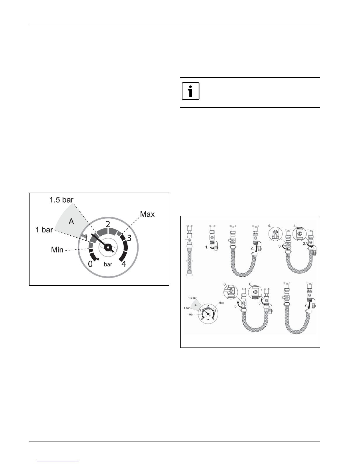
▶ Turn the hot water temperature control knob [1] to the
desired level between 1 and 8, this will be shown [3] on the
digital display.
▶ The tap symbol [2] will be displayed to confirm that the hot
water setting is being changed.
▶ The value is displayed during this process, press to
exit or after five seconds of inactivity the boiler display will
return to the default screen.
When reheating the heat store the controls will reclaim heat
from the boiler for the tank, this means that the pump will run
(and the blue light will be on) for some time after the burner has
turned off whilst heat reclaiming takes place.
WARNING: Care should be taken when using
slow running taps and showers, as in some
circumstances, the combination of low water
flow rate and high setting of the hot water
control thermostat can result in very hot water.
3.2.6 Eco mode
Domestic hot water Eco mode
Eco mode is an energy saving feature which alters the cycling
function of the burner for heating the heat store tank. In normal
operation the burner will fire more frequently between
demands in order to maintain a stored temperature close to the
hot water set point you have entered.
In Eco mode, the burner fires less frequently between demands
meaning that the heat store temperature is maintained at a
lower average level, but the tank set point remains the same.
By selecting Eco mode you will be using less energy as the tank
is allowed to cool a little more before reheating to the set point.
Selecting Eco mode
▶ Press and hold the Eco button [1] for at least four
seconds to enter the energy saving Eco mode, when Eco
mode is active, Eco will be displayed.
Fig. 3 Set DHW temperature
3.2.5 Domestic hot water (DHW)
The boiler is microprocessor controlled and at low DHW flow
rates (washing hands etc), the burner will not fire up
immediately when the tap is opened as the heat store will meet
the demand, but at high flow rates (filling a bath for example)
the burner will fire up to boost the heat store and meet the
demand.
If DHW is OFF on the programmer, the appliance wil l still supply
DHW using heat stored in the tank, but it will not reheat the
tank, therefore the amount of water available is limited but is
adequate for washing up, filling basins etc.
We recommend that DHW is timed off overnight and when the
hom e is unoccupied to save energy. The timer should be set for
at least half an hour before normal hot water demands are
expected to reheat the heat store.
Aqualand Green– 6720820498 (2016/07)
Fig. 4 Eco mode
Exit Eco mode
▶ To exit Eco mode, press and hold the Eco button for
eco
at least four seconds, Eco will disappear.
7
Page 8
Using your boiler
6 720 805 211-06.1TL
6 720 805 211-06.1TL
3.2.7 Frost protection
▶ The boiler has built in frost protection to protect the boiler,
the boiler must have power for this to operate.
▶ If you are leaving the property unoccupied during cold
weather, please leave your programmer on constant and
your room thermostat set to around 10 to 15°C.
▶ If the temperature within the boiler falls below 8°C the
pump will run to circulate water and prevent the system
freezing.
▶ If the temperature within the boiler falls below 4.5°C the
boiler will fire immediately, bringing the boiler temperature
up to 12°C to avoid the possibility of the system freezing.
▶ This process will be repeated until such time that the boiler
temperature does not drop below 4.5°C.
3.2.8 System pressure
This boiler is fitted to a sealed heating system that is prepressurised. Your installer will advise you of the minimum and
maximum pressure indicated on the pressure gauge.
▶ Check regularly that the pressure is maintained.
Filling loop
If the sealed system pressure within your system drops to
below 0.5 bar, as shown on the pressure gauge, you will need
to increase the pressure to ensure your boiler continues to run
without problems.
Your installer should have informed you where
to find the filling system and instructed you in
its use.
Once the external filling loop has been located, follow the
instructions for re-pressurising the system.
1. Unscrew blanking cap.
2. Attach the hose to the valves, screw on hand-tight.
3. Turn the handle/screwdriver slot through 90° to open
valves.
4. The handle/screwdriver slot will be in line with the valves.
5. When the pressure reaches between the 1 and 1.5 bar
marks (zone A), turn the handles/screwdriver slots back,
through 90°, to close the valves.
6. The handle/screwdriver slot will be at 90° to the valves.
7. Remove the hose and replace the blanking caps.
Fig. 5 System pressure gauge
Op ti mu m s yst em pr es sur e w he n y our bo il er is col d ( ar ea A) a nd
the pump is off. The indicated pressure will change as the pump
switches on, for more accurate readings check pressure when
the pump is not running.
▶ Contact your installer or maintenance engineer if a
permanent significant decrease or increase in pressure is
indicated on the pressure gauge.
8
Fig. 6 Filling link
Aqualand Green– 6720820498 (2016/07)
Page 9
4 Maintenance
reset
6720820043-05.1Wo
4.1 Troubleshooting
Maintenance
Boiler alert state
Should a fault develop with this boiler (or the system), the
boiler will enter into a fault condition:
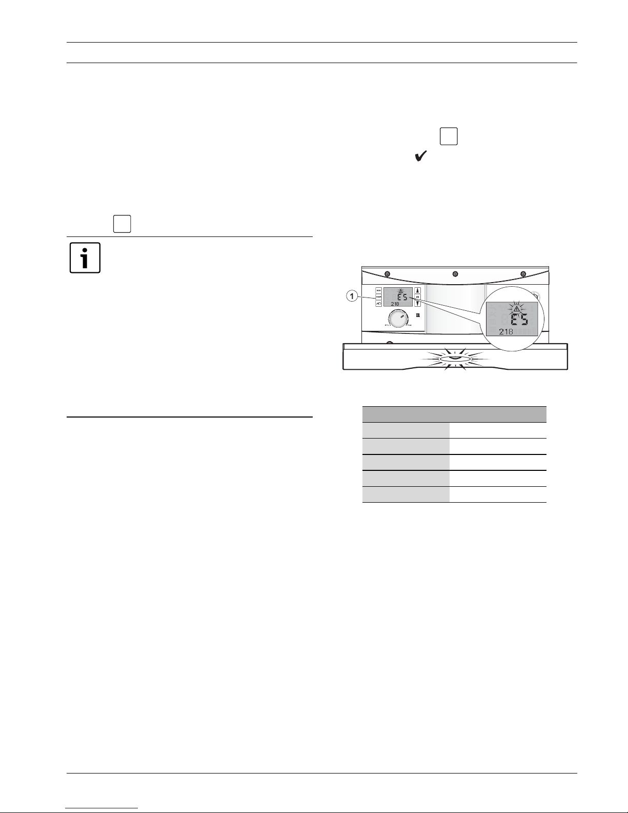
1. A fault condition is indicated by a flashing blue operation/
fault light and a triangular alert symbol on the display.
A flashing fault code is also displayed, see figure 7.
This type of fault can often be cleared by pressing the Reset
button .
Fault codes 9F and 855
▶ This is a burner lockout condition, press the
Reset button to restart the burner
▶ If the burner fails to fire and fault 9F 855 is
displayed again, check the oil supply to the
boiler
▶ If you try more than five times to reset the
boiler and fail, no more resets can be
attempted and the fault code 9F 856 will be
displayed, contact technical support via the
telephone number stated on the back of the
manual for assistance, quoting the fault
codes, contact details are on the back page.
Boiler reset
1. Press the Reset button on the fascia to clear the fault.
▶ Reset and a tick
symbol will be briefly displayed.
reset
▶ If the reset was successful the boiler will return to normal
operation.
▶ If the reset was not successful then the fault code will be
displayed again, and the blue operation/fault light will
continue to flash.
▶ Make a note of these fault codes, in the table below
as an example see figure 7, fault codes E5 and 218.
Fig. 7 Boiler reset
Flashing fault code Three figure number
e.g. E5 e.g. 218
Aqualand Green– 6720820498 (2016/07)
Boiler stops with no fault code
In most cases these fault conditions will clear automatically
when the associated fault clears e.g. waiting for an area of the
boiler to cool down.
If the boiler fails to automatically reset itself after a period of
30mins, contact technical support via the telephone number
stated on the back of the manual for assistance, quoting the
fault codes, contact details are on the back page.
9
Page 10
Maintenance
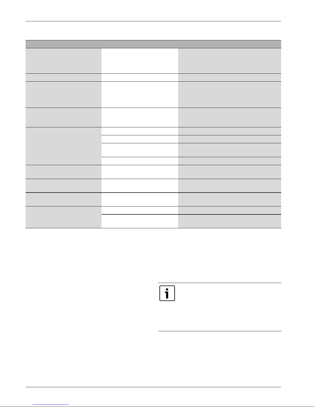
4.2 Fault finding
Problem Cause Remedy
Boiler stops working, blue light and
Internal error
warning triangle flashing and fault
code displayed
Boiler stops with no fault codes Possible overheat Wait 30 minutes for boiler to cool
Boiler stops working, blue light and
Burner lockout
warning triangle flashing and fault
codes 9F 855 are displayed
Fault codes 9F 856 More than 5 attempts at a reset
during Burner lockout fault 9F 855,
no more reset attempts can be made.
Desired room temperature is not
reached
TRV(s) set too low Increase thermostatic radiator valve setting(s)
Room thermostat set too low
Temperature control for CH flow on
boiler set too low
Air trapped in heating system Bleed radiators and recharge heating system
Desired room temperature exceeded
Radiators are too hot Turn down TRV(s)/room stat
by large amount
Room temperature rises instead of
Clock is incorrectly set Check setting and correct
falling
No display or display unit does not
Momentary power failure Switch off boiler at master switch, wait 30 seconds
respond
Hot water temperature too low Hot water temperature set too low Check setting on the boiler
Hot water not in timed period on the
programmer
Press the Reset button and the boiler should
restart, if not, contact technical support for
assistance, via the telephone number stated on the
back of the manual, quoting the fault codes.
Press the Reset button to restart the burner.
If the burner fails to fire and fault 9F 855 is
displayed again, check that there is enough oil in
the tank.
Contact technical support via the telephone
number stated on the back of the manual for
assistance, quoting the fault codes.
Increase room thermostat setting
Increase CH flow temperature control setting
then switch on again
Check programmer settings
Refer to your programmer manual
4.3 Maintaining your boiler
Your new boiler represents a long t erm in vest men t in a rel iabl e,
high quality product.
In order to realise its maximum working life and to ensure it
continues to operate at peak efficiency and performance, it is
essential that servicing and maintenance checks are performed
at least once a year by an competent registered engineer.
Maintenance tips
Regularly check the oil level in the tank. Running the tank empty
or low can lead to damage to the burner.
Do not obstruct the flue outlet or the air inlet.
Use in hard water areas
In exceptionally hard water areas a device to prevent scale
formation may be fitted. Installation of a scale inhibitor
as sem bl y sh oul d be in a ccor dan ce wit h th e re qui re men ts o f th e
local water company. An isolating valve should be fitted to
allow for servicing.
4.4 Servicing
You must have the boiler regularly serviced by a competent,
qualified registered engineer using approved spares, to help
maintain the economy, safety and reliability of the boiler.
The boiler should be serviced once each year after installation
unless the installation conditions and usage demand more
frequent services.
The service engineer must complete the Service
Record after each service.
The Service Record will be required in the event
of any warranty work.
The Service Record is at the back of the
Installation, Commissioning and Servicing
Instructions.
10
Aqualand Green– 6720820498 (2016/07)
Page 11
5 General information
6 720 805 211-08.1TL
General information
5.1 Ventilation information
Boiler location
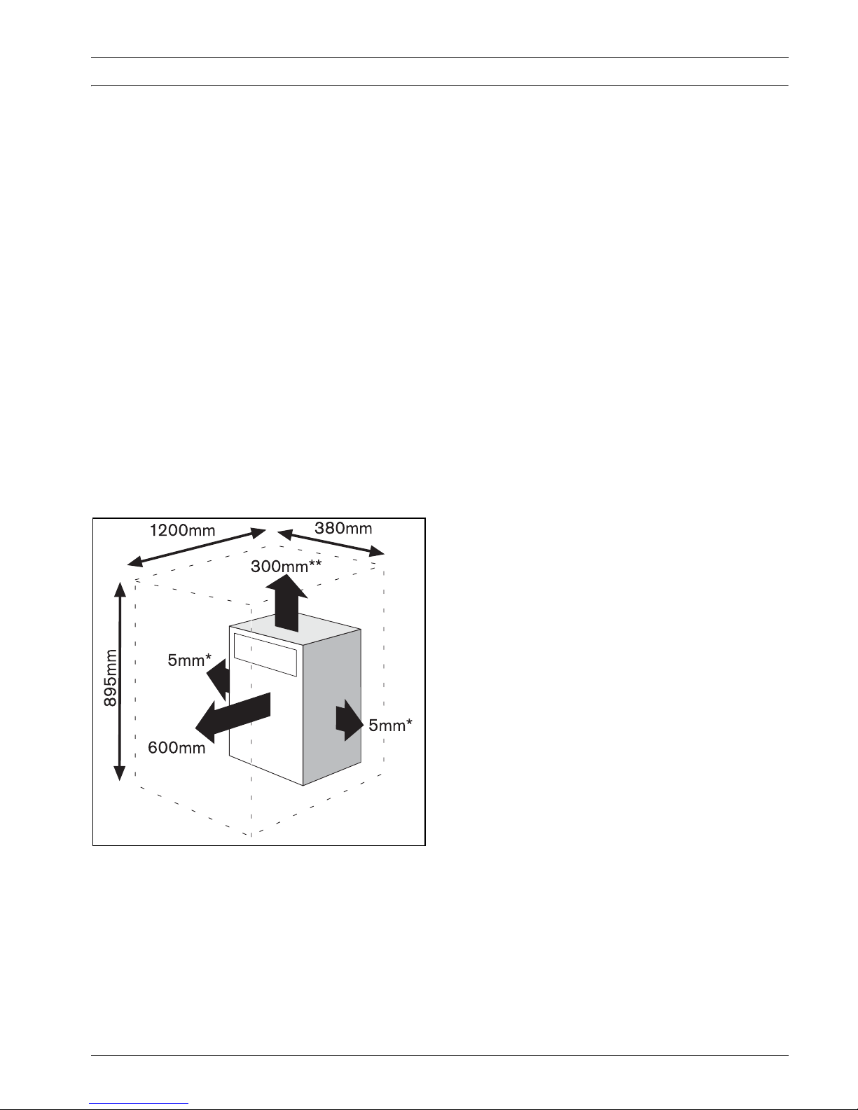
**The boiler can be installed under a work top as long as:
▶ The work top above the boiler is easily removable for
maintenance.
▶ There is at least 10mm clearance above the boiler.
▶ The front of the boiler is not enclosed.
Ventilation
Air vents must be functional at all times and the air supply must
not be restricted or contaminated.
The boiler clearances must meet the minimum shown below for
servicing and venting purposes.
* If this clearance is less than 75mm the flue 'knock-out' panel
sections must be removed to improve air circulation and
cooling.
Do not place clothes or objects to hinder the air circulation
required by the boiler.
Servicing clearances
5.2 General notes
To get the best from your boiler. please read these instructions
carefully.
Central heating systems
During the first few hours of operation of the central heating
system, check that all radiators are being heated at an even
rate. If the top of a radiator is at a lower temperature than the
bottom, then the radiator should be vented by releasing air
through the venting screw at the top of the radiator. Ask your
installer to show you how this is done. Repeated venting will
reduce the quantity of water in the system and this must be
replenished for safe and satisfactory operation of the boiler.
When excessive venting or water leaks are found in the system
you must contact a service engineer to inspect the installation
and rectify any fault.
Only use additives compatible with the boiler and system. Use
of incompatible additives can cause damage and will invalidate
the boiler guarantee.
Condensate drain
This is a condensing boiler and the terminal will, at times give
out a plume of water vapour. This is quite normal.
The boiler also produces quantities of condensate which is
discharged regularly via a pipe to drain. This pipe must not be
blocked or altered in any way.
Fig. 8 Clearances
Open flue boilers require an adequate supply of fresh air which
must be delivered to the boiler for combustion purposes
through a permanent inlet, into the area where the boiler is
situated.
If a cupboard or compartment is to be used for storage or airing
is built around the boiler, after installation, there must be a
non-combustible partition around the boiler. Refer to the
installation manual for minimum vent sizes.
Clearances - Service
Your installer will have provided adequate space around the
boiler for safety and servicing access.
Do not restrict this space with the addition of cupboards,
shelves etc. next to the boiler.
Room thermostat
A room temperature controller should be fitted to control the
central heating. Refer to instructions supplied with the
thermostat for information on siting and setting.
Thermostatic radiator valves
It is recommended that this type of valve is fitted to all but one
of the radiators (or at least those in the sleeping
accommodation). The remaining radiator, which must be
where the room thermostat is located, should be uncontrolled
and must be left open.
Oil supply
This appliance is for use with Heating Oil to EN590:2013 only.
Running the oil tank empty or low may result in damage to the
burner.
Aqualand Green– 6720820498 (2016/07)
11
Page 12
Energy saving
6 Energy saving
6.1 Tips on energy saving
Room thermostats
Reducing the setting of the room thermostat by 1°C can reduce
fuel consumption by up to 10%.
New control systems
Upgrade your heating control system with the latest equipment
available. The minimum recommended level of control for a
heating system is a programmer, interlocking room thermostat
and thermostatic radiator valves.
Radiators
More often than not radiators will be sited underneath a
window, so the warm air from the radiator heats the colder air
from the window.
The performance of the radiator will be affected if the curtains
are allowed to drape over the radiator or shelves are fitted
above it.
The positioning of furniture and tables in front of the radiator
should also be avoided.
It is advisable to manually adjust all radiator valves every 2-3
months to prevent them from sticking. It is also important that
the plastic tops of all valves are always in position and not
cracked or damaged to help prevent accidents. Care should be
taken when vacuum cleaning carpets to avoid damage to valves
and pipework.
The heating system and the outputs of the radiators have been
carefully selected by your installer. The temperature
obtainable in any given room is dependent on all radiators
being operated at the same time. If you decide to turn off
radiators in unused rooms, spare bedrooms etc., you may
experience slightly lower room temperatures in rooms ad jacent
to unheated rooms.
Roof insulation
Around 30% of the heat loss from a property is through the
roof. Replace any old insulation with new insulation.
Window frames
Single glazed windows, particularly those with steel frames,
can lose a great deal of heat.
Consideration should be given to replacement with PVCu or
wooden framed double glazed units.
Curtains
Lined curtains, or heavier full length curtains can provide
excellent insulation. However, always ensure that the curtains
do not drape over radiators.
Draughts
Try to ensure that draughts around doors, windows, letter
boxes and keyholes etc., are reduced by using a suitable
draught excluder.
WARNING:
▶ Do not block or seal any air vents that are
installed to ensure the central heating
boiler (or other appliance) operate safely.
Heating economically
The boiler is designed to provide a high level of comfort while
keeping oil consumption and the resulting env ironmental effect
as low as possible.
The central heating control on the boiler should be set as low as
possible while still maintaining a comfortable room
temperature.
The temperature of each room can be set individually using the
thermostatic radiator valves (except the primary room with the
room thermostat).
12
Aqualand Green– 6720820498 (2016/07)
Page 13
7Guarantee
1
6720820043-10.1Wo
7.1 Fault or breakdown
This boiler is supported by the Bosch Group.
Specialist Bosch Group Service Engineers are available to
attend in the unlikely event that a breakdown occurs on this
boiler.
General checks before calling a Service engineer
1. Oil level in the tank - is there enough oil in the tank?
2. Power to the boiler - is there electrical power?
3. All control settings - are the controls to provide heat or hot
water at this time?
Please read this guide carefully to gain a good understanding of
the operation of your boiler. In the case of a suspected fault,
refer to the fault finding section of this guide.
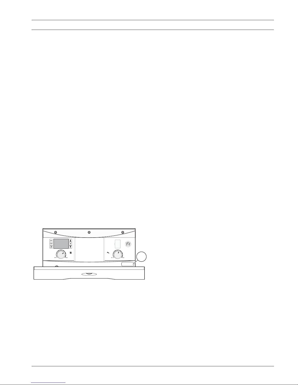
Boiler serial number label
The serial number label [1] can be found on the right hand side
of the control panel.
To access the serial number label, pull the control panel drawer
forward.
The serial number label contains the:
• serial number
•model name and output
• QR code containing the boiler serial number
(You can record this information in the table in General
Information, chapter 2 of this manual.)
Guarantee
Fig. 9 Serial number label location
Aqualand Green– 6720820498 (2016/07)
13
Page 14

Notes
14 Aqualand Green– 6720820498 (2016/07)
Page 15

Notes
15Aqualand Green– 6720820498 (2016/07)
Page 16
SER VIÇO PÓS-VENDA CHAMADA LOCAL
Bosch Termotecnologia, S.A. - Sede: Av. Infante D. Henrique, Lotes 2E e 3E - 1800-220 Lisboa | Portugal
Capital social: 2 500 000 EUR • NIPC: PT 500 666 474 • CRC: Aveiro
www.vulcano.pt
VULCANO
Departamento Comercial
Av. Infante D. Henrique, lotes 2E e 3E
1800-220 Lisboa
tel. 218 500 300 fax 218 500 301
[email protected]
Instalações Fabris
E.N. 16 - Km 3,7 Aveiro
3800-533 Cacia
 Loading...