

Page 1
SERVICE MANUAL
VSX BOILER BASE SERIES
CONVECTION STEAMERS
(GAS, ELECTRIC, DIRECT AND REGENERATED)
VSX24G ML-52163 VSX24D ML-52827
VSX36G ML-52360 VSX36D ML-52830
VSX42GT ML-52376 VSX42DT ML-52834
VSX24E ML-52164 VSX36R ML-52831
VSX36E ML-52829 VSX42RT ML-52835
VSX42ET ML-52833
VSX24G SHOWN
This Manual is prepared for the use of trained Vulcan Service
Technicians and should not be used by those not properly
qu alif ied. If yo u have attend ed a Vulcan Service School for this
product, you may be qualified to perform all the procedures
described in this man ual.
Thi s manu al i s no t i nten ded to be al l en comp assi ng . I f you have
not atte nded a Vulca n Servic e School f or this produc t, you should
read, in its entirety, the repair procedure you wish to perform to
determine if you have the necessary tools, instruments and skills
required to perform the procedure. Procedures for which you do
not have th e n ecessary too ls, in strument s and skills should be
performed b y a trained Vu lcan Service Technician.
Reproduction or other use of this Manual, without the express
written consent of Vulcan, is prohibited.
- NOTICE -
A product of VULCAN-HART LO UISVILLE, KY 40201-0696
Form 24627 ( 12/98)
Page 2

VSX SERIES STEAMERS
TABLE OF CONTENTS
GENERAL............................................................................. 4
Introduction ........................................................................ 4
Compartment Pan Capacity ........................................................ 4
Model Designations .............................................................. 4
Specifications ...................................................................... 5
Gas Steamers .................................................................. 5
Electric Steamers................................................................ 5
Steam Supply ................................................................... 5
Water Supply ................................................................... 6
Tools ............................................................................. 6
Water Conditi oning .................................................................. 6
STEAMER OPERATION.................................................................. 7
Cabinet Base Boilers ................................................................. 7
Gas Powered Steam Boiler ........................................................ 7
Electrically Powered Steam Boiler ................................................... 8
Direct Steam Powered Cooker ...................................................... 8
Regenerated Steam Powered Boiler .................................................. 8
Boiler Blowdown and Steamer Shut off ................................................... 8
Cooking Compartment Controls......................................................... 9
COMPONENT FUNCTION AND LO CA TION ................................................. 10
Cabinet Base Boiler Controls .......................................................... 10
Cooking Compartment Controls........................................................ 14
SERVICE PRO CE DURE S ................................................................ 15
Cabinet Bases ..................................................................... 15
Boiler ........................................................................ 15
Descaler...................................................................... 16
Water Level Controls
(Low Level Cut-Off and Different ial) ............................................. 16
Water Level Gauge Assembly ..................................................... 17
Pressure Switches (Gas and Electric Models) .......................................... 17
High Limit Thermostat ........................................................... 18
Removing The Boiler Assembly .................................................... 18
Fill and Cold W ater Solenoid Valv es ................................................ 18
Water Not Being Supplied to Boiler ................................................. 19
Blowdown Solenoid Valve Does Not Drain ............................................ 19
Steamer A chieves Pressure Slower Than Normal ...................................... 20
Inlet Water Strainer ............................................................. 21
Gas Models ................................................................... 21
Pilot , Thermoc ouple or Main Burner s ............................................ 21
Automatic Ignition Systems.................................................... 22
Gas Combination Control Valve Replacement ..................................... 23
Manifold Pressure Adjustment ................................................. 23
Electric Models ................................................................. 24
Magnetic Cont actor .......................................................... 24
Heating Element............................................................ 24
Direct Steam Models ............................................................ 26
Regenerated Steam Models (Steam Coil) ............................................. 26
COOKING COMPARTMENT.......................................................... 26
Controls ...................................................................... 26
Steam Supply Solenoid .......................................................... 26
Water Accumulating in Compartment................................................ 27
Cooking Cycl e Cannot Be Activated ................................................. 27
Intake Shut-Off Valve Adjustment (Steam Flow)........................................ 27
Door......................................................................... 27
Page 2 of 80
Page 3

VSX SERIES STEAMERS
ELECTRICAL OPERATION .............................................................. 30
Water Level Controls................................................................ 30
Solid State -
Low level Cut-Off & Differential Control .......................................... 30
Electro Mechanical - Low level Cut-Off & Differential Contr ol .............................. 32
Sequence of O per ation .............................................................. 34
Gas Models ................................................................... 34
Electric Models ................................................................. 37
Schematics, Gas Steamers, Boiler Controls
VSX24G, 36G and 42GT ......................................................... 41
Manual Igni tion, St andar d Controls .............................................. 41
Electronic Ignition, Standar d Controls ............................................ 42
Manual Igni tion, CSD-1 Code Cont r ols ........................................... 43
Electronic Ignit ion, CSD-1 Code Controls ......................................... 44
Wiring Diagrams, Gas Steamers, Boil er Controls
VSX24G, 36G AND 42GT ........................................................ 46
Manual Igni tion, St andar d Controls .............................................. 46
Electronic Ignition, Standar d Controls ............................................ 48
Manual Igni tion, CSD-1 Code Cont r ols ........................................... 50
Electronic Ignit ion, CSD-1 Code Controls ......................................... 52
Schematics, Electric Steamers, Boiler Controls
VSX24E, 36E AND 42ET ......................................................... 54
Auto Blowdown, Standard Controls .............................................. 54
Auto Blowdown, Cal-Code Controls .............................................. 55
Auto Blowdown, Standard Controls .............................................. 56
Auto Blowdown, Cal-Code Controls .............................................. 57
Wiring Diagrams, Elec tric Steamers, Boiler Controls
VSX24E, 36E AND 42ET ......................................................... 58
Auto Blowdown, Standard Controls .............................................. 58
Auto Blowdown, Cal-Code Controls .............................................. 60
Auto Blowdown, Standard Controls .............................................. 62
Auto Blowdown, Step Down Transformer, S tandard Controls .......................... 64
Auto Blowdown, Step Down Transformer, Cal-Code Controls (2 contactors) ............... 66
Auto Blowdown, Step Down Transformer, Cal-Code Controls (4 contactors) ............... 68
Wiring Diagr ams, Electric Heater Circuits
VSX24E, 36E AND 42ET ......................................................... 70
Schematic, Direct Steamers, Cabinet Base
VSX24D, 36D and 42DT .......................................................... 73
Wiring Diagram, Direct Steamers, Cabinet Base
VSX24D, 36D and 42DT .......................................................... 73
Wiring Diagrams, Regenerated Steamers, Boi ler Controls
VSX36R and 42RT (Older Models) .................................................. 74
Schematic All Models - Compart ment Controls ............................................ 76
Wiring Diagram, All Models - Compartment Controls ........................................ 77
TROUBLESHOOTING .................................................................. 78
© VULCAN 1998
Page 3 of 80
Page 4
VSX SERIES STEAMERS - GENERAL
GENERAL
INTRODUCTION
General
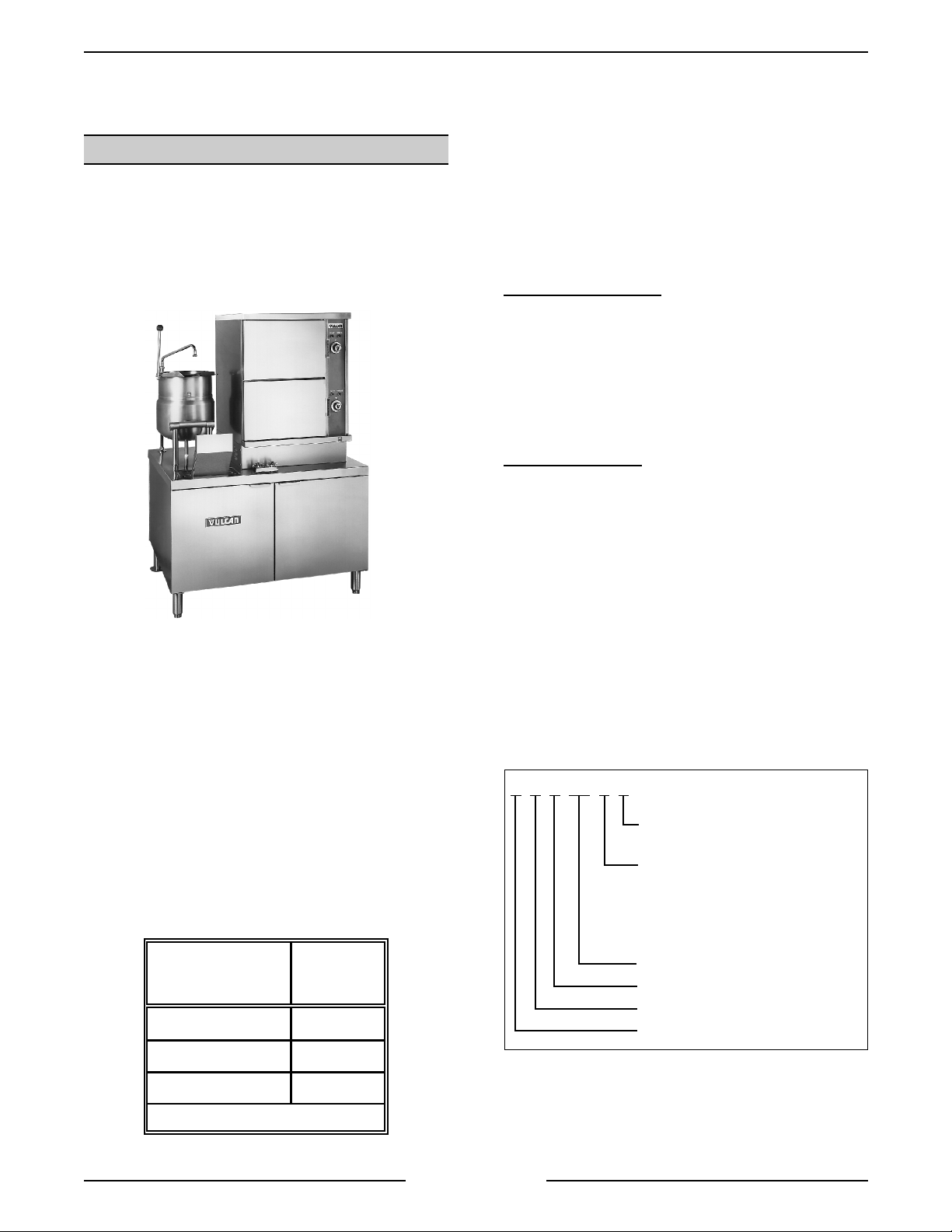
This manual is applic able for all models listed on the
cover page. A conv ection steam er on a 42 inch
base with a til ting kettle is pictur ed below for
reference.
VSX42RT SHOWN
Steam Cooking
Pressure-less steamers offer an ef ficient way to
produce many foods in smal l portions or l ar ger
batches. Pressure-less, convecti on steam cooking
will steam cook fresh foods or will steam defrost and
cook froz en foods providing the maxi mum color,
flavor and nutr itional value with the least
expendit ur e of energy and l abor . The pressure-less
steaming compartment allows the operator to open
and close the door, anyti me during a cooking cycle.
The steam supply will shut off when the door is
opened, then re-start when the door is closed.
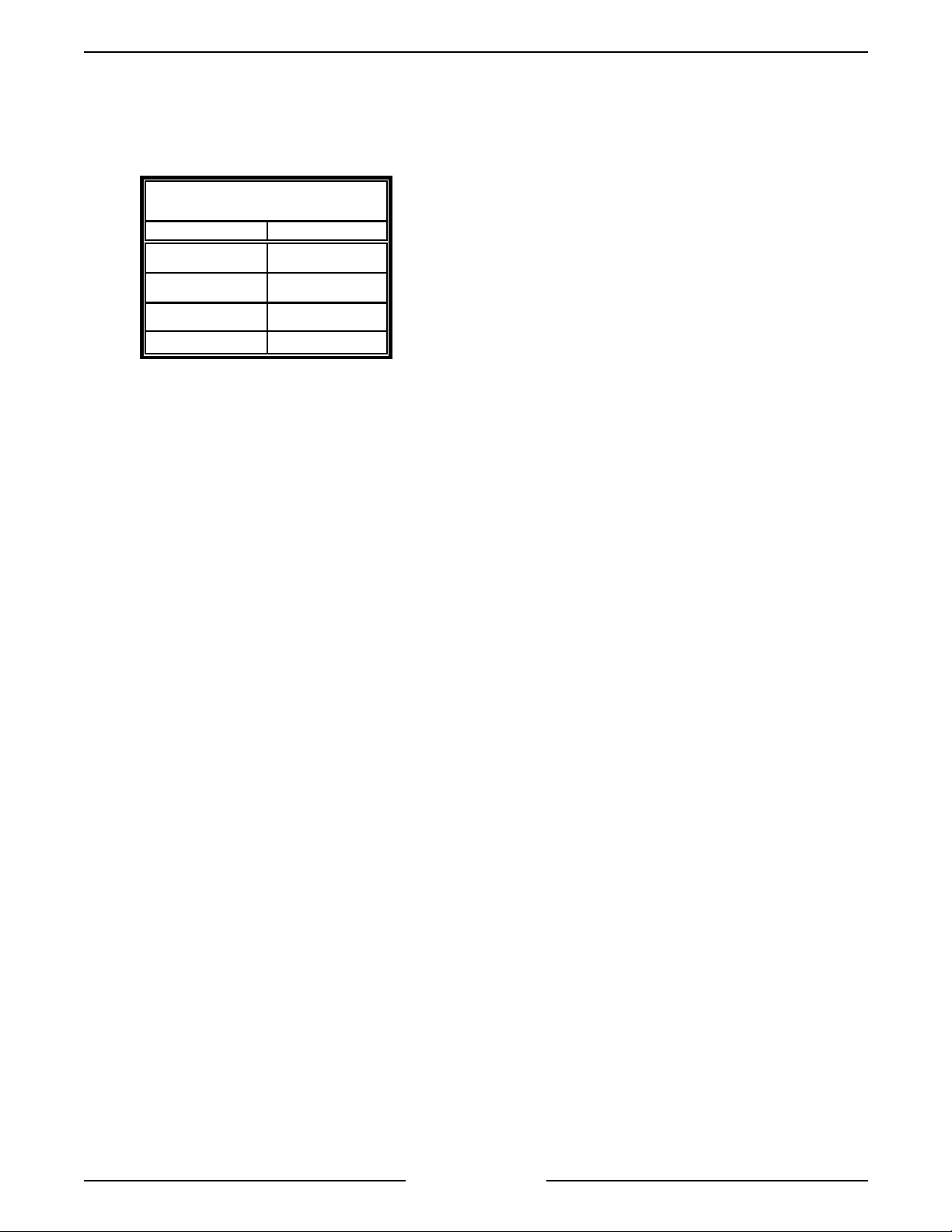
Compartment P an Capacity
NUMBER OF
PANS PER
COMPARTMENT
24.0
DEPTH
(INCHES)
Boiler Code Descriptio ns
Vulcan-Hart incorporates redundant c ontrols in
compliance with California Code (Cal-Code) and
CSD-1 as an option on steam equipment when
required by stat e and/or local building code
requirements. Descriptions of the codes are listed
below.
Cal-Code Construct ion
electrical safety circuits that, i f tri pped, must
manually be reset after the condit ion causing the trip
subsides. These controls consist of - (1) dual
function water level cycling and low level cut off
control and ( 1) si ngle funct ion low water level cut- off
control ( A ux - LLCO) and a hi gh pr essure rel ief
switch in conj unc tion with a m ec hanical pressure
relief valve.
CSD-1 Constructi on
electrical safety circuits that, i f tri pped, must
manually be reset after the condit ion causing the trip
subsides. These controls consist of - (1) dual
function water level cycling and low level cut off
control and ( 1) si ngle funct ion low water level cut-off
control ( LLCO) and a high pressure reli ef switch in
conjunction with a mechanical pressure relief valve.
Additi onally, both circui ts have individual indicator
lights that will illum inate for a visual verification of
the shutdown mode.
Cal-Code and CSD-1 constr uc tion both requi r e
operator intervention in the event of a shutdown.
CSD-1 is mor e informative by using indicator lights
to show which safety system was shutdown.
Model Desi gnations
S X XX X X
V
- Redundant controls in the
- Redundant controls in the
T - Tilting kettle (24 qt.) found
on 42" wide cabinet base onl y .
Heating System:
G - Gas
E - Electric
D - Direct
R - Regenerated
Cabinet Base Width ( inches)
Pressure-less
Steamer
Vulcan
32.5
61.0
Pan Size 12" x 20"
Page 4 of 80
Page 5
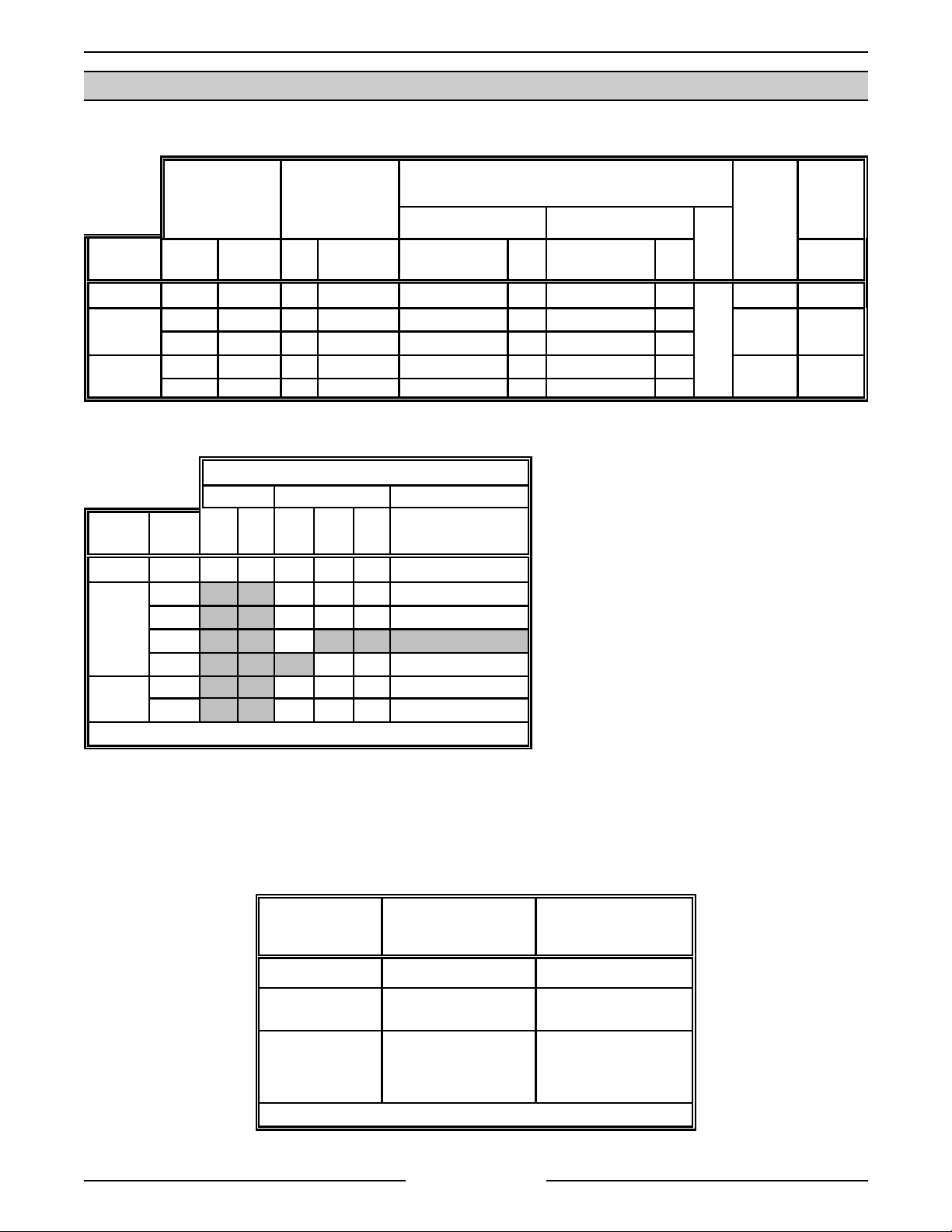
Gas Steamers
VSX SERIES STEAMERS - GENERAL
SPECIFICATIONS
INPUT
(BTU/HR)
MODEL NAT. PROP. NAT. PROP. RECOMMEND MIN RECOMMEND MIN
VSX24G 200,000 200,000 4.0 10.0 7.0 5.0 11.0 11.0
VSX36G
VSX42GT
200,000 200,000 4.0 10.0 7.0 5.0 11.0 11.0
240,000 240,000 4.0 10.0 7.0 5.0 11.0 11.0
200,000 200,000 4.0 10.0 7.0 5.0 11.0 11.0
240,000 240,000 4.0 10.0 7.0 5.0 11.0 11.0
MANIFOLD
PRESSURE
(INCHES W.C.)
NATURAL PROPANE
LINE PRESSURE
(INCHES W.C.)
Electric Steamers
AMPERAGE
1 PHASE 3 PHASE 3 PHASE - 4 WIRE
MODEL
VSX24E 24* 116 100 67 58 29 34
VSX36E
VSX42ET
*std
TOTAL
208V 240V 208V 240V 480V 220/380V & 240/415V
KW
24* 67 58 29 34
36 100 87 44 50
42 117
48 116 58 67
24* 67 58 29 34
36 100 87 44 50
MAX
14.0
LOAD
(WATTS)
360 3.0
360 3.0
360 3.0
AMPS
(MAX)
120V
60HZ
Steam Supply
Dry steam must be prov ided to the steam er . If t he steam is heavy with condensate, a Ball Fl oat Trap must be
used in the line and plumbed in before the pr essure reducing valve. To ensure rapid heat up of heavy c old loads,
the steam supply line must be si z ed to maint ain pressure as outlined bel ow.
DIRECT STEAM
STEAMERS
(POTABLE)
Supply Pressure 15 psi (max.) 15 psi (max.)
Flow Rate 100 lb. per hour total
Pre ssure Reducing
Valve Output
*Potable stea m is no t required for regenerated models but could be used.
(min.)
10 psi (furnished) set accordingly for good
REGENERA TED STEAM
STEAMERS
(*NON-POTABLE)
125 lb. per hour total
(min.)
steam gene ration but no
higher than 15 psi.
(furnished)
Page 5 of 80
Page 6
VSX SERIES STEAMERS - OPERATION
Water Supply
Supply pressure should be 20-80 psig
In line strainer f or suppl y line (Not Supplied)
Supply connection cold
Total dissolved solids (TDS)* less than 60 ppm
Total alkalinity less than 20 ppm
Silica less than 13 ppm
Chloride less than 30 ppm
PH fact or 7 to 8
(*17.1 ppm = 1 grain of har dness)
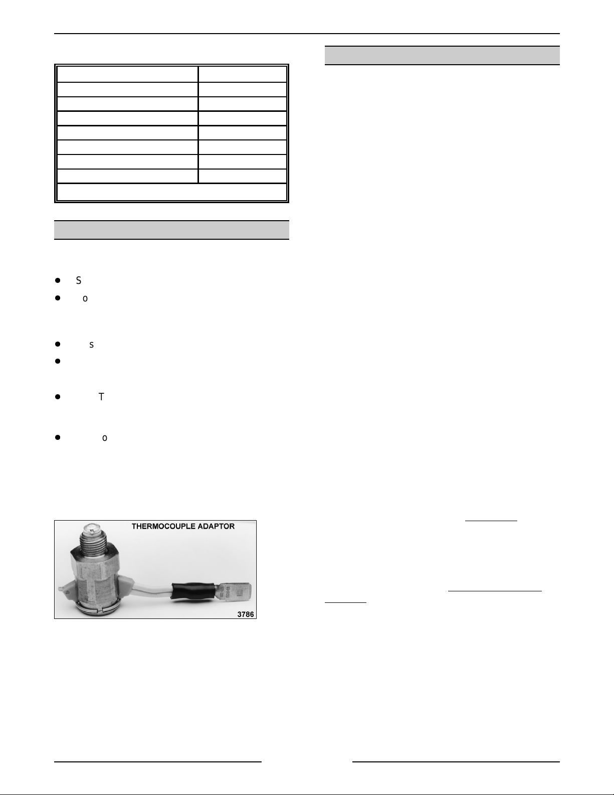
TOOLS
Standard
Standard set of hand tools.
Volt-Ohm-Meter (VOM) with AC current tester.
(Any quality VOM wit h a sensit ivity of at least
20,000 ohms per volt c an be used)
Gas leak checking equipment.
Gas Pressure Manometer
Special
CLR Treatm ent Kit - Used to remov e
Calcium/Lime/Rust fr om a boiler ( Contact
Vulcan Authorized Service Cent er s ).
Adaptor to test thermocouple closed circuit
voltages (DC) on gas models with manual
ignition (purchase locally).
NOTE:
An exam ple of one adaptor type is pict ur ed
below.
Adaptors v ary between manuf ac turers.
WATER CONDITIONING
Furnishing the boiler wit h soft water to reduce scale
formation is important. Scale formation will reduce
steam output, cause premature c omponent f ailure,
and shorten equipm ent life. Most water supplies
contain scal e pr oduc ing miner als such as Calcium
and Magnesium. A s steam is generated, the
minerals remain and dissolve into the water. As the
concentration of these minerals inc r eases past a
certain point, they pr ec ipitate from the water and
coat the inside of the boiler, heating elements,
thermostat bulbs and water level probes. Because of
the high temperature of these surfaces, the
precipitated minerals bake onto them and become
very difficult to remove.
This causes several problems:
1. Reduce the heat transfer efficiency of the
heating system .
2. Cause premature failure of E lectric heaters.
3. Water l evel pr obes will give false readings.
4. Thermostat bulbs will sense temperature
incorrectly.
These problem s are common to any manufacturer's
steamer regardless of design, but t hey c an all be
prevented by furnishing the boiler with soft water.
Vulcan recommends the water cont ain less than
60ppm of “ total dissolved soli ds” (TDS) and hav e a
PH fact or between 7 to 8. These water properties
can be achieved by using a properly maintained
water softener.
Other chemical pr oper ties in water supplies can also
affect good steam generation and vary fr om within
each state and locality.
The water level probes in the boiler use ions i n the
water to detect the water level.
demineralized or de-ionized water since it is "non
conductive" and the water level can not be detect ed.
Do not use
fully
NOTE:
remove mi nerals from the water.
Vulcan recommends that a local water treatment
specialist be consulted before t he installat ion of any
steam generating equipment.
Steamers that operate over a long peri od of time
without the benefit of a water softener, which have
developed a heavy scale build up, should be
cleaned bef or e using a water softener.
Page 6 of 80
The use of strainers, or filters will not
Page 7

VSX SERIES STEAMERS - OPERATION
STEAMER OPERATION
WARNING:
SERVICING THE STEAMER. THE COOKING COMPARTMENT CONTAINS LIVE STEAM. STAY CLEAR
WHEN OPENING EACH DOOR.
Ensure that all utility connections to the steamer
have been made and are turned on.
On model s that are Cal-Code/CS D- 1 equipped,
amber col ored lights for Hi pressure and low water
level will illuminate and stay on until the boiler is full
and the manual reset switch pressed.
Gas Powered Steam Boiler
1. Open the cabinet door and turn main power
THE STEAMER AND ITS PARTS ARE HOT. USE CARE WHEN OPERATING, CLEANING OR
On Models with Automatic Ignition
CABINET BASE BOILERS
switch ON. The red light will illuminate, water
will begin filling the boiler and the blowdown
solenoid valve will close. The boiler should fill,
in four to eleven minut es. Observe water l evel
gauge glass to verify that water is in boi ler and
that the l evel in the gauge glass is about hal f
full. Both valves on gauge glass assembly m ust
be open to fill the gauge. Older models
equipped with a manual “ball” type blowdown
valve must be closed for the boiler to fill. The
cycling pressure switch will maintain the proper
steam pressure in the boiler by cyc ling the
heating system on and off to generate steam
pressure.
On Models with Manual Ignition
A.
knob on the gas combination contr ol valve
has three positions (O n- P ilot-O ff) for
control of main burners and pilot. Turn
knob on gas combination valve to PILOT
then depress and light pilot burner with a
lit taper. Maintain knob in depressed
position for about 30 seconds and release.
Observe that pilot burner flame stays on. If
the flame should go out, wai t 5 minut es
before relighti ng.
- The
B.
The knob on the gas com bination cont r ol
valve has two positions (On-Off) for
control of main burners and pilot. For the
automatic ignition system t o work, the
knob must be set i n the ON position or gas
for the pilot and main burners will not flow.
Also, the ignition c ontrol module
ON/OFF/RESET switch must be in the ON
position to operate. Thi s switch is located
on the upper left side of the electrical
control box for the ignition control module.
A red light will illuminate when the switch
is in the ON posi tion. DO NO T ATTEMPT
TO MANUALLY LIGHT THE PILOT IN AN
AUTOMATIC TYPE IGNITION SYST EM.
After the main power switch is turned ON
and the ignition control modules RESET
switch is in the ON position, sparking will
begin three seconds lat er to light the
standing pilot. If the pilot light s, a si gnal is
sent back through the igniti on c able
indicat ing the presence of pilot flame and
sparking stops. If the water level i n the
boiler has reached the minimum level, the
burners will ignite and begin to heat t he
water in the boi ler. After approximately 15
minut es, st eam should be present f or
cooking product. Observe that the boi ler
pressure gauge indicates steam pressure
of 8-10 psi. If a pilot flame i s not
established immedi ately, sparki ng will
continue for 90 seconds. After that
duration, the ignition control module will
lock out and needs to be r eset to start the
pilot and burner lighting cycle again.
-
Turn knob on gas combination cont r ol
valv e to ON. If the water level in the boiler
has reached the minimum level, burners
will ignite and begin to heat the water in
the boiler . After approximately 15 minutes,
steam should be present for cooking
product. Observe that the boiler pressure
gauge indicat es steam pressure of 8-10
psi.
Page 7 of 80
Page 8

VSX SERIES STEAMERS - OPERATION
Electrically Powered Steam Boiler
Open the cabinet door and turn m ain power switch
ON. The red light will illuminate, water will begin
filling the boiler and the blowdown solenoid val ve
will close. The boiler should fill, in 4 to11 minutes.
Observe water level gauge glass to v er ify t hat water
is in boiler and that the level in the gauge gl ass is
about half full. Both valves on gauge glass
assembly m ust be open to fill the gauge. Older
models equipped wi th a manual “ball” type
blowdown valve must be closed for the boiler to fill.
If t he water level in the boiler has reached the
minimum level, the magnetic cont ac tors will close,
the heaters will energize and begin to heat the water
in the boiler. After approx imately 15 minutes, steam
should be present for c ook ing product. O bserve that
the boiler pressure gauge indicates steam pr essure
of 11-13 psi.
Direct Steam Powered Cooker
1. Open the cabinet door and turn main power
switch ON.
A. The red light on the switch will illuminate.
B. If steam pr essure is above the m inimum
setting on the cooking compar tment
pressure switch then the switch will close,
ready light will come ON and power to the
other controls will be supplied.
C. Observe that the steam pressure gauge in
the cabinet base, indicates 10-12 psi.
2. Steamer is ready t o c ook pr oduc t.
Regenerated Steam Powered Boiler
BOILER BLOWDOWN AND
STEAMER SHUT OF F
Turn the steamer off at least once daily and blow
down the boiler t o r emov e sedi ments, scalants and
lime build-up in the boil er . Always blowdown the
boiler when it is under maximum pressure and no
steam is bei ng used.
1.
Automatic blowdown.
A. Newer Models
and turn main power switch OFF. The
switches’ red light will go out, the
blowdown/drain solenoid valve will be deenergized and the boiler will begin to
drain. The cold water condenser solenoid
will continue to operat e, as needed, to
condense steam and to cool the water
going into the drain.
B. Older Models
and depress blowdown timer butt on.
Blowdown timer will operate for 4 minutes.
At the end of blowdown, turn fill switch to
ON and allow boi ler to f ill.
2.
Manual blowdown.
A. All Models
blowdown valve loc ated on the bottom
front of the cabi net base. After the boiler
has completely drained, c lose blowdown
valve and t ur n fill switch to ON and allow
boiler to fill.
- Open the cabi net door
- Turn power switch OFF
- Turn power switch OFF. Open
1. Open the cabinet door and turn main power
switch ON. The pilot light will illuminate, water
will begin filling the boiler and the blowdown
solenoid valve will close. Models equipped with
a manual “ball type” blowdown valve need to
be closed for the boiler to f ill. The boiler should
fill, in approximately 15 minutes. Observe
water level gauge glass to verify that water i s i n
boiler and t hat the level i n the gauge glass is
about half full.
Both valves on the gauge glass assembly must
be open to fill the gauge. When the water
reaches the minimum level, the steam solenoid
valve will open, allowing steam to enter the
steam coil in the heat exchanger tank and
begin heating the water. Af ter approxi mately 20
minut es, a sufficient amount of pressuriz ed
steam should be present for cooking pr oduc t.
Page 8 of 80
Page 9

VSX SERIES STEAMERS - OPERATION
COOKING COMPARTMENT
CONTROLS
When the steam pressure in the c ook ing
compartment manifold reaches approximately 3 psi ,
the cooking compartment pressure switch closes,
suppling power to the ot her c ontrols. The ready
lights will illuminate and after approximately one
minute, the steam pressure in the boiler will reach
the upper li mit of 10 psi. If the pressure drops below
approximately 3 psi , the pressure switch will open,
removing power f r om the cooki ng c ompartm ent
controls.
NOTE:
the ready light comes on, a loud clanki ng sound wil l
be heard (oil c anning) and the ready l ights will flash
for several seconds. This condition is caused by the
manifold pressure being on t he “fringe” of the
pressure switch set point. When a cook t imer i s set,
the compartment steam solenoid valve opens
causing the manifold steam pressure to drop,
slightly below the pressure switch set point. At the
same time, steam pressure is still increasing in the
boiler. This opposing condit ion causes a pressure
“bounce” to occur but after the steam pressure
passes approximat ely 4 psi this condition subsides.
Under normal steam cycling pressures, this
conditi on will not be seen.
If a cook ing timer is set immediat ely aft er
5. When timer knobs reach "0", buz z ers will
sound, steam generation will cease, cooking
lights will go off and ready lights will come on.
To silence buz z er s, turn timer knobs to off
position.
6. During a cooking cycle, the heat ing system will
cycle on and off as necessary to maintain
steam pressure in the boiler.
NOTE:
occur due to the r egulated constant steam supplied
from the building. Steam will come on for cooking
when a cook tim er is set and go off at the end of
that time.
7. Turn power switch off t o r emov e power from
8. Blowdown boiler. See “BOILER BLOWDOWN
On direct st eam units, no steam cycling will
the steamer and the red light will go out.
AND STEAMER SHUT-OFF” under
“STEAMER OPERATION”.
1. With both tim er knobs at the off position, open
the compartment doors and observe that no
steam has entered the c ook ing compart ments,
then close the doors.
2. Set both tim er knobs at 2 minut es. The ready
lights will go off, the cooking lights will come
on, and steam will begin to enter the
compartments.
3. After one minute, open each door and observe
that steam has ceased to enter each
compartment, cook ing light s go back to ready,
and one minut e is remaining on each cook
timer.
4. Close doors and steam generation and cook
timing will resume. Observe the floor drain to
ensure that live steam from compart ments is
being cooled by cold water fr om the cold water
condenser solenoid valve.
Page 9 of 80
Page 10

VSX SERIES ST E A M E RS - COMPONENT FUNCTION AND LOCATION
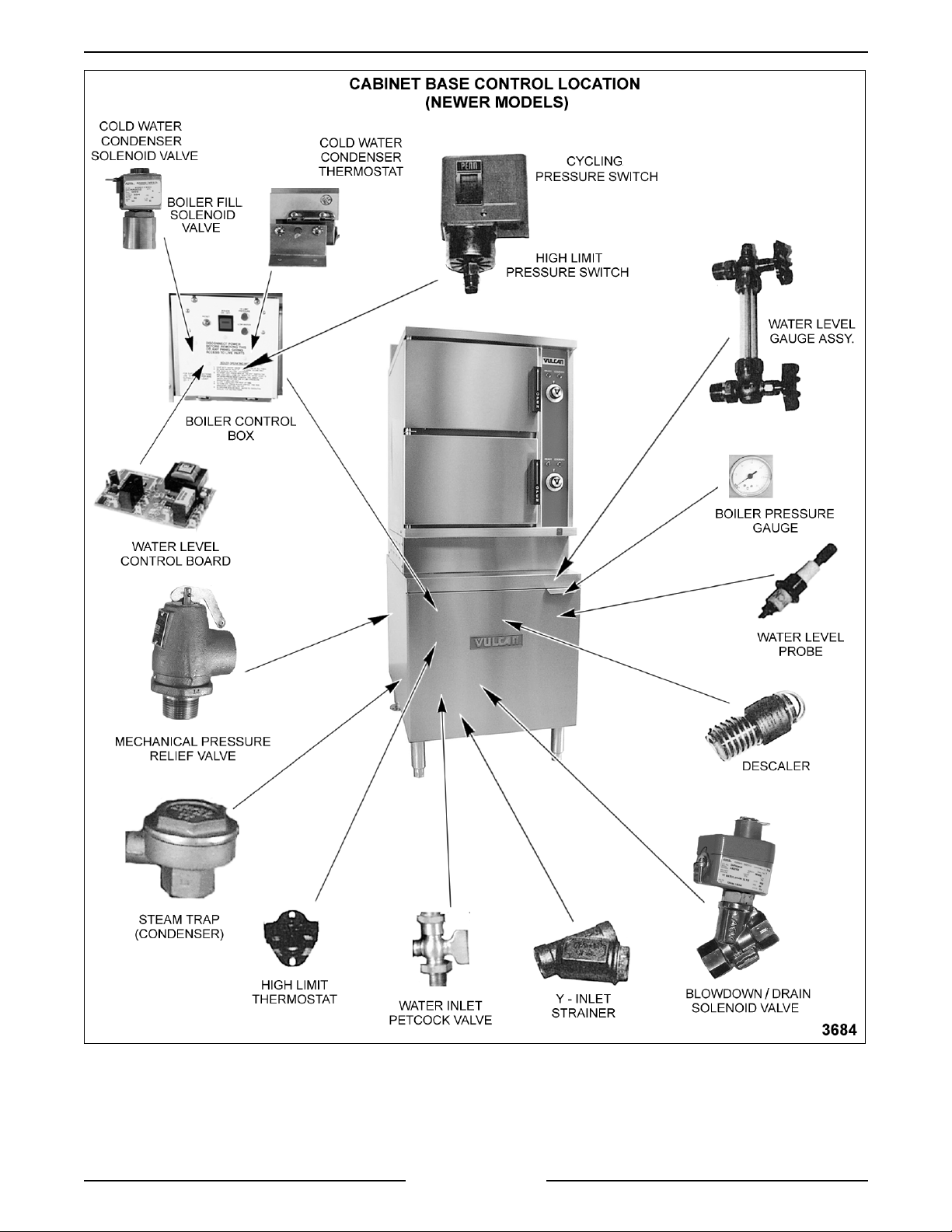
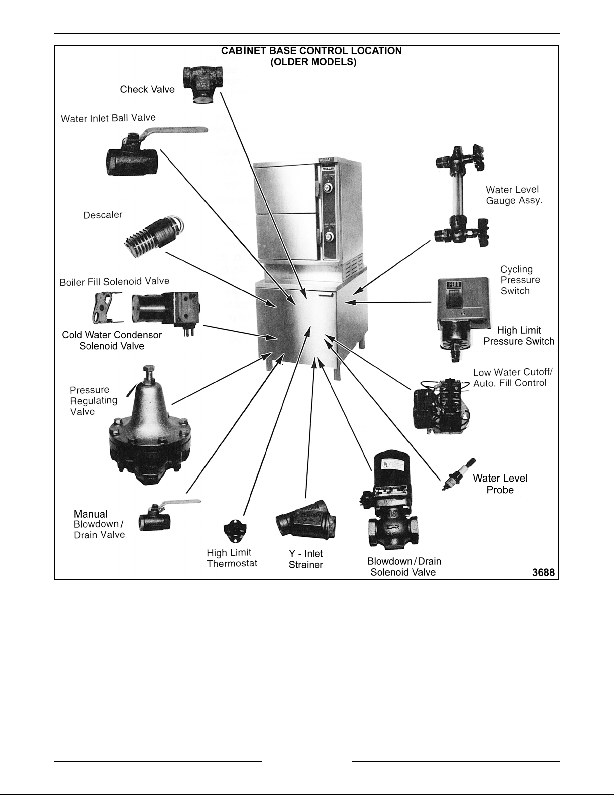
COMPONENT FUNCTION AND LOCATION
CABINET BASE BOILER
CONTROLS
WARNING
HOT. USE CARE WHEN OPERATING, CLEANING
OR SERVICING THE STEAMER. THE COOKING
COMPARTMENTS CONTAIN LIVE STEAM. STAY
CLEAR WHEN OPENING EACH DOOR.
Water Level Gauge Assembly
confi r mation that water level is bei ng maintained in
the boiler during operati on. The correct water level
is a point one-half of the height of the glass. The
manual valves at the top and bottom of this
assembly m ust be full y open and only closed if the
glass tube is damaged.
Observe that the water is clean and clear in the
glass tube. The appearance of ext r eme murkiness
in the water i ndicates inadequate water quality and
will cause failure of controls and the steamer.
War ranty does not cover mal functi on due to poor
water conditions. Blowdown and/or clean out t he
boiler as outlined in “BOILER BLOWDOWN AND
STEAMER SHUT-OFF” under “STEAMER
OPERATION” and “BOILER” under “SERVICE
PROCEDURES”.
Water Level Control and Level Sensing Probes
these controls al low water to enter the boiler to f ill
and maint ain the proper water l evel. They will also
shut off the heat source to the boiler i f the water
level drops too low.
The water level cont r ol works by using three
different probe lengths to monitor the water level.
The probes consist of a high level (HL), low level
(LL) and low water cut-off (LLCO). The level sensing
probes may easil y be r emov ed to inspect f or lime
build up. A s a rule, the condi tion of these devic es
will indicate the overall water condition of t he boiler.
Clean the probes if needed.
NOTE:
clogging will occur if a daily blowdown procedure is
not followed.
Boiler Fill Solenoid Valve
boiler when dem anded by the water level control to
maintain the correct water level in the boiler.
Cold Water Condenser Solenoid Valve
cold water flow into the boiler blowdown drain box to
condense steam and cool the hot water before its
discharge int o the drain.
: THE STEAMER AND ITS PARTS ARE
- permits visual
-
Controls m ay not function and serious
- admits water to the
- allows
Cycling P ressure Switch
between prescribed limit s by t ur ning the heat source
on and off.
High Limit Pressure Sw itch
design to the cyc ling pressure switch but used as a
high li mit. The pressure settings are at hi gher and
lower limits than the cycli ng pressure switch in order
to turn off the heat sourc e before the boi ler pressure
reaches its limit and automati c ally resets af ter the
pressure drops below the lower limit set point.
Blowdown/Drain Solenoid Valve
plumbed into the drai n pipe of the boiler. Newer
steamer models will automatically blowdown when
power is turned off by using a normally open
solenoid valve. Older models can have a solenoid
valve t hat is activated by depr essing a separate
blowdown timer button or have a manual “ball” type
valve. Daily boiler blowdown is essential to proper
operation and component life by removing sediment
and scalants that may be lodged in the chamber of
the boiler .
Strainers
to prevent foreign matt er from becoming lodged in
the fill or cold water condenser solenoid valves and
to keep unwanted parti c les out of the system. A "Y"
strainer should be inserted upstream of the fill
solenoid valve.
On model s using a direct steam suppl y , a strainer i s
used in the pressure regulating valve.
Power Switch
to the controls and the steam generat ing process is
started in the boiler. The power switch is located on
the front of the boiler contr ol box.
Water Inlet Valve
stop water fl ow to t he steamer when the steamer is
being serv iced. Newer models will have a sm all
Petcock type val ve whil e older model s will be a
“ball” type valve. This valve should remain open
during normal operati on.
High Limit Thermostat
shuts off the heat source if the boil er temperature
exceeds a specified limit . All standard models are
equipped with a surface high limit .
Descaler
boiler and is used to help control boiler surf ac e
scaling. Two descalers are used in each boiler.
Handhole Cover Assembly
removed, allows internal ex amination and cleaning
of boiler shell and its components if required.
- a strainer is used in the water inlet line
- when turned ON, power is suppli ed
- the water inlet v alve is used to
- hangs submerged in water i nsi de the
- control s boi ler pressure
- a switch of identical
- this valve is
- a protective device that
- when unbolted and
Page 10 of 80
Page 11
VSX SERIES ST E A M E RS - COMPONENT FUNCTION AND LOCATION
Pressure Gaug e
- indicates boiler steam pressure.
Normal operating pressures are listed below.
STEAMER
TYPE
Gas 8 -10
Electric 11 - 13
Direct 10 - 12
Regenerated 10 - 12
- drains steam c ondensate and water from
Drain
PSI
cooking compartments and boiler.
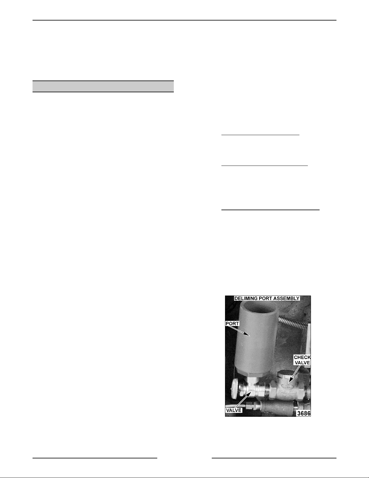
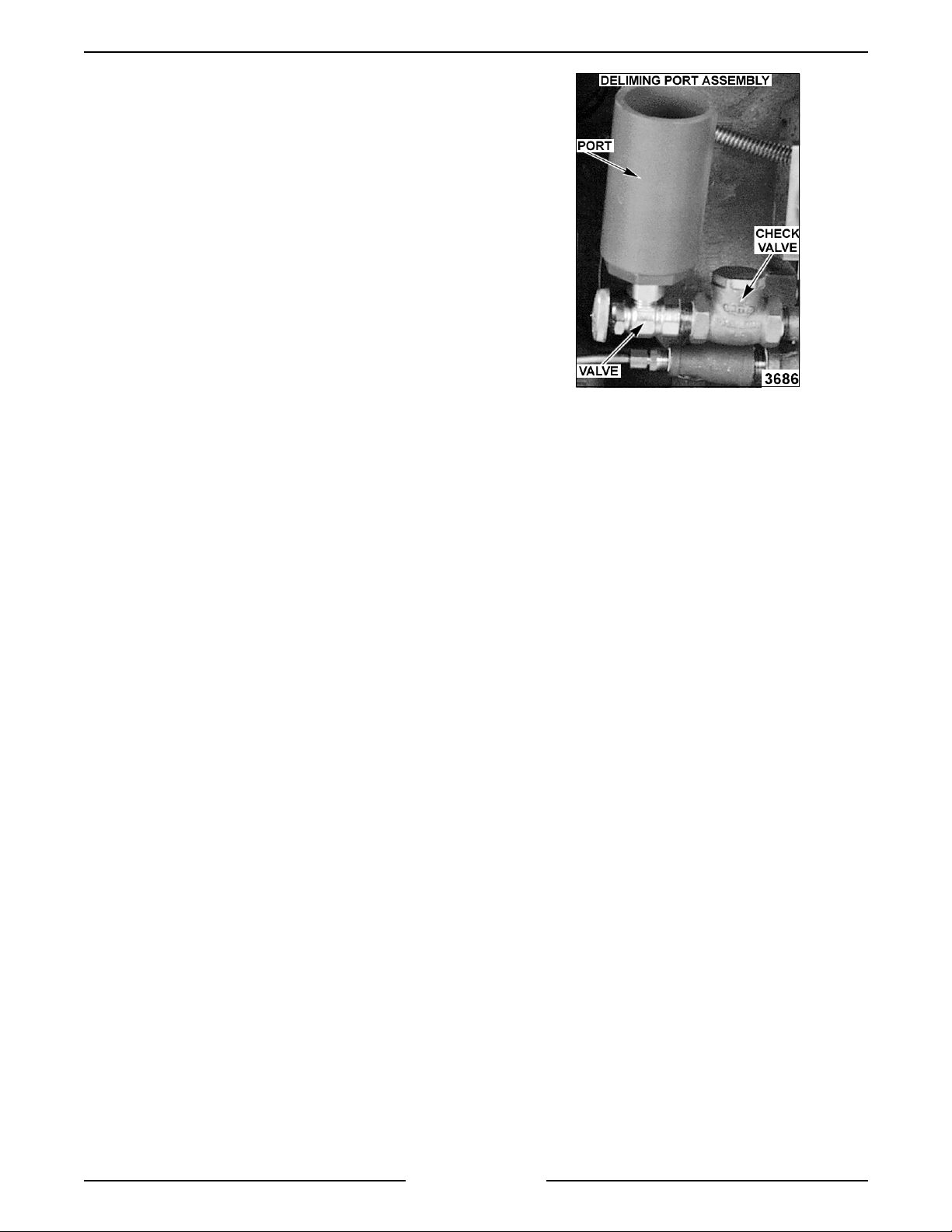
Check Valve
- On models with the deli me piping
assembly option, prevents the ejection of hot water
and steam out of the deli me funnel if the manual
delime fill valve were to be opened.
Delime Port Assembl y
- On models with the deli me
piping assembly option, allows the boiler and other
internal components to easily be delimed to remove
calcium, lime and rust bui ld up. See ”BOILER”
under “SERVICE P ROCEDURES”.
Standing Pilot (Gas Boilers)
- should always
remain lit t o light the main burners upon a cal l for
heat unless the steamer will not be in use for an
extended period. If the pilot flame goes out, wait 5
minut es before relighting.
Main Burn ers ( Gas Boilers)
- heats the water in
the boiler to generate steam.
Combination Control Valve (Gas Boilers)
- a gas
solenoid that opens t o allow gas flow when a call for
heat is made and also regulates the m anifol d gas
pressure.
Pressure Regul ating Valve (Direct &
Regenerated Steam)
- regulates the manifold
steam pressure between 10-12 psi.
Magnetic Contactor (E lectric Boil ers)
- when coil
is energized, suppl ies power to the electric heating
elements.
Heating Elements (Electric Boilers)
- heats the
water in the boi ler to generate steam.
Page 11 of 80
Page 12
VSX SERIES ST E A M E RS - COMPONENT FUNCTION AND LOCATION
Page 12 of 80
Page 13
VSX SERIES ST E A M E RS - COMPONENT FUNCTION AND LOCATION
Page 13 of 80
Page 14
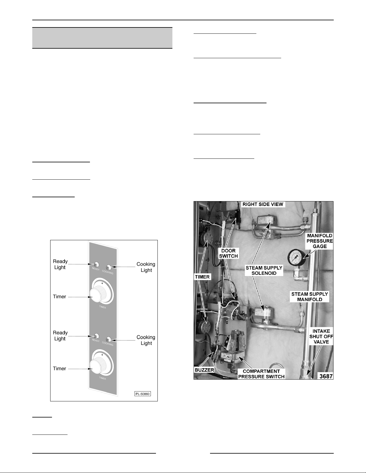
VSX SERIES ST E A M E RS - COMPONENT FUNCTION AND LOCATION
COOKING COMPARTMENT
CONTROLS
WARNING:
HOT. USE CARE WHEN OPERATING, CLEANING
OR SERVICING THE STEAMER. THE COOKING
COMPARTMENT CONTAINS LIVE STEAM. STAY
CLEAR WHEN OPENING EACH DOOR.
The upper section of the steam er c onsi sts of two
separate cooking compartm ents. Each compartment
functions independently with its own set of contr ols.
Power is supplied to t he c ontrols only after the
steam pressure rises above 3 psi to close the
compartment pressure switch. The switc h remains
closed as long as steam pressure stays above 3 psi
but will open i f the pressure drops below that setting.
Ready Light (Green)
is ready to cook.
Cooking Light (Red)
is in a cooking cycle.
Cooking Timer
tim e between 0-60 minutes. When a timer i s set, the
steam supply solenoid valve is energized to al low
steam int o the cooking compartment but only after
the boiler has reac hed its operating pressure. Also,
energizes the buzzer when time expires.
THE STEAMER AND ITS PARTS ARE
- when lit, indicates steam er
- when lit, indicates steam er
- use to set desired cooking cycle
Steam Solenoid Valve
allow steam into the cooking compartment (normally
closed v alve).
Compartment P r essure Switch
the control s only after the steam pressure rises
above 2. 3 psi to close the compartment pr essure
switch. The switch remains closed as long as steam
pressure stays above 2.3 psi but will open if the
pressure drops below that setting.
Manifold Pressure Gauge
of steam pressure in manifold. T he intake shut-off
valve should be adjusted so manifold pressure
remains at 9 psi with both compartments on.
Steam Supply Manifold
from the boiler for each cook ing compart ment.
Supplies steam up to the steam sol enoid valve.
Intake Shut-Off Valve
from the boiler to the steam suppl y manifold. This
valve should NOT be left fully OPEN to boiler steam
supply. See “INTAKE SHUT-OFF VALVE
ADJUSTMENT (STEAM FLOW) under “SERVICE
PROCEDURES”.
- when energized, opens to
- supplies power to
- indicates the amount
- main st eam supply line
- main st eam supply shut-off
Buzzer
turned off manually.
Door Switch
timer.
- signals end of a cook cycl e, must be
- removes electr ical power to the
Page 14 of 80
Page 15
VSX SERIES ST E AMER - SERVICE PROCEDURES
SERVICE PROCEDURES
WARNING:
MEASUREMENTS WHILE POWER IS APPLIED TO THE MACHINE. EXERCISE EXTREME CAUTION AT ALL
TIMES. IF TEST POI NT S ARE NOT EASI LY ACCESSIBLE, DISCONNECT POWER, ATTACH TEST
EQUIPMENT AND REAPPLY POWER TO TEST .
BOILER
Inspection
It is recommended that the boiler be thoroughly
inspected f or excessive scale and li me build up on a
quarterly basi s. In hard water areas or for units
heavily used, a more frequent interval should be
used. This inspection consists of an i nternal
examination and cleaning of the boiler shel l, an
examination and possibl e r eplacement of the
descaler, a check of li me build up on the water level
sensing probes, and a check of all boiler controls,
including the pressure switches.
Periodic servi c e must be perfor med as outlined in
these procedures. See “WATER CONDITIONING”
under “GENERAL”.
WARNING
INSTRUCTI ONS ON THE CLR BO TTLE. USE
PLASTIC OR RUBBER GLOVES TO AVOID SKIN
CONTACT. IF CLR LIQUID COMES IN CONTA CT
WIT H THE SKI N, RINSE WITH CLEAN W AT ER.
Clean-Out (All Boiler Models)
1. Turn steamer OFF and drain boiler.
2. Remove hand hol e plate and gasket (top front)
3. Remove ol d descaler retaining springs if
CERTAIN PROCEDURES IN THIS SECTION REQUIRES ELECTRICAL TEST OR
CABINET BASES
: READ AND FOLLOW THE
from the boiler by removing the nut and clamp,
then tapping t he c over lightly to free i t while
holding the c over stud. This prev ents the cover
from dropping into boiler.
present.
NOTE:
to nine gallons for both gas and el ec tric m odels
depending on the boiler size and BTU/KW rating.
NOTE:
contact wit h steamer components, lightly rinse of f
with clean water.
Boiler water c apac ities vary between seven
If deliming solution acc idently comes in
A. Models with Blowdown Timer
deliming solution into boiler shell. Mix the
solution in accordance with the instructions
on its container. Proceed to step 9.
B. Models without Blowdown Timer
the incoming water supply. Turn the unit
ON to close t he dr ain valve. Pour deliming
solution into boiler shell. Mix the solution
in accordance with the instruct ions on its
container. Proceed to step 9.
C. Models with Del iming P ort Assembly
Before mixing and pouring del iming
solution into boiler , clean the seati ng
surfaces for the hand hole gasket and then
install a new gasket. Position t he hand
hole plate and tighten down. Turn off the
incoming water supply. Tur n the unit ON
to close the drain valve. Open the
deliming assembly valve and pour the
deliming solution into the port. Mix the
solution in accordance with the instructions
on its contai ner. Close the deliming
assembly valve and proceed to step 10.
- Pour
- Turn off
-
4. With a wire brush, or equivalent, dislodge and
remove all loose scale from boiler shel l. The
loose mater ial must be either scooped fr om the
boiler or flushed through t he dr ain.
5. Check probe canister and f loat valve assembly
(regenerated models) for a scale build up and
clean as necessary.
6. Check drain hole f or obstructions.
7. Install two new descalers.
8. Mix the deliming solution according to the
instructions for the chemical in use then add
solution to boiler.
Page 15 of 80
9. Clean the seating surfac es for the hand hole
gasket and then Instal l a new gasket. Position
and tighten t he hand hole plate.
Page 16
VSX SERIES ST E AMER - SERVICE PROCEDURES
10. Cooking c ompartm ent timers are to be in the
OFF position. Turn the boiler switch ON and
open water valve if necessary.
11. Boiler is to operate under pressure for 90
minut es or per the instructions for the chemical
in use.
12. Drain boiler by normal methods. Refill boiler
and allow heat until f ully pressurized.
13. Repeat step 12 thr ee times.
14. The steamer is now ready for nor mal operation.
Deliming Only
(Models with Deli ming Port Assembly)
Boiler delim ing should be perfor med on a weekly,
bi-weekly or monthly basi s, depending on the quali ty
of the local water supply.
On steamers using a water purifi c ation system,
follow the instructions for that system to deli me the
boiler. Only use the type of chemical recommended
or described in the instructions for deliming wit h this
type of system.
1. Turn steamer OFF and drain boiler.
2. Mix the deliming solution according to the
instructions for the chemical in use then add
solution to boiler.
NOTE:
Boiler water c apac ities vary between seven
to nine gallons for both gas and el ec tric m odels
depending on the boiler size and BTU/KW rating.
NOTE:
If deliming solution acc idently comes in
contact wit h steamer components, lightly rinse of f
with clean water.
A.
Models with Blowdown Timer
- Open
the deliming assembl y valve and pour the
deliming solution into the port. Mix the
solution in accordance with the instructions
on its contai ner. Close the deliming
assembly valve and proceed to step 3.
B.
Models without Blowdown Timer
- Turn
off the incoming water supply. Turn the
unit ON t o close the drain valve. Open the
deliming assembly valve and pour the
deliming solution into the port. Mix the
solution in accordance with the instructions
on its contai ner. Close the deliming
assembly valve and proceed to step 3.
3. Top compartments are to be in the OFF
position. Turn the boiler switch ON and open
water valve if necessary.
4. Boiler is to operate under pressure for 90
minut es or per the instructions for the chemical
in use.
5. Drain boiler by nor mal m ethods. Refill boiler
and allow to heat up and build steam pr essure.
6. Repeat step 5 three times.
7. Unit is now ready for normal operation.
Descaler
The descaler i s accessible through the hand hole
opening. It is a coiled wire wound around a solid
cylindrical cor e, and hangs by an open loop from the
shell's horiz ontal stay rod, about 4 inches from the
front of the shell . If t he wi r e is eaten through, or if
the core of the descaler is eaten away to half its
original size, a new descaler should be i nstalled.
To install a new descaler, stretch its wire coil so that
the descaler hangs with i ts core completely below
the mi nimum water level in the boiler, but hanging
free. The descaler must not contact the bottom of
the boiler shell, elec tric heating element s or t he
regenerating steam coil s on uni ts so equipped.
Water Level Cont rols
(Low L evel Cut-Off and Different ial)
Solid State
1. Ensure that water is filling the boiler.
2. Check for correct voltage being applied to the
board.
3. Verify the water level control boar d oper ation
as outlined in “WATER LEVEL CONTROLS”
under “ELECTRICAL OPERATION”.
A. Does the HL LED light up and the HL r elay
energize to change the contact stat e at
power on?
B. As the boiler fills, does the LLCO LED light
up and the LLCO relay energize to change
the contact state after the water level
reaches the LLCO probe?
Page 16 of 80
Page 17

VSX SERIES ST E AMER - SERVICE PROCEDURES
C. Does the HL LED go out and the HL relay
de-energize, allowing the cont ac t state to
switch back to i ts starting condition after
the water level reaches the HL pr obe?
4. If water is in t he boiler but is not being detected
by the water level probes, the probes may need
cleaned and/or boiler delimed. See “BOILER”.
5. After checking the abov e items, if the water
level control board does not appear to be
functioning as outlined, then repl ac e the board.
6. Check unit for proper operation.
Electro Mech anical
WARNING:
DISCONNECT THE ELECTRICAL
POWER TO T HE MACHINE AT THE MAIN
CIRCUIT BO X. P LA CE A TAG ON THE CI RCUIT
BOX INDICATING THE CIRCUIT IS BEING
SERVICED.
Loose electri c al connections may prev ent the heat
from coming on or may cause the boiler to overfill.
Accumulation of boiler scale on or near the sensing
probes may cause them to retain water on the
insulator surface. This may prevent the boiler from
filling or cause dry firing. Dry firing will result in
damage to heating elements or to the boiler. Verify
the water level cont r ols operation as outlined in
“WATER LEVEL CONTROLS” under “ELECTRICAL
OPERATION”.
With the individual probe l ead wir e r emov ed, check
the probes and contactor s as outl ined below:
1. With an ohmmeter , check the probe bet ween
the wire connection and shell. An open c ircuit
should be present when the boiler is empty. If
resistance is present, r emov e and c lean the
probes. Also check for a cracked insulator, then
reinstall probes and check. When the boiler is
full of water, a resistance reading should be
measurable bet ween the probes and shell only.
NOTE:
Actual resistance reading will depend on
water qualit y and pr obe c ondition.
2. Check low level and dif ferenti al water level
controls. Wi th the power switch ON, use a
voltmeter to check the i nput voltage across
terminals 1 & 2. Meter shoul d r ead 115V . With
the boiler empty, ac r oss terminals 9 & 10, y ou
should read 300 to 350V. If you do not r ead this
voltage, then coil is bad and contac tor should
be replaced.
3. Remove sensing probe. First rem ove the
bolted cover over the sensor cluster. Then
remove the wire from the pr obe and unscrew
the probe with a wrench. Be c ar eful to note the
locati on of each probe and the number of the
wire connected to it. Incor r ec tly connected
wires will cause the controls to malfunction.
4. Clean probe thoroughly, r emov ing ALL deposits
from the insulat or . Do not use an abrasiv e on
the insulator; use a soft cl oth.
5. Inspect through the probe socket for the
presence of water. Water must drain from the
probe housing. If in doubt, pour water into the
housing and observe that it drains quickly. If
the housing fails to drai n, remove the housing
or housing cover and clean the interior
mechanically.
Water Level Gauge Assembly
Close the valve at the top and at the bottom of the
gauge assembly. Unscrew the packing nuts at the
top and bottom of the glass tube. Slide the glass
tube upwards, until the bottom of the tube is clear of
the fitting and lift it out.
When r einstalling the tube, use new sealing
washers. Do not over t ighten the packing nuts; it
could break the gauge glass. Check that both top
and bottom valves are f ully open.
Pressure Swit ches (Gas and E lectric Models)
WARNING:
DISCONNECT THE ELECTRICAL
POWER TO T HE MACHINE AT THE MAIN
CIRCUIT BO X. P LA CE A TAG ON THE CI RCUIT
BOX INDICATING THE CIRCUIT IS BEING
SERVICED.
Remove the boil er control box cov er to access the
two controls. T he pr essure switch on the left is the
cycling or prim ar y c ontrol; the one on the right i s the
high li mit c ontrol. They ar e identical switches,
differing only in their settings.
Turn the power ON and l et the boiler c ome up to
pressure. Aft er the ready light comes ON, t ur n one
of the cook ing compartment timers on to exhaust
steam f rom the boi ler. Observe boiler pr essure
gauge readings for sev eral cycles and compare
them with the pressure settings in the chart. If the
readings differ, adjust the pressure settings as
described below.
Two slotted and square headed adjustment screws
extend thr ough the top of t he swit c h c ase with dials
and pointers to indicate the appr oxim ate setting.
The adjustment screw directl y above the dial
changes both the cut-out (off) and the cut-in (on)
points. Set it first to give the proper off setting.
Turning the scr ew cl oc k wise i ncreases the pressure.
Then set the second adjustment screw to give the
proper on setting. The pressure settings for eac h
switch are li sted below.
PRESSURE SETTINGS (PSI)
CYCLING HIGH LI MIT
UNIT ON OFF ON OFF
Gas 8 10 6 15
Electric 11 13 6 15
Page 17 of 80
Page 18

VSX SERIES ST E AMER - SERVICE PROCEDURES
High Limit Thermostat
WARNING:
DISCONNECT THE ELECTRICAL
POWER TO T HE MACHINE AT THE MAIN
CIRCUIT BO X. P LA CE A TAG ON THE CI RCUIT
BOX INDICATING THE CIRCUIT IS BEING
SERVICED.
Remove thermostat (bi-metallic disk type) and
inspect f lat surfac e of thermostat for c or r osi on or
rust. Replace if rusted.
Clean thermostat mount ing and thermostat surfaces
before remounting or r eplacing. A good
metal -to-met al contact is essential for pr oper
functioning of the thermostat. This service m ust be
performed at least once a y ear .
On gas boilers, the high li mit t her mostat is loc ated
on the face of the boiler close to t he si ght glass on
the right side. For access, remove t he small metal
cover placed ov er the therm ostat.
On electr ic boil er s, the high li mit t her mostat is
located behi nd the contactor box cover. On elec tric
boilers with two heating elem ents, the therm ostat is
connected to one of the heating element lugs. On
electric boiler s with four heati ng elements, t he
thermostat is located bet ween the center pair of
element s at the top of t he elements.
Removing The Boi ler Assembly
WARNING:
DISCONNECT THE ELECTRICAL
POWER TO T HE MACHINE AT THE MAIN
CIRCUIT BO X. P LA CE A TAG ON THE CI RCUIT
BOX INDICATING THE CIRCUIT IS BEING
SERVICED.
WARNING:
SHUT OFF THE GAS BEFORE
SERVICING THE UNIT.
WARNING:
ALL GAS JOINTS DISTURBED
DURING SERVI CING MUST BE CHECK E D FOR
LEAKS. CHECK WITH A SOAP AND WATER
SOLUTION (BUBBLES). DO NOT USE AN OPEN
FLAME.
A. CHECK ALL JOINTS PRIOR TO THE
GAS VALVE (SOLENOID) BEFORE
LIGHTING UNIT.
B. CHECK ALL JOINTS BEYOND GAS
VALVE (SOLENOID) AFTER UNIT IS LIT.
Blow down the boiler and
Newer Steamer Mod els
-
allow to cool, if necessary. Ensure that all utilities to
the steamer are off. Drain any ex cess water from
the boiler . Disconnect the steam supply line, power
leads and drain l ines from the cooking compartment
top to the boi ler base. Remove the cooking
compartment top by unscrewing the bolts holdi ng
the cooking compartment top to the boiler base. The
bolts are loc ated behind the small louvered access
panels on the left and right side of the steamer. Lift
the top of f the boiler base and place to t he si de.
Remove the remaining plumbing and elec trical
connections from the boiler to t he c ontrols. Remove
the bolts securi ng the boiler t o the frame and lift it
out. Reverse procedure to i nstall a new boiler.
Older Steamer M odels
- Blow down the boiler and
allow to cool, if necessary. Turn off all utilities to the
steamer and di sconnect supply lines. Dr ain any
excess water from the boiler. Remove the screws
holding any control box that would obstruct removal
of the boiler through the front of the base.
Disconnect the 1/4 inch diameter water inlet tubing.
Disconnect the wir e and c onduit fr om the low water
cut-of f probes, high limit thermostat, and the
automatic blowdown valve (if so equipped).
Uncouple the uni on on the steam outlet and blow
down the lines.
Remove all t he scr ews holdi ng the flue and flue
collector to the base. Remove t he anc hor screws
holding the boiler to the frame. Sli de the boiler
forward. T he bur ner box, anchored onl y by the
boiler, must be prevented fr om slidi ng forward with
the boiler .
Fill and Cold Water Solenoid Valves
WARNING:
DISCONNECT THE ELECTRICAL
POWER TO T HE MACHINE AT THE MAIN
CIRCUIT BO X. P LA CE A TAG ON THE CI RCUIT
BOX INDICATING THE CIRCUIT IS BEING
SERVICED.
Removal
1. Turn off the water supply to the steamer.
2. Open the base doors and remov e the two
screws from the top of the boiler control box.
3. Pull the quick connect power leads off the
solenoid valve being serviced.
4. Disconnect the water li nes for the valve being
servi ced and remove the valve from the unit.
5. Reverse procedure to install.
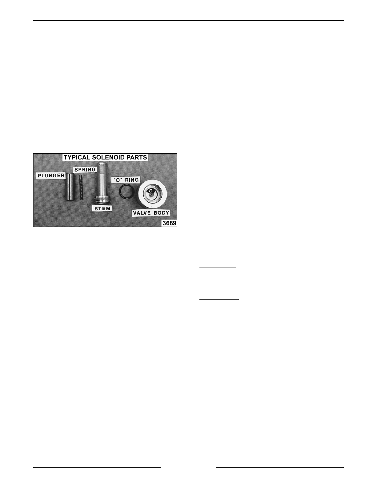
Disassembly
NOTE:
It is recommended that the v alve be
removed from the unit for cl eaning to prevent
damage to the lines and fittings when the stem is
removed from the body.
1. Remove the c oil assembly from the valve stem
by lifting up on t he retaining c ap at the top of
the solenoid valve and sliding the met al cov er
plate off.
2. Clamp the body of the v alve in a vise.
3. Mark a scribe line on the stem nut to the valve
body for proper retightening.
Page 18 of 80
Page 19
VSX SERIES ST E AMER - SERVICE PROCEDURES
4. Remove the stem locking nut to remove t he
stem f rom the valve body.
5. All parts are now accessible for inspecti on and
cleaning.
NOTE:
If internal solenoid parts appear to be
damaged or worn, then r eplace the solenoid valve.
Do not reuse damaged or worn parts. No internal
solenoid parts are available as a service
replacement. Pay careful attention to proper
orientation and placement of parts during
reassembly.
A. Check rubber seal on bottom of plunger .
B. Check plunger spring.
C. Check O-ring in valve body.
D. Check ports in valve body.
6. Reverse procedure to install.
Water Not Being Supplied to Boiler
Turn the steamer on. Check that water suppl y is
available to the steamer. A fter approximately 10
minut es, if no water is observed in t he water level
gauge sight glass, then chec k for a problem with the
water solenoid valve or water level cont r ol probe.
WARNING:
DISCONNECT THE ELECTRICAL
POWER TO T HE MACHINE AT THE MAIN
CIRCUIT BO X. P LA CE A TAG ON THE CI RCUIT
BOX INDICATING THE CIRCUIT IS BEING
SERVICED.
Scalants may be cov er ing the water level cont r ol
probe giving a f alse indicat ion of a suf ficient water
level in the boiler. Detach, remove and thoroughly
clean the water level probe and canister assembl y
to remove scalant s and l ime build up. This condition
indicat es extremely poor water quali ty being
supplied to the boiler and/or boiler cl ean out/and
deliming has not been performed. T he water
conditi on must be cleared up imm ediately wit h a
proper water condit ioner to avoid f ur ther problem s
with the steam er . Replace the water l evel pr obes
and canister assembl y . Perform a boiler c lean-out
and deliming procedure. S ee “BOILER”.
Water may be draining through an open boiler
blowdown solenoid v alve as qui c k ly as it’s fed to the
boiler. Loose wiring, a burned out coil or particles of
scale trapped i n the valve seat may prevent the
valve from closing.
Newer steamer models use a plunger type rod that
raises and lowers to permit steam/water flow out of
boiler. If debris has accumulated around the water
orif ice, the plunger may not seat pr oper ly to close
off the opening. I f this symptom i s suspect, remov e
the solenoid as outlined in “FILL AND COLD
WATER SOLENOID VALVES”. Remove any debris
found on seali ng surfaces, reassemble and install. If
the solenoid valve still does not function properl y ,
replace it with a new valve and chec k for proper
operation.
Older steamer model s have a movable blade and
when closed, the blade reac ts as a guillotine that
should be free t o move fully down into the valve
pocket (projection at bottom of valve) so that the
pierced hole in the blade aligns perfectly with the
body opening. If debris has accumulated in the
bottom of the valve pocket, then the blade will not
move into the pocket completely. If this symptom is
suspect, remove the solenoid as outlined i n “FILL
AND COLD WATER SOLENOID VALVES”.
NOTE:
On this valve body, remove t he two
assembly bolts holding the brass body together and
remove the loose i nternal parts. Remove any debr is
found on seali ng surfaces, reassemble and install. If
the solenoid valve still does not func tion properly ,
replace it with a new valve and chec k for proper
operation.
Blowdown Solenoid Valve Does Not Drain
If your steamer has an automatic blowdown drain
valve.
Older Models
- when the blowdown timer button is
pressed, the boiler blowdown valve opens. If y our
steamer has a manual blowdown drain v alve, close
the v alve.
Newer Models
- are equipped with nor mally open
solenoid valves that close when energized by the
main power switch. When the main power switch is
turned off, the solenoid valve is de-energized and
the boiler blowdown valve re-opens.
The water contai ned in the boil er , being under
pressure, should be blown through this valve and be
noticeabl y visible exhausting out the steam er dr ain.
If t he blowdown operation appears to func tion
sluggishly or not at all, considerable scalants may
be lodged in the dr ain pipe and/or the valve.
Disconnect the valve f rom the drain line and i nspect
both the valve and the drain pipe fixed to the boi ler.
If consi derable scalants or l ime build up is apparent,
then not only the valve, but also the boiler and water
level control must be thoroughly cleaned. S ee “FILL
AND COLD WATER SOLENOID VALVES” for a
cleaning procedure of a solenoid valve and
"BOILER” for a cleaning proc edur e of the boiler.
Page 19 of 80
Page 20
VSX SERIES ST E AMER - SERVICE PROCEDURES
Steamer Achieves Pressure Sl ower Th an Normal
If t he boiler requires more than 15 minutes (20
minut es for regenerated models) to achi eve normal
operating pressure as li sted in below, then check the
following conditions.
NORMAL OPERATING
STEAM PRESSURES
UNIT RANGE (PSI)
Gas 8 - 10
Electric 11 - 13
Direct 10 - 12
Regenerated 10 - 12
1.
All Models (With Boiler)
A. A heavy bui ld-up of scal ants has possibly
coated the interior of the boil er . The
insulating eff ect of the scalants hampers
heat transfer. Unbolt and remov e the hand
hole cover plate and gasket assembly.
Exam ine interior of boiler and if scalants
and/or li me buil d up is apparent, perform a
boiler clean-out and deliming pr oc edur e.
See “BOILER”. If consi der able scalants
are evident, then bot h the boiler blowdown
solenoid valve and the water level control
must also be examined.
2.
Gas Model s
A. Low incoming gas pressure causes
reduced BTU output . Check incoming line
and manifold gas pressures as outlined i n
“MANIFOLD PRESSURE ADJUSTMENT.”
B. Gas combination control valve
malfunction. Check incoming and manifol d
gas pressures as outlined in “MANIFOLD
PRESSURE ADJUSTMENT.” If pressure
adjustment s are made and mani fold
pressure remains low, replace the
combination valve and test unit for proper
operation.
C. Gas burner ports clogged or obstruction
around air shutter . After a per iod of time,
gas burners can accumul ate carbon in
their ports or become clogged by food and
grease debris from kitc hen c leaning,
restrict ing performance. To clean burners,
remove them from burner box and boil in
water for 10 -15 minutes to dislodge clog.
Clean-out any remaining debris from the
gas ports using a wire brush, scribe or pic
type met al instrument. Remove any other
forei gn objects that appear to be
obstructing the gas ports or air shutters.
D. Gas orifice clogged or obstructed around
air shutter. It is possible for debris to
become lodged in the smal l gas orifice
opening over time. Clean-out the gas
orif ice using a round m etal instrument of
the same hole diameter or sl ightly sm aller.
Clean as needed. If clogging r eappear s,
the orifice should be remov ed, cleaned
and reinstalled. Remove any other foreign
objects that appear to be obstructi ng the
gas orifice or air shutt er s.
3.
Electric Mo dels
A. Heavy scale build up on heating element
causes reduced heating.
B. One or more elec tric heating element s
malfunctioning.
C. One or m or e magnetic c ontactors not
pulli ng in, to power heati ng elements.
D. If unit operates under three phase power,
then one of t he phases m ight be lost.
4.
Direct Steam Models
A. Building steam supply pressure low.
B. Cooking compart ment steam sol enoid
valve malf unc tion.
C. Steam pr essure regulator adjusted too
low.
D. Clogging in the steam line reduces steam
supply.
5.
Regenerated (S t eam Coil) Steamers
A. Heavy scale build up inside copper steam
coil.
B. Building steam supply pressure low
C. Cooking compartment steam solenoid
valve malf unc tion.
Page 20 of 80
Page 21
VSX SERIES ST E AMER - SERVICE PROCEDURES
Inlet Water Strainer
The in-line Y strainer shoul d be located upstream of
the fill valve solenoid. Unscrew the cap f r om the
body on the leg of the Y that shoul d be pointing
downwards toward the floor. Remove the screen
and any foreign particles trapped in the opening.
Rinse the screen thoroughly to remove accumulated
debris and replace the screen in the valve body. If
screen can not be thoroughly cleaned, replace it
with a new one. Reinstall the cap and ensure that
the Y strainer is positioned with t he c ap pointing
downward to catch debris.
The pressure regulating valve strainer will become
clogged if dirty steam lines are connected to dir ec t
steam models. Remove the hex nut on the bottom
of the pressure regulating valve to clean the strainer
and valve seat.
GAS MODELS
Pilot, Thermocouple or Main Burners
WARNING:
POWER TO T HE MACHINE AT THE MAIN
CIRCUIT BO X. P LA CE A TAG ON THE CI RCUIT
BOX INDICATING THE CIRCUIT IS BEING
SERVICED.
DISCONNECT THE ELECTRICAL
NOTE:
settings are m ade, always replace the adj ustment
cover scr ew to assure proper gas control operation.
If adjustments in gas or pilot pressure
WARNING:
SERVICING THE UNIT.
The pilot thermoc ouple supplies a millivolt signal
(DC) to an int ernal solenoid valve on the gas
combination control valve when heated. This
solenoid valve is designed to shut off the gas flow to
the pilot and main bur ner s i n c ase of a malfuncti on
in the system . When ener gized by the thermocouple
voltage, the valve is held in the open positi on to
permit gas flow. The pilot burner flame is controlled
by an adjustable needle valve located under a small
cap screw on the combi nation control valve.
When experiencing nuisance pil ot outages, v isually
check pilot flame for the proper contact on
thermocouple and the flame color. Also, chec k to
see that unusually str ong floor drafts are not
interfering with pr oper heating of the thermocouple
by the pil ot flame.
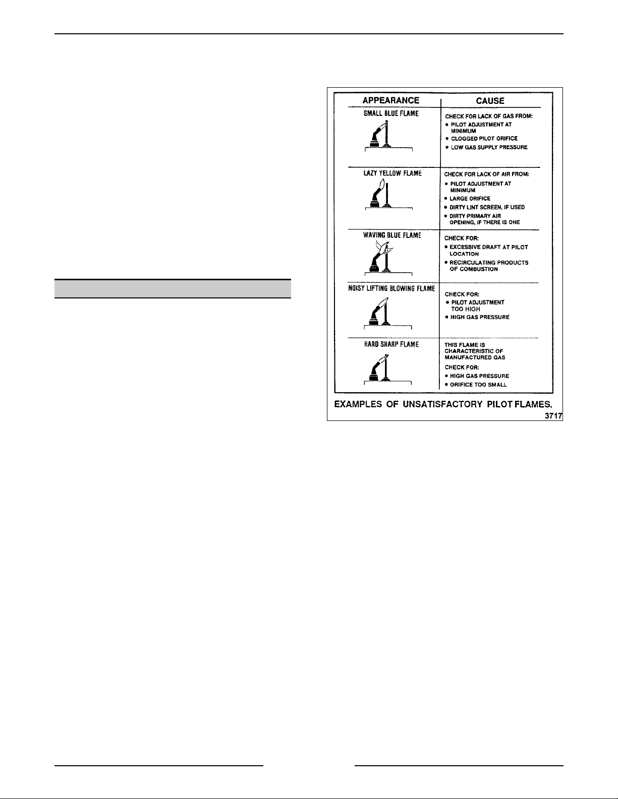
The pilot flame should be a steady blue flame that
envelopes the thermoc ouple tip. The flame should
be about one inch l ong wi th half its length extending
beyond the outer edges of the pilot shield. If the pilot
flame does not appear to be this length and color ,
then an adjustment is necessary. See the diagram
below for an example of un satisf ac tory pilot flames.
Turn cloc k wise to dec r ease pi lot flame and
counterclockwise to increase.
SHUT OFF THE GAS BEFORE
If adjustment does not resul t in a pil ot flame of
proper size, t hen gas might not be flowing properly
to the pilot. Check for a plugged pi lot orifice, a
kinked or plugged pilot gas supply tube and for l ow
gas supply pressure. The pil ot operates unregulated
at gas supply pressures while the pressure regulat or
in the combination control valve regulat es pressure
to the main burners only. V isually check the
thermocouple tip (hot end) and tube lead for kinks or
pinches that might be causing a short between the
tube and the wire i nsi de. Also, check t he threaded
connector tip for cor r osi on, tarnish or dir t which can
cause a poor connection. If t he thermocoupl e shows
either of these signs, it shoul d be r eplaced with a
new one.
NOTE:
thermocouple tip t o the control valve is an elec trical
connection and must be clean. Do not use any
sealing compound on the threads or over tight en the
threaded connection. Finger tighten the nut plus 1/4
turn with a wrench. O ver tightening the nut could
crush the insulat or , shorting the ther mocouple.
If t he pilot flame is correct and ther e ar e no dr afts,
then the problem is in t he thermocoupl e output
voltage or the gas solenoid valve in the combination
control.
The connecti on of the tubing from the
Page 21 of 80
Page 22
VSX SERIES ST E AMER - SERVICE PROCEDURES
Check the thermocouple output voltage (DC
millivolts) with a VOM. If a meter is not available,
replace the t hermocouple with a new one and
recheck operation. Fir st, take a closed ci r c uit
reading (adaptor r equired) with the pilot on. Next,
take an open circuit readi ng by disconnecting the
thermocouple tube from the valve and connecting
meter leads to the tube and threaded end. Manually
press and hold down OFF/PI LOT/ON knob and light
the pilot. All ow the pilot to heat the therm oc ouple for
one to two minutes and compare the readings with
the chart bel ow.
THERMOCOUPLE
MV
READINGS
CLOSED
CIRCUIT
Typical 15
Range 10 - 20 20 - 35
OPEN
CIRCUIT
If either of the readings is less than the minimum or
thermocouple is not operating as described, replac e
the therm ocouple. To replace, rem ove the pilot
assembly by di sconnecting thermocouple and pilot
gas supply tubing from the c ombination control
valve and remov e the two screws holding the pil ot
to its brack et. Replace the thermocoupl e or pilot
assembly and check for proper operat ion. If after
replacing thermocouple, the pilot or main burners
are still not functioning properly, then a problem in
the gas combination control valve exists as well.
Replace the combination control valve as outlined in
“GAS COMBINATION CONTROL VALVE
REPLACEMENT” then check for pr oper oper ation.
NOTE:
Gas combination control valves are not
servi ceable and should not be di sassembl ed. Once
you have isolated the problem to t his control,
replace it. Do not attempt to repair the assembly.
The mai n burners are lanced port steel burners (5 or
7 burners, depending on the unit) and have
adjustable air shutters. Fi xed orifice type hoods are
used to establish the gas flow to each burner. Set
each burner air shutter opening just large enough to
eliminate any yellow tip i n the burner flame.
To remove main burners, lift burner and sl ide it to
the rear just enough to clear the gas ori fice hood.
Lower the front end of burner and bri ng it for ward
under the manifold pipe. When reinstal ling burners,
ensure that locating pin i s i n the hole for pr oper
positioning and to prevent burner f r om roll ing over .
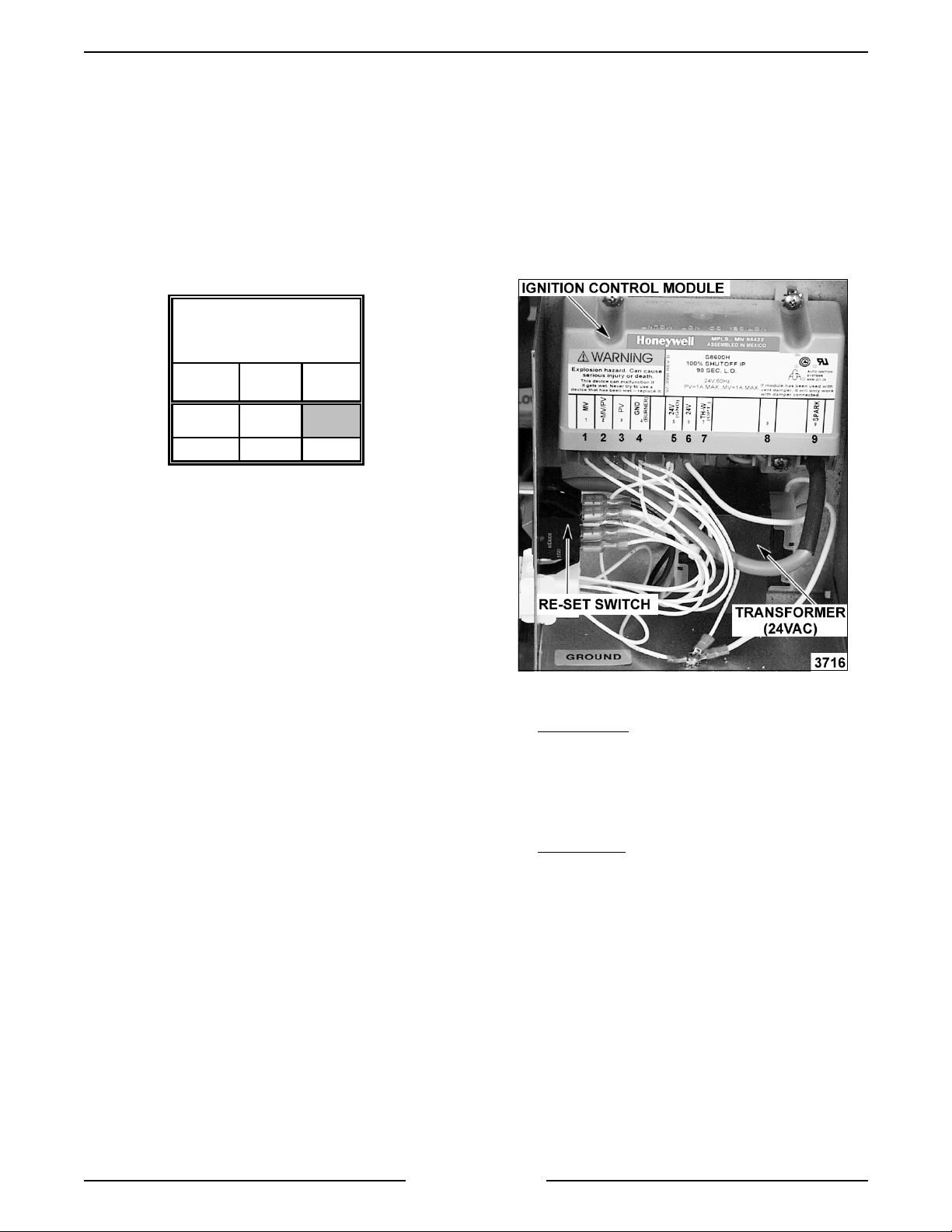
Automatic Ignitio n Systems
When the main power switch is turned ON and the
ignition control modules reset switch is i n the ON
position, the ignit ion control module is energized
with 24 v olts between terminals five and six.
High voltage is sent from t er minal nine to the spark
electrode and an out put of 24 volts i s sent from
terminals two and three to the pilot coil in the
combination valve, allowi ng gas to flow to the pilot.
The sparking will continue for 90 seconds or until
the flame sensor has confi r med that an adequate
pilot flame is present.
Once the pilot flame is confirmed, a 24 volt output
from terminal one will be sent, allowing the cycling
coil of the com bination valve to operat e at the
request of the cycl ing pressure switch.
Terminals:
1. Main Voltage
- 24V AC will be present on
terminal #1 with the pilot sensing elec trode
sensing an adequate pilot fam e. This output will
remain present as long as the pilot flame
remains adequat e.
2. Common (MV/P V ).
3. Pilot Voltage
- 24V AC will be present on
terminal #3 at the instant an input voltage is
supplied to the module. This voltage will
remain present on terminal #3 providing an
adequate pilot flame is established within 90
seconds. In the event that an adequate pilot
flame is not establ ished within 90 seconds this
output voltage will drop out.
4. Ground (burner).
5. Ground (24VAC Neutral) .
6. 24V AC Input.
7. High Voltage to spark el ectrode (The pi lot
flame current is sensed by the Ignitor Module
via the spark elect r ode high voltage wire and
terminal #9).
Page 22 of 80
Page 23
VSX SERIES ST E AMER - SERVICE PROCEDURES
Spark Ignition Control Test
1. If the ignition contr ol modul e does not appear
to be sparking to ignite gas, perform t he
following checks.
A. Check to ensure that all electrical terminal
connections on the igniti on c ontrol module
and the ignitor are clean and t ight.
B. Verify that the ignition contr ol module and
the ignitor have good ground wire
connections. The ignitor mounting brac k et
should have good metal t o metal c ontact
to its m ounting surfac e.
C. Turn the main power switch ON. Turn the
ignition control modules re-set switch OFF
then ON.
D. Check f or 24V A C output on the ignition
control module transformer.
1) If 24VAC is present then replace
ignition control module and re-t est.
2) If 24VAC is not present t hen ensure
that transformer is receiving 120VAC
input. I f igni tion control module
transformer is recei ving pr oper
voltage, then replace ignition control
module t ransformer and r e- test.
2. If the ignition contr ol modul e and transform er
are funct ioning properly, then check the
following ignitor conditions.
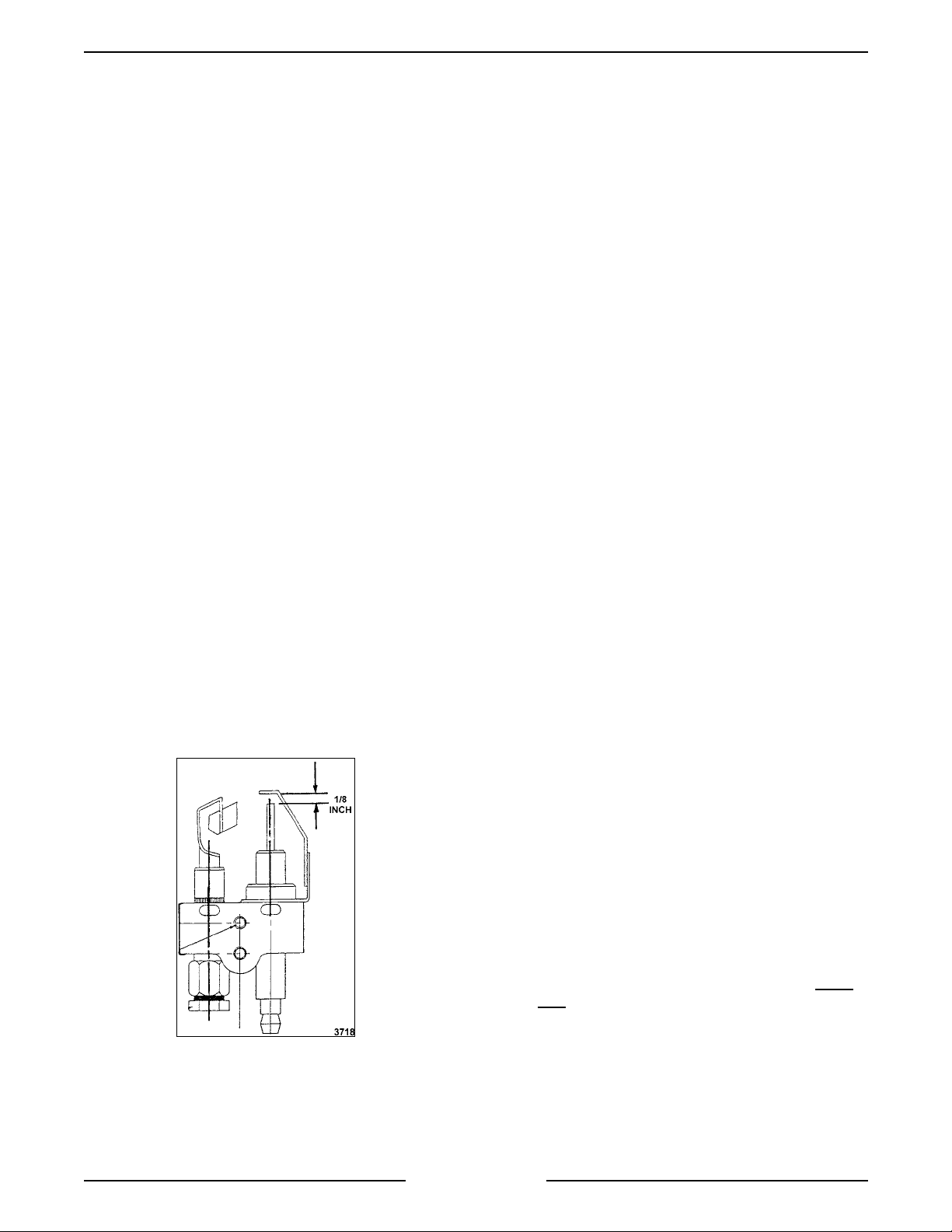
A. The gap between the spark probe and the
ground clip should be approximately 1/8
inch. If the gap appears to be excessive or
poor sparking is occur r ing, remove the
electronic ignition pil ot and adjust gap.
C. Check the i gnition cable for tightness or
damaged insulation.
3. Check unit for proper operation.
Gas Combination Co ntrol Valve Replacement
WARNING:
DISCONNECT THE ELECTRICAL
POWER TO T HE MACHINE AT THE MAIN
CIRCUIT BO X. P LA CE A TAG ON THE CI RCUIT
BOX INDICATING THE CIRCUIT IS BEING
SERVICED.
WARNING:
SHUT OFF THE GAS SUPPLY
BEFORE SERVICING THE UNIT.
WARNING:
ALL GAS JOINTS DISTURBED
DURING SERVI CING MUST BE CHECK E D FOR
LEAKS. CHECK WITH A SOAP AND WATER
SOLUTION (BUBBLES). DO NOT USE AN OPEN
FLAME.
A. CHECK ALL JOINTS PRIOR TO THE
GAS VALVE (SOLENOID) BEFORE
LIGHTING UNIT.
B. CHECK ALL JOINTS BEYOND GAS
VALVE (SOLENOID) AFTER UNIT IS LIT.
NOTE:
Gas combination control valves are not
servi ceable and should not be di sassembl ed. Once
the problem has been isolated to t his control,
replace it. Do not attempt to repair the assembly.
Remove the two screws on the control box cov er .
Disconnect electrical supply wires and conduit
running to the c ombination control valve.
Disconnect the thermocoupl e lead and pilot gas
supply tube f rom control and pipe connections on
each side of t he control. Reverse procedure t o
install and check unit for proper operat ion.
Manifold Pressure Adju st ment
B. Inspect the ceramic flame rod insul ator for
cracks or evidence of exposure to ex treme
heat, which can permit leakage to ground.
If either of these conditions exist, then
replace the pilot i gnitor assembly.
Page 23 of 80
WARNING:
DISCONNECT THE ELECTRICAL
POWER TO T HE MACHINE AT THE MAIN
CIRCUIT BO X. P LA CE A TAG ON THE CI RCUIT
BOX INDICATING THE CIRCUIT IS BEING
SERVICED.
WARNING:
SHUT OFF THE GAS SUPPLY
BEFORE SERVICING THE UNIT.
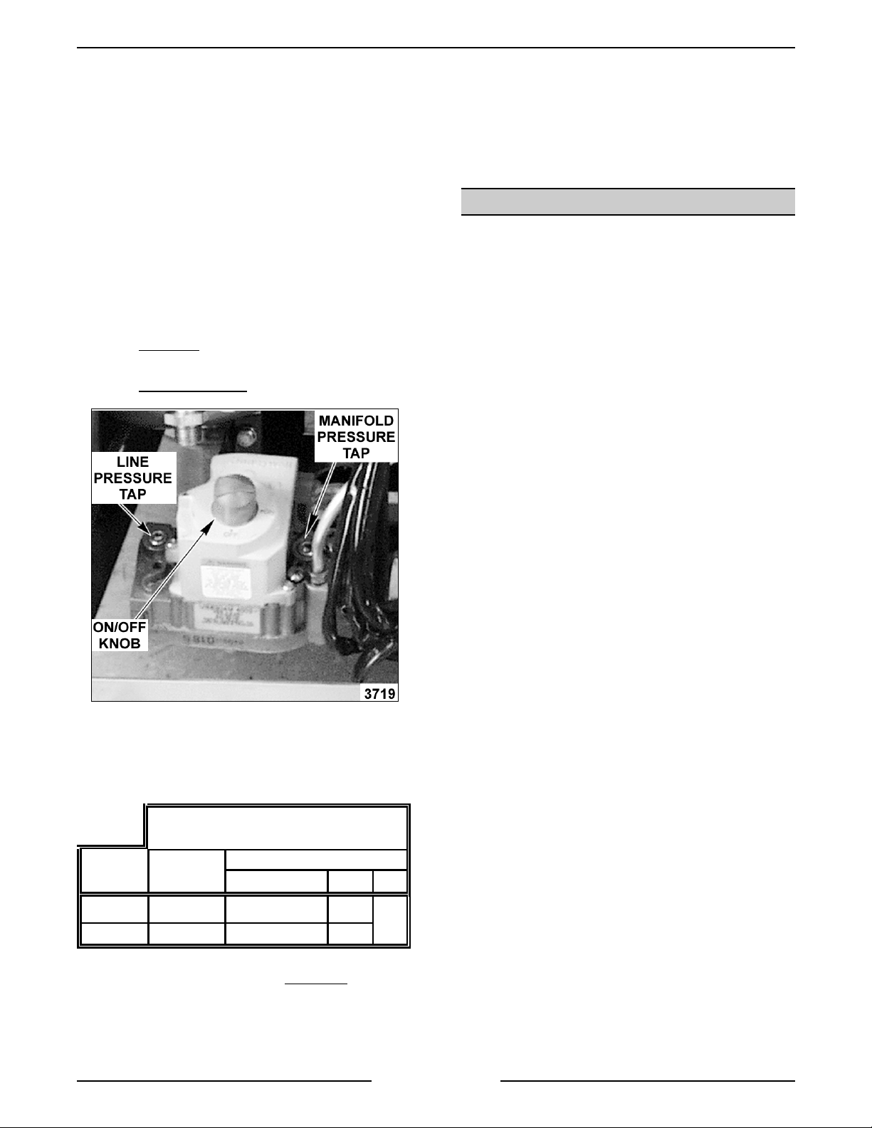
1. Open the front cabinet doors and turn the Gas
Combinat ion Control Valve OFF.
2. To measure the manifold pr essure, remov e the
1/8 inch NPT plug (pressure tap) on the outlet
side of the valve and attach a manometer .
3. Turn the gas combinat ion control valve and the
main power switch to ON.
4. Observe the m anometer pressure reading and
compare to the pressure chart near the end of
this procedure.
Page 24
VSX SERIES ST E AMER - SERVICE PROCEDURES
A. If other appliances are connected t o the
same gas line, turn them all ON and check
manometer pressure reading again. If a
pressure drop of ½ inch water column or
more is observed, then t he gas supply
needs to be checked by the gas line
installer or the local gas company for
adequate sizing.
B. If no other gas appliances are connected
to the gas line and the manifold pressure
still requires adjustment, proceed to step
5.
5. Remove the adjustment screw cap to ac c ess
the pressure adjustment screw.
A. To increase pressure, turn the screw
clockwise
.
B. To decrease pressure, turn the screw
counterclockwise
.
7. Once the correct pressure has been set, turn
the power switch OFF, replace the adjustment
screw cap and 1/8 inch NPT plug (pressure tap)
on the outlet side of the valve.
8. Check unit for proper operation.
ELECTRIC MODELS
Magnetic Contactor
WARNING:
POWER TO T HE MACHINE AT THE MAIN
CIRCUIT BO X. P LA CE A TAG ON THE CI RCUIT
BOX INDICATING THE CIRCUIT IS BEING
SERVICED.
The contactor can be serviced by removing t he
cover of the contac tor box.
A noisy contactor (hum or chatter) is general ly due
to enough dust or dirt on the armat ur e pole faces or
around the armature core that the magnet coil
cannot pull the armatur e into a completely sealed
position. This can usually be c or r ec ted by blowing or
wiping the pol e faces clean. To inspect electrical
contacts, remov e c over at top of contac tor by
removing two screws which hold it in place. Replace
contactor if the electric al contacts appear to be
pitted or burned.
DISCONNECT THE ELECTRICAL
NOTE:
Accurate gas pressure adjustments can only
be made with the gas O N and the burner lit.
6. After the burner lights, set t he pr essure as
outlined below:
PRESSURE READINGS
(INCHES W.C.)
GAS TYPE MANIFOLD
Natural 4.0 7.0 5.0
Propane 10.0 11.0 11.0
RECOMMENDED MIN MAX
* If t he incomi ng line pressure is
LINE
less than
14
the
minimum st ated, then the manifold pressure can not
be set correctly.
Heating Element
WARNING:
THE FOLLOWI NG ST EPS REQUIRE
POW E R TO BE APPLIED TO THE UNI T DURING
THE TEST. USE EXTREME CAUTION AT ALL
TIMES.
1. Measure the voltage at the heating element
terminals and v er ify it against the dat a plate
voltage.
A. If voltage i s corr ec t then proceed to step 2.
B. If voltage i s not c or r ec t, check the
following:
1) Voltage supply to the uni t.
a. Fuses or breaker blown.
b. Power to contactor coils.
c. Contactors not pulling in.
(Mechanical)
2. Check current draw (amps) through the heating
element lead wires.
See table below for
proper values.
A. If current dr aw is corr ect then heati ng
element is ok.
B. If current dr aw is not c or rect then proceed
to step 3.
Page 24 of 80
Page 25

VSX SERIES ST E AMER - SERVICE PROCEDURES
3. Remove the lead wires from the heating element and chec k the element r esi stance using a VOM.
A. If resistance readings are not correct, replace heating element.
1) To replace an element, drain water from boi ler shell.
2) Remove cover of c ontactor box, remove electr ic wires to that element's ter minals, r emov e bolts
through flange of el ement and pull element forward.
NOTE:
When r eplacing an el ement, al ways use a new gasket and ensure that the flange and tube surfaces which
contact the gasket are clean. I f removed element shows a pronounced scale build-up on its heating t ubes, the
other elements should be removed and mec hanically c leaned to remove the scal e. This will prolong their life. DO
NOT immerse elements in a chemical solution to descale.
4. After new element is installed, check uni t for proper oper ation.
VOLTAGE
208 18 2 9 87 50 14.42
240 18 2 9 75 44 19.20
480 18 2 9 22 76.80
*220/380
240/415
208 24 4 6 116 68 21.63
240 24 4 6 100 58 28.80
480 24 4 6 29 115.20
*220/380
240/415
208 24 2 12 116 68 10.82
240 24 2 12 100 58 14.40
480 24 2 12 29 57.60
*220/380
240/415
208 36 4 9 100 14.42
240 36 4 9 87 19.20
480 36 4 9 44 76.80
*220/380
240/415
208 42 4 10.5 117 12.36
240 48 4 12 116 14.40
480 48 4 12 58 57.60
*220/380
240/415
TOTAL
KW
NUMBER
OF
ELEMENTS
18 2 9 25 19.20
24
24 2 12 34 14.40
36 4 9 50 19.20
48 4 12 67 14.40
4 6 57.8 28.80
KW
PER
ELEMENT
AMPERAGE
PER LINE
1 PH 3 PH
RESISTANCE
PER
ELEMENT
(OHMS)
NOTES:
1. Values in the table ar e nominal. Tolerance is +/-10 %.
2. Asterisk (*) indic ates 3 phase/4wire.
3. Each heater has three internal elements.
4. 6.0 KW heater s used on older models and included for reference.
Page 25 of 80
Page 26

VSX SERIES ST E AMER - SERVICE PROCEDURES
DIRECT S TEAM MODELS
These models consist of a pressure regulator and
gauge that run off a buildings potable steam supply.
The maximum input pressure to t he r egulator should
be 15 psi. Incoming power (120VAC) for the
compartment contr ols is supplied f r om a junction
box in t he base. See “COOKING COMPARTMENT
CONTROLS” under “COMPONENT F UNCTION
AND LOCATION” and “COOKING
COMPARTMENT” under “SERVICE
PROCEDURES”.
REGENERATED S TEAM MODELS ( S TEAM COIL)
The steam coils are intended for use at a steam
supply pressure of 15 psi maximum. A pr essure
regulati ng valve is available as optional equipment
for steamers where the steam supply pressure
exceeds 15 psi. T he r egulator used will be of the
adjustable type and should be set for a discharge
pressure of 15 psi. T his pressure can be monitored
by the supplied pr essure gauge. T he r egulator
should be set ONLY when steam i s flowing (steam
solenoid valve is open). If steam is heavy with
condensate, install a ball float trap in the steam line
before the pr essure regulating valve.
To remove a steam coil, disconnect union i n steam
supply li ne to the coil s and i n the condensate
discharge line from the coil s. Remov e header that
supplies steam t o c oils by disconnecting union at
each coil. In same way, remove coil condensate
collection header. Remove four bolt s clamping each
coil flange in place and pull c oil f or ward. Use a new
flange gasket when replacing coil. The faces that
mate with gasket must be clean.
Turn steamer power switch O N, allowing steam
generation and, c onsequent ly, pressure to rise to
normal operating level and then turn power switch
OFF for a final purging of boil er and steam supply
lines. Steamer is now ready for use.
COOKING COMPARTMENT
WARNING:
SECTION REQUIRE ELECTRICAL TEST OR
MEASUREMENTS WHILE POWER IS APPLIED
TO THE MACHINE. EXERCISE EXTREME
CAUTION AT ALL TIMES. IF TEST POINTS ARE
NOT EASILY ACCESSIBLE, DISCONNECT
POWER, AT T ACH TEST EQ UIPMENT AND
REAPPLY POWER TO TEST.
Controls
CERTAIN PRO CE DURE S IN THIS
1. Ensure that vol tage is reaching control cir c uit
through compartment pr essure switch, when
the mai n power switch is turned ON.
2. On electric heat models with a transform er ,
check step down transformer for pr oper
operation.
3. Check door switch for proper oper ation.
4. Check cooking timer func tion and contact
position. See “SCHEMATIC ALL M ODELS COMPARTME NT CONTROLS” under
“ELECTRICAL OPERATION”.
5. Check that timer motor oper ates when
connected to power. I f a problem is found in
tim er, replace it, do not tak e timer apar t.
6. Check wiring for damaged insulation. (no short
circuit)
7. Check that all connections and terminals are
securely fastened. (no open circ uits)
8. Check that all connections are made ac c or ding
to compartment control wiring diagram.
Steam Supply Solenoid
compartment is supplied steam by its own individual
steam supply solenoid. These solenoid valves are a
standard type and can be di sassembl ed for
cleaning.
1.
Newer Steamer Mod els
a solenoid valve is removed from the valve by
removing the snap cat c h at the top. Uni ons or
compression fittings are provided to all ow easy
removal of the v alve bodies. The solenoid
valves m ust be removed for disassembly as
outlined under “FILL AND COLD WATER
SOLENOID VALVES”.
2.
Older Steamer M odels
screws and remove the inlet par t of the body,
the compression spring on the back of it and
the plastic part now exposed. Unscrew and
remove the plunger tube. Remove the plunger
(the valve blade is pinned to the lower end of
the plunger). The plastic seat at the exhaust
side of the valve blade may now be removed
from the body. This is a direct acting valve.
The blade m ust be c lean and the blade mating
surfaces of the plastic seat members m ust be
flat and undamaged. The plunger and plunger
tube must be clean and the plunger must slide
freel y in the tube. The compression spring
which fits in the hole in the top of the plunger
must be clean and move freel y .
- Each cooking
- The magnet ic coil of
- Remove the two
For access to compartment controls, remove the
right side c ompartm ent panel.
Check for fail ur e of the contr ol circuit in the
following order:
Page 26 of 80
Page 27

VSX SERIES ST E AMER - SERVICE PROCEDURES
Water Accumulating in Compart ment
accumul ation on the bottom of the cooking
compartment(s) is primarily condensed steam.
Failure to drain out quickly and completely, may be
due to clogged debris in the com par tment drain
screen. Pull screen straight out and thoroughly
clean, then r eplace. Failure to drain completely may
also be due to improper leveli ng of the steam er .
Cooking Cycle Cannot Be Activated
wire term inations to ensure they ar e posi tive and
secure before assuming any other problem. When
the power switch on boiler c ontrol box is ON, set the
tim er knob to 2 minutes. Both READY lights should
go off, COOKI NG lights should c ome on and steam
should be entering both compartments.
Intake Shut-Off Valve Adjustment (S t eam Flow)
1. Remove right side control panel.
2. Open the intake shut-off valve completely.
3. If the steamer ready light is on, then proceed to
step 5.
4. If the boiler is off, then tur n main power switch
ON and allow boi ler to heat up until steamer
ready light comes on. Tur n both cooking timers
on and allow boiler to cycle 2 to 3 times, then
proceed to step 6.
- Water
- Inspect all
8. Monitor gauge reading 1 to 2 cycles to ensure
pressu re is set co rrectly.
9. Once the valve is set, turn both cooking timers
off and reinstall right side c ontrol panel.
DOOR
Removal
1. Remove top c over.
2. Open the door.
3. Pull hinge rod up.
4. Reverse the procedure t o install, making sure
the door bushings are in place.
Gasket
1. Open the door.
2. Remove screws from the gasket plate.
3. Pull the gasket plate out fr om the door housing
and remove the gasket.
4. Position the new gasket on the gasket pl ate
and rever se t he pr oc edur e to install . Adjust the
door as outlined in “SEALING ADJUSTMENT
under "DOOR".
NOTE:
this will com press the gasket excessively and
interfere with proper door seal ing.
Do not ov er tighten gasket plate screws as
5. Turn both cooking timers on.
6. Monitor the boiler until heat source turns off.
NOTE:
as nicks or cuts, will cause steam leakage.
Damage to the gasket sealing surface, such
7. At that time, adjust the intake shut-off valve
until the manifold
psi. The valve setting shoul d be made while the
boiler pressure is at the upper cycling lim it.
pressure gauge reads 9 ±1
Page 27 of 80
Page 28

VSX SERIES ST E AMER - SERVICE PROCEDURES
Sealing Adjustment
1. Check the door gasket quality. If damaged or
worn, replace as outl ined in “REMOVAL” under
“DOOR”.
2. Loosen screws until the screw heads no longer
touch the gasket plate.
3. Tighten screws until screw head touches gasket
plate and at t hat point begin counting turns.
4. Tighten all scr ews approximately two turns.
5. Close the door and check unit for proper
operation.
6. If necessary, ti ghten all screws an additi onal ½
turn and repeat step 5.
7. Repeat step 6 until the door closes properly
and no steam leaks are seen around t he gasket
seal.
Handle
1. Open the door.
2. Remove screws from the top and bottom of the
door.
3. Pull the inner door panel out from the door
housing with the gasket plate and gasket stil l
attached.
NOTE:
diamet er fits into the slot in the door and the l atch
lever must rest on t op of the handle latch screw.
5. Reverse procedure to install.
Latch Assembly
1. Open the door.
2. Remove screws from the top and bottom of the
When installing the spacers, the smaller
door.
4. Remove the nuts and spacers from t he handle
screws and remove the handle fr om the door.
3. Pull the inner door panel out from the door
housing with the gasket plate and gasket stil l
attached.
4. Remove the screws f r om the side edge of the
door that secure the latch mec hanism and
remove the lat ch from the door.
NOTE:
top of t he handle latch screw.
5. Reverse procedure to install.
When installing, the latch lever must rest on
Page 28 of 80
Page 29

VSX SERIES ST E AMER - SERVICE PROCEDURES
Latch Adjustment
Should the cooker door jam and c an not be opened,
DO NOT FORCE OR PRY
occur.
First, try lifting up on the bottom of the door at the
handle end to disengage the latch. I f that does not
work, remove the right side panel.
The striker that catches on the door latch is located
behind the front fac e of the cooking cavity. Remove
the nut f r om the stri k er and this will release it from
the panel.
Once the nut and washer have been removed, door
will open freely.
Remove any burrs on the stri k er that may cause the
latch to stick. Rei nstall the striker and adjust, so
door will not jam.
the door as damage wil l
3. Open the door and check the strikers’ slot for
horizontal alignment. The slot on the striker
must be kept hor izontal in order for the door
latch to c atch it proper ly and latch.
4. Once the proper slot al ignment has been set,
hold the striker close to i ts base using a rag and
vise grips, then tighten the strik er nut. Be
careful not to damage the striker slot when
tightening or door may not latch properly.
NOTE:
to turn and change al ignment.
Do not over tighten as the striker will begin
To ad just
1. Reinstall the striker with the slot pointing
2. Close the door to center the str iker in the oval
:
upwards and hand tighten nut onl y .
mounti ng hole.
Page 29 of 80
Page 30

VSX SERIES STEAMER - ELECTRICAL OPERATION
ELECTRICAL OPERATION
WATER LEVEL CONTROLS
Solid State Low level Cut-Off & Differential Control
The steamer is equipped with three water level
sensing probes (high, low and low level c ut-off) and
a single water level c ontrol board. T he water level
control boar d per forms two functions: 1) Pr ovide low
level cut-off protection to shut off the heat source in
case the water level drops below the l ow level c utoff (LLCO) probe. 2) Perform as a differential level
control t o maintain the water level between the low
and high water level probes.
The water level cont r ol (WLC) has input voltage
(120VAC) across terminals 11 and 12 which powers
the primary side of the transformer. On one side of
the transformer secondary, power i s provided t o the
control by a series path through chassis ground
(terminal 10). The other side of the transformer
secondary (12VAC) i s attached to the probe that
directs power to the other side of t he internal relays
(LLCO, HL and ILR). As water enters the boil er , it
becomes part of the water level control’s circu it.
When the water level in t he boiler reaches a probe,
that cir cuit is completed.
When the water level drops below the low level ( LL)
probe, power is removed from the inverse l atching
relay, t he HL relay energiz es thr ough ILR-2 and HL
contacts change state. The fill solenoid is energized
through HL-3 to refill the boiler and the HL LED i s l it.
The HL relay and LED will toggle O N and OFF
during a cooking cycl e as needed.
The inverse latching relay of the board is deenergized, leaving the ILR-1 (N.O.) and ILR- 2 ( N.C.)
contacts in their shelf state.
When the main power switch is turned ON, power is
supplied to the WLC board whic h ener gizes the high
level (HL) relay and illuminates the HL relay LED.
With the HL-3 cont acts closed, the boi ler fill
solenoid is energized and water begins filling the
boiler.
When the water level reaches the l ow level c ut-off
(LLCO) probe, t he LLCO relay i s energized and
illuminates the LLCO LED. With the LLCO-2
contacts cl osed the heat source is then energized.
The LLCO relay will rem ain energized and its LED
will stay lit until the water level in the boiler drops
below the LLCO probe.
When the water level reaches the l ow level ( LL)
probe, power to terminal 2 on t he WLC board is
present but no switching oc c ur s.
After the water level reaches the hi gh level (HL)
probe, the inverse latching relay of the board i s
energized and locked through the l ow level pr obe
(LL) and ILR-1 contacts. With ILR-2 c ontacts open,
this de-energi z es the HL r elay and the HL LED goes
out. With t he HL- 3 contacts open, the boiler f ill
solenoid is de-energized, stopping t he flow of water
into the boiler.
Page 30 of 80
Page 31

VSX SERIES STEAMER - ELECTRICAL OPERATION
Solid State - Auxiliary Low Level Cut-Off
This control serves as a safety bac k up to the mai n
water level control (WLC) board to meet Cal-Code
and CSD-1 code requir ements. The operat ion of the
auxiliary control is identical to t he low level cut-off
(LLCO) f unc tion of the main WLC board but
performs a single function: 1) Provide auxiliary low
level cut-off protection to shut off the heat source in
case the water level drops below the l ow level c utoff (LLCO) probe. A single LLCO probe, identical to
the LLCO probe on the main WLC board, is
connected to the auxiliary control.
The auxiliary water level control (WLC) has input
voltage (120VAC) acr oss terminals 11 and 12 which
powers the primary si de of the transformer. On one
side of the transformer secondary, power is
provided to the control by a series path thr ough
chassis ground (terminal 10). T he other side of t he
transformer secondary (12VAC) is attached to the
control t hat directs power to the other side of t he
internal relay (LLCO). As water enters the boiler , it
becomes part of the auxiliary water level control’s
circuit. When the water level in the boiler r eac hes
the LLCO probe, t he c ircuit is complet ed.
When the main power switch is turned ON, power is
supplied to the auxiliary WLC board but no
switching occurs. On CSD-1 model s, the low water
level indi cator li ght (amber) on t he boiler contr ol box
comes on.
When the water level reaches the l ow level c ut-off
(LLCO) probe, t he LLCO relay i s energized (LLCO-2
close) and the LLCO LED lights up. T he LLCO relay
will rem ain energized and its LED will stay lit until
the water level i n the boiler drops bel ow the LLCO
probe.
When the boiler stops filling, press the manual reset
button on the boi ler control box. On CSD-1 models,
this energiz es the low water relay, turns off the low
water light and ener gizes the heat source auxiliary
control. On Cal-Code models, this cl oses and lock s
the manual reset switch contacts to energize the
heat source auxiliary control.
Page 31 of 80
Page 32

VSX SERIES STEAMER - ELECTRICAL OPERATION
Electro Mech anical - Lo w level Cut- Off & Different ial Contro l
The steamer is equipped with three water level sensing probes (high, low and low level c ut-off), a differential
level control (1G1GO) and a low level cut-off control (1D1DO). The low-level cut-off is an additional control t hat
is identical to the differential level control but serves as the saf ety backup to shut off the heat source in case the
water level drops below the low level c ut-off (LLCO) probe. The differenti al level contr ol maintains the water level
between the low and high water level pr obes.
Each control is powered by input voltage (120V A C) on terminals 1 and 2 which also connect to the primar y si de
of the internal transformer . The transfor mer secondary (300VAC) will provide power to the internal contactor coil
through a series path goi ng from one si de of the secondary windi ng, through the cont ac tor coil, through the water
level control probe, through t he water in the boil er and to the boiler for ground. T he other side of the transformer
secondary is attached to the probe that directs power to the other side of the internal contac tor coil.
When the main power switch is turned ON, both water level controls are energized. The boi ler fill solenoid is then
energized thr ough the normally closed contacts (termi nals 3 & 4) on the differential l evel c ontrol and water
begins filling the boiler.
When the water level reaches the l ow level c ut-off (LLCO) probe, the internal c ontactor coi l on the low water
level control is energized. Wi th the contacts on ter minals 7 & 8 now cl osed, the heat source is then energi z ed.
The internal contactor coil will remain energized until the water level in the boiler drops below the LLCO probe.
When the water level reaches the l ow level ( LL) pr obe, power to terminal 7 on the di ffer ential l evel c ontrol will be
present but no switching oc c ur s.
After the water level reaches the hi gh level (HL) probe, the differential control contactor coi l is energized and t he
normally closed contac ts on terminals 3 & 4 open, which de-energi z es the boiler fill solenoid and stops the f low of
water into the boiler. The internal contactor coil will have a locking path through cont ac ts 7 & 8 to the low level
probe to keep the coil energiz ed after the water level drops below the high level pr obe.
When the water level drops below the low level ( LL) pr obe, the internal contactor c oil is de-energized, returning
contacts 3 & 4 back to their normally c losed state and energizi ng the boiler fill solenoid to refill the boiler. The
water level must then fill to the high level probe again, to energize the internal c ontactor coil. The differ ential
control will toggle ON and OFF during a cooking cycle as needed.
Page 32 of 80
Page 33

VSX SERIES STEAMER - ELECTRICAL OPERATION
Electro Mechanical - Auxiliary Low Level Cu t - Off
This control serves as a safety bac k up to the mai n low level cut-off (LLCO) c ontrol to meet Cal-Code
requirements. The operation of the auxiliary control is identical to the main low level cut-off control but performs
a single function: 1) Provide auxiliary low level cut-off protection to shut off the heat source in case the water
level drops below the low level c ut-off (LLCO) probe. A si ngle LLCO probe identical t o the LLCO probe on the
main low level cut-off contr ol is connected to the auxiliary control.
The auxiliary control is powered by input voltage (120VAC) on t er minals 1 and 2 which also connect to the
primary side of t he internal t r ansformer. The transformer secondary winding (300 V A C) will provide power to the
internal contactor coil through a series path going from one side of t he secondar y winding, through the c ontactor
coil, through the water level control probe, t hr ough the water in the boiler and to the boiler f or gr ound. The other
side of the transformer secondary is attached to the LLCO probe which di rects power to the other side of the
internal contactor coil.
When the main power switch is turned ON, the auxiliary low level control is energized but no swit c hing occurs.
When the water level reaches the l ow level c ut-off (LLCO) probe, the internal c ontactor coi l on the low level
control is energized, closing the contact s on ter minals 7 & 8. The internal contactor coil will remain energized
until the water level in t he boiler drops below the LLCO pr obe.
When the boiler stops filling, press the manual reset button on the boiler control box. T his closes and locks the
manual reset switc h c ontacts to energize the heat source auxiliary control.
Page 33 of 80
Page 34

VSX SERIES STEAMER - ELECTRICAL OPERATION
SEQUENCE OF OPERATION
GAS MODELS
This sequence of oper ation is writt en for steamer s
with automatic ignition, sol id state water level
controls and the CSD-1 (code) option. Refer to
schematic diagram number 3707.
INITIAL FILL AND PREHEAT
1. Conditions.
A. Power switch OFF.
B. Ignition module reset switch ON
C. Doors shut (closes the N.O. door switch
contacts).
D. Cooking timers OFF.
E. Unit connected to c or r ec t voltage
(120VAC).
1) L1 to one side of the cooki ng
compartment pressure switch (N.O.),
then to the other c ompartment
controls; to one side of the c old water
condenser thermostat; to one side of
the power ON/OF F switch.
2) NEUTRAL to one side of the cooking
compartment contr ols; to one side of
the cold water condenser (CWC)
solenoid valve; to one side of the
power ON/OFF switc h.
F. Unit pr oper ly grounded. (Boiler and water
level control share a comm on gr ound)
G. Water supply valve on.
H. Gas supply valve on.
I. Gas combination control valve on.
J. Control ( cycling) pr essure switch closed.
K. High limit pressure switch closed.
L. Cold water condenser (CWC) thermostat
open.
M. Blowdown solenoid valve (drain) open and
boiler empty.
2. Power switch turned O N. (located on boiler
control box)
A. Power switch indicator light (red) c omes
on.
B. Hi pressure indicator light (amber) comes
on.
C. Low water lev el indicator light (amber)
comes on.
NOTE:
on and the safety c ircuit de- ener gized until boiler
steam pressure is withi n oper ational l imi ts (high limit
pressure switch closed) and the m anual reset button
is pressed. The low water indicator light will remain
on and the safety c ircuit de- ener gized until the water
level in the boiler reaches the low level cut-off
probes (minimum level) for the water level control,
the auxiliary low level cut-off control and the manual
reset switch is pressed. The gas burners will not
light until these conditions are satisfied.
NOTE:
position, no sparking will occur or if it’s turned off
while in ready or c ook mode then pilot and burners
will go out and not re-ignite upon call for heat by t he
cycling pressure switch.
3. Water l evel r eac hes LLCO (low water level cut-
The high pressure indicator light will remain
D. Water level cont r ol (WLC) is powered.
1) High level (HL) relay is energized,
HL-3 (N.O.) contacts close and HL
LED light s up.
2) The i nverse lat c hing relay of the
board remains de-energized, l eaving
the ILR-1 (N.O.) and ILR-2 (N.C.)
contacts in their shelf state.
E. Auxiliary low water level cut-off control is
powered, LLCO-2 (N.O.) contacts remain
open.
F. With t he HL- 3 and ILR-2 contacts cl osed,
the fill solenoid is energized and water
boiler begins filling.
G. Blowdown solenoid valve is energi z ed and
closes.
H. Ignit ion module begins sparking to light
pilot after a 3 second del ay .
1) If pilot igniti on is established (pilot lit)
then a mi c ro amp f lame sense
current i s sent back to the ignition
control module through the ignition
cable. Sparking stops, pil ot remains
lit and is ready to ignite burners.
2) If pilot igniti on is not established after
90 seconds, sparking stops and the
ignition control module loc k s out
power to the combination gas valve
(pilot valve and m ain valve remain
closed). The module remains locked
out until the reset switch on the
ignition control module box is
switched to of f then on to re- star t the
ignition trial cycl e.
If t he modules re-set switch is in the off
off) probe for the water level control and to the
auxiliary LLCO probe for t he auxiliary low level
cut-of f control.
Page 34 of 80
Page 35

VSX SERIES STEAMER - ELECTRICAL OPERATION
A. Power to terminal 9 on the water level
control.
1) LLCO relay energizes, LLCO- 2 ( N .O.)
contacts close and LED lights.
B. Power to terminal LLCO on the auxiliary
low water level cut-off control.
1) LLCO relay energizes, LLCO- 2 ( N.O.)
contacts close and LED lights.
NOTE:
LLCO relays will remain energized and
LLCO LED’S will rem ain lit until the water level
drops below the LLCO probes or the power switch is
turned off.
4. Water reaches LL (low level) probe.
A. Power to terminal 2 on the water level
control is present but no switching occur s.
5. Water reaches HL (high level) probe.
A. Power to terminal 6 on water level control.
1) The i nverse lat c hing relay of the
board is energized, changing the
state of ILR-1 (N.O.) and ILR-2 (N.C.)
contacts. The inverse latching relay
will rem ain energized t hr ough the
alternate latching pat h of ILR-1
contacts until the water level r ec edes
below the low level probe.
2) With I LR- 2 c ontacts open, HL relay is
de-energized, HL- 3 ( N.O.) contacts
open and HL LED goes out.
C. Auxiliary gas solenoid valve is energiz ed
and opens to allow gas flow.
D. As long as the ignition contr ol modul e is
sensing a pilot flame, the int er nal main
valv e (MV) contacts close (N.O.) on the
ignition control module. T he main gas
valve is energized and gas begins flowing.
E. Burners light and boi ler begins to heat up.
7. Cooking compartment pressure switch closes
as boiler steam pressure reaches 3 PSI.
(Approximately 14 min.)
A. Cooking compart ment ready l ight (green)
comes on.
NOTE:
If a cook ing timer is set immediat ely aft er
the ready light comes on, a loud clanki ng sound wil l
be heard (oil c aning) and the ready l ights will flash
for several seconds. This condition is caused by the
manifold pressure being on t he fringe of the
pressure switch set point. When a cook t imer i s set,
the compartment steam solenoid valve opens
causing the manifold steam pressure to drop,
slightly below the pressure switch set point. At the
same time, steam pressure is still increasing in the
boiler. This opposing condit ion causes a pressure
bounce to occur but after t he steam pressure passes
approximately 4 psi this condition subsides. Under
normal st eam cycling pressures, this condition will
not be seen.
8. Boiler steam pr essure reaches upper l imit set
point of 10 PSI. (Appr oximately 15 min.)
3) Water fill solenoid is de-energized.
(boiler fill time 4-11 min.)
6. Manual re-set switch is pressed, energizing the
coils on the high limit and l ow water rel ay s.
A. Contacts 1 & 9 on the high pressure relay
change state and lock from N.C. to N.O.
and turn off the high pr essure i ndicator
light. Concurrently, Contacts 1 & 9 on the
low water relay change stat e and lock fr om
N.C. to N.O. and turn off the low water
indicat or light.
B. Contacts 5 & 9 on the high pressure relay
change state and lock from N.O. to N.C.,
supplying power (NEUTRA L) to one side
of the auxiliary gas solenoid valve.
Concurrently, Contacts 5 & 9 on the low
water relay change stat e and lock fr om
N.O. to N.C., supplying power (L1) to the
other side of the auxiliary gas solenoid
valve.
NOTE:
For both relays to energize, the high
pressure switch must be closed and the water level
in the boiler must be above the l ow level c ut-off
probes in order for LLCO-2 (N.O.) contacts to close.
A. Cycling pressure switch opens, m ain gas
solenoid valve de-energizes, gas flow
shuts off and bur ners go out.
B. As boiler heats up and buil ds pressure,
some by-pass water/steam is produced
which runs into the steam drain box. This
causes the cold water condenser (CWC)
solenoid to cycle, cooling the drain water.
This solenoid is powered by the CWC
thermostat.
NOTE:
Steam should not be seen entering either
compartment until a cook time is set. T his energizes
the steam solenoid valve of the cooking
compartment to allow steam f low.
9. Boiler steam pr essure drops below lower l imit
set point of 8 PSI and the cycling pressure
switch closes.
Page 35 of 80
Page 36

VSX SERIES STEAMER - ELECTRICAL OPERATION
A. Boiler steam pr essure is maintai ned by the
cycling of the pressure switch between the
upper and lower set point limits. The
cycling pressure switch continues to
energize and de-energize the main gas
solenoid valve starting and stopping the
flow of gas, which in turn, cycles the
burners on and off. This sequence
continues until one of the following occurs:
1) Boiler pressurizes to 15 PSI, causing
the high limit pressure switch to open.
At that time, the aux iliary gas valve
de-energizes, shutt ing off the gas
flow to t he burners and the high limit
failure light will come on. This light
will stay lit until the pressure drops
below the lower limit set point of 6
PSI and the manual re-set switch is
pressed.
2) Boiler water level drops below the
LLCO probes for the water level and
the auxiliary low level cut-off controls
which then de-energi z es the LLCO
relays, changing the contact state of
LLCO-2 (N.O.) back to open. This deenergizes the main and auxiliary gas
solenoid valves. The gas solenoid
valves will remain off and the low
water level light will come on and stay
lit until the water level rises above the
LLCO probes and the manual re-set
switch is pressed.
COOK CYCLE
1. A Cook cycle should not be started, until the
initial fill and preheat is complet ed, in order for
the boiler st eam pressure to be within
operational lim its.
A. Ready light (green) is lit.
B. Product is inserted into steamer.
C. Door is closed.
D. Timer is dial ed on timer .
2. Contacts 1/3 of cook t imer close.
A. Ready light (green) goes out.
B. Cooking light ( r ed) c omes on.
C. Timer motor is energized.
D. Compart ment steam sol enoid valve
energized and steam begins to enter the
compartment.
NOTE:
Burners will re-light after the boiler pressure
drops below the low pressure set point limit (8 psi)
and will stay on until the high pressure set point (10
psi) is reached. A s l ong as steam pressure is within
limits, even while cooking, burners can go of f. The
boiler is able to re-pressurize to the upper set point
limit even with both compartm ents in cook mode.
NOTE:
The cold water condenser t her mostat
remains closed and cold water condenser solenoid
stays energized while c ook ing. If main water is shut
off after boiler fill, then no cold water i s present t o
condense steam/hot water and steam v apor s exit
the floor drain.
3. Time expires on timer.
A. Timer contacts 1/3 open.
B. Steam solenoid valve de-energized,
stopping the flow steam into compartment.
C. Cooking l ight goes out.
D. Timer contacts 4/1 c lose and energize
buzzer until manual ly turned off.
E. Ready light (green) c omes on.
F. Ti mer mot or de- ener gized.
4. Timer manually t ur ned off.
A. Contacts 1/4 open
B. Alarm Buzz er de- ener gized and stops
buzzing.
5. Steamer reverts to preheat cycle until t ime is
dialed i nto timer and the door is shut, water
level drops below low level cut - off pr obe or the
power switch is turned of f.
WATER REFILL (AFTER INITIAL FILL)
1. Water l evel dr ops below low level probe (LL).
A. Power is remov ed from terminal 2 on the
water level control .
1) The i nverse lat c hing relay i s deenergized, returning ILR-1 ( N.O.) and
ILR-2 (N.C.) contacts back to their
original state.
B. HL relay is energized.
1) Contact s HL-3 close.
2) HL LED comes on.
3) Fill solenoid is energized and water
flows int o tank.
2. Water reaches LL (low level) probe.
3. Water reaches high level probe.
Page 36 of 80
A. Power to terminal 2 on the water level
control is present but no switching occur s.
Page 37

VSX SERIES STEAMER - ELECTRICAL OPERATION
A. The inv er se l atching relay of the water
level control is energized, c hanging the
state of ILR-1 (N.O.) and ILR-2 (N.C.)
contacts.
B. HL relay is de-energiz ed.
1) HL-3 opens.
2) Fill solenoid de-energized and water
stops flowing into tank.
3) HL LED goes out.
4. The water refill cycle will occur whenever the
water level is below the low level probe and will
not affect the operation of either the preheat or
cook cycle.
BOILER BLOWDOWN/DRAIN
1. Main power switch turned OFF.
A. Boiler blowdown sequence starts.
B. The blowdown solenoid valve (N.O.) is de-
energized and valve opens to drain t he
boiler.
C. Power is removed f r om all c omponents
except cold water condenser (CWC)
thermostat and solenoid valv e. The CWC
thermostat cycles as necessary to lower
the discharge temperature of the water
and condense steam going into the drain.
ELECTRIC MODEL S
2) L2 (NEUTRA L) to in-line fuse (10
amp.); to the other side of the primary
on the step down transformer (H2);
from the other side of the secondary
winding (X1) to the other side of t he
cooking compartment controls; t o the
other side of the cold water
condenser (CWC) solenoid valve; to
the other side of the power ON/OFF
switch.
E. Unit properly gr ounded. (Boiler and water
level control share a comm on gr ound)
F. Water supply valve on.
G. Control (cycl ing) pressure switch closed.
H. High limit pressure switch closed.
I. Col d water c ondenser (CWC) t her mostat
open.
J. Blowdown solenoid valve (drain) open and
boiler empty.
2. Power switch turned O N. (located on boiler
control box)
A. Power switch indicator light (red) c omes
on.
B. Water level control ( WLC) is powered.
1) High Level (HL) r elay is energized,
HL-3 (N.O.) contacts close and HL
LED light s up.
This sequence of oper ation is writt en for steamer s
with solid stat e water level controls and the CalCode option. Refer to schem atic diagram number
3699.
INITIAL FILL AND PREHEAT
1. Conditions.
A. Power switch OFF.
B. Doors shut. (closes the N.O. door switch
contacts)
C. Cooking timers of f.
D. Unit connec ted to correct voltage supply.
1) L1 (HOT ) to in-line fuse (10 amp.); to
one side of the pr imary on the step
down transform er ( H1) ; from one side
of the secondary wi nding (X1) to one
side of the c ooking compar tment
pressure switch (N.O.), then to the
other compartment c ontrols; to one
side of the c old water condenser
(CWC) thermostat (N.O.); to one side
of the power ON/OFF switch.
2) The i nverse lat c hing relay of the
remains de-ener gized, leaving t he
ILR-1 (N.O.) and ILR-2 (N.C.)
contacts in their shelf state.
C. Auxiliary low water level cut-off control is
powered, LLCO-2 (N.O.) contacts remain
open.
D. With the HL-3 and ILR-2 contacts cl ose,
the fill solenoid is energized and boiler
begins filling.
E. Blowdown solenoid val ve is energized and
closes.
3. Water l evel r eac hes LLCO ( low water level cutoff) probe for the water level control and to the
auxiliary LLCO probe for t he auxiliary low level
cut-of f control.
A. Power to terminal 9 on the main water
level control.
1) LLCO relay energizes, LLCO- 2 ( N.O.)
contacts close and LLCO LE D lights.
B. Power to terminal LLCO on the auxiliary
low level cut-off control.
Page 37 of 80
1) LLCO relay energizes, LLCO- 2 ( N.O.)
contacts close and LLCO LE D lights.
Page 38

VSX SERIES STEAMER - ELECTRICAL OPERATION
NOTE:
LLCO relays will remain energized and
LLCO LED’S will rem ain lit until the water level
drops below the LLCO probes or the power switch is
turned off.
4. Water reaches LL (low level) probe.
A. Power to terminal 2 on the water level
control is present but no switching occur s.
5. Water reaches HL (high level) probe.
A. Power to terminal 6 on the water level
control.
1) The i nverse lat c hing relay of the is
energized, changing the state of ILR1 (N.O.) and ILR-2 (N.C.) contacts.
The inverse latching relay will rem ain
energized thr ough the alternate
latchi ng path of ILR-1 c ontacts until
the water level recedes bel ow the low
level probe.
2) With I LR- 2 c ontacts open, HL relay is
de-energized, HL- 3 ( N.O.) contacts
open and HL LED goes out.
3) Water fill solenoid is de-energized.
(boiler fill time 4-11 min.)
6. Manual re-set switch is pressed.
A. Cycling pressure switch opens, heater
contactors de-energize and power to
heating elements is rem oved.
B. As boiler heats up and buil ds steam
pressu re, so me by-pass water/stea m i s
produced which runs in to the steam drain
box. This causes the cold water condenser
(CWC) solenoid to cycle, cool ing the drain
water. This solenoid is powered by the
CWC thermostat.
NOTE:
Steam should not be seen entering either
compartment until a cook time is set. T his energizes
the steam solenoid valve of the cooking
compartment to allow steam f low.
9. Boiler steam pr essure drops below lower l imit
set point of 11 PSI and the cycling pressure
switch closes.
A. Boiler steam pr essure is maintai ned by the
cycling of the pressure switch between the
upper and lower set point limits. The
cycling pressure switch continues to
energize and de-energize the heati ng
element contactor(s), which in turn, cycles
the heating elements on and of f. This
sequence continues unti l one of the
following occurs:
A. Manual reset switch contact s (N.O.) close
and lock.
B. Heater contactors are energized, suppling
power to the heating elements.
C. Water in boi ler heats up.
7. Cooking compartment pressure switch closes
as boiler steam pressure reaches 3 PSI.
(Approximately 14 min.)
A. Cooking compart ment ready l ight (green)
comes on.
NOTE:
If a cook ing timer is set immediat ely aft er
the ready light comes on, a loud clanki ng sound wil l
be heard (oil c aning) and the ready l ights will flash
for several seconds. This condition is caused by the
manifold pressure being on t he fringe of the
pressure switch set point. When a cook t imer i s set,
the compartment steam solenoid valve opens
causing the manifold steam pressure to drop,
slightly below the pressure switch set point. At the
same time, steam pressure is still increasing in the
boiler. This opposing condit ion causes a pressure
bounce to occur but after t he steam pressure passes
approximately 4 psi this condition subsides. Under
normal st eam cycling pressures, this condition will
not be seen.
8. Boiler steam pr essure reaches upper l imit set
point pressure of 13 P S I. (Approx imately 15
min.)
1) Boiler pressurizes to 15 PSI, causing
the High Limit pressure switch t o
open. At that time, the auxiliary
heating element contactors are deenergized, shutting off power to the
heating elements. The pressure
switch will remain open until the
pressure drops below the lower limit
set point of 6 PSI and the manual reset switch is pressed.
2) Boiler water level drops below the
LLCO probes for the water level and
the auxiliary low level cut-off controls
which de-energizes the LLCO relays
and changes the contact state of
LLCO-2 (N.O.) back to open. This deenergizes the main and auxiliary
heating element contactors, shutting
off power to the heating elements.
The heating elements will remain off
until the water level rises above the
LLCO probes and the manual re-set
switch is pressed.
COOK CYCLE
1. A Cook cycle should not be started, until the
initial fill and preheat is complet ed, in order for
the boiler st eam pressure to be within
operational lim its.
Page 38 of 80
Page 39

VSX SERIES STEAMER - ELECTRICAL OPERATION
A. Ready light (green) is lit.
B. Product is inserted into steamer.
C. Door is closed.
D. Timer is dial ed on timer .
2. Contacts 1/3 of cook t imer close.
A. Ready light (green) goes out.
B. Cooking light ( r ed) c omes on.
C. Timer motor is energized.
D. Compart ment steam sol enoid valve
energized and steam begins to enter the
compartment.
NOTE:
Heating elements will come on after the
boiler pr essure drops below the l ow pressure set
point (11 PSI) and will stay on until the high
pressure set point (13 PSI ) is reached. As long as
steam pressure is withi n these limits, even while
cooking, heat ing elem ents can go off . The boiler is
able to re-pr essuriz e to the upper set point, even
with both compartment s i n c ook mode.
NOTE:
The cold water condenser t her mostat
remains closed and cold water condenser solenoid
stays energized while c ook ing. If main water is shut
off after boiler fill, then no cold water i s present t o
condense steam/hot water and steam v apor s exit
the floor drain.
3. Time expires on timer.
A. Timer contacts 1/3 open.
1) The i nverse lat c hing relay i s deenergized, returning ILR-1 ( N.O.) and
ILR-2 (N.C.) contacts back to their
original state.
B. HL relay is energized.
1) Contact s HL-3 close.
2) HL LED comes on.
3) Fill solenoid is energized and water
flows int o tank.
2. Water reaches LL (low Level) pr obe.
A. Power to terminal 2 on the water level
control is present but no switching occur s.
3. Water reaches high level probe.
A. The inv er se l atching relay of the is
energized, changing the state of ILR-1
(N.O.) and ILR-2 (N.C.) cont ac ts.
B. HL relay is de-energiz ed.
1) HL-3 opens.
2) Fill solenoid de-energized and water
stops flowing into tank.
3) HL LED goes out.
4. The water refill cycle will occur whenever the
water level is below the low level probe and will
not affect the operation of either the preheat or
cook cycle.
BOILER BLOWDOWN/DRAIN
B. Steam solenoid valve de-energized,
stopping the flow steam into compartment.
C. Cooking l ight goes out.
D. Timer contacts 4/1 c lose and energize
buzzer until manual ly turned off.
E. Ready light (green) c omes on.
F. Ti mer mot or de- ener gized.
4. Timer manually t ur ned off.
A. Contacts 1/4 open
B. Alarm Buzz er de- ener gized and stops
buzzing.
5. Steamer reverts to preheat cycle until t ime is
dialed i nto timer and the door is shut, water
level drops below low level cut - off pr obe or the
power switch is turned OFF.
WATER REFILL (AFTER INITIAL FILL)
1. Water l evel dr ops below low level probe (LL).
A. Power is remov ed from terminal 2 on the
water level control.
1. Main power switch turned OFF.
A. Boiler blowdown sequence starts.
B. The blowdown solenoid valve (N.O.) is de-
energized and valve opens to drain t he
boiler.
C. Power is removed f r om all c omponents
except cold water condenser (CWC)
thermostat and solenoid valv e. The CWC
thermostat cycles as necessary to lower
the discharge temperature of the water
and condense steam going into the drain.
Page 39 of 80
Page 40

VSX SERIES STEAMER - ELECTRICAL OPERATION
PAGE PURPOSELY LEFT BLANK
Page 40 of 80
Page 41

VSX SERIES STEAMER - ELECTRICAL OPERATION
SCHEMATICS, GAS STEAMERS, BOILER CONTROLS
Manual Ignition, Standard Controls
VSX24G, 36G AND 42GT
Page 41 of 80
Page 42

VSX SERIES STEAMER - ELECTRICAL OPERATION
Electronic Ignition, Standard Controls
Page 42 of 80
Page 43

VSX SERIES STEAMER - ELECTRICAL OPERATION
Manual Ignition, CSD-1 Code Controls
Page 43 of 80
Page 44

VSX SERIES STEAMER - ELECTRICAL OPERATION
Electronic Ignition, CSD-1 Code Controls
Page 44 of 80
Page 45

VSX SERIES STEAMER - ELECTRICAL OPERATION
Page 45 of 80
Page 46

VSX SERIES STEAMER - ELECTRICAL OPERATION
WIRING DIAGRAMS, GAS STEAMERS, BOILER CONTROLS
VSX24G, 36G AND 42GT
Manual Ignition, Standard Controls
Page 46 of 80
Page 47

VSX SERIES STEAMER - ELECTRICAL OPERATION
Page 47 of 80
Page 48

VSX SERIES STEAMER - ELECTRICAL OPERATION
Electronic Ignition, Standard Controls
Page 48 of 80
Page 49

VSX SERIES STEAMER - ELECTRICAL OPERATION
Page 49 of 80
Page 50

VSX SERIES STEAMER - ELECTRICAL OPERATION
Manual Ignition, CSD-1 Code Controls
Page 50 of 80
Page 51

VSX SERIES STEAMER - ELECTRICAL OPERATION
Page 51 of 80
Page 52

VSX SERIES STEAMER - ELECTRICAL OPERATION
Electronic Ignition, CSD-1 Code Controls
Page 52 of 80
Page 53

VSX SERIES STEAMER - ELECTRICAL OPERATION
Page 53 of 80
Page 54

VSX SERIES STEAMER - ELECTRICAL OPERATION
SCHEMATICS, ELECTRIC ST EAMERS, BOILER CONTROLS
Auto Blowdown, Standard Controls
VSX24E, 36E AND 42ET
Page 54 of 80
Page 55

VSX SERIES STEAMER - ELECTRICAL OPERATION
Auto Blowdown, Cal-Code Controls
Page 55 of 80
Page 56

VSX SERIES STEAMER - ELECTRICAL OPERATION
Auto Blowdown, Standard Controls
Page 56 of 80
Page 57

VSX SERIES STEAMER - ELECTRICAL OPERATION
Auto Blowdown, Cal-Code Controls
Page 57 of 80
Page 58

VSX SERIES STEAMER - ELECTRICAL OPERATION
WIRING DIAGRAMS, ELECTRIC STEAMERS, BOILER CONTROLS
VSX24E, 36E AND 42ET
Auto Blowdown, Standard Controls
Page 58 of 80
Page 59

VSX SERIES STEAMER - ELECTRICAL OPERATION
Page 59 of 80
Page 60

VSX SERIES STEAMER - ELECTRICAL OPERATION
Auto Blowdown, Cal-Code Controls
Page 60 of 80
Page 61

VSX SERIES STEAMER - ELECTRICAL OPERATION
Page 61 of 80
Page 62

VSX SERIES STEAMER - ELECTRICAL OPERATION
Auto Blowdown, Standard Controls
Page 62 of 80
Page 63

VSX SERIES STEAMER - ELECTRICAL OPERATION
Page 63 of 80
Page 64

VSX SERIES STEAMER - ELECTRICAL OPERATION
Auto Blowdown, Step Down Transformer, Standard Controls
Page 64 of 80
Page 65

VSX SERIES STEAMER - ELECTRICAL OPERATION
Page 65 of 80
Page 66

VSX SERIES STEAMER - ELECTRICAL OPERATION
Auto Blowdown, Step Down Transformer, Cal-Code Controls (2 contactors)
Page 66 of 80
Page 67

VSX SERIES STEAMER - ELECTRICAL OPERATION
Page 67 of 80
Page 68

VSX SERIES STEAMER - ELECTRICAL OPERATION
Auto Blowdown, Step Down Transformer, Cal-Code Controls (4 contactors)
Page 68 of 80
Page 69

VSX SERIES STEAMER - ELECTRICAL OPERATION
Page 69 of 80
Page 70

VSX SERIES STEAMER - ELECTRICAL OPERATION
WIRING DIAGRAMS, ELECTRIC HEATER CIRCUITS
VSX24E, 36E AND 42ET
Standard and Cal-Code/CSD-1 Controls (Newer Models)
Page 70 of 80
Page 71

VSX SERIES STEAMER - ELECTRICAL OPERATION
Standard and Cal-Code Controls (Older Models)
Page 71 of 80
Page 72

VSX SERIES STEAMER - ELECTRICAL OPERATION
3 Phase, 4 Wire (O lder Models)
Page 72 of 80
Page 73

VSX SERIES STEAMER - ELECTRICAL OPERATION
SCHEMATIC, DIRECT STEAMERS, CABINET BASE
VSX24D, 36D AND 42DT
See “SCHEMAT IC ALL MODELS - CO M P A RTMENT CONTROLS”
WIRING DIAGRAM, DIRECT ST EAMERS, CABINET BASE
VSX24D, 36D AND 42DT
See “WIRING DI A GRAM ALL MODELS - COMPARTMENT CONTROLS”
Page 73 of 80
Page 74

VSX SERIES STEAMER - ELECTRICAL OPERATION
WIRING DIAGRAMS, REGENERATED STEAMERS, BOILER CONTROLS
VSX36R AND 42RT (OLDER MODELS)
Manual Blowdown
Page 74 of 80
Page 75

Auto Blowdown
VSX SERIES STEAMER - ELECTRICAL OPERATION
Page 75 of 80
Page 76

VSX SERIES STEAMER - ELECTRICAL OPERATION
SCHEMATIC ALL MODELS - COMPARTMENT CONTROLS
Page 76 of 80
Page 77

VSX SERIES STEAMER - ELECTRICAL OPERATION
WIRING DIAGRAM, ALL MODELS - COMPARTMENT CONTROLS
Page 77 of 80
Page 78

VSX SERIES STEAMER - TROUBLESHOOTING
TROUBLESHOOTING
ALL MODELS
WARNING:
MEASUREMENTS WHILE POWER IS APPLIED TO THE MACHINE. EXERCISE EXTREME CAUTION AT ALL
TIMES. IF TEST POI NT S ARE NOT EASI LY ACCESSIBLE, DISCONNECT POWER, ATTACH TEST
EQUIPMENT AND REAPPLY POWER TO TEST .
Compartment leaks water around door. 1. Steamer not level.
Cold water condenser not operat ing
properly.
Steam leaks around door. 1. Worn gasket - See “DOOR” in “SERVICE PROCEDURES ”.
Steam generated inside compartment
when timer is off .
CERTAIN PROCEDURES IN THIS SECTION REQUIRE ELECTRICAL TESTS OR
SYMPTOM POSSIBLE CAUSES
2. Drain line obstructed or not to an open gap drai n.
1. Cold water condenser solenoid inoperat ive or plugged.
2. Lack of water supply.
3. Cold water condenser thermostat malfunction or needs
adjustment.
4. No power to cold water condenser solenoid.
5. Plugged spray nozzle.
2. Damaged gasket.
3. Drain line obstructed or not to an open drai n.
1. Steam supply solenoi d not fully closing (c logged or dirty ).
See “FILL AND COLD WATER SOLENOID VALVES” in
“SERVICE PRO CE DURE S ”.
2. Timer contacts 1 & 3 closed.
Heat coming on without water in boiler
(Dry firing).
Pressure relief v alve opening or leaki ng. 1. Cycling pressure switch set to hi gh. See “PRESSURE
Base unit will not heat or build pressure. 1. Check inc oming voltage.
1. Dirty water level probes (shorted t o gr ound) .
2. Retention of water in probe canister assembly.
3. Water l evel c ontrol m alfunct ion.
SWIT CHES (GAS AND ELECTRIC MODELS)” in “SERVICE
PROCEDURES”.
2. Pressure relief valve malfunct ion.
2. Boiler not filled - check fill solenoid for power, c logging or
malfunction.
3. Water Level Contr ol mal functi on.
4. Water too “pure” for probes to proper ly conduct el ec tricity.
5. Contactor malfuncti on (electric only).
6. Heating element inoperative (el ec tric only ) .
7. Cycling pressure switch open or set too high. Unit is cycling
on high li mit.
8. High limit thermostat open.
9. Problem with aut o blowdown timer (ol der models).
10. Power switch m alfunct ion.
11. Pressure reduci ng valve m alfunct ion or needs cleaned
(direct or r egener ated units only).
12. Low or no steam supply to unit (di r ec t or regenerated units
only).
Page 78 of 80
Page 79

VSX SERIES STEAMER - TROUBLESHOOTING
SYMPTOM POSSIBLE CAUSES
Steam out put low or slow cooking. 1. Blocked steam injector por ts. (Open door, press door switch
Unit leak s water. 1. Loose water, steam or dr ain line connec tions (top or base).
Boiler water level too high. 1. Fill solenoid does not shut off.
Boiler does not fill. 1. W ater supply not on.
button and verify good steam flow into compartment)
2. Steam solenoid valve not fully opening or blocked.
3. Steam intake shut-off valve cl osed or out of adjustment. See
“INTAKE SHUT-OFF VALVE ADJUSTMENT (STEAM
FLOW)” in “SERVICE PRO CE DURE S ”.
4. Cycling pressure switch malfunction or needs adjustment .
5. Steam header li ne (supply) blockage.
6. Heavy amount of condensate in t he pressure controls steam
supply li ne.
7. Pressure relief valve leaking.
8. Steam supply lines leaking badl y .
2. Boiler hand hole gasket not sealing.
3. Leak at gauge glass.
2. High level probe dirty (open circui t).
3. Water l evel c ontrol m alfunct ion.
2. Fill solenoid not opening or plugged.
3. Water l evel c ontrol m alfunct ion.
Tim er motor does not run. 1. Door open or door switch inoperati ve.
2. Timer not get ting power.
3. Timer motor inoperat ive.
Door not closi ng pr oper ly. 1. Door latc h assembly mal functi on or out of adjustment. See
Door won’t open. 1. Latch won’t release see “DOOR” in “SERVICE
Buzzer not operating. 1. Timer malfunction.
“DOOR” in “SERVICE PROCEDURES”
2. Striker adjustment. See “DOOR” in “SERVICE
PROCEDURES”
PROCEDURES”.
2. Buzzer malfunction.
Page 79 of 80
Page 80

VSX SERIES STEAMER - TROUBLESHOOTING
GAS MODELS ONLY
SYMPTOM POSSIBLE CAUSES
Burner won’t light. 1. Gas not on.
2. Ignit i on control modul e reset switch in the OFF posi t ion or
malfunctioning.
3. Ignit i on module not receiving power. Check ignition m odule
transformer for 24VAC output to m odule on automatic i gnition
systems.
4. Unit not pr operly gr ounded and/or polarity of i ncoming power is
incorrect on autom at i c i gnition systems.
5. Low incom i ng gas pr essure. See “MANIFOLD PRESSURE
ADJUSTMENT” in “SERVICE PROCEDURES”.
6. Ignit ion module mal function.
7. Gas com bination control valve malfuncti on.
8. Boiler not filling. Check fill solenoid for power, clogging or
malfunction.
9. Water level control malfunction.
10. Water too ”pure” for probes to properly conduct electricity.
11. High li mit thermostat open (if equipped).
12. High li mit pressure switch open.
13. Cycling pr essure switch open or set too high. Unit is cycling on
high limit. See “PRESSURE SWITCHES (GAS AND ELECTRI C
MODELS) in SERVI CE PROCEDURES”.
Burner won’t stay l i t . 1. Gas pressure low. See “MANIFOLD PRESSURE ADJUSTMENT”
Pilot not l i t or goes out. 1. Gas not on.
Spark Ignitor not spar ki ng. 1. Incorrect spark gap setti ng. See “AUTOMATIC IGNITION
in “SERVICE PROCEDURES”.
2. Ignit ion module mal function.
3. Check gas orifice for obstr uct i on.
2. Low incom i ng gas pr essure.
3. Check thermopile millivolts.
4. Pilot going out due to drafts, excess steam from dr ain or unit not
level. Improper venting can dir ect the pilot flame away from
thermopile or flame sensor.
5. Pilot not adjusted correctly. See “PILOT, THERMOCOUPLE OR
MAIN BURNERS” in “SERVICE PROCEDURES”.
6. Burners ignite too viol ently. Check gas pressure to the unit. See
“MANIFOLD PRESSURE ADJUSTMENT” in “SERVICE
PROCEDURES”.
7. If aut o i gnition and no sparking - ignition module malfunct i on.
8. Wrong pilot assembly used.
SYSTEMS” in “SERVICE PROCEDURES”.
2. Poor ground between pilot bracket and burner.
3. Loose, broken or damaged lead wires (includi ng gr ound) f r om
ignition module to ignit or .
4. Ignit or boot on ignition cable loose, dam aged or missing causing
excessive ignition vol t age leakage.
5. Ceramic f l ame rod insulator on i gnitor cracked or damaged from
extr eme heat.
6. Ignit i on module not receiving power.
7. Ignit ion module mal function.
Form 24627 (D ec ember 98) Printed in U.S.A.
 Loading...