

Page 1
INSTALLATION &
OPERATION MANUAL
VRB AND VIR SERIES TOP FIRED BROILERS
MODELS
VRB36 ML-44953Z
VRB36C ML-44954Z
VRB36M ML-44959Z
VRB36S ML-44955Z
VRB36F ML-44956Z
VRB36FM ML-44960Z
VRB36FC ML-44957Z
VRB36FS ML-44958Z
VIR36 ML-44947Z
VIR36C ML-44948Z
VIR36M ML-44961Z
VIR36S ML-44949Z
VIR36F ML-44950Z
VIR36FM ML-44962Z
VIR36FC ML-44951Z
VIR36FS ML-44952Z
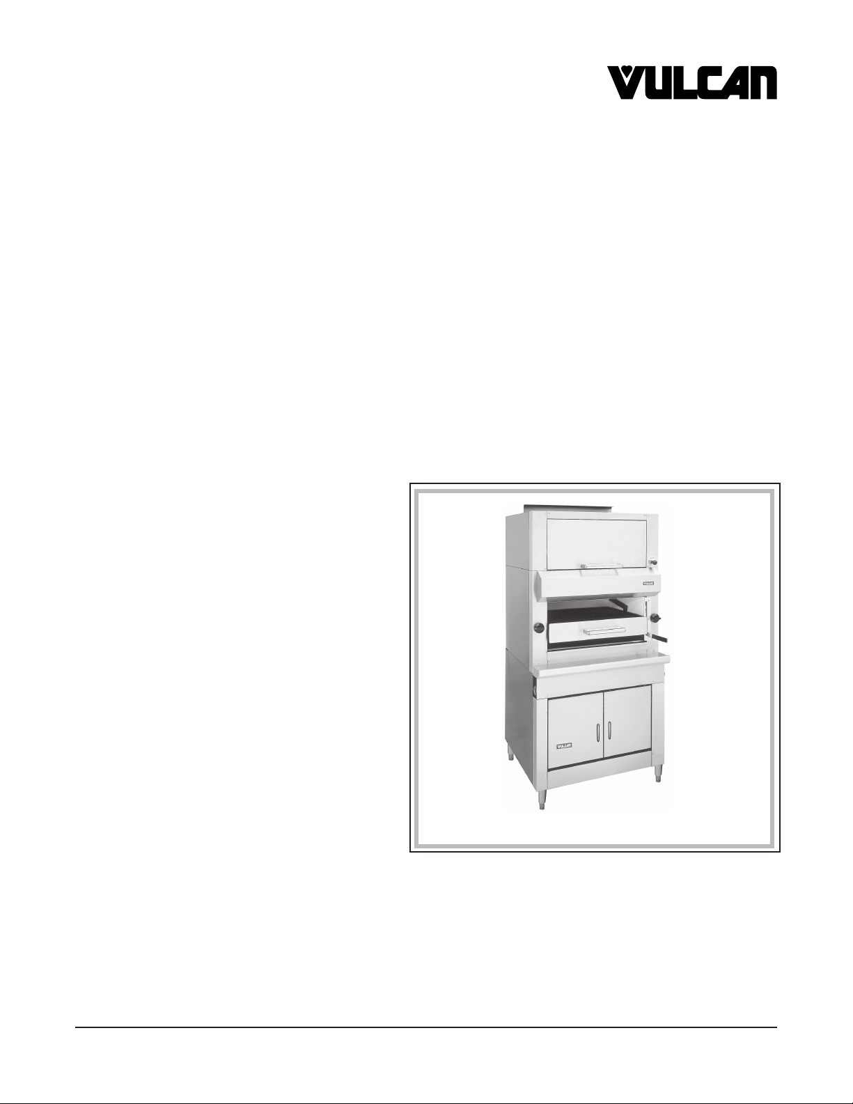
Model VIR36FS
VULCAN-HART COMPANY, P.O. BOX 696, LOUISVILLE, KY 40201-0696, TEL. (502) 778-2791
FORM 31168 (Jan. 2001) www.vulcanhart.com
– 1 –
Page 2

IMPORTANT FOR YOUR SAFETY
THIS MANUAL HAS BEEN PREPARED FOR PERSONNEL QUALIFIED TO INSTALL GAS
EQUIPMENT, WHO SHOULD PERFORM THE INITIAL FIELD START-UP AND
ADJUSTMENTS OF THE EQUIPMENT COVERED BY THIS MANUAL.
POST IN A PROMINENT LOCATION THE INSTRUCTIONS TO BE FOLLOWED IN THE
EVENT THE SMELL OF GAS IS DETECTED. THIS INFORMATION CAN BE OBTAINED
FROM THE LOCAL GAS SUPPLIER.
IMPORTANT
IN THE EVENT A GAS ODOR IS DETECTED, SHUT
DOWN UNITS AT MAIN SHUTOFF VALVE AND
CONTACT THE LOCAL GAS COMPANY OR GAS
SUPPLIER FOR SERVICE.
FOR YOUR SAFETY
DO NOT STORE OR USE GASOLINE OR OTHER
FLAMMABLE VAPORS OR LIQUIDS IN THE
VICINITY OF THIS OR ANY OTHER APPLIANCE.
WARNING
IMPROPER INSTALLATION, ADJUSTMENT,
ALTERATION, SERVICE OR MAINTENANCE CAN
CAUSE PROPERTY DAMAGE, INJURY OR DEATH.
READ THE INSTALLATION, OPERATING AND
MAINTENANCE INSTRUCTIONS THOROUGHLY
BEFORE INSTALLING OR SERVICING THIS
EQUIPMENT.
IN THE EVENT OF A POWER FAILURE, DO NOT
ATTEMPT TO OPERATE THIS DEVICE.
© VULCAN-HART COMPANY, 2001
– 2 –
Page 3

TABLE OF CONTENTS
GENERAL. . . . . . . . . . . . . . . . . . . . . . . . . . . . . . . . . . . . . . . . . . . . . . . . . . . . . . . . . . . . . . . . . . . . . . . 4
INSTALLATION . . . . . . . . . . . . . . . . . . . . . . . . . . . . . . . . . . . . . . . . . . . . . . . . . . . . . . . . . . . . . . . . . . 4
Unpacking . . . . . . . . . . . . . . . . . . . . . . . . . . . . . . . . . . . . . . . . . . . . . . . . . . . . . . . . . . . . . . . . . 4
Location . . . . . . . . . . . . . . . . . . . . . . . . . . . . . . . . . . . . . . . . . . . . . . . . . . . . . . . . . . . . . . . . . . 4
Installation Codes and Standards . . . . . . . . . . . . . . . . . . . . . . . . . . . . . . . . . . . . . . . . . . . . . . 5
Leveling . . . . . . . . . . . . . . . . . . . . . . . . . . . . . . . . . . . . . . . . . . . . . . . . . . . . . . . . . . . . . . . . . . 5
Gas Connections . . . . . . . . . . . . . . . . . . . . . . . . . . . . . . . . . . . . . . . . . . . . . . . . . . . . . . . . . . . 5
Testing the Gas Supply System . . . . . . . . . . . . . . . . . . . . . . . . . . . . . . . . . . . . . . . . . . . . . . . 6
Flue Connections . . . . . . . . . . . . . . . . . . . . . . . . . . . . . . . . . . . . . . . . . . . . . . . . . . . . . . . . . . . 6
OPERATION . . . . . . . . . . . . . . . . . . . . . . . . . . . . . . . . . . . . . . . . . . . . . . . . . . . . . . . . . . . . . . . . . . . . 7
Controls . . . . . . . . . . . . . . . . . . . . . . . . . . . . . . . . . . . . . . . . . . . . . . . . . . . . . . . . . . . . . . . . . . 7
Lighting Instructions . . . . . . . . . . . . . . . . . . . . . . . . . . . . . . . . . . . . . . . . . . . . . . . . . . . . . . . . . 7
Grid Position and Gas Setting . . . . . . . . . . . . . . . . . . . . . . . . . . . . . . . . . . . . . . . . . . . . . . . . 7
Preheating . . . . . . . . . . . . . . . . . . . . . . . . . . . . . . . . . . . . . . . . . . . . . . . . . . . . . . . . . . . . . . . . 7
Operating VRB36 Series Models . . . . . . . . . . . . . . . . . . . . . . . . . . . . . . . . . . . . . . . . . . . . . . 7
Operating VIR36 Series Models . . . . . . . . . . . . . . . . . . . . . . . . . . . . . . . . . . . . . . . . . . . . . . . 7
Shutdown . . . . . . . . . . . . . . . . . . . . . . . . . . . . . . . . . . . . . . . . . . . . . . . . . . . . . . . . . . . . . . . . . 7
Cleaning . . . . . . . . . . . . . . . . . . . . . . . . . . . . . . . . . . . . . . . . . . . . . . . . . . . . . . . . . . . . . . . . . . 8
MAINTENANCE . . . . . . . . . . . . . . . . . . . . . . . . . . . . . . . . . . . . . . . . . . . . . . . . . . . . . . . . . . . . . . . . . . 8
Lubrication . . . . . . . . . . . . . . . . . . . . . . . . . . . . . . . . . . . . . . . . . . . . . . . . . . . . . . . . . . . . . . . . 8
Pilot Lights . . . . . . . . . . . . . . . . . . . . . . . . . . . . . . . . . . . . . . . . . . . . . . . . . . . . . . . . . . . . . . . . 8
Vent. . . . . . . . . . . . . . . . . . . . . . . . . . . . . . . . . . . . . . . . . . . . . . . . . . . . . . . . . . . . . . . . . . . . . . 8
Recommended Service Frequency . . . . . . . . . . . . . . . . . . . . . . . . . . . . . . . . . . . . . . . . . . . . . 8
Service and Parts Information . . . . . . . . . . . . . . . . . . . . . . . . . . . . . . . . . . . . . . . . . . . . . . . . . 8
– 3 –
Page 4

INSTALLATION, OPERATION AND CARE OF
VRB AND VIR SERIES TOP FIRED BROILERS
PLEASE KEEP THIS MANUAL FOR FUTURE USE
GENERAL
Vulcan-Hart Broilers are produced with quality workmanship and material. Proper installation, usage
and maintenance of your broiler will result in many years of satisfactory performance.
It is suggested that you thoroughly read this entire manual and carefully follow all of the instructions
provided.
INSTALLATION
Before installing, verify that the type of gas supply (natural or propane) agrees with the specifications
on the rating plate located on the front left side of the broiler. If the supply and equipment requirements
do not agree, do not proceed with the installation. Contact your dealer or Vulcan-Hart Company
immediately.
UNPACKING
This broiler was inspected before leaving the factory. The transportation company assumes full
responsibility for safe delivery upon acceptance of the shipment. Immediately after unpacking, check
for possible shipping damage. If the broiler is found to be damaged, save the packaging material and
contact the carrier within 15 days of delivery.
Carefully unpack broiler and place in a work-accessible area as near to its final installed position as
possible.
LOCATION
The equipment area must be kept free and clear of combustible substances.
To install the broiler without legs on a non-combustible curb or platform, the front must extend 3" (7.6 cm)
beyond the curb or platform.
To install the broiler on a combustible floor, the 6" (15 cm) legs must be installed, and minimum side
and rear clearances of 6" (15 cm) from combustible construction and 0" from non-combustible
construction must be provided.
The installation location must allow adequate clearances for servicing and proper operation. A
minimum front clearance of 24" (61 cm) is required.
– 4 –
Page 5

Do not obstruct the flow of combustion and ventilation air. Adequate clearance for air openings into the
combustion chamber must be provided. Make sure there is an adequate supply of air in the room to
replace air taken out by the ventilating system. Do not permit fans to blow directly at the broiler. Avoid
wall-type fans which create air cross currents within the room. Avoid open windows next to the broiler.
INSTALLATION CODES AND STANDARDS
The broiler must be installed in accordance with:
In the United States of America:
1. State and local codes.
2. National Fuel Gas Code, ANSI-Z223.1 (latest edition). Copies may be obtained from The
American Gas Association, Inc., 1515 Wilson Blvd., Arlington, VA 22209.
In Canada:
1. Local codes.
2. CAN/CGA-B149.1 Natural Gas Installation Code (latest edition).
3. CAN/CGA-B149.2 Propane Installation Code (latest edition), available from The Canadian Gas
Association, 178 Rexdale Blvd., Etobicoke, Ontario, Canada M9W 1R3.
LEVELING
Place a carpenter's level inside the broiler. Level the broiler front to back and side to side. Unless the
broiler is level, it will not give proper cooking results.
GAS CONNECTIONS
CAUTION: Gas supply connections and any pipe joint compound must be resistant to the action
of propane gases.
Location of the gas inlet is on the lower rear right corner of the broiler. Codes require that a gas shutoff
valve must be installed in the gas line ahead of the broiler.
Connect gas supply to the broiler. Make sure the pipes are clean and free of obstructions.
Connection of Manifolds in a Battery: Two or more broilers can be coupled together at the manifold
by removing the front control panel to make necessary connections. Be sure to cap open ends. To
connect, adjust manifold by loosening U-bolts. In a large battery of eight or more units, the gas should
be fed from both ends of the battery. T gas connections can be installed whenever necessary for
increased gas supply.
For further details, consult your local gas company.
The top roll front may also be removed for your convenience.
– 5 –
Page 6

A gas pressure regulator suitable for the V Series Heavy Duty Range battery application or single unit
MUST be furnished by the installer or plumber at the time of installation. Connect the unit to 1
1
/4" pipe
or larger. Check rating plate(s) for proper gas, gas pressure, and total BTU input for each application.
The gas pressure regulator must have proper OUTLET PRESSURE and capacity for battery
application.
The warranty is void if the proper gas pressure regulator is not installed.
All model VIR burners and air shutters are of the fixed type and require no adjustments.
WARNING: PRIOR TO LIGHTING, CHECK ALL JOINTS IN THE GAS SUPPLY LINE FOR LEAKS.
USE SOAP AND WATER SOLUTION. DO NOT USE AN OPEN FLAME.
After piping has been checked for leaks, all piping receiving gas should be fully purged to remove air.
TESTING THE GAS SUPPLY SYSTEM
When gas supply pressure exceeds 1/2 psig (3.45 kPa), the broiler and its individual shutoff valve must
be disconnected from the gas supply piping system.
When gas supply pressure is 1/2 psig (3.45 kPa) or less, the broiler should be isolated from the gas
supply system by closing its individual manual shutoff valve.
FLUE CONNECTIONS
DO NOT obstruct the flow of flue gases from the flue located on the rear of the broiler. It is
recommended that the flue gases be ventilated to the outside of the building through a ventilation
system installed by qualified personnel.
From the termination of the flue to the filters of the hood venting system, a minimum clearance of 18"
(46 cm) must be maintained.
Information on the construction and installation of ventilating hoods may be obtained from the standard
for "Vapor Removal from Cooking Equipment," NFPA No. 96 (latest edition), available from The
National Fire Protection Association, Batterymarch Park, Quincy, MA 02269.
– 6 –
Page 7

OPERATION
WARNING: THE BROILER AND ITS PARTS ARE HOT. BE CAREFUL WHEN OPERATING,
CLEANING OR SERVICING THE BROILER.
CONTROLS
Gas Valves — Regulate gas flow to the burners.
Elevator Lever — Use elevator lever on the right to position the grill in relation to the burner heat.
Grease Drawer — Collects grease from broiled food.
LIGHTING INSTRUCTIONS
1. Turn the gas shut-off and gas valves to the OFF position and wait 5 minutes.
1
2. Turn gas shut-off valve ON and light two pilots with a lit taper. Adjust until the pilot flame is
(6 mm) high. The flame should have a slight yellow tip. Pilot valves are behind the plug button
on the right panel.
3. The only adjustment needed may be the air shutter located at the front face of the burner where
the orifice enters the venturi. Adjust all traces of yellow out of the burner flame.
/4"
4. To relight, follow steps 1-3.
GRID POSITION AND GAS SETTING
Each operator will find the optimum grid position and gas setting for various products; however, it is
recommended that gas input be reduced first when lower grid temperatures are desired. Further
reduction in grid temperatures, if necessary, can then be adjusted by lowering the grid position.
PREHEATING
Allow broiler to preheat approximately 30 minutes with burners full-on. Rub grates with grease before
using. The excess grease will run forward and drip onto the front grease drawer.
OPERATING VRB36 SERIES MODELS
1. Load broiler.
2. Turn gas valve to the left (counterclockwise) as far as the knob will go.
3. When the burner lights, turn the knob to the right (clockwise) until the flame is the desired height.
OPERATING VIR36 SERIES MODELS
1. Turn valves full ON to light.
2. Do not adjust lower than one-half flame.
SHUTDOWN
1. For complete shutdown, turn gas and shut-off valves to the OFF position.
2. Turn pilot adjustment valve fully closed until gas stops flowing.
– 7 –
Page 8

CLEANING (DAILY)
Allow broiler to cool.
Thoroughly scrape grill so that grease flows into grease drawer. This prevents flare-ups.
Soak grill overnight and rinse.
Remove and empty grease drawer. Wash, rinse, and dry with a soft clean cloth. Once broiler is clean,
replace grease drawer.
Clean stainless steel surfaces with a mild detergent and water, using a damp cloth, or with a
commercial stainless steel cleaner. Rinse thoroughly and wipe dry with a soft clean cloth.
Burner ports and throats should be thoroughly cleaned. Venturi must be free from grease and lint. DO
NOT insert pick in burner port hole.
MAINTENANCE
WARNING: THE BROILER AND ITS PARTS ARE HOT. BE CAREFUL WHEN OPERATING,
CLEANING OR SERVICING THE BROILER.
LUBRICATION
All moving parts must be checked for wear and lubricated. Contact your local Vulcan authorized
servicer.
PILOT LIGHTS
Pilot lights are to be kept clean and adjusted at the proper flame height.
VENT
Annually, when the broiler is cool, check the flue and clear any obstructions.
RECOMMENDED SERVICE FREQUENCY
Frequency of service maintenance will be largely dependent upon customer usage.
10-12 hours operation per day, 7 days a week — Every 30-60 days
4-6 hours a day, 5 days a week — Every 120 days
Limited daily usage — Every 180 days
All equipment — At least once a year
SERVICE AND PARTS INFORMATION
To obtain service and parts information concerning this broiler, contact the Vulcan-Hart Service
Agency in your area (refer to listing supplied with the broiler), or Vulcan-Hart Company Service
Department at the address or phone number shown on the front cover of this manual.
FORM 31168 (Jan. 2001) PRINTED IN U.S.A.
– 8 –
 Loading...