

Page 1
INSTALLATION & OPERATION MANUAL FOR
Hotplates
MODEL
VHP212 ML-135AHP-12
VHP424 ML-135AHP-24
VHP636 ML-135AHP-36
VHP848 ML-135AHP-48
www.vulcanhart.com
MLS
MODELS
MLS
AHP212 ML-135AHP-12
AHP424 ML-135AHP-24
AHP636 ML-135AHP-36
AHP848 ML-135AHP-48
www.wolfrange.com
ITW Food Equipment Group, LLC
3600 North Point Blvd.
Baltimore, MA 21222
AHP424
RETAIN THIS MANUAL FOR FUTURE USE
FORM F-36955 (04-07)
Page 2

IMPORTANT FOR YOUR SAFETY
THIS MANUAL HAS BEEN PREPARED FOR PERSONNEL QUALIFIED TO
INSTALL GAS EQUIPMENT, WHO SHOULD PERFORM THE INITIAL FIELD
START-UP AND ADJUSTMENTS OF THE EQUIPMENT COVERED BY THIS
MANUAL.
POST IN A PROMINENT LOCATION THE INSTRUCTIONS TO BE FOLLOWED IN
THE EVENT THE SMELL OF GAS IS DETECTED. THIS INFORMATION CAN BE
OBTAINED FROM THE LOCAL GAS SUPPLIER.
IMPORTANT
IN THE EVENT A GAS ODOR IS DETECTED, SHUT
DOWN UNITS AT MAIN SHUTOFF VALVE AND
CONTACT THE LOCAL GAS COMPANY OR GAS
SUPPLIER FOR SERVICE.
FOR YOUR SAFETY
DO NOT STORE OR USE GASOLINE OR OTHER
FLAMMABLE VAPORS OR LIQUIDS IN THE VICINITY OF
THIS OR ANY OTHER APPLIANCE.
WARNING: IMPROPER INSTALLATION, ADJUSTMENT,
ALTERATION, SERVICE OR MAINTENANCE CAN
CAUSE PROPERTY DAMAGE, INJURY OR DEATH.
READ THE INSTALLATION, OPERATING AND
MAINTENANCE INSTRUCTIONS THOROUGHLY BEFORE
INSTALLING OR SERVICING THIS EQUIPMENT.
IN THE EVENT OF A POWER FAILURE, DO NOT
ATTEMPT TO OPERATE THIS DEVICE.
- 2 -
Page 3

INSTALLATION, OPERATION AND CARE OF
GAS COUNTERTOP HOTPLATE RANGE
GENERAL
Gas Countertop Hotplates are designed for commercial use only and feature fast, efficient
gas heat. Each burner is controlled by an adjustable gas valve. Cast grates and burners
are easily removed for cleaning when cool .
Model
AHP212 / VHP212 2 60,000 45,000 (30,000 + 15,000)
AHP424 / VHP424 4 120,000 90,0 00 (60,000 + 30,000)
AHP636 / VHP636 6 180,000 135,000 (90,000 + 45,000)
AHP848 / VHP848 8 240,000 180,000 (120,000 + 60,000)
# of
Burners
BTU/hr Input Rating
Standard & Step-Up
BTU/hr Input Rating
Half Hot-Top
INSTALLATION
UNPACKING
Immediately after unpacking, check for possible shipping damage. If the hotplate is found
to be damaged, save the packaging material and contact the carrier within 15 days of
delivery.
Before installing, verify that the unit model and t ype of gas supply (natural gas or
propane) agree with the specifi cations on the rating plate riveted to th e right side of the
unit in the upper front corner. If the supply and equipment requirements do not agree, do
not proceed with the installation. Cont act your dealer immediately.
LOCATION
The installation location must be kept free and clear of combustibles. Do not obstruct the
flow of combustion and ventilation air. DO NOT install the hotplate adjacent to open
burners or fryers.
Sufficient air should be allowed to enter the room to compensate for the amount of air
removed by any ventilating system and for combustion of the gas burners. Do not
obstruct the air flow into and around the hotplate. Position the hotplate in its final
location. Check that there are sufficient clearances to service the hotplate and to make
the required gas supply connection(s). Provide 24" clearance at the front for cleaning,
maintenance, service and proper operation.
Minimum clearances to combustible construction are 6" to the back and 6" to the sides.
Minimum clearances to non-combus tible walls are 0" to the rear and 0" to the sides.
- 3 -
Page 4

INSTALLATION CODES AND STANDARDS
The hotplate must be installed in a ccordance with:
In the United States of America:
1. State and local codes.
2. National Fuel Gas Code, ANSI-Z223.1/NFPA #54 (latest edition). This shall incl ude but
not be limited to: NFPA #54 Section 10.3.5.2 for Venting. Copies may be obtained
from The American Gas Association Accredited Standards Committee Z223, @ 400
N. Capital St. NW, Washington, DC 20001 or the Secretary Standards Council, NFPA,
1 Batterymarch Park Quincy, MA 02169-7471
NOTE: In the Commonwealth of Massachusetts
All gas appliances vented through a ventilation hood or exhaust system equipped with
a damper or with a power means of exhaust shall comply with 248 CMR.
3. NFPA Standard # 96 Vapor Removal from Cooking Equipment, latest edition, availabl e
from the National Fire Protection Associa tion, Batterymarch Park, Quincy, MA 02269.
In Canada:
1. Local codes.
2. CAN/CSA-B149.1 Natural Gas Installation (latest edition)
3. CAN/CSA-B149.2 Propane Installation Code (latest edition), available from the
Canadian Gas Association, 178 Rexdale Blvd. , Etobicoke, Ontario, Canada M9W 1R3
CASTER EQUIPPED APPLIANCES
Hotplates mounted on stands with casters must use a flexible connector (not supplied)
that complies with the Standard for Connec tors for Movable Gas Appliances, ANSI Z21.69
• CSA 6.16 and a quick-disconnect device that complies with the Standard for Quick-
Disconnect Devices for use With Gas Fuel, ANSI-Z21.41 • CSA 6.9. In addition, adequate
means must be provided to limit movement of the hotplate without depending on the
connector and the quick-disconnect device or its associated piping to limit hotplate
movement. Attach the restraining device at the rear of the hotplate. If disconnection of
the restraint is necessary, turn off the gas supply before disconnection. Reconnect the
restraint prior to turning the gas supply on and return the hotplate to its installation
position.
If the Hotplate is installed on casters and is moved for any reason, it is recommended
that it be re-leveled (see LEVELING).
LEVELING
If the hotplate is equipped with legs or is mounted on the optional stand equipped with
legs, turn the feet at the bottom of the legs in or out to level the hotplate in the final
installed location. If the ho tplate is mounted on the optional stand equi pped with casters,
position the hotplate on a level floor.
VENTILATION HOOD
The hotplate should be installed unde r a suitable ventilation hood. For safe operation and
proper ventilation, keep the space between the hotplate and vent hood free from any
obstructions.
- 4 -
Page 5
GAS CONNECTION
The data plate on the right side, in the upper front corner of the appliance indicates the
type of gas your unit is equipped to burn. DO NOT connect to any other gas type.
CAUTION: All gas supply connections and any pipe joint compound must be
resistant to the action of propane.
Purge the supply line to clean out any dust, dirt, or any foreign matter before connecting
the line to the unit.
Codes require that a gas shut-off valve be installed in the gas line ahead of the
appliance. The gas supply line must be at least the equivalent of ¾” iron pipe.
An adequate gas supply is necessary. Undersized or low pressure lines will restrict the
volume of gas required for satisfactory performance. A minimum supply pressure of 7"
W.C. for natural gas and 11" W.C. for propane gas is recommended. With all units
operating simultaneously, the manifold pressure on all units should not show any
appreciable drop.
When testing the gas supply piping system, if test pressures exceed ½ psig (3.45 kPa),
the appliance and its individual shutoff valve must be disconnected from the gas supply
piping system. When test pressures are ½ psig (3.45 kPa) or less, the appliance must be
isolated from the gas supply piping system by closing its individual manu al shut-off valve
during any pressure testing of the system.
WARNING: PRIOR TO LIGHTING, CHECK ALL JOINTS IN THE GAS SUPPLY LINE FOR
LEAKS. USE SOAP AND WATER SOLUTION. DO NOT USE AN OPEN FLAME.
GAS PRESSURE REGULATOR INSTALLATION
Gas regulator pressure is preset at 5” Water Column (W.C.) for natural gas, and 10” W.C.
for propane gas. Minor ad justments may be required bas ed on site specific gas pressure .
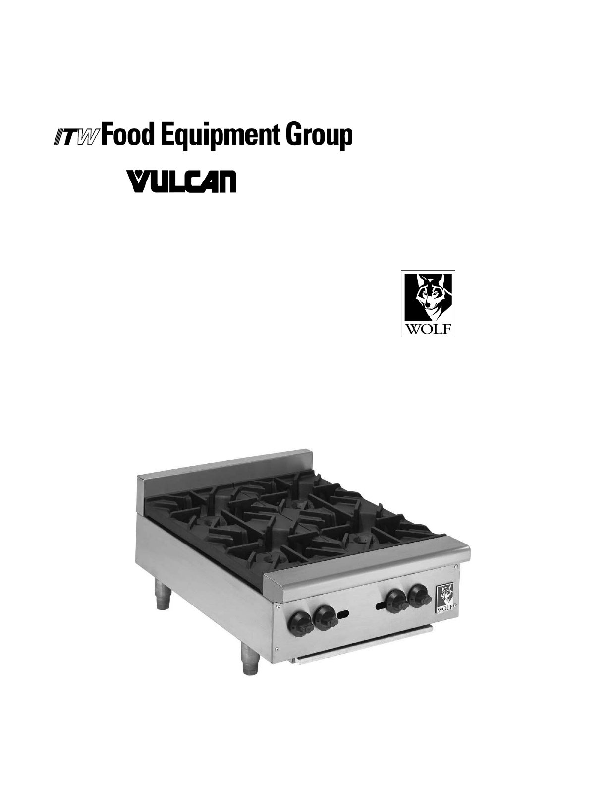
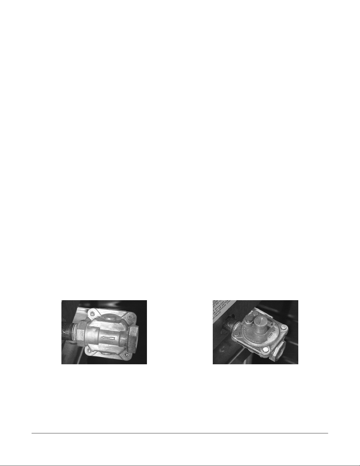
Install the regulator as close to the hotplate on the gas suppl y line as possible. Make sure
that the arrow on the underside of the regulato r is oriented in the direction of gas flow to
the hotplate (Fig. 2) and the regulator is positioned with the vent plug and adjustment
screw upright (Fig. 3).
Fig. 2
Fig. 3
The minimum supply pressure (upstream of the regulator) should be 7-9” W.C. for natural
gas and 11-12” W.C. for propane gas. At no time should the hotplate be connected to
supply pressure greater than ½ psig (3.45 kPa ) or 14” W.C.
- 5 -
Page 6

OPERATION
WARNING: THE HOTPLATE AND ITS PARTS ARE HOT. USE CARE WHEN
OPERATING, CLEANING, OR SERVICING THE APPLIANCE.
LIGHTING INSTRUCTIONS
1. Turn gas shutoff valve and burner valve to the OFF position and wait 5 minutes.
2. Turn gas shutoff valve ON. Light the pilot adjacent to each main burner. Adjust the
pilot valve screw until the pilot flame has a slight ye llow tip.
3. After the pilot has been established, turn the burner valve to the ON position. The
burner flames may be adjusted, using the air shutters located behind the louvered
panel in the front of the broiler below the burner valve.
4. If the burners fail to light, turn off all valves, wait 5 minutes and repeat steps 1-3.
5. To shut down, turn the burner valves to the OFF position.
CLEANING
Grates may be immersed in commercial cleaning compound overnight. In the morning,
rinse with hot water to re move any residues of cleaning compound.
Burner ports and burner rest should be thoroughly cleaned. Venturi must be free from
grease and lint. When clea ning, do not insert a pick into the burner p ort holes – soap and
water will normally do the job. Heavy spattering or spill-over may require cleaning with a
mild oven cleaner. After cleaning, rinse wit h clean water and dry with a dry cloth. Be sure
to apply a thin coat of oil fo r protection after cleaning.
Stainless steel surfaces may be cleaned using damp cloth with mild detergent and water
solution.
Places where fat, grease, or food can accumulat e must be cleaned regularly.
MAINTENANCE
WARNING: THE HOTPLATE AND ITS PARTS ARE HOT. USE CARE WHEN
OPERATING, CLEANING, OR SERVICING THE HOTPLATE.
VENT SYSTEM
At least twice a year the exhaust h ood (venting system) should be exam ined and cleaned.
SERVICE
Contact your local Service Agency for any repairs or adjustments needed on this
equipment.
- 6 -
 Loading...