

Page 1
OPERATOR`S MANUAL
ELECTRIC WINCH
WARNING
DO NOT INSTALL, USE OR REPAIR THIS EQUIPMENT BEFORE READING THIS
MANUAL IN ITS ENTIERETY. FAILURE TO READ AND FOLLOW THE INSTRUCTIONS
DESCRIBED IN THIS MANUAL COULD RESULT IN SERIOUS INJURY, DEATH AND/OR
MATERIAL DAMAGES.
Page 2

WARNING
The equipment described in this manual is not designed to lift or move
people nor to lift or move loads over people and must therefore not be used for
such means.
WARNING
Before putting the equipment described in this manual into service, it is
strongly recommended to familiarize oneself with the sections on using,
inspecting and maintaining lifting equipment in the standards CSA B167
Overhead cranes, gantry cranes, monorails, hoists and jib cranes and ASME B30.7
Winches. To ensure a safe work environment, each worker must be trained in
the equipment`s basic principles of operation and proper operating procedures.
DANGER
High voltages are used and present inside the enclosure and across the
conductors of this equipment. Before performing any kind of mechanical or
electrical maintenance, the machine must be disconnected from the power
source and locked out/tagged out according to applicable standards. Refer to
ANSI Z244.1 Personal Protection – Lockout/Tag out of Energy Sources for
additional details.
Page 3

Contents
Technical Specifications ............................................................................ 4
General Dimensions .............................................................................. 4
Working Loads....................................................................................... 5
Unpacking ................................................................................................. 6
Installation ................................................................................................ 7
Footprint ............................................................................................... 7
Gear Reducer Orientation and Lubrication ........................................... 8
Winding of the Wire Rope .................................................................... 9
Electrical Connections ............................................................................. 10
Using the Equipment............................................................................... 13
Inspection ................................................................................................ 16
Daily Inspection ................................................................................... 16
Periodic Inspection .............................................................................. 17
Inspection Log Book ............................................................................ 18
Hook Measuring and Discard Criteria ................................................. 18
Wire Rope Discard Criteria .................................................................. 19
Maintenance ........................................................................................... 20
Gear Reducer Lubrication ................................................................... 20
Vent Plug and Level Plug ................................................................. 20
Recommended Oil Types ................................................................ 21
External Use ........................................................................................ 21
Operating Environment ...................................................................... 21
Part List ................................................................................................... 22
Page 4
Operator`s Manual – Electric Winch 4 2018-08-03, rev 1
Technical Specifications
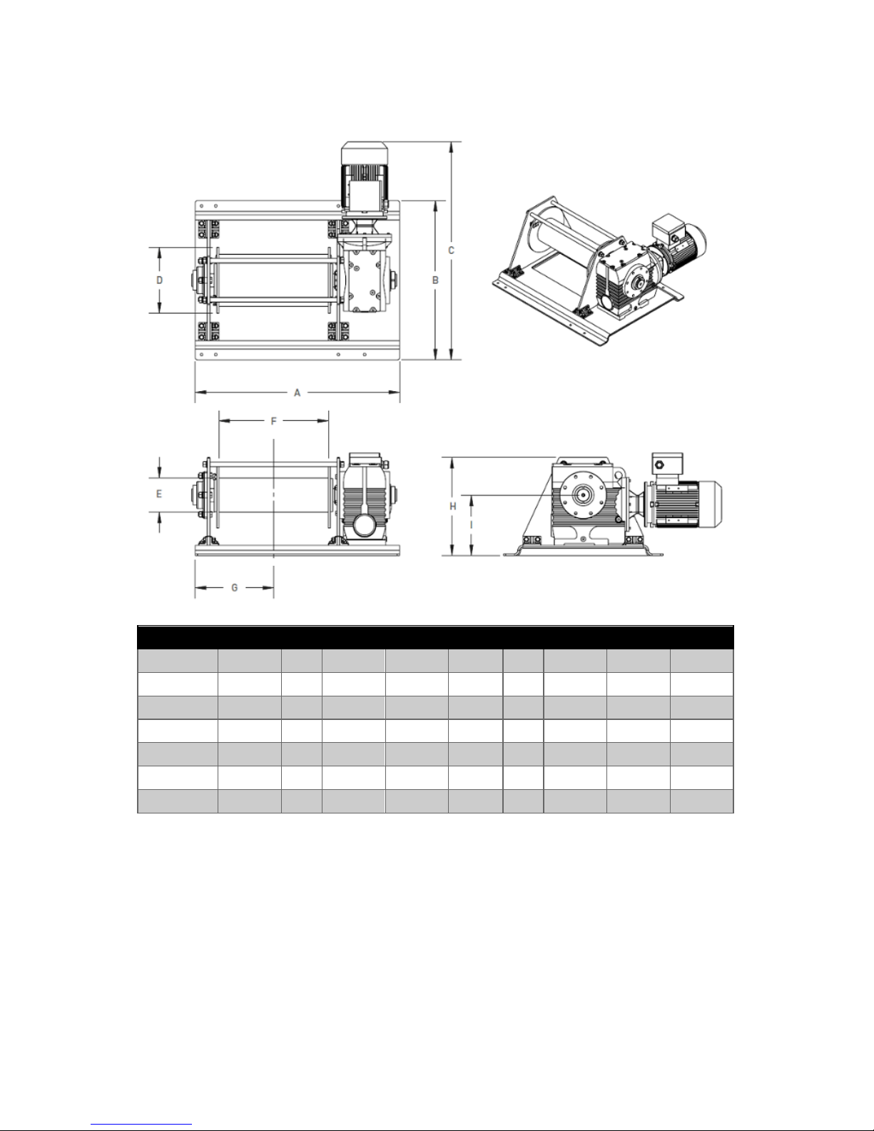
General Dimensions
General Dimensions
Model
A B C D E F G H I
W047
29.88
21
27.00
5.75
3.38
16
13.18
9.69
6.18
W057
38.38
22
28.50
6.63
3.75
24
17.18
10.63
5.63
W067
39.38
23
29.88
7.38
3.75
24
17.18
12.25
7.75
W077
41.38
28
35.50
9.38
4.75
24
17.18
14.88
9.38
W087
42.88
30
39.63
11.25
5.75
24
17.18
17.50
11.13
W097
44.88
35
48.00
14.50
7.50
24
17.18
21.50
13.25
For non-standard and custom models, consult the drawings supplied with the
equipment.
Page 5
Operator`s Manual – Electric Winch 5 2018-08-03, rev 1
Working Loads
Limits for Hauling/Pulling
Model
Wire Rope (in)
Wire Rope (ft)
/ Layer
HP
1
Weight
(lb)
2
1
st
Layer
2
nd
Layer
3
rd
Layer
4
th
Layer
W047
1/8
115
.75
195
550 lb
22 fpm
500 lb
23.5 fpm
475 lb
25.5 fpm
450 lb
27 fpm
W057
3/16
130
1.5
290
900 lb
25 fpm
850 lb
27.5 fpm
750 lb
29.5 fpm
700 lb
32 fpm
W067
1/4
100
2
330
1650 lb
18.5 fpm
1450 lb
20.5 fpm
1300 lb
23 fpm
1200 lb
25.5 fpm
W077
5/16
100
3
510
2800 lb
13.5 fpm
2700 lb
15.5 fpm
2400 lb
17 fpm
2200 lb
18.5 fpm
W087
3/8
100
5
710
4100 lb
16 fpm
4100 lb
18 fpm
3800 lb
20 fpm
3400 lb
21.5 fpm
W097
1/2
100
7.5
1250
7000 lb
15.5 fpm
6200 lb
17.5 fpm
5600 lb
19.5 fpm
5100 lb
21.5 fpm
Limits for Lifting
W047
1/8
115
.75
195
400 lb
22 fpm
400 lb
23.5 fpm
400 lb
25.5 fpm
400 lb
27 fpm
W057
3/16
130
1.5
290
800 lb
25 fpm
800 lb
27.5 fpm
750 lb
29.5 fpm
700 lb
32 fpm
W067
1/4
100
2
330
1400 lb
18.5 fpm
1200 lb
20.5 fpm
1050 lb
23 fpm
950 lb
25.5 fpm
W077
5/16
100
3
510
1900 lb
13.5 fpm
1900 lb
15.5 fpm
1900 lb
17 fpm
1850 lb
18.5 fpm
W087
3/8
100
5
710
2800 lb
16 fpm
2800 lb
18 fpm
2800 lb
20 fpm
2600 lb
21.5 fpm
W097
1/2
100
7.5
1250
5400 lb
15.5 fpm
4800 lb
17.5 fpm
4350 lb
19.5 fpm
3950 lb
21.5 fpm
ATTENTION
The specifications above are based on the recommended wire rope
cable. Changing the size or the construction of the wire rope will affect the
performance of the machine and the working loads would have to be
recalculated.
1
Motor HP may vary with the application and certain options
2
Excluding control enclosure and cable weights; may vary for certain options
Page 6
Operator`s Manual – Electric Winch 6 2018-08-03, rev 1
ATTENTION
The wire rope capacity depends on the rolling tension and the
distribution of the wire rope over the drum. The actual capacity may be 25-30%
below the specified length due to uneven winding of the wire rope or
crisscrossing of the wire rope
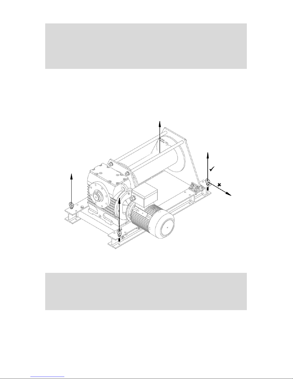
Unpacking
Some models are equipped with lifting lugs to facilitate manipulation of the
equipment during the installation. Never load the lugs sideways.
ATTENTION
Any lugs and additional bolt holes serve to help maneuver the
equipment during installation. Never use these holes or lugs to support a part or
the entirety of the load.
Page 7

Operator`s Manual – Electric Winch 7 2018-08-03, rev 1
Installation
Footprint
Winch Footprint
Model
Anchor Bolts
A B J K W047
4
29.88
21
19.13
21.83
W057
4
38.38
22
20.13
30.40
W067
4
39.38
23
21.38
30.73
W077
8
41.38
28
26.13
4.23
W087
8
42.88
30
28.13
4.97
W097
8
44.88
35
32.63
5.76
WARNING
Always use the recommended number of anchor bolts (dia. ½, grade 5
or higher) to fix the winch to the floor or the supporting structure. Failure to do
so may damage the equipment and/or the supporting structure.
DANGER
It is the user`s responsibility to ensure the floor and/or the supporting
structure can safely carry the working loads with an appropriate factor of safety.
The deflection of the structure must be negligible under the working load. Failure
to respect these recommendations may damage the equipment and/or the
supporting structure.
Page 8
Operator`s Manual – Electric Winch 8 2018-08-03, rev 1
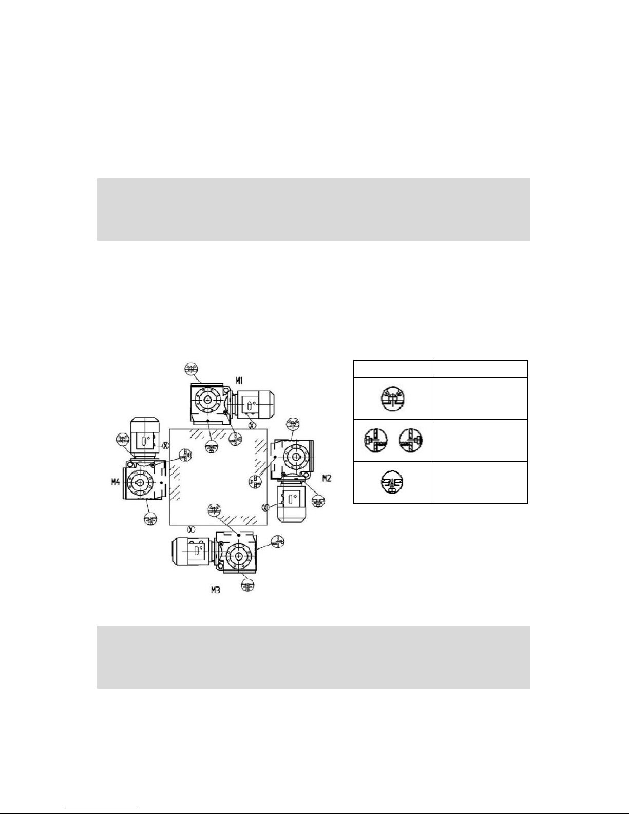
Gear Reducer Orientation and Lubrication
It is important to always maintain an adequate level of gear oil for the size and
orientation of the reducer. Unless otherwise specified, the reducer is filled for
horizontal use. Consult the maintenance section for recommended gear oil types
and amounts.
WARNING
Low oil level may result in premature wear of the gears. Consult the
maintenance section for the recommended oil types and amounts.
The reducer is always shipped with standard plugs to prevent oil from leaking
during transportation. The client must install the vent plug according to the
reducer orientation before putting the winch into service. The vent plug is
supplied in a plastic bag taped to the reducer.
Symbol
Definition
Vent plug
Level plug
Drain plug
*make sure the vent plug is
always on the top side to
ensure no leakage during the
use or the transportation of
the equipment
WARNING
Failure to install the vent plug may result in pressure built-up as the
reducer heats up causing the seals the blow out and spill the oil.
Page 9

Operator`s Manual – Electric Winch 9 2018-08-03, rev 1
Winding of the Wire Rope
WARNING
The wire rope must always be installed on the drum in a way that allows
it to come out from underneath the drum as indicated on the diagram below:
Page 10

Operator`s Manual – Electric Winch 10 2018-08-03, rev 1
Electrical Connections
WARNING
If the motor rotation is reversed some options (like the limit switches)
will not function properly which may lead to injury or equipment damage.
All electric connections must be performed by a qualified electrician. Do
not neglect to verify the current draw and the length of the power cable.
Improper connections or conductor sizing may cause the winch to overheat even
with no load.
The winch must be connected to the power source such that the motions
correspond to the indications on the control pendant, in other words the IN
button makes the wire rope wind on the drum where as the OUT button unwinds
the wire rope. The connection procedure steps are illustrated on the next page.
Page 11

Operator`s Manual – Electric Winch 11 2018-08-03, rev 1
WARNING
Never change the wiring in the control pendant to reverse the motions,
options like limit switches will not function properly.
Page 12

Operator`s Manual – Electric Winch 12 2018-08-03, rev 1
ATTENTION
Never connect 115V single phase motors in a standard household
socket. Even tough some models may work; household circuits are not sized for
such applications and the winch may interfere with other devices on the circuit.
Always consult a qualified electrician when connecting industrial equipment to
the electrical grid.
Check the voltage at the machine. The voltage should remain within ±5% of the
motor`s nominal voltage when the winch runs at full load.
Signs of Inadequate Wiring or Power Source
Rumbling or buzzing coming from the brake, motor or contactors
Flickering of lights wired to the same circuit as the winch
Excessive heating of the motor, internal components, electric conductors or
connectors
Motor stalls easily and cannot lift/pull the working load
Fuses burn often, or breakers trigger frequently
WARNING
Even though some models are equipped with thermal relays to protect
motors from overheating or from phase loss, it is the responsibility of the client
to ensure the equipment is wired to the electric grid in accordance with
applicable laws and electric standards and the means of disconnecting and
protecting the equipment from overcurrent are adequately sized.
Page 13

Operator`s Manual – Electric Winch 13 2018-08-03, rev 1
Using the Equipment
Before using any industrial equipment, the operator must be instructed on how
to use the equipment, how to stop the equipment in the event of an emergency
and how to identify, avoid and prevent risk situations. Before starting the
machine, the operator must ensure the maneuver can be performed safely (ex.:
the equipment is in order, the lift path is clear, the load will not go over other
workers, etc.). When using the machine, the operator must remain alert and
monitor the surrounding environment for arising dangers and, if a danger arises,
stop the equipment in a safe manner.
WARNING
The misuse of the winch can be very dangerous and could lead to
serious injury, death and/or property damage. To avoid risk situations, the
operator must know and follow the proper procedures described in this section.
DANGER
The winches can develop forces larger than the working load limits. It is
the operator`s responsibility to ensure the load never exceeds the working load
limit for the corresponding wire rope layer.
DANGER
All winches for lifting applications are always equipped with a brake
motor. Never use a winch without a brake motor to lift loads or pull them over a
steep slope where the load would be in danger of sliding or rolling down.
Page 14

Operator`s Manual – Electric Winch 14 2018-08-03, rev 1
ATTENTION
Never exceed a fleet angle of ±2° as indicated in the image below:
Dangerous Practices to be Avoided
DO NOT use a damaged, broken or otherwise malfunctioning winch
DO NOT use a winch before having read and understood the operator`s
manual
DO NOT use a winch that has been modified without the written approval
of the manufacture or a qualified engineer
DO NOT lift or pull more than the working load limit
DO NOT use the winch if the wire rope is twisted, pinched, damaged or
shows signs of excessive wear
DO NOT use a winch to lift, support or otherwise move people
DO NOT lift loads over people
DO NOT use a winch if people are not at a safe distance from the load or the
machine and remain at a safe distance throughout the whole maneuver
DO NOT attempt to lengthen or repair a damaged or broken wire rope
DO NOT use the wire rope as a sling or wrap it around the load in a choke
DO NOT lift with the tip of the hook or over the safety latch
DO NOT lift the load if with the weight is not evenly distributed across all
wire rope lines that pass through the pulley
DO NOT use the wire rope as an electric ground
DO NOT allow a welding electrode to touch the wire rope or the hook
DO NOT remove or modify the cautionary labels on the winch
DO NOT use a winch whose nameplate or safety and warning labels are
missing or illegible
DO NOT shock load the winch
DO NOT let an unqualified person to adjust or repair the equipment
DO NOT jog the load with the winch
Page 15

Operator`s Manual – Electric Winch 15 2018-08-03, rev 1
Recommended Practices
Inspect the winch at the beginning of each work shift. See Daily Inspection
for details
Protect the wire rope from weldment splashes and other contaminants
Be familiar with all the equipment`s functions and safety procedures
Turn off/lock out/tag out any malfunctioning equipment and inform the
person in charge as soon as possible
Make sure the limit switches (if applicable) function properly
Signal your intent to move a load to people around you
Signal the approach of a load to people around you
Keep both feet firmly on the floor while using the equipment
Use the safety latches on the hooks to prevent any below the hook
accessories from accidentally falling off
Ensure the entire path of the load is clear before moving the load
Make sure the hook moves in the same direction as indicated on the control
pendant
Inspect the hook regularly, replace damaged or worn parts and keep a
detailed register of all repairs made
Replace damaged or worn parts only with components from the original
manufacturer
Make sure the safety latches are closed before lifting a load and they do not
carry any part of the load
Do not shake the load when suspended on the hook
WARNING
The wire rope clamps on the drum are not designed to carry the full
load of the winch. You must always keep a minimum of 5 well tensioned wire
rope turns on the drum before moving a load.
Page 16

Operator`s Manual – Electric Winch 16 2018-08-03, rev 1
Inspection
Daily Inspection
The operator must conduct a daily inspection on the equipment at the beginning
of each shift or when the winch is used for the first time during the shift. The
daily inspection is a visual and auditory examination of the machine. The
following procedures should be carried out with no load:
Daily Inspection
1
Make sure the equipment is not tagged out of service
2
Make sure all functions work properly (up/down, emergency stop, horn,
etc.) and they agree with the indications on the control pendant
3
Check if the braking distance is normal
4
Check the hook for damage like cracks, grooves, excessive opening,
wear, torsion or other
5
Make sure the safety latch is present and closes/opens properly
6
Check the wire rope for signs of excessive wear like distortion, bird cages,
crushed sections, pinched sections, displaced or exposed core cable or
other
7
Check the wire rope for rust
8
Check the wire rope cable for broken wires; note the number and
distribution of the broken wires
9
Test the operation of all travel limiting devices
10
Check for oil leaks around and underneath the winch
11
Check if the winch makes any irregular or unusual noises during
operation
12
Make sure all nameplates and safety labels are present and legible
13
Check for broken, loose or missing structural components like fasteners,
brackets, link, anchors and others
Page 17

Operator`s Manual – Electric Winch 17 2018-08-03, rev 1
Periodic Inspection
An in-depth inspection of the equipment must be carried out on a regular basis
by a qualified person. The winch and its components are examined to ensure the
equipment is safe for use. The periodic inspections vary in frequency and details
according to the intensity of the equipment use but must include at least the
daily inspection procedure and a verification of the items listed below:
Periodic Inspection
1
Low oil level
2
Loose or missing bolts, nuts or rivets
3
Excessive gear backlash (should not be perceptible by the naked eye)
4
Signs of wear, corrosion, cracks or distortion on the winch components
such as, but not limited to: pulleys, bearings, chassis, drum, drum
flanges, anchor bolts, wire rope clips, shackles, bolts, shafts, gears, etc.
5
Wear or damage to the hook, see Hook Measuring and Discard Criteria
for details
6
Excessive wear of the wire rope drum
7
Cracked welds
8
Signs of heat damage, distortion, contamination or wear on the electric
and mechanical components of the brake
9
Excessive brake opening – readjust or replace brake disc according to
wear. Consult the brake manufacturer or Vulcan Hoist for details
10
Signs of pitting or other deterioration of the contact points on the
electric contactors
11
Problems with the normal use of the control buttons
12
Damaged electric wire insulation
13
Malfunction of heating elements (if applicable) on the reducer, motor,
brake, etc.
14
Inconsistent operation or poor reliability of the travel limiting devices (if
applicable)
15
Damage to the supporting structure or cracks in the concrete below the
winch
16
Damaged or missing nameplate
17
Missing or illegible safety labels
18
Wire rope cable showing signs of excessive wear such as, but not limited
to: wear, distortion, bird cages, crushed sections, pinched sections,
displaced or exposed wire rope core, corrosion. For more details, consult
Wire Rope Discard Criteria
Page 18

Operator`s Manual – Electric Winch 18 2018-08-03, rev 1
As a rule of thumb (unless indicated otherwise), replace any component whose
wear on any one dimension exceed 2.5% of the original nominal value.
Inspection Log Book
A detailed log book must be kept of all inspections, repairs and modifications
carried out on the equipment as well as a follow up on the wear of major
components like the wire rope cable, the hook, the gear reducer, the drum, etc.
These reports must be conserved for future reference and easily accessible to
members of the inspection, maintenance and repair crews.
Hook Measuring and Discard Criteria
It is recommended to replace any hook showing one or more of the following
signs of wear:
Hook Discard Criteria
1
Missing or illegible working load limit identification
2
Pitting, corrosion, cracks, grooves or deep lines on the hook body
3
Signs of weld or heat damage on the hook body, shank or swivel block
4
Wear on any dimension of the hook body exceeding 10% of the original
value
5
Permanent deformation of the hook opening exceeding 5% of the original
value
ATTENTION
It is the user`s responsibility to measure and record the initial hook
dimensions for future reference, since the shape and exact dimensions of the
hooks vary slightly from one hook to the other.
WARNING
If the hook opening exceeds the acceptable limits replace the hook. DO
NOT attempt to close the hook. The hook strength will be lowered.
Page 19

Operator`s Manual – Electric Winch 19 2018-08-03, rev 1
Wire Rope Discard Criteria
The precise discard criteria for the wire rope must be determined by a qualified
person while keeping in mind the characteristics of the application. As a rule of
thumb, any cable that shows one or more of the signs below should be replaced:
Wire Rope Discard Criteria
1
Six random broken wires over one cable lay or three broken wires in the
same strand over one cable lay
2
One broken wire close to an end fitting or a connector (bell fitting, spelter,
etc.)
3
One broken wire from the wire rope core which protrudes or loops out
from the wire rope structure
4
Sharp bends, crushed sections, bird cages or any other sign of damage
that results in severe distortion of the wire rope structure
5
Signs of heat damage (characteristic color change for example)
6
Reduction of the nominal diameter of 5% or more
Page 20

Operator`s Manual – Electric Winch 20 2018-08-03, rev 1
Maintenance
A log book of maintenance procedures, inspections findings and all repairs
carried out on the equipment must be kept for future reference.
Gear Reducer Lubrication
Vent Plug and Level Plug
Install the bent plug according to the reducer orientation before putting the
machine into service:
Symbol
Definition
Vent Plug
Level Plug
Drain Plug
*make sure the vent plug is
always on the top side to
ensure no leakage during the
use or the transportation of
the equipment
A minimum level of oil must be maintained to ensure proper gear lubrication:
Reducer Orientation and Oil Amounts
Reducer
M1 (L)
M2 (L2)
M3 (L)
M4 (L)
47
0.4
0.8
0.9
1.0
57
0.5
1.1
1.5
1.5
67
1.0
2.0
2.6
2.9
77
1.8
3.9
5.0
5.8
87
3.8
7.4
8.7
10.8
97
7.0
14.0
16.0
20.5
Page 21

Operator`s Manual – Electric Winch 21 2018-08-03, rev 1
Change the oil after the first 6 months then once every two years or more
frequently based on the use intensity
• Discard the old oil in accordance with local laws and regulations
• Do not mix different oil types inside the reducer. Certain oils may react
and affect the functionality of the reducer or damage the gears
Recommended Oil Types
Temperature
Grade
-30 à 15°C
ISO VG 150 or equivalent
-15 à 3°C
ISO VG 220 or equivalent
-3 à 23°C
ISO VG 320 or equivalent
23 à 40°C
ISO VG 460 or equivalent
40 à 80°C
ISO VG 680 or equivalent
Unless indicated otherwise, reducers are filled with Meropa 320 gear lubricant
External Use
In the case of external use, the winch must be covered and protected from rain
at all time. The risk of corrosion is increased further if high concentrations of salt
and/or humidity are present in the air. For such applications it may be necessary
to perform additional inspections and lubricate components more frequently.
Operating Environment
Unless indicated otherwise, the winch does not meet the requirements for the
following operating environments and must not be used in those environments:
• Prolonged exposure to temperatures below -20°C
• Presence of explosive gasses or vapours
• Presence of volatile solvents
• High concentration of dust or particulate matter
• Acidic or otherwise highly corrosive environment
Page 22

Operator`s Manual – Electric Winch 22 2018-08-03, rev 1
Part List
Page 23

Operator`s Manual – Electric Winch 23 2018-08-03, rev 1
Part List
Ref
Description
Part No.
W047
Qty
Part No.
W057
Qty
Part No.
W067
Qty
Part No.
W077
Qty
Part No.
W87
Qty
Part No.
W097
Qty
1
Reducer
WCH-100-4
1
WCH-100-57
1
WCH-100-67
1
WCH-100-77
1
WCH-100-87
1
WCH-100-97
1
2
Motor
1 1 1 1 1
1 3 Drum
WCH-A002-47
1
WCH-A002-57
1
WCH-A002-67
1
WCH-A002-77
1
WCH-A002-87
1
WCH-A002-97
1
4
Winch Base
WCH-004-47
1
WCH-004-57
1
WCH-004-67
1
WCH-004-77
1
WCH-004-87
1
WCH-004-97
1
5
Side Plate
WCH-007-47M
1
WCH-007-57M
1
WCH-007-67M
1
WCH-007-77M
1
WCH-007-87M
1
WCH-007-97M
1 6 Side Plate
WCH-007-47B
1
WCH-007-57B
1
WCH-007-67B
1
WCH-007-77B
1
WCH-007-87B
1
WCH-007-97B
1 7 Support Shaft
WCH-008-47
2
WCH-008-57
2
WCH-008-67
2
WCH-008-77
2
WCH-008-87
2
WCH-008-97
2 8 Support
WCH-006A
8
WCH-006A
8
WCH-006A
8
WCH-006BR
8
WCH-006BR
8
WCH-006BR
8 9 Flange Bearing
HAR173
1
HAR174
1
HAR175
1
HAR176
1
HAR177
1
HAR178
1
10
Hex Bolt
HAR139
16
HAR139
16
HAR139
16
HAR139
16
HAR139
16
HAR139
16
11
Flat Washer
HAR157
48
HAR157
48
HAR157
48
HAR157
48
HAR157
48
HAR157
48
12
Split Washer
HAR140
24
HAR140
24
HAR140
24
HAR140
24
HAR140
24
HAR140
24
13
Hex Nut
HAR141
24
HAR141
24
HAR141
24
HAR141
24
HAR141
24
HAR141
24
14
Hex Bolt
HAR142
8
HAR142
8
HAR142
8
HAR142
8
HAR142
8
HAR142
8
15
Hex Nut
HAR144
4
HAR144
4
HAR144
4
HAR141
4
HAR145
4
HAR143
4
16
Split Washer
HAR054
4
HAR054
4
HAR054
4
HAR140
4
HAR146
4
HAR059
4
17
Flat Washer
HAR147
4
HAR147
4
HAR147
4
HAR157
4
HAR158
4
HAR006
4
18
Hex Bolt
HAR159
4
HAR159
4
HAR148
4
HAR148
4
HAR148
4
HAR149
4
19
Hex Nut
HAR150
4
HAR150
4
HAR151
4
HAR151
4
HAR151
4
HAR152
4
20
Split Washer
HAR153
4
HAR153
4
HAR154
4
HAR154
4
HAR154
4
HAR155
4
21
Flat Washer
HAR156
4
HAR156
4
HAR160
4
HAR160
4
HAR160
4
HAR161
4
22
Hex Bolt
HAR164
4
HAR164
8
HAR162
4
HAR162
8
HAR163
8
HAR163
8
23
Hex Bolt
HAR169
4
HAR169
4
HAR170
4
HAR171
4
HAR171
4
HAR172
4
24
Split Washer
HAR165
4
HAR165
4
HAR166
4
HAR154
4
HAR154
4
HAR155
4
25
Flat Washer
HAR167
4
HAR167
4
HAR168
4
HAR160
4
HAR160
4
HAR161
4
26
Shaft Collar
HAR179
2
HAR180
2
HAR181
2
HAR182
2
HAR183
2
HAR184
2
27
Shim Washer
HAR185
2
HAR186
2
HAR187
2
HAR188
2
HAR189
2
HAR184
2
28
Shaft Key
HAR191
1
HAR192
1
HAR193
1
HAR194
1
HAR195
1
HAR196
1
Page 24

Vulcan Hoist Ltd
3435, Cremazie East, Montreal (Quebec) H1Z 2J2
514 728-4527
vulcanhoist.com
 Loading...