

Vulcan-Hart V SERIES VB150 ML-126552, VB96 ML-126550, VBP33 ML-138075, VBP77I ML-126361, VBP13I ML-126359 Installation And Operation Manual
...Page 1
INSTALLATION &
OPERATION MANUAL
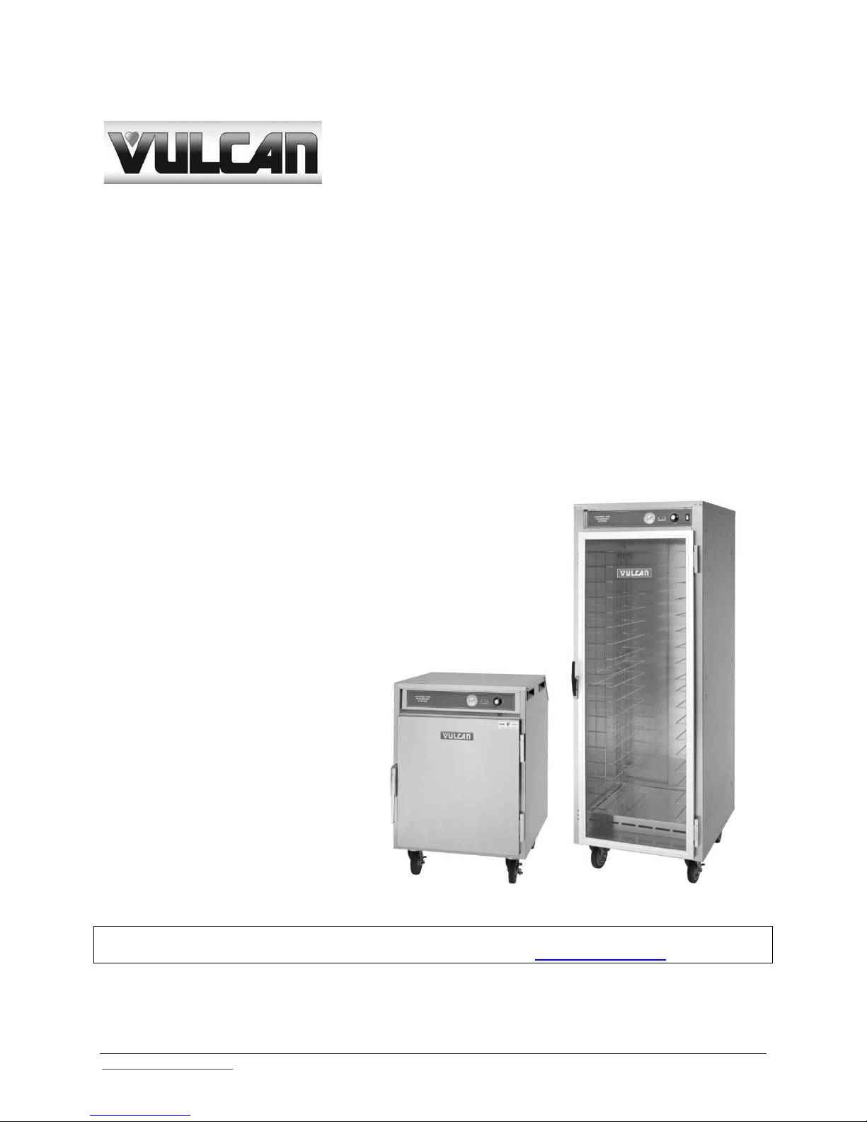
V SERIES FOOD HOLDING &
TRANSPORTATION CABI NETS
AND BANQUET CARTS
MODELS:
VB90 ML-126548
VB96 ML-126550
VB150 ML-126552
VBP5I ML-138030
VBP7I ML-126358
VBP13I ML-126359
VBP15I ML-126360
VBP33 ML-138075
VBP77I ML-126361
VBS15 ML-138033
VHA9 ML-138072
VHA18 ML-138073
VHDP5 ML-138035
VHFA9 ML-138070
VHFA18 ML-138071
VHP3 ML-126343
VHP7 ML-126344
VHP8 ML-126345
VHP15 ML-126346
VHP20 ML-126347
For additional information on Vulcan-Hart or to locate an authorized parts
and service provider in your area, visit our website at www.vulcanhart.com
VULCAN-HART 3600 NORTH POINT BLVD.
DIVISION OF ITW FOOD EQUIPMENT GROUP, LLC BALTIMORE, MD 21222
www.vulcanhart.com Vulcan ©2009 All Rights Reserved F-41140 (09-09)
Page 2

V SERIES FOOD HOLDING, TRANSPORT, & BANQUET CARTS F-41140 (09-09)
IMPORTANT FOR YOUR SAFETY
THIS MANUAL HAS BEEN PREPARED FOR PERSONNEL QUALIFIED TO INSTALL
ELECTRICAL EQUIPMENT, WHO SHOULD PERFORM THE INITIAL FIELD ST ARTUP AND ADJUSTMENTS OF THE EQUIPMENT COVERED BY THIS MANUAL.
FOR YOUR SAFETY
DO NOT STORE OR USE GASOLINE OR OTHER
FLAMMABLE VAPORS OR LIQUIDS IN THE
VICINITYOF THIS OR ANY OTHER APPLIANCE.
WARNING
IMPROPER INSTALLATION, ADJUSTMENT,
ALTERATION, SERVICE, OR M AINTENANCE CAN
CAUSE PROPERTY DAMAGE, INJURY, OR DEATH.
READ THE INSTALLATION, OPE RATING AND
MAINTENANCE INSTRUCTIONS THORO UG HLY
BEFORE INSTALLING OR SERVICING EQUIPMENT.
IN THE EVENT OF A POWER FAILURE,
DO NOT ATTEMPT TO OPERATE THIS DEVICE
1
Page 3

V SERIES FOOD HOLDING, TRANSPORT, & BANQUET CARTS F-41140 (09-09)
TABLE OF CONTENTS
IMPORTANT FOR YOUR SAFETY . . . . . . . . . . . . . . . . . . . . . . . . . . . . . . . . . . . . . . . . 1
GENERAL . . . . . . . . . . . . . . . . . . . . . . . . . . . . . . . . . . . . . . . . . . . . . . . . . . . . . . . . . . . 3
INTRODUCTION . . . . . . . . . . . . . . . . . . . . . . . . . . . . . . . . . . . . . . . . . . . . . . . . . 3
INSTALLATION . . . . . . . . . . . . . . . . . . . . . . . . . . . . . . . . . . . . . . . . . . . . . . . . . . 3
ELECTRICAL REQUIREMENTS . . . . . . . . . . . . . . . . . . . . . . . . . . . . . . . . . . . . . 4
OPERATION . . . . . . . . . . . . . . . . . . . . . . . . . . . . . . . . . . . . . . . . . . . . . . . . . . . . . . . . . 5
CONTROLS . . . . . . . . . . . . . . . . . . . . . . . . . . . . . . . . . . . . . . . . . . . . . . . . . . . . . 5
OPERATING INSTRUCTIONS. . . . . . . . . . . . . . . . . . . . . . . . . . . . . . . . . . . . . . . 6
CLEANING . . . . . . . . . . . . . . . . . . . . . . . . . . . . . . . . . . . . . . . . . . . . . . . . . . . . . . 7
STAINLESS STEEL CARE . . . . . . . . . . . . . . . . . . . . . . . . . . . . . . . . . . . . . . . . . 7
MAINTENANCE . . . . . . . . . . . . . . . . . . . . . . . . . . . . . . . . . . . . . . . . . . . . . . . . . . 8
LOCKOUT / TAGOUT PROCEDURE . . . . . . . . . . . . . . . . . . . . . . . . . . . . . . . . . . . . . . 8
TROUBLESHOOTING . . . . . . . . . . . . . . . . . . . . . . . . . . . . . . . . . . . . . . . . . . . . . . . . . . 9
SERVICE & PARTS INFORMATION . . . . . . . . . . . . . . . . . . . . . . . . . . . . . . . . . . . . . . . 9
SPECIFICATIONS. . . . . . . . . . . . . . . . . . . . . . . . . . . . . . . . . . . . . . . . . . . . . . . . . . . . . 10
WIRING DIAGRAMS . . . . . . . . . . . . . . . . . . . . . . . . . . . . . . . . . . . . . . . . . . . . . . . 11 - 14
2
Page 4

V SERIES FOOD HOLDING, TRANSPORT, & BANQUET CARTS F-41140 (09-09)
GENERAL
INTRODUCTION
Vulcan-Hart Holding & Transport
Cabinets and Banquet Carts are
produced with quality workmanship and
material. Proper installation, usage, and
maintenance of your cabinet will result
in many years of satisfactory
performance.
It is suggested that you thoroughly read
this entire manual and carefully follow all
of the instructions provided.
The V Series Holding & Transport
Cabinets and Banquet Carts provide an
efficient means of transporting and
holding bulk prepared foods at proper
serving temperatures.
INSTALLATION
Before installing, verify that the electrical
service agrees with the specifications on
the rating plate located on the lower
back corner of the cabinet. If the supply
and equipment requirements do not
agree, do not proceed with unpacking
and installation. Contact your VulcanHart Customer Service Department
immediately.
UNPACKING:
The Cabinet was inspected before
leaving the factory. The transportation
company assumes full responsibility for
safe delivery upon acceptance of the
shipment. Immediately after unpacking,
check for possible shipping damage to
the cabinet.
If the cabinet is found to be damaged,
save the packaging material and
contact the carrier within 15 days of
delivery.
Carefully unpack and place in a work
accessible area as near the installation
position as possible.
1. Open the door and carefully
remove any packaging materials
and the retaining straps that hold
the wire plate racks (Banquet
Carts) or the tray slides and tray
slide upright side supports
(Holding & Transport Cabinets).
2. Peel off vinyl protection film.
3. On Banquet Carts, lift the plate
racks into position on the side
brackets.
4. On Holding & Transport
Cabinets, remove cardboard
element cover protector from
cabinet bottom.
Remove adjustable tray slides
from box.
Remove the tray slide supports
and install them in the cabinet.
a. Hook the openings in the
flat flange of the support
over two vertical carriage
bolts on the interior of the
cabinet.
b. Make sure all flang es on
the four supports face the
door opening.
Install tray slides in the cabinet.
Make sure the hook on the end of
the tray slide is up.
3
Page 5
V SERIES FOOD HOLDING, TRANSPORT, & BANQUET CARTS F-41140 (09-09)
CLEANING:
The cabinet should be thoroughly
cleaned prior to putting into service.
Use a mild soap and water solution to
clean the interior of the unit. Never use
harsh chemicals or abrasive pads to
clean the unit.
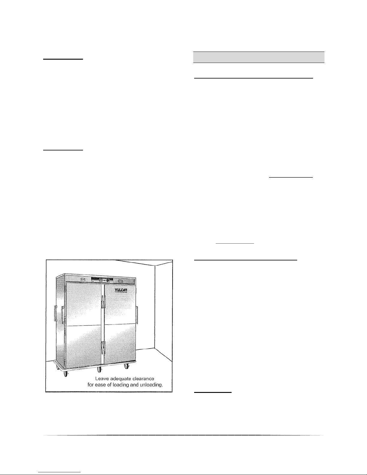
LOCATION:
For efficient cabinet operation, choose a
location that will provide easy loading
and unloading without interfering with
the final assembly of food orders.
The installation location must allow
adequate clearances for servicing and
proper operation. (Fig. 1)
Fig. 1
ELECTRICAL REQUIREMENTS
ELECTRICAL CODES & STANDARDS:
The cabinet must be installed in
accordance with:
In the United States of America:
1. State and Local Codes.
2. National Electrical Code, ANSI/
NFPA-70 (latest edition.) Copies
may be obtained from: The
National Fire Protection
Association, 1Batterymarch Park,
Quincy, MA 02269.
1-617-770-3000 www.nfpa.org
In Canada:
1. Local Codes.
2. Canadian Electrical Code, CSA
C22.1 (latest edition.) Copies
may be obtained from: The
Canadian Standard As soci at ion.
www.csa.ca
ELECTRICAL CONNECTIONS:
The cabinet is factory wired for either
110/120 volt or 208/240 volt, single
phase operation. All 110/120 volt
cabinets are equipped with a 8 foot cord
and NEMA 5-15 plug as standard
equipment. All 208/240 volt cabinets
are equipped with a 8 foot cord and
NEMA 6-15 plug. Refer to wiring
diagrams in the back of this manual .
The cord and plug supplied is a suitable
durable cord with a molded three-prong
plug, and is provided with a proper
strain relief.
WARNING: All cabinets are equipped
with a three-prong plug. It is
imperative that this plug must be
connected into a properly grounded
three-prong receptacle. If the
4
Page 6

V SERIES FOOD HOLDING, TRANSPORT, & BANQUET CARTS F-41140 (09-09)
receptacle is not the proper
grounding type, contact an
electrician. DO NOT REMOVE THE
GROUNDING PRONG FROM THIS
PLUG.
CAUTION: Verify that the power
source matches the Serial Data Plate
located on the lower back corner of
the cabinet and the plug
configuration before the connection
(Fig. 2)
is made. (Fig.2)
PLEASE NOTE:
It is recommended that prior to placing the cabinet in operation that it be
preheated at the highest temperature setting for a period of 30 to 45 minutes.
OPERATION
CONTROLS
Models: VB90, VB96, VB150, VBP5I,
VBP7I, VBP13I, VBP15I, VBP33,
VBP77I, VBS15, VHDP5, VHP3, VHP7,
VHP8, VHP15, VHP20
POWER FULL-RANGE
INDICATOR LIGHT THERMOSTAT
THERMOMETER HEAT INDICATOR LIGHT
(Fig. 3)
Power Indicator Light:
The Red Power Indicator Light indicates
power is supplied to the cabinet. The
red light will stay lit as long as the
cabinet is plugged in.
Heat Indicator Light:
The Amber Heat Indicator Light
indicates the heating element(s) are
heating. The amber light will stay lit as
long as the heating element(s) are
engaged. Once the predetermined
temperature is achieved, the heating
element(s) will begin to cycle. During
this period, the amber light will turn on
and off.
Thermometer:
The Thermometer indicates the interior
temperature of the cabinet.
Thermostat:
The Thermostat turns power on to the
heating element(s). The thermostat
setting is from 1 to 10. The greater the
thermostat setting number, the higher
the temperature. (Fig. 4)
5
Page 7

V SERIES FOOD HOLDING, TRANSPORT, & BANQUET CARTS F-41140 (09-09)
Setting
Thermostat
Approximate
Temperature
1 100⁰F (37⁰C)
2 110⁰F (43⁰C)
3 120⁰F (49⁰C)
4 130⁰F (54⁰C)
5 140⁰F (60⁰C)
6 150⁰F (66⁰C)
7 160⁰F (71⁰C)
8 170⁰F (77⁰C)
9 180⁰F (82⁰C)
10 190⁰F (88⁰C)
(Fig. 4)
Models: VHFA9, VHFA18
POWER FULL-RANGE ON / OFF
INDICATOR LIGHT THERMOSTAT SWITCH
THERMOMETER HEAT INDICATOR LIGHT
(Fig. 5)
Power Indicator Light:
The Red Power Indicator Light indicates
the cabinet is plugged in and the ON /
OFF Switch is in the ON position. The
red light will stay lit until the ON / OFF
switch is in the OFF position.
Heat Indicator Light:
The Amber Heat Indicator Light
indicates the heating element(s) are
heating. The amber light will stay lit as
long as the heating element(s) are
engaged. Once the predetermined
temperature is achieved, the heating
element(s) will begin to cycle. During
this period, the amber light will turn on
and off.
ON / OFF Switch:
The ON / OFF Switch supplies electrical
power to the cabinet and turns on the
fan. The cabinet will not have power
unless the switch is in the ON position.
Thermometer:
The Thermometer indicates the interior
temperature of the cabinet.
Thermostat:
The Thermostat turns power on to the
heating element(s). The thermostat
setting is from 1 to 10. The greater the
thermostat setting number, the higher
the temperature. (Fig. 4)
OPERATING INSTRUCTIONS
Once the cabinet has been connected to
the appropriate power source, the
cabinet is ready for operation. Begin by
turning the thermostat dial to the
number 5. This will cause the heating
element(s) to start heating. Once the
red light is lit, the thermostat dial can be
turned to the desired setting.
When cooking is completed, turn the
thermostat dial to the OFF position.
Models VHFA9 and VHFA18 turn the
thermostat dial to the OFF position and
switch the ON / OFF switch to the OFF
position.
NOTE:
The temperature in any heated
cabinet will fluctuate as the heating
element(s) cycles on and off. The
thermostat setting will provide an
average temperature in the cabinet.
However, the operator should always
monitor the food product to insure
that it remains at a proper temperature.
6
Page 8

V SERIES FOOD HOLDING, TRANSPORT, & BANQUET CARTS F-41140 (09-09)
CLEANING
WARNING:
Always UNPLUG ELECTRICAL
POWER SUPPLY before cleaning.
DAILY:
1. Unplug electrical power supply.
2. Allow warmer to cool before
cleaning.
3. Clean the interior of the cabinet
with a mild soap and water.
Never use harsh chemicals or
abrasive pads to clean the cabinet.
4. Rinse and dry with a soft dry
cloth.
5. Clean the exterior of the cabinet
with a clean damp cloth.
HEAVY-DUTY CLEANING:
For heavy-duty cleaning, use warm
water, a degreaser, and a plastic,
stainless steel, or Scotch-Brite pad.
Never rub in a circular motion -- rub
gently in the direction of the steel grain.
Always rinse thoroughly.
STAINLESS STEEL CARE
CLEANING:
Stainless Steel contains 70 – 80% iron,
which will rust if not properly maintained.
Stainless Steel also contains 12 – 30%
chromium, which forms an invisible
passive, protective film that shields
against corrosion.
If the protective film remains intact, the
stainless steel will remain intact.
However, if the film is damaged, the
stainless steel can break down and rust.
PREVENTIVE CARE:
To prevent stainless steel breakdown, follow these steps:
1. Never use any metal tools,
scrapers, files, wire brushes,
or scouring pads (except for
stainless steel scouring pads,)
which will mar the surface.
2. Never use steel wool – which
will leave behind particles that will
rust.
3. Never use acid-based or
chloride containing cleaning
solutions – which will break
down the protective film.
4. Never rub in a circular motion.
Always rub gently in the direction
of the steel grain.
5. Never leave any food products
or salt on the surface. Many
foods are acidic. Salt contains
chloride.
PRESERVING & RESTORING:
Special stainless steel polishing
cleaners can preserve and restore the
protective film.
Preserve the life of stainless steel with a
regular application of a high-quality
stainless steel polishing cleaner, as a
final step to daily cleaning.
If signs of breakdown appear, restore
the stainless steel surface. First,
thoroughly clean, rinse, and dry the
7
Page 9

V SERIES FOOD HOLDING, TRANSPORT, & BANQUET CARTS F-41140 (09-09)
surface. Then, on a daily basis, apply a
high-quality stainless steel polish
according to manufacturer’s instructions.
HEAT TINT:
Darkened areas, called “heat tint,” may
appear on stainless steel exposed to
excessive heat. Excessive heat causes
the protective film to thicken. This is
unsightly, but is not a sign of permanent
damage.
To remove heat tint, follow the routine
cleaning procedure. Stubborn heat tint
will require heavy-duty cleaning.
To reduce heat tint, limit the exposure of
equipment to excessive heat.
MAINTENANCE
WARNING;
The Cabinet and its parts are HOT.
Be very careful when Operating,
Cleaning, or Servicing the cabinet.
ALWAYS: UNPLUG ELECTRICAL
POWER SUPPLY BEFORE
SERVICING THE CABINET.
LOCKOUT / TAGOUT PROCEDURE
WARNING
PROCEDURE before removing any sheet metal panels or
attempting to service this equipment.
FAILURE TO COMPLY WITH THIS PROCEDURE CAN CAUSE
PROPERTY DAMAGE, INJURY OR DEATH.
The Lockout / Tagout Procedure is used to protect personnel working
on an electrical appliance. Before performing any type of maintenance or service on an
electrically operated appliance, follow these steps:
1. In electrical box, place unit’s circuit breaker into OFF position.
2. Place a lock or other device on electrical box cover to prevent someone from
placing circuit breaker ON.
3. Place a tag on electrical box cover to indicate that unit has been disconnected for
service and power should not be restored until tag is removed by maintenance
personnel.
4. Di sco nnect uni t power cord from electrical outlet.
5. Place a tag on cord to indicate that unit has been disconnected for service and
power should not be restored until tag is removed by maintenance personnel.
Always perform the LOCKOUT / TAGOUT
8
Page 10

V SERIES FOOD HOLDING, TRANSPORT, & BANQUET CARTS F-41140 (09-09)
SYMPTOMS POSSIBLE CAUSES REMEDY
Cabinet not c onnect ed to
power sourc e.
Connect cabinet t o power s ource.
ON/ O F F swi tc h no t ON (VHFA
series)
Turn ON/OFF s wi t ch ON
Check ci rc ui t break er
Chec k G F CI
Moist ure problem . Dry moi st ure probl em .
Short ed el em ent Contac t A ut hori zed S ervice Provider.
Pinched/ dam aged wi re. Contac t A ut hori zed S ervice Provider.
Damaged power cord. Contac t A ut hori zed S ervice Provider.
Cabinet i s c onnect ed to
power sourc e, s witc h i s ON,
ci rcuit breaker is ON, but
cabi net i s not heating.
Defecti ve: element,
therm om et er, t hermost at, et c.
Contac t A ut hori zed S ervice Provider.
Power/ Heat Indicat or Light
not l i t .
Light fault y Contac t A ut hori zed S ervice Provider.
Door not s hut properly or
needs adj ust m ent
Check door seal and Contac t
Aut hori zed S ervice Provider.
Defecti ve: element,
therm om et er, t hermost at,
therm os tat requi res
adjustment
Contac t A ut hori zed S ervice Provider.
ON/ O F F swi tc h no t ON (VHFA
series)
Turn ON/OFF s wi t ch ON
Defecti ve fan. Contact Aut horized S ervice P rovider.
Cabinet not operat i ng
No power.
GFCI or Ground Fault
Circui t Indic ator tri pped
Cabinet does not heat
properly
Fan not operating (V HF A
series)
TROUBLESHOOTING
SERVICE & PARTS INFORMATION
To obtain Service and Parts information concerning this model, contact Vulcan-Hart
Service Department at the address listed on the front cover of this manual or refer to
our website: www.vulcanhart.com for a complete listing of Authorized Service and Parts
depots.
Customer Service 1-800-814-2028
Technical Service 1-800-814-2028
Service Parts 1-800-814-2028
When calling for service, have the model number and serial number available.
9
Page 11

V SERIES FOOD HOLDING, TRANSPORT, & BANQUET CARTS F-41140 (09-09)
SPECIFICATIONS
MODEL NO.
IN (mm)
IN (mm)
(mm)
SHIPPING
WT.
Lb. (kg)
VOLTS
WATTS
AMPS
VB90
(1822)
42.75"
(1086)
31.75"
(806)
242#
(110 kg)
120
2000
16.6
VB96
(1575)
29"
(737)
(1308)
435#
(197 kg)
120
2000
16.6
VB150
(1854)
29"
(737)
61.25"
(1556)
590#
(268 kg)
120
2000
16.6
VBP5I
(800)
33.75"
(857)
28.25"
(718)
170#
(77 kg)
120
1200
10
VBP7I
(959)
33.75"
(857)
28.25"
(718)
230#
(104 kg)
120
1200
10
VBP13I
(1454)
33.75"
(857)
28.25"
(718)
340#
(154 kg)
120
1200
10
VBP15I
(1702)
33.75"
(857)
28.25"
(718)
(163 kg)
120
1200
10
VBP33
43.5"
(1105)
(782)
(643)
120
1200
10
VBP77I
(1842)
31.75"
(806)
(622)
400#
(182 kg)
120
2400
20
VBS7
37.625"
(956)
30.25"
(781)
23.75"
(584)
195#
(90 kg)
120
1200
10
VBS15
(1676)
30.25"
(781)
23.75"
(584)
315#
(144 kg)
120
1200
10
VHA9
43.5"
30.75"
VHA18
(1804)
(782)
(643)
NA
NA
NA
VHDP5
(1582)
(966)
24.75"
(629)
370#
(169 kg)
120
2000
16.7
VHFA9
(1105)
30.75"
(782)
(643)
190#
(87 kg)
120
1200
10
VHFA18
(1804)
(782)
(643)
225#
(102 kg)
120
2000
16.7
VHP3
(597)
23.75"
(604)
(457)
80#
(36.6 kg)
120
600
5
VHP7
(724)
25"
(635)
18.25"
(464)
80#
(36.3 kg)
120
600
5
VHP8
(800)
25"
(635)
18.25"
(464)
(40.9 kg)
120
600
5
VHP15
(1556)
26.75"
(680)
21.25"
540)
196#
(89 kg)
120
1200
10
VHP20
(1549)
29"
(737)
(1003)
264#
(120 kg)
120
1200
10
WIDTH
HEIGHT
71.75"
DEPTH
IN
62"
73"
31.5"
37.75"
57.25"
67"
72.5"
66"
(1105)
71"
30.75"
(782)
30.75"
51.5"
360#
25.25"
24.5"
25.25"
(643) NA NA NA
25.25"
62.25"
43.5"
71"
23.5"
28.5"
31.5"
61.25"
61"
38"
30.75"
25.25"
25.25"
18"
90#
39.5"
10
Page 12

V SERIES FOOD HOLDING, TRANSPORT, & BANQUET CARTS F-41140 (09-09)
WIRING DIAGRAMS
11
Page 13

V SERIES FOOD HOLDING, TRANSPORT, & BANQUET CARTS F-41140 (09-09)
12
Page 14

V SERIES FOOD HOLDING, TRANSPORT, & BANQUET CARTS F-41140 (09-09)
13
Page 15

V SERIES FOOD HOLDING, TRANSPORT, & BANQUET CARTS F-41140 (09-09)
14
 Loading...