

Vulcan-Hart VBP5, V Series, VBP7, VBP13, VBP15 Service Manual
...
SERVICE MANUAL
V Series Heated Holding
Insulated Cabinets
VBP5 ML-138030
VBP7 ML-126358
VBP13 ML-126359
VBP15 ML-126360
VBP18
VHP7 ML-126344
VHP15 ML-126346
VPT7
VPT13
VPT15
VPT18
- NOTICE -
This Manual is prepared for the use of trained Vulcan Service
Technicians and should not be used by those not properly
qualified.
This manual is not intended to be all encompassing. If you have
not attended a Vulcan Service School for this product, you should
read, in its entirety, the repair procedure you wish to perform to
determine if you have the necessary tools, instruments and skills
required to perform the procedure. Procedures for which you do
not have the necessary tools, instruments and skills should be
performed by a trained Vulcan Service Technician.
The reproduction, transfer, sale or other use of this Manual,
without the express written consent of Vulcan, is prohibited.
This manual has been provided to you by ITW Food Equipment
Group LLC ("ITW FEG") without charge and remains the property
of ITW FEG, and by accepting this manual you agree that you will
return it to ITW FEG promptly upon its request for such return at
any time in the future.
A product of Vulcan-Hart 3600 North Point Blvd Baltimore, MD 21222
F45748 (0219)

V Series Heated Holding Insulated Cabinets
TABLE OF CONTENTS
SERVICE UPDATES ....................................................................................... 3
SERVICE UPDATES ................................................................................... 3
TIS DOCUMENT LIST - V SERIES HEATED HOLDING INSULATED CABINETS ......................... 3
GENERAL .................................................................................................. 4
INTRODUCTION ....................................................................................... 4
INSTALLATION, OPERATION AND CLEANING ......................................................... 4
TOOLS ................................................................................................. 4
SPECIFICATIONS ...................................................................................... 4
DATA PLATE LOCATIONS ............................................................................. 4
REMOVAL AND REPLACEMENT OF PARTS ............................................................... 5
TOP COVER ........................................................................................... 5
FOOD COMPARTMENT FAN ........................................................................... 5
HEATING ELEMENTS .................................................................................. 6
POWER CORD ......................................................................................... 7
HIGH LIMIT SWITCH ................................................................................... 8
TERMINAL BLOCK ..................................................................................... 8
TEMPERATURE PROBE ............................................................................... 8
COMPONENT COOLING FAN .......................................................................... 9
CONTROL BOARD ..................................................................................... 9
DOOR GASKET ....................................................................................... 11
DOOR ASSEMBLY .................................................................................... 11
DOOR LATCH (MAGNETIC) ........................................................................... 12
SERVICE PROCEDURES AND ADJUSTMENTS ........................................................... 14
TEMPERATURE VERIFICATION ...................................................................... 14
HEATER ELEMENT TEST ............................................................................. 14
ELECTRICAL OPERATION ................................................................................ 15
COMPONENT DESCRIPTIONS ....................................................................... 15
WIRING DIAGRAM .................................................................................... 16
SEQUENCE OF OPERATION ......................................................................... 16
TROUBLESHOOTING ................................................................................. 17
© VULCAN 2019
F45748 (0219) Page 2 of 17
V Series Heated Holding Insulated Cabinets - SERVICE UPDATES
SERVICE UPDATES
SERVICE UPDATES
JANUARY 2019
• New service manual release.
TIS DOCUMENT LIST - V SERIES HEATED HOLDING INSULATED CABINETS
SERVICE TAB
Document Title Document Type
V Series Heated Holding Transportation Cabinets Service Manual
SERVICE MULTIMEDIA TAB
Document Title Document Type
V Series Heated Holding Transportation Cabinets Installation &
Operation
V Series Heated Holding Transportation Cabinets Specifications Specification
Operators Manual
PARTS TAB
Document Title Document Type
V Series Heated Holding Transportation Cabinets Parts Catalog
Page 3 of 17 F45748 (0219)
V Series Heated Holding Insulated Cabinets - GENERAL
GENERAL
INTRODUCTION
This manual is applicable only to models listed on the
cover page. Procedures in this manual will apply to all
models unless specified. Pictures and illustrations can
be of any model unless they need to be model specific.
INSTALLATION, OPERATION AND
CLEANING
For detailed installation, operation and cleaning
instructions, refer to the Installation & Operation
Manual sent with each unit. The manual is also
available online at www.vulcanequipment.com.
TOOLS
Standard
• Standard set of hand tools.
• VOM with minimum of NFPA-70E CATIII 600V,
UL/CSA/TUV listed. Sensitivity of at least 20,000
ohms per volt and the ability to measure DC
micro amps. Meter leads must also be rated at
CAT III 600V.
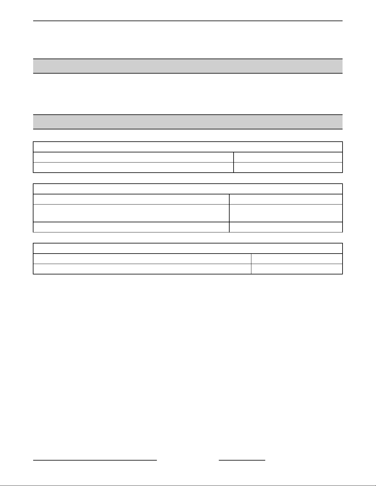
DATA PLATE LOCATIONS
DATA PLATE LOCATED ON BACK PANEL
• Clamp on type amp meter with minimum of
NFPA-70E CAT III 600V,UL/CSA/TUV listed.
• Temperature tester (thermocouple type).
• ESD (Electrostatic discharge) Protection Kit.
Special
• Handheld, digital temperature and humidity
sensor Grainger No. 3LYH7 or equivalent.
SPECIFICATIONS
MODELS VOLTS WATTS AMPS
VBP and
VPT
120V 1,500 12.5
240V 1,500 6.25
INSIDE DATA PLATE
F45748 (0219) Page 4 of 17
V Series Heated Holding Insulated Cabinets - REMOVAL AND REPLACEMENT OF PARTS
REMOVAL AND REPLACEMENT OF PARTS
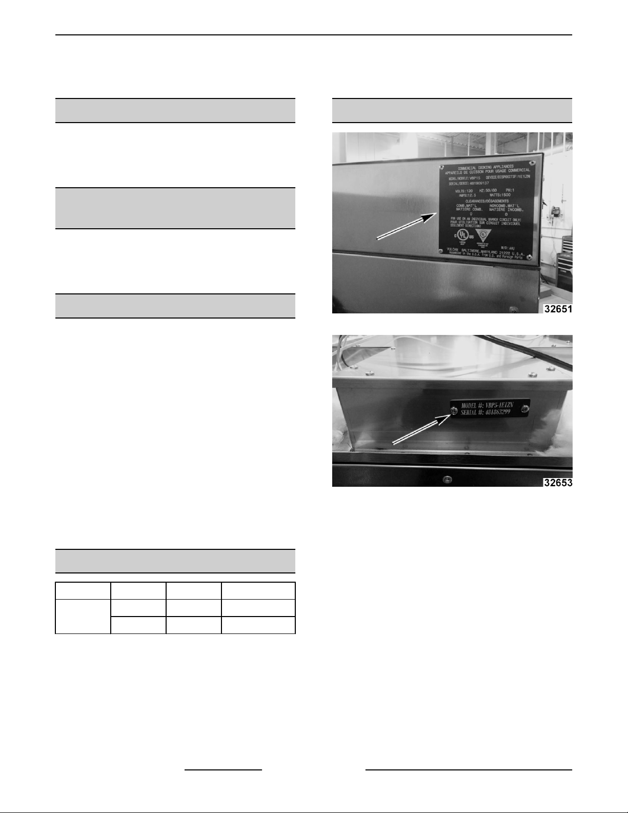
TOP COVER
Disconnect the electrical power to
the machine and follow lockout /
tagout procedures.
NOTE: Remove top cover to access power cord,
cooling fan, and control board.
1. Remove screws from top and side of top cover.
2. Remove insulation (1, Fig. 5).
Fig. 5
3. Note and disconnect wiring from terminal block
and control board.
4. Remove inside access cover (1, Fig. 6).
Fig. 3
Fig. 4
2. Lift cover off cabinet.
3. Reverse procedure to install.
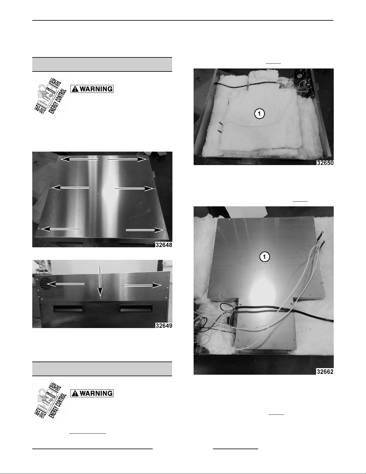
FOOD COMPARTMENT FAN
Disconnect the electrical power to
the machine and follow lockout /
tagout procedures.
Fig. 6
5. Remove fan mounting bracket.
6. Remove screws from fan.
7. Install fan with label (1, Fig. 7) up.
1. Remove TOP COVER .
Page 5 of 17 F45748 (0219)
V Series Heated Holding Insulated Cabinets - REMOVAL AND REPLACEMENT OF PARTS
Fig. 7
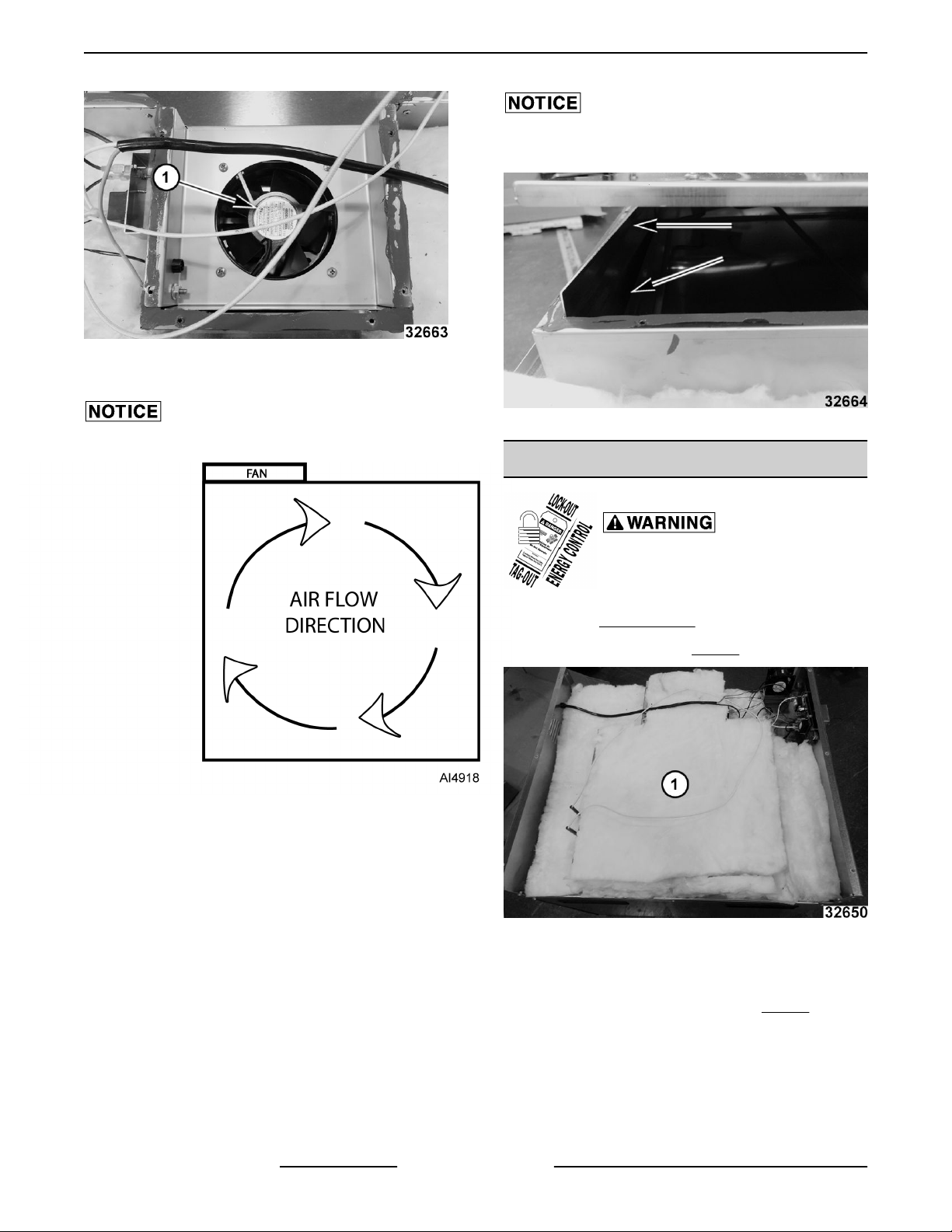
8. Reverse procedure to install.
Verify air flow direction in cavity.
When installing inside access cover, verify edge
inserts into slot without catching.
Fig. 9
HEATING ELEMENTS
Fig. 8
Disconnect the electrical power to
the machine and follow lockout /
tagout procedures.
1. Remove TOP COVER .
2. Remove insulation (1, Fig. 10).
Fig. 10
3. Note and disconnect wires from terminal block
and control board.
4. Remove inside access cover (1, Fig. 11).
F45748 (0219) Page 6 of 17
 Loading...