

Page 1
SERVICE MANUAL
VL BOILER BASE SERIES
CONVECTION STEAMERS
(GAS, ELECTRIC, DIRE CT AND REGENERATED)
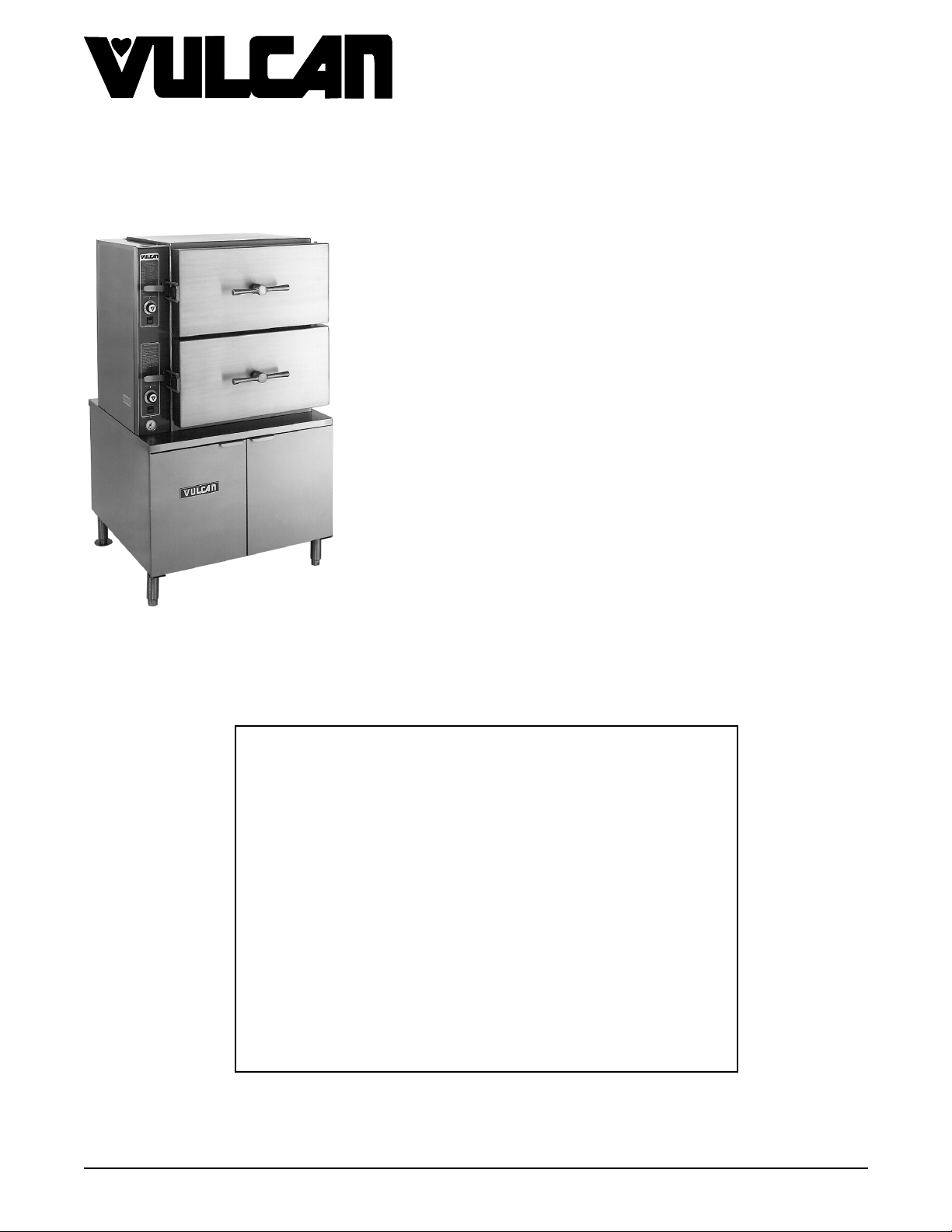
VL2GPS ML-52391 VL2DPS ML-52749
VL2GMS ML-52388 VL2DMS ML-52750
VL2GAS ML-52390 VL2DAS ML-52751
VL2GSS ML-52389 VL2DSS ML-52752
VL3GPS ML-52395 VL3DPS ML-52753
VL3GMS ML-52392 VL3DMS ML-52754
VL3GAS ML-52394 VL3DAS ML-52755
VL3GSS ML-52393 VL3DSS ML-52756
VL2EPS ML-52741 VL2RPS ML-52757
VL2GPS SHOWN
This Manual is prepared for th e use of trained Vulcan Service
Technicians and should not be used by those not properly
qu alifi ed. If yo u have attend ed a Vulcan Service School for this
product, you may be qualified to perform all the procedures
described in this man ual.
This manual is not intended to be all encompassing. If you have
not attended a Vulcan Service School for this produc t, y ou should
read, in its entirety, th e repair procedure you wish to perform to
determine if you have the necessary tools, instruments a nd s k ills
required to perfo rm t he procedure. Procedures for which you do
not have th e n ecessary tools, instruments and skills should be
performed b y a t rained Vul can Service Technician.
VL2EMS ML-52742 VL2RMS ML-52758
VL2EAS ML-52743 VL2RAS ML-52759
VL2ESS ML-52744 VL2RSS ML-52760
VL3EPS ML-52745 VL3RPS ML-52761
VL3EMS ML-52746 VL3RMS ML-52762
VL3EAS ML-52747 VL3RAS ML-52763
VL3ESS ML-52748 VL3RSS ML-52764
- NOTICE -
Reproduction or other use of this Manual, without the express
written consent of Vulcan, is prohibited.
A product of VULCAN-HART LOUISVILLE , KY 40201-0696
Form 24650 (M ay 1999)
Page 2

VL SERIES STEAMERS
g
g
g
g
g
g
g
g
g
g
g
g
g
g
g
g
TABLE OF CONTENTS
GENERAL............................................................................. 4
Introduction ........................................................................ 4
Compartment Pan Capacity ........................................................ 4
Model Desi
Water Conditi onin
Tools ............................................................................. 5
Specifications ...................................................................... 5
Water Supply ................................................................... 5
Steam Supply ................................................................... 5
Gas Steamers .................................................................. 6
Electric Steamers................................................................ 6
Steamer Operation .................................................................. 7
Gas Powered Steam Boiler ........................................................ 7
Electrically Powered Steam Boiler ................................................... 7
Re
enerated Steam Powered Boiler .................................................. 7
Direct Steam Powered Cooker ...................................................... 8
Boiler B lowdown and Steamer Shut off ................................................ 8
Cookin
Component Func tion ................................................................ 11
Cabinet Base Boiler Controls ...................................................... 11
Cookin
nations .............................................................. 4
.................................................................. 4
Compartment Control s ..................................................... 8
Compartment Control s .................................................... 13
REMOVAL AND REPLACEMENT OF PARTS ................................................ 14
Component Locat ions ............................................................... 14
Water Level Controls - Low Level Cut off and Differ ential .................................... 17
Water Level Gau
Cyclin
Boiler Assembly.................................................................... 18
Hi
Boiler Fill and Cold W ater Condenser Solenoid Valves ...................................... 19
Pilot and Thermocoupl e A ssembly (Gas Models) ........................................... 19
Gas Combinat ion Control Valve ........................................................ 19
Compartm ent Gasket and Door Screw Nut, Door and Bushin
Heater Contactor s .................................................................. 21
Heatin
Re
SERVICE PROCEDURES AND ADJUSTMENTS .............................................. 22
Boiler............................................................................ 22
Water Level Control(s) T est ........................................................... 24
Cyclin
Fill and Cold Wat er S olenoid Valves .................................................... 26
Compartment Pressure Adjustment ..................................................... 26
Hi
Boiler Not Fillin
Boiler B lowdown Drain Solenoid Valve .................................................. 27
Boiler Slow to Pressurize............................................................. 28
Inlet Water Strainer ................................................................. 29
Pilot and Thermocoupl e A ssembly (Gas Models) ........................................... 29
Gas Burners....................................................................... 31
Automatic I
Gas Manifold Pressure Adjustment ..................................................... 33
and High Limit Pressure Switches
(Gas and Electr ic Models) ........................................................ 17
h Limit Thermostat ............................................................... 18
Elements .................................................................. 21
enerated Steam Models (Steam Coil) ................................................ 21
Inspection..................................................................... 22
Clean-out (All Boiler Models) ...................................................... 22
Delimin
Descaler...................................................................... 23
and High Limit Pressure Switches
(Gas and Electr ic Models) ........................................................ 25
h Limit Thermostat ............................................................... 27
Air Shutter Adjustment ........................................................... 31
Inspection..................................................................... 31
e Assembly ......................................................... 17
s ............................... 20
Only (Models with Deliming Port Assembly).................................... 23
with Water ........................................................... 27
nition S y stems (Gas Models) ................................................ 31
Page 2 of 88
Page 3

VL SERIES STEAMERS
g
g
g
g
g
g
g
g
g
g
g
g
g
g
g
g
g
Direct Steam Models ................................................................ 34
enerated Steam (Older Models) ..................................................... 34
Re
Heater Contactor s .................................................................. 34
Heatin
Elements .................................................................. 34
Thermal Switch - Prevent and Aut omatic M odels ........................................... 36
Water Level Gau
e Assembly ......................................................... 36
Steam Gate Valve(s) ................................................................ 37
ELECTRICAL OPERATION .............................................................. 38
Water Level Controls ................................................................ 38
Solid State - Low Level Cut-off & Differential Contr ol .................................... 38
Electro M ec hanical - Low Level Cut-off & Differential Control .............................. 40
Sequence of O per ation .............................................................. 42
Gas Models ................................................................... 42
Electric Models ................................................................. 45
Schematics, Gas Steam er s, B oiler Controls
VL2G AND VL3G - P r event, A utomati c , Standard and Manual ............................. 49
Manual I
Electronic I
Manual I
Electronic I
Wi ri n
Diagrams, Gas Steamers, Boiler Controls
nition, Standard Controls .............................................. 49
nition, Standard Controls ............................................ 50
nition, Csd-1 Code Controls ............................................ 51
nition, Csd-1 Code Controls .......................................... 52
VL2G AND VL3G - P r event, A utomati c , Standard and Manual ............................. 54
Manual I
Electronic I
Manual I
Electronic I
nition, Standard Controls .............................................. 54
nition, Standard Controls ............................................ 56
nition, Csd-1 Code Controls ............................................ 58
nition, Csd-1 Code Controls .......................................... 60
Schematics, Elect r ic Steam er s, B oiler Controls
VL2E AND VL3E - Prevent, A utomati c , Standard and Manual ............................. 62
Auto Blowdown, Standard Cont r ols .............................................. 62
Auto Blowdown, Cal-code Controls .............................................. 63
Wi ri n
Diagrams, El ec tric Steamers, Boiler Controls
VL2E AND VL3E - Prevent, A utomati c , Standard and Manual ............................. 64
Auto Blowdown, Standard Cont r ols (Contactor - 1 Std.) .............................. 64
Auto Blowdown, Standard Cont r ols (Contactors - 2 Std.) .............................. 66
Manual Blowdown, Cal-c ode Controls (Contactor s - 1 Std. 1 Aux. ) ...................... 68
Auto Blowdown, Cal-code Controls ( Contactor s - 1 Std. 1 Aux. ) ........................ 70
Auto Blowdown, Cal-code Controls (Contactor s - 2 Std. 2 Aux. ) ........................ 72
Manual Blowdown, Cal-c ode Controls (Contactor s - 2 Std. 2 Aux. ) ...................... 74
Wi ri n
Diagrams, El ec tric Heater Circuits
VL2E AND VL3E - Prevent, A utomati c , Standard and Manual ............................. 76
Schematic and Wirin
Diagrams, Dir ec t Steamers, Cabinet Base
VL2D AND VL3D - Prevent, Automati c , Standard and Manual ............................. 77
Wi ri n
Diagrams, Regenerated Steamers, Boiler Controls
VL2R AND VL3R - Prevent, Automati c , Standard and Manual ............................. 78
Schematic and Wirin
Diagrams - Compar tment Contr ols .................................... 80
Prevent ...................................................................... 80
Automatic..................................................................... 81
Standard ..................................................................... 82
Manual ....................................................................... 83
TROUBLESHOOTING .................................................................. 84
© VULCAN 1999
Page 3 of 88
Page 4
VL SERIES STEAMERS - GENERAL
g
g
g
g
g
g
g
g
g
g
g
g
g
g
g
g
g
g
g
g
g
g
g
GENERAL
INTRODUCTION
Steam Cooking
e capacity pr essure steam er s offer an efficient
Lar
way to produce a wide v ar iety of foods in smal l
portions or lar
cook fresh foods, blanch foods for com plete cookin
later or will steam defrost and cook froz en foods.
Cookin
maximum c olor, f lavor and nutriti onal value with the
least expenditure of ener
Compartment P an Capacity
PANS PER
COMPARTMENT
* Remove center support for 18x20 i nc h pans
er batches. Steamers can be used to
with steam assures the food will retain its
y and labor.
SIZE
4 12" x 20" 6.0
6 12" x 20" 4.0
8 12" x 20" 2.5
6 *18" x 20" 1.0
DEPTH
(INCHES)
Boiler Code Descriptions
Vulcan-Hart incorporates redundant controls in
compliance with Californi a Code ( Cal-Code) and
CSD-1 as an option on steam equipment when
required by state and/or local buildin
requirem ents. Descriptions of the codes are li sted
below.
Cal-Code Construction
electrical safet y c ircuits that, if tripped, must
manually be reset aft er the conditi on c ausi n
subsides. These controls consist of one dual
function water level cyclin
control and one sin
off control (A ux - LLCO) and a hi
switch in conjunc tion with a m ec hanical pressure
relief valve.
CSD-1 Constructi on
electrical safet y c ircuits that, if tripped, must
manually be reset aft er the conditi on c ausi n
subsides. These controls consist of one dual
function water level cyclin
control and one sin
off control (LLCO) and a hi
in conjunction with a m ec hanical pressure relief
valve. A dditional ly, both circuits have individual
indicator li
verifi c ation of the shutdown mode.
hts that will illuminate for a visual
- Redundant controls in the
and low level cut off
le function low water level cut-
- Redundant controls in the
and low level cut off
le function low water level cut-
h pressure relief switch
code
the trip
h pressure relief
the trip
Model Designations
L X X XX
V
Cooking Control Ty pes:
PS - Prevent Steam
AS - Automatic Steam
SS - Standard Steam
MS - Manual Steam
Heatin
G - Gas
E - Electric
D - Direct
R - Re
Number of Compartments
Lar
Steamer
Vulcan
System:
enerated
e Capacity Pr essure
Cal-Code and CSD-1 construc tion both requi r e
operator int er vention in the event of a shutdown.
CSD-1 is more informative by usin
to show which safety system was shutdown.
indicator lights
WATER CONDITIONING
Furnishing the boiler with soft water to reduc e scale
formation is important. Scale formation will reduce
steam output, cause premature component f ailure,
and shorten equipment life. Most water supplies
contain scale pr oduc in
and Ma
minerals remain and dissolve i nto the water. As the
concentration of these m inerals increases past a
certain point, they prec ipitate from the water and
coat the insi de of the boiler, heati n
thermostat bulbs and water lev el probes. Because of
the hi
precipitated mi ner als bake onto them and bec ome
very difficult t o rem ove.
nesium. As steam is generated, the
h temperat ur e of these surfaces, the
minerals such as Calcium
element s,
Page 4 of 88
Page 5
VL SERIES STEAMERS - GENERAL
g
g
g
g
g
g
g
g
g
g
g
g
g
g
g
This causes several pr oblems:
1. Reduce the heat transfer effici enc y of the
heatin
syste m.
2. Cause premature failure of Electric heaters.
3. Water level probes will
ive false readings.
4. Thermostat bulbs will sense temperature
incorrectly.
These problems are common to any manufacturer's
steamer re
prevented by furnishin
ardless of design, but they can all be
the boiler with soft water.
Vulcan recommends the water contain less than
60ppm of “ total dissolved solids” (TDS) and hav e a
PH fact or between 7 to 8. These water properties
can be achieved by usin
a properly maintained
water softener.
Other chemical proper ties in water supplies can also
affect
ood steam generation and vary from within
each state and locality.
The water level probes in t he boiler use ions in t he
water to detect the water level. Do not use
fully
demineralized or de-ionized water since i t is "non
conductive" and the water level can not be detected.
NOTE: The use of strainers, or filters will not
remove mi ner als from the water.
Vulcan recommends that a local water treat ment
specialist be consulted before t he installat ion of any
steam
Steamers that operate over a lon
enerating equipment .
period of time
without the benefit of a water softener, whic h have
developed a heavy scale build up, shoul d be
cleaned bef or e usi n
a water softener.
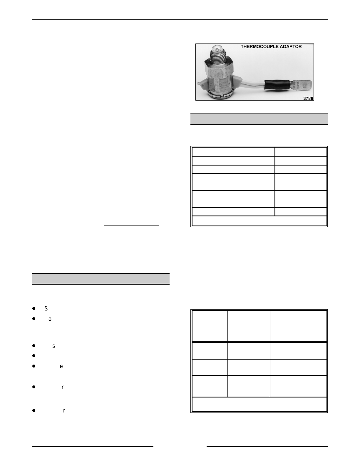
TOOLS
Standard
NOTE: A daptors vary between manufact ur er s. A n
example of one adaptor type is pictur ed below.
SPECIFICATIONS
Water Supply
Supply pressure should be 20-80 psi
In line str ainer for suppl y line (Not Supplied)
Supply connect ion cold
Total dissolved solids (TDS)* less than 60 ppm
Total alkalinity less than 20 ppm
Silica less than 13 ppm
Chloride less than 30 ppm
PH factor 7 to 8
(*17.1 ppm = 1
Steam Supply
Dry steam must be provided to the steam er for
suitable use. If the steam is heavy wit h c ondensate,
a Ball F loat Trap must be used in the li ne and
plumbed in before the pr essure reducin
ensure rapid heat up of heavy c old loads, the steam
supply line must be sized to maintain pr essure as
outlined below.
rain of har dness)
valv e. To
Standard set of hand tools.
Volt-Ohm-Meter (VOM) with AC current tester.
(Any quali ty VOM with a sensitivity of at least
20,000 ohms per volt can be used)
Gas leak checkin
Gas pressure manometer
Temperat ur e meter and thermocouple.
equipment .
Special
CLR Treatm ent Kit - Used to remov e
Calcium/Lime/Rust from a boiler ( Contact
Vulcan Author ized Service Centers ).
Adaptor to test thermocoupl e c losed circuit
es (DC) on gas models with m anual
volta
nition ( pur c hase l oc ally).
i
DIRECT STEAM
STEAMERS
(POTABLE)
Supply
Pressure Input
Flow Rate 50 lb. per hour per
Pressure
Reducing Valve
Output
*Potable stea m is no t required for regene rated models but could
be used.
15 psi (min.) 15 psi (min.)
compartment
10 psi (furnished) set accordingly for good
REGENERATED
STEAMERS OLDER MODELS
(*NON-POTABLE)
125 lb. per hour
steam generation (1012psi)
Page 5 of 88
Page 6
Gas Steamers
VL SERIES STEAMERS - GENERAL
INPUT
(BTU/HR)
MODEL NAT. PROP. NAT. PROP. RECOMMEND MIN RECOMMEND MIN
VL2GPS
VL2GMS
VL2GAS
VL2GSS
VL3GPS
VL3GMS
VL3GAS
VL3GSS
200,000 200,000
240,000 240,000
200,000 200,000
240,000 240,000
200,000 200,000
240,000 240,000
200,000 200,000
240,000 240,000
200,000 200,000
240,000 240,000
200,000 200,000
240,000 240,000
200,000 200,000
240,000 240,000
200,000 200,000
240,000 240,000
MANIFOLD
PRESSURE
(INCHES W.C.)
4.0 10.0 7.0 5.0 11.0 11.0 14.0 360 3.0
4.0 10.0 7.0 5.0 11.0 11.0 14.0 360 3.0
4.0 10.0 7.0 5.0 11.0 11.0 14.0 360 3.0
4.0 10.0 7.0 5.0 11.0 11.0 14.0 360 3.0
4.0 10.0 7.0 5.0 11.0 11.0 14.0 360 3.0
4.0 10.0 7.0 5.0 11.0 11.0 14.0 360 3.0
4.0 10.0 7.0 5.0 11.0 11.0 14.0 360 3.0
4.0 10.0 7.0 5.0 11.0 11.0 14.0 360 3.0
NATURAL PROPANE
LINE PRESSURE
(INCHES W.C.)
MAX
LOAD
(WATTS)
AMPS
(MAX)
120V
60HZ
Electric Steamers
MODEL
VL2EPS
VL2EMS
VL2ESS
VL2EAS
*std
TOTAL
KW
24* 116 100 67 58 29 34
36 100 87 44 50
42 117
48 116 58 67
24* 116 100 67 58 29 34
36 100 87 44 50
42 117
48 116 58 67
24* 116 100 67 58 29 34
36 100 87 44 50
42 117
48 116 58 67
24* 116 100 67 58 29 34
36 100 87 44 50
42 117
48 116 58 67
AMPERAGE
1 PHASE 3 PHASE 3 PHASE - 4 WIRE
208V 240V 208V 240V 480V 220/380V & 240/415V
Page 6 of 88
Page 7

VL SERIES STEAMERS - GENERAL
g
g
g
gauge g
gauge g
gauge g
gaug
g
g
g
g
g
g
g
g
g
g
g
gaug
g
g
g
g
g
g
g
g
g
g
g
g
g
g
g
g
g
gaug
g
g
g
g
g
g
gauge g
gaug
g
gaug
g
g
gaug
g
g
g
g
STEAMER OPERATION
Ensure that all utility connections to the steamer
have been made and are turned on.
On model s that are CSD-1 equipped, amber colored
hts for hi pr essure and low water level will
li
illuminate and stay on until the boiler is full and the
manual reset switc h pr essed.
Gas Powered S t eam Boiler
5. Open the cabinet door and turn main power
switch ON. The red li
will be
solenoid valve will close. The boiler should fill,
in four to eleven minut es. Observe water l evel
that the l evel in the
full. Both valves on
be open to fill the
equipped with a m anual “ball” type blowdown
valve must be closed for the boiler to fill. The
cyclin
steam pressure in the boiler by cyclin
heatin
pressure.
A.
B.
in filling the boiler and the blowdown
lass to verify that water is in boiler and
pressure switch will m aintain the proper
system on and off to generate steam
On Models with Manual Ignition
knob on the
has three positions (On- P ilot-O ff) for
control of mai n bur ner s and pi lot. Turn
knob on
then depress and li
lit taper. Maint ain knob in depressed
position for about 30 seconds and release.
Observe that pilot burner flame stays on. If
the flame should
before reli
Turn knob on
valv e to ON. If the water level in the boiler
has reached the mi nimum level, burners
will i
the boiler . After appr oxim ately 15 minutes,
steam should be present for cookin
product. Observe that the boiler pressure
psi for models with a pressure re
valve or 4- 6 psi for models without the
valve.
On Models with Automatic Ignition
The knob on the
valve has two positions (On-Of f) f or
control of mai n bur ner s and pi lot. For the
automatic i
knob must be set in the ON position or
for the pilot and main burners will not flow.
as combination valve to PILOT
nite and begin to heat t he water in
e indicat es steam pressure of 9-11
ht will illuminate, water
lass is about half
lass a ssembly must
e. Older models
the
- The
as combination control valve
ht pilot burner with a
o out, wait 5 minutes
hting.
as combination control
ulatin
-
as combination control
nition system to work, the
as
Also, the i
ON/OFF/RESET swit ch must be in the ON
position to oper ate. This switch i s l oc ated
on the upper left side of the electrical
control box for t he i
A red li
is in the ON position. DO NOT ATTEMPT
TO MANUALLY LIGHT THE PILOT IN AN
AUTOMATIC TYPE IGNITION SYSTEM.
After the main power switch i s tur ned ON
and the i
switch is in the O N posi tion, sparkin
in three seconds later to light the
be
standin
sent back throu
indicat in
sparkin
boiler has reached t he minimum l evel, the
burners will i
water in the boiler. After approximately 15
minut es, steam should be present f or
cookin
pressure
pressure of 9-11 psi for models with a
pressure re
models without the valve. If a pilot flame
is not establi shed i mmedi ately, sparki n
will continue f or 90 seconds. After that
duration, the i
lock out and needs to be reset to start the
pilot and bur ner li
Electrically Powered St eam Boiler
Open the cabinet door and turn main power switch
ON. The red li
the boiler and the blowdown solenoid valve
fillin
will close. The boiler should fill, in approximately 11
minut es. Observe water l evel
that water is in boiler and that the level in the
lass is about half full. Both valves on gauge glass
assembly must be open to fill the
models equipped with a manual “ball” type
blowdown valve must be closed for the boiler to fill.
If t he water level in the boi ler has reached the
minimum level, the heater c ontactors will close, the
heaters will ener
the boiler . After appr oxim ately 15 minutes, steam
should be present for c ook in
the boiler pr essure
of 9-11 psi for models with a pressure re
valve or 4- 6 psi for models without the valve.
Regenerated St eam P owered Boiler
Open the cabinet door and turn main power switch
ON. The pilot li
the boiler and the blowdown solenoid valve
fillin
will close. Models equipped with a manual “ball
type” blowdown valve need to be closed for the
boiler to fill. The boiler should fill, in approximately
15 minut es.
nition c ontrol module
nition c ontrol module.
ht will illuminate when the switch
nition cont rol modules RESET
will
pilot. If the pilot lights, a signal is
h the ignition c able
the presence of pilot flame and
stops. If the water level in the
nite and begin to heat t he
product. Observe that the boiler
e indicat es a steam
ulating valve or 4- 6 psi for
nition c ontrol module will
hting cycle again.
ht will illuminate, water will begin
lass to verif y
e. Older
ize and begin to heat t he water in
product. Observe that
e indicat es steam pressure
ulatin
ht will illuminate, water will begin
e
Page 7 of 88
Page 8

VL SERIES STEAMERS - GENERAL
gauge g
gauge g
gauge g
gaug
g
g
g
g
g
g
gaug
g
g
g
g
g
g
g
g
g
g
g
g
g
g
g
g
g
g
g
g
g
g
g
g
g
Observe water level
is in boiler and that the level in the
lass to verify that water
lass is
about half full.
Both valves on the
open to fill the
e. When the water reaches the
lass a ssembly must be
minimum level, the steam sol enoid valve will open,
allowin
exchan
steam to enter the steam coil in the heat
er tank and begin heating the water. After
approximately 20 minutes, a suffic ient amount of
pressurized steam should be present for cooki n
product.
Direct Steam Powered Cooker
1. Open the cabinet door and turn main power
switch ON.
A. The red li
ht on the switch will illuminate.
B. If steam pr essure is above the m inimum
settin
on the cooking compartment
pressure switch then the switch will close,
ready li
ht will come ON and power to the
other controls will be supplied.
C. Observ e that the steam pr essure
e in
the cabinet base, indicates 10-12 psi.
2. Steamer is ready to cook product .
Boiler Blowdown and Steamer Shut off
Turn the steam er off at least once daily and blow
down the boiler to r emov e sedi ments, scalants and
lime build-up in the boiler . Always blowdown the
boiler when it is under maximum pr essure and no
steam is bein
used.
3. Automatic blowdown.
A. Newer Models
- Open the cabi net door
and turn main power switch OFF. The
switches’ red li
ht will go out, the
blowdown/drain solenoid valve will be de-
ized and the boi ler will begin to
ener
drain. The c old water condenser solenoid
will continue to operat e, as needed, to
condense steam and to cool the water
oing into the drain.
B. Older Models
- Turn power switch OFF
and depress blowdown timer button.
Blowdown timer will operate for 4 minutes.
At the end of blowdown, turn fill switch ON
and allow boil er to fill.
4. Manual blowdown.
A. A ll Models
- Turn power switch OFF. Open
blowdown valve located on the bottom
front of the cabi net base. After the boiler
has completely drained, c lose blowdown
valve and t ur n fill switch to ON and allow
boiler to fill.
Cooking Compartment Controls
Close the compar tment door and t ur n the screw
handle clock wise
until the gasket touches the
compartment surfac e then ½ turn f ur ther to
adequately seal t he c ompartm ent. If steam leaks
occur after compart ment heat up and pressurization,
turn handle clockwise
again to inc r ease the seal in
force unt il the l eak stops.
Proceed to the cook in
compartment control
instructions that apply to the steamer in use.
1. Manual
A. S et the manual timer to the desired
cookin
tim e. If preheating is desired,
allow five to ten mi nutes (recomm ended)
of additional time at t he be
cook cycle. The len
th of time will v ary
inning of the
with the type, si z e, temperat ur e and
conditi on ( frozen or thawed) of the product
and must be determined f r om experience.
Pull t he steam control ar m handle forward
and lock it by pullin
This closes the steam exhaust
and opens the steam inlet
allowin
Durin
steam to enter the compartment.
preheat, cool er air and condensate
the handle down.
ate v alve
ate v alve,
are exhausted from the compartm ent
h the steam tr ap ( c ondenser) until
throu
the temper ature reaches 180°F, closin
the internal bellows. Throughout the
cookin
cycle, the compartment pressure
should be 6 psi if equipped with a
compartment pressure re
ulating valve.
On model s without the compartment
pressure re
ulating valv e, the
compartment pressure cycles with the
boiler pressure between 4 and 6 psi.
B. When the timer bell rin
s to signal the end
of a cook cycle, turn it OFF. Lift the steam
control arm handle to unlatch team c ontrol
arm. An internal sprin
will automatically
pull the ar m to the rear. This closes the
steam inlet
steam exhaust
ate v alve and opens the
ate v alve, allowing steam
and pressure to exit the compartment.
C. W ait approximately 30 seconds for the
steam to exhaust from the compartment
and to depressurize. Tur n the screw
handle on the compartment door
countercloc k wise
er seals against the compartment
lon
surface. After the remainin
until the gasket no
steam
escapes, move the latch paddle to the left
and open the door.
Page 8 of 88
Page 9

VL SERIES STEAMERS - GENERAL
g
g
g
g
g
g
g
g
g
g
g
g
g
g
g
g
g
g
g
g
g
g
g
g
g
g
g
g
g
g
g
g
g
g
g
g
g
g
g
g
g
g
g
g
g
g
g
g
g
g
g
2. Standard
A. S et the timer to the desired c ook in
The timer must be set past five minutes to
e the state of the tim er c ontrol micro
chan
switch contacts. I f preheati n
is desired,
allow five to ten mi nutes (recomm ended)
of additional time at t he be
cook cycle. The len
th of time will v ary
inning of the
with the type, si z e, temperat ur e and
conditi on ( frozen or thawed) of the product
and must be determined f r om experience.
B. P ull the steam control arm handle forward
and lock it by pullin
the handle down.
This closes the steam exhaust
and opens the steam inlet
allowin
steam to enter the compartment.
ate v alve,
C. Press the compart ment power switch to
ize the timer and red light. The
ener
balance of the cookin
automatic. Durin
sequence is
preheat, cool er air and
condensate are exhausted from the
compartment throu
h the steam tr ap
(condenser) until the temper ature reaches
180°F, closin
Throu
hout the cooki ng cycle, the
the internal bellows.
compartment pressure should be 6 psi if
equipped with a compartment pr essure
ulating valve. On models without the
re
compartment pressure re
ulating valve,
the compartment pressure cycles with the
boiler pressure between 4 and 6 psi.
D. Approximatel y one minute before timer
reaches zero the steam c ontrol solenoid is
ized to unl atch the steam control
ener
arm. An internal sprin
will automatically
pull the ar m to the rear. This closes the
steam inlet
steam exhaust
ate v alve and opens the
ate v alve, allowing steam
and pressure to exit the compartment.
When the tim er r eac hes "0" the red li
shuts off and a buz z er sounds indicatin
the end of the cook cycle. Turn the
compartment power swi tch OFF to silence
the buzzer and remove power from the
compartment controls.
E. Turn the screw handle on the
compartment door counter c lockwise
asket no longer seals against the
the
compartment surfac e. After the remainin
steam escapes, move the l atch paddle to
the left and open the door.
time.
ate v alve
ht
until
3. Automatic
A. S et the timer to the desired c ook in
The timer must be set past five minutes to
e the state of the tim er c ontrol
chan
micro switch contacts.
B. P ull the steam control arm handle forward
and lock it by pullin
the handle down.
This closes the steam exhaust
and opens the steam inlet
allowin
steam to enter the compartment.
ate v alve,
C. Press the compart ment power switch to
supply power to the com par tment cont r ols.
The automatic com par tment cont r ols,
feature load compensated cookin
utilizin
a thermal switch. With this
feature, when the compartment
temperat ur e r eac hes 180°F (the
temperat ur e at which preheatin
defrosti n
is compl ete) the red light will
then come on and t he timer will start. For
a small food load, the delay ti me before
the timer starts mi
For a lar
e food load, the delay time coul d
ht be a mi nute or less.
be four to five minutes. Durin
cooler air and c ondensate ar e exhausted
from the compartment thr ou
h the steam
trap (condenser) until the temperature
reaches 180°F, closin
bellows. Throu
hout the cooki ng cycle, the
the internal
compartment pressure should be 6 psi if
equipped with a compartment pr essure
ulating valve. On models without the
re
compartment pressure re
ulating valve,
the compartment pressure cycles with the
boiler pressure between 4 to 6 psi.
D. Approximatel y one minute before timer
reaches zero the steam c ontrol solenoid is
ized to unl atch the steam control
ener
arm. An internal sprin
will automatically
pull the ar m to the rear. This closes the
steam inlet
steam exhaust
ate v alve and opens the
ate v alve, allowing steam
and pressure to exit the compartment.
When the tim er r eac hes "0" the red li
shuts off and a buz z er sounds indicatin
the end of the cook cycle. Turn the
compartment power swi tch OFF to silence
the buzzer and remove power from the
compartment controls.
E. Turn the screw handle on the
compartment door counter c lockwise
asket no longer seals against the
the
compartment surfac e. After the remainin
steam escapes, move the l atch paddle to
the left and open the door.
time.
ate v alve
time by
or
preheat,
ht
until
Page 9 of 88
Page 10

VL SERIES STEAMERS - GENERAL
g
g
g
g
g
g
g
g
g
g
g
g
g
g
g
g
g
g
g
g
g
4. Prevent
A. S et the timer to the desired c ook in
The timer must be set past five minutes to
e the state of the tim er c ontrol
chan
micro switch contacts.
B. P ull the steam control arm handle forward
and lock it by pullin
This opens the steam inlet
allowin
steam to enter the compartment.
the handle down.
ate v alve,
C. Press the compart ment power switch to
supply power to the com par tment cont r ols.
The prevent compartment cont r ols feature
load compensated c ook times by utilizin
a thermal switch. With this feature, when
the compartment temperature reaches
180°F (the t emperature at whic h
preheatin
red li
or defrosting is complete) the
ht will come on and the t imer wil l
start. For a small food load, the delay time
before the timer star ts mi
or less. For a lar
e food load, the delay
ht be a mi nute
tim e c ould be four and five mi nutes.
Durin
preheat, the steam exhaust
solenoid valve (N.O.) is open to allow the
full free venti n
of cool er air and
condensate from the compar tment. When
the temper ature reaches 180°F, t he
exhaust solenoid valve is ener
closes. The com par tment should t hen
pressurize to 6 psi.
time.
ized and
D. Approximatel y one minute before timer
reaches zero the steam c ontrol solenoid is
ized to unl atch the steam control
ener
arm. An internal sprin
will automatically
pull the ar m to the rear. This closes the
steam inlet
steam exhaust
ate v alve and opens the
ate v alve, allowing steam
and pressure to exit the compartment.
When the tim er r eac hes "0" the red li
shuts off and a buz z er sounds indicatin
the end of the cook cycle. Turn the
compartment power swi tch OFF to silence
the buzzer and remove power from the
compartment controls.
E. Turn the screw handle on the
compartment door counter c lockwise
asket no longer seals against the
the
until
compartment surfac e. After the remainin
steam escapes, move the l atch paddle to
the left and open the door.
ht
Page 10 of 88
Page 11

COMPONE NT FUNCTION
g
g
g
g
g
g
g
g
g
g
g
g
g
g
g
g
g
g
g
g
g
g
g
g
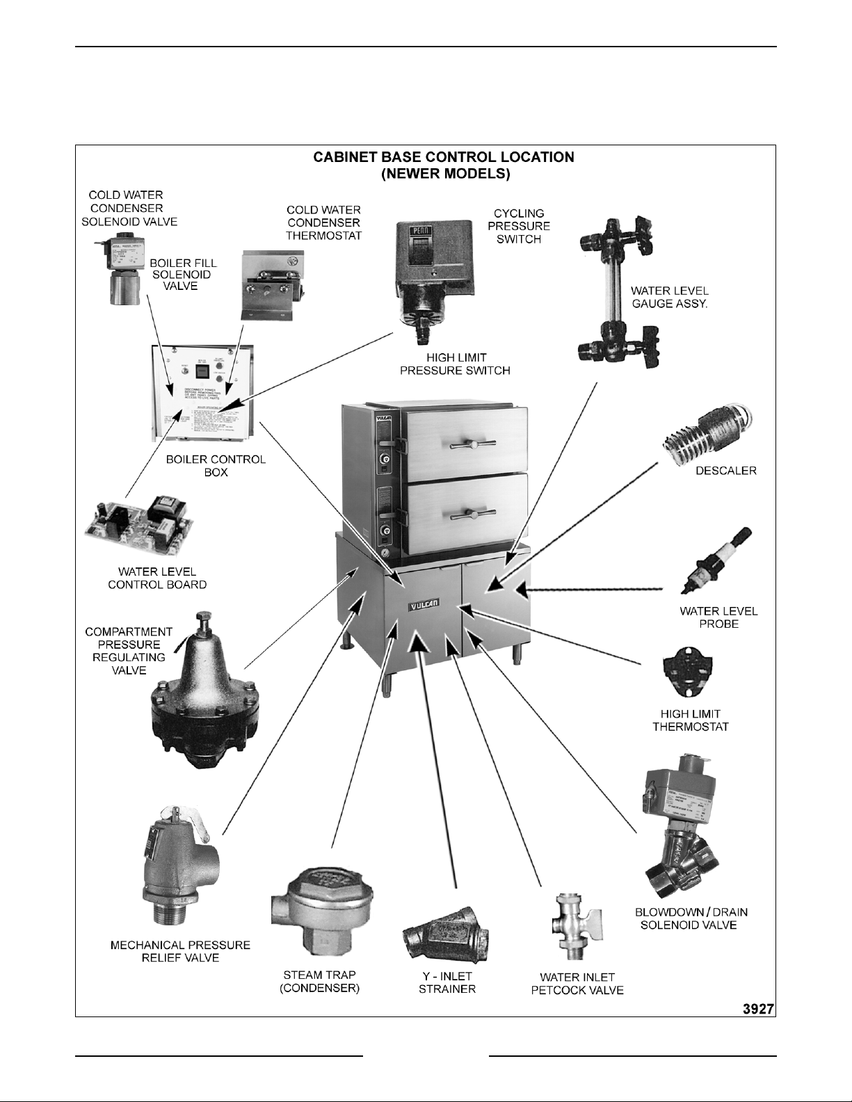
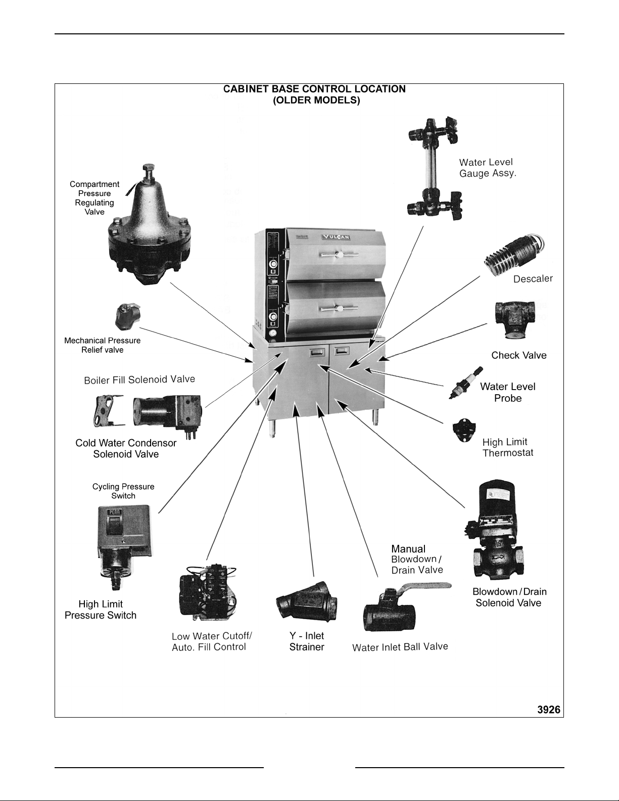
CABINET BASE BOILER CONTROLS
Water Level
Gauge Assembly ...............
Water Level Cont rol and
Level Sensing Probes ...........
VL SERIES STEAMERS - GENERAL
Permi ts a visual c onfirmation the water level is bein
boiler durin
ht of t he glass. The manual valves at t he top and bottom of this
hei
assembly must be full y open and only closed if the
dama
These controls allow water to enter the boiler to fill and maintain the
proper water level. T hey will also shut off the heat source to the boiler if
the water level drops too l ow. T he water level control works by usin
three different pr obe lengths to moni tor the water level. The probes
consist of a hi
operation. The correct water l evel is a point one-half of the
ed.
h level (HL), low level (LL) and low water cut-off (LLCO ) .
maint ained in
lass tube is
Boiler Fill Solenoid Valve ........
Cold Water Condenser
Solenoid Valve .................
Cycling Pressure Switch .........
High Limit Pressure Switch ......
Blowdown/Drain
Solenoid Valve .................
Inlet Water Strainer .............
Admits water to the boiler when dem anded by the water level control to
maintain the correct water level in the boiler.
Allows cold water flow into the boiler blowdown drain box to condense
steam and cool the hot water before its dischar
Controls boiler pressure between prescribed limits by tur nin
source on and off.
A switch of identical desi
h limit. T he pr essure settings are at higher and lower limits than t he
hi
cyclin
boiler pressure reaches its limit and autom atically resets after the
pressure drops below the lower limit set point.
This valve is plumbed into the drai n line of the boiler. Newer steamer
models will automatically blowdown when power is turned off by usi n
normally open solenoid valve. Older models can have a solenoid valve
that is activated by depressin
have a manual “ball” type valve.
A strainer i s used in t he water inlet l ine to prevent for ei
becomin
to keep unwanted partic les out of the system. A "Y" str ainer should be
inserted upstream of the fill solenoid valve. On models usin
steam supply, a str ainer is also used in the pressure re
pressure switch in order to tur n off the heat source before the
lodged in the fill or cold water condenser solenoid valves and
n to the cycling pressure switch but used as a
a separate blowdown timer button or
e into the drain.
the heat
n matter from
a direct
ulating valve.
a
Power Switch..................
Water Inlet Valve ...............
High Limit Thermostat ..........
Descaler ......................
When turned ON, power is supplied to the control s and the steam
enerating process is started in the boiler. The power switch is located
on the front of the boiler control box.
The water inlet valve is used to stop water flow to the steamer when the
steamer is bei n
valve while older models will be a “ball” type valve. This valve should
remain open dur in
A protective device that shuts off the heat source if the boiler
temperat ur e exceeds a specified limit. A ll standard m odels are equipped
with a surface hi
s submerged in water inside t he boiler and is used to hel p c ontrol
Han
boiler surface scalin
Page 11 of 88
servi c ed. Newer models will have a small Petcock type
normal oper ation.
h limit.
. Two descalers are used in each boiler.
Page 12

VL SERIES STEAMERS - GENERAL
g
g
g
g
g
g
g
g
g
g
g
g
g
g
g
g
g
g
g
g
g
g
g
g
Handhole Cover Assembly ....... When unbolted and removed, allows internal examination and cleanin
of boiler shell and i ts components if required.
Boiler Pressu re Gauge .......... Indicates the amount of steam pressure in the boiler.
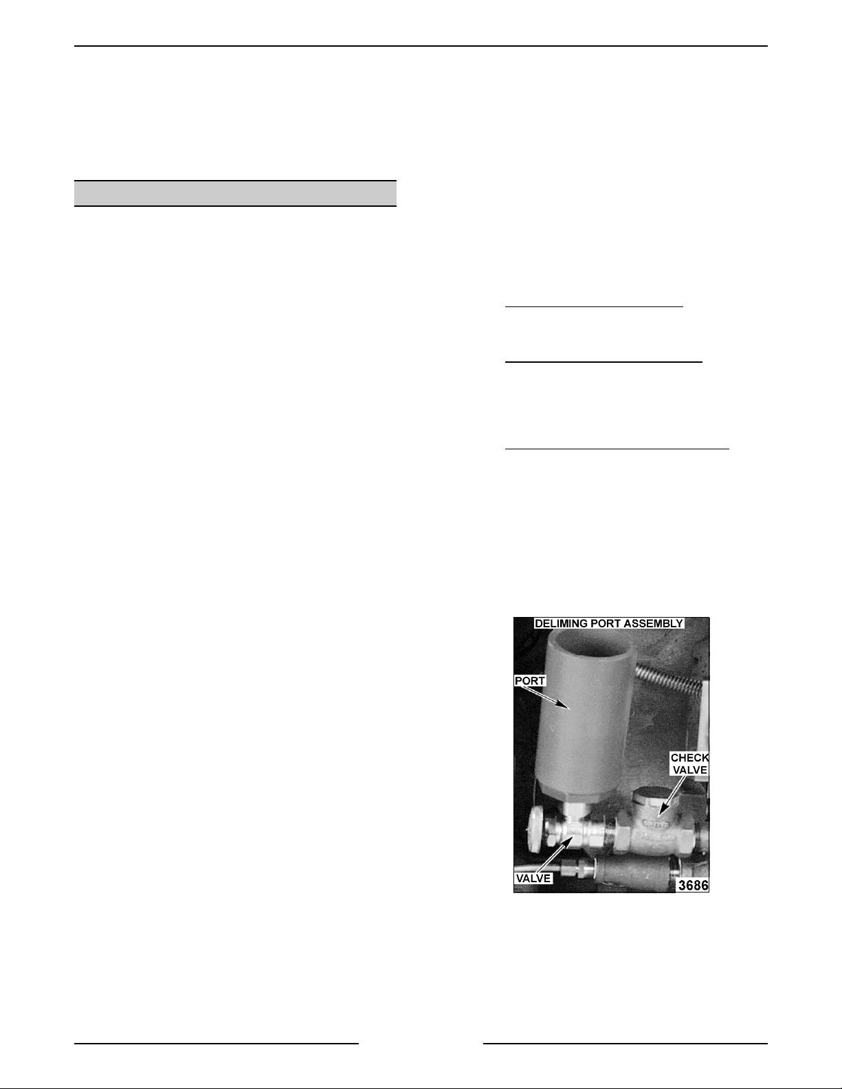
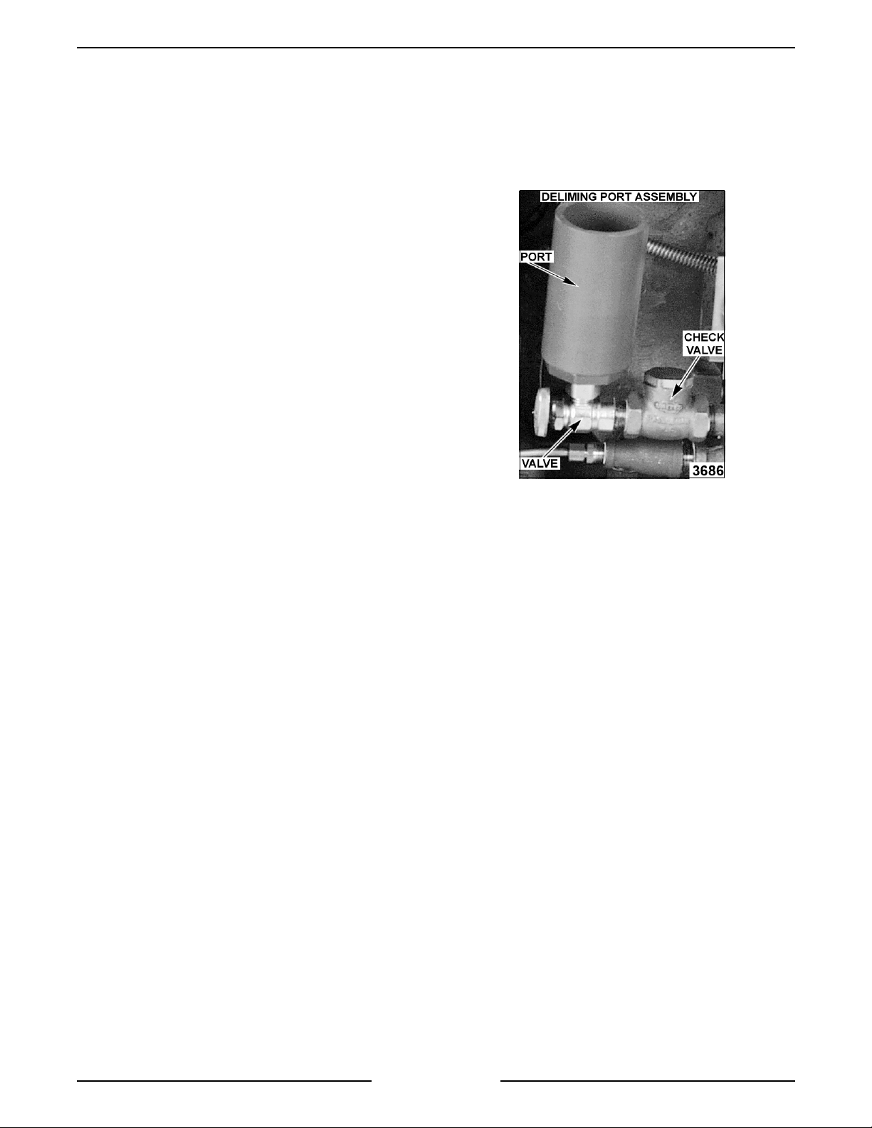
Check Valve ................... On models with the delime pipin
of hot water and steam out of the delime funnel if the manual delime fill
valve were to be opened.
Delime Port Assembl y ........... O n models with the delime pipin
other inter nal components to be delimed, easily removin
and rust build up.
Gas Pilot ..................... Shoul d always remain lit to li
ht the main burners upon a call for heat
unless the steamer will not be in use for an extended period. If the pilot
flame
oes out, wait 5 minutes before relighting.
Gas Burners................... Heats the water in the boiler to
Gas Combination Control Valve . . . A
as solenoid v alve that opens to allow gas flow when a call for heat is
made. Also re
ulates the m anifol d gas pressure and supplies the gas
pilot.
Transformer ................... Provides 24VAC power to i
electronic i
nition)
Ignition Control Module ......... Controls and monit or s
nition c ontrol module. (gas models with
as heating. Energizes pilot valve coil to supply
as to pilot, generates spark to ignite gas at the pilot, moni tors the
presence of flame and ener
supply
the
as to the mai n bur ner s. The pilot and main solenoi ds are part of
as combination control valve. (gas models with elec tronic ignition)
izes mai n valve coi l upon a call for heat to
Ignition Control Module
Reset (ON/OFF) Switch .......... Controls power to the i
module if the
nition)
i
as ignition exceeds trial tim e. (gas models with elec tronic
nition c ontrol module and allows a reset of the
assembly opti on, prevents the ejecti on
assembly opti on, allows the boil er and
calcium, lime
enerate steam.
Heater Contacto r
(Electric Bo ilers) ............... When coil is ener
ized, supplies power to the electric heating element s.
Heating Elements
(Electric Bo ilers) ............... Heats the water in the boil er to
enerate steam.
Steam Header Assembly ......... Main steam supply line fr om the boiler to the steam header inlet i n the
cookin
control compartm ent.
Pressure Relief V alve ........... A m ec hanical device that opens to relieve steam pr essure in the boiler if
the pressure exceeds 15 psi.
Compartment P ressure
Regulating Valve ............... Reduces steam pressure form t he boiler or bui ldin
enerated models) to supply the compartment s a steam pressure of 6
re
steam (dir ec t and
psi. Standard on PS , option on MS, S S and A S c ompartm ent controls.
Page 12 of 88
Page 13

VL SERIES STEAMERS - GENERAL
g
g
g
g
g
g
g
g
g
g
g
g
g
g
g
g
g
g
g
g
g
g
g
g
g
g
g
g
g
g
g
COOKING COMPARTMENT CONTROLS
The top half of t he steamer consists of two to three separate cooking compartments depending on the model .
Each compartment functions independently with i ts own set of controls. Power i s supplied to the controls throu
the compartment power switch and the cook in
models have a load compensatin
compartment reaches 180°F to close the switch.
thermal switch that prevents the contr ols from r ec eiving power until the
tim er c ontrol micro switch contacts. Prev ent and Automat ic
h
Compartment Power Switch......
Cooking Light (Red) ............
Cooking Timer .................
Buzzer .......................
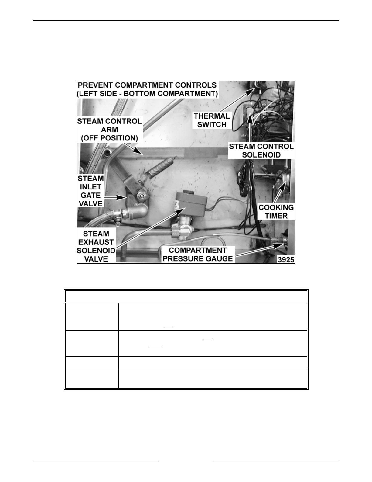
Steam Exhaust S olenoid Valve . . .
Steam Header Inlet (manifold) ....
Compartment P ressure Gauge ....
Steam Contro l Arm Solenoid .....
Supplies power to the cook in
When lit, indicates steam er is in a cookin
manual)
Use to set desired cookin
the buzzer when time expir es (All models except manual). On P r event
models, also de-ener
before the end of a cook cycle to allow compartment venti n
nals end of a cook cycle, must be turned of f manual ly. (All models
Si
except manual)
A normal ly open v alve that allows full com par tment ventin
condensate up to 180°F durin
vent in
remains closed to allow compar tment pressurization to 6 psi until one
minute before the end of a cook cycle at which point t he timer control
micro switch contacts (SW2) chan
vent the compartment of pr essure and steam . (prev ent models)
Main steam suppl y line f r om the boiler for each c ook in
Supplies steam to the manual steam
Indicates the amount of steam pressure in cookin
When ener
control arm off of t he c atch, all owin
closes the steam i nlet
valve. ( pr event, automati c and standar d models)
” after energized by the closing of the t her mal switch. The valve
ized, engages the lift arm ( plunger) to raise the steam
izes the steam exhaust solenoid valve one minute
compartment controls.
cycle. (All models except
cycle time between 0-60 minutes. Energizes
.
of air and
compartment heat up and “limited free
e state and de-energize the valve to
compartment.
ate v alves.
compartments.
it to return to its rear position. This
ate v alve and opens the steam exhaust gate
Thermal S witch
(Load Compensator) ............
Steam Gate Valves .............
Steam Trap ( Condenser) .........
Controls power to the preheat cycle components. Turns the cookin
on, ener
cookin
180(F. (prevent and automatic models)
Manual valves actuated by the steam control ar m. Allows steam to flow
into the cook in
the arm is in a forward position and exhaust the steam throu
exhaust steam
use a steam exhaust solenoid valve t o exhaust the steam and a si n
steam
manual models use one steam
one additional steam
Exhausts air and condensate from c ompartm ent durin
compartment temperature reaches approx imately 180(F. The bel lows
then close, stoppi n
izes the steam exhaust solenoid valve and energizes the
timer motor to start timing, aft er the compartment reaches
compartment through the inlet steam gate v alve when
ate v alve when the arm is at the rear . Prev ent models
ate v alve as the steam inlet. The automatic, standar d and
ate v alve to exhaust the steam and
ate v alve as the steam inlet.
preheat until the
the exhaust. ( all models except prevent)
light
h the
le
Page 13 of 88
Page 14
VL SERIES STEAMERS - REMOVAL AND REPLACEMENT OF PARTS
REMOVAL AND REPLACEMENT OF PARTS
COMPONENT LOCATIONS
Page 14 of 88
Page 15
VL SERIES STEAMERS - REMOVAL AND REPLACEMENT OF PARTS
Page 15 of 88
Page 16
VL SERIES STEAMERS - REMOVAL AND REPLACEMENT OF PARTS
g
g
g
COOKING COMPARTMENT CONTROLS - COMPONENT CONFIGURATIONS
1. Prevent
(shown above)
2. Autom atic same as prevent except does not
3. Standard same as automatic except does not include thermal switch.
4. Manual manual and exhaust steam
thermal switch, inlet steam
valve, steam control ar m solenoid, timer, buzzer and power switch
with li
valve but does
traps.
Includes two steam t r aps.
ht. Does not use a steam tr ap.
include an exhaust steam gate v alve and two steam
Page 16 of 88
ate v alve, steam exhaust sol enoid
include steam exhaust solenoi d
ate v alves and a manual timer.
Page 17

VL SERIES STEAMERS - REMOVAL AND REPLACEMENT OF PARTS
g
g
g
gaug
g
g
g
g
g
g
gauge g
g
g
g
g
g
g
g
g
WATER LEVEL CONTROLS -
LOW LEVEL CUT OFF AND
DIFFERENTIAL
WARNING:
POWER TO T HE MACHINE AT THE MAIN
CIRCUIT BO X. P LA CE A TAG ON THE CIRCUIT
BOX INDICATING THE CIRCUIT IS BEING
SERVICED.
Solid State
1. Open the cabinet base doors.
2. Remove the two screws at the top of the boiler
3. Water level control is mounted on the back
4. Disconnect lead wir es from the boar d and
5. Reverse procedur e to install and c hec k for
Electro Mech anical
DISCONNECT THE ELECTRICAL
control box and allow cover to drop down.
side of cover.
remove the water level control.
proper operation.
4. Slide t he
the tube is cl ear of the fittin
5. When r einstallin
washers. Do not over tighten the packi ng nuts;
it coul d br eak the
6. Open the top and bottom valves and check for
proper operation.
lass tube upwards until the bot tom of
and lift it out.
the tube use new sealin
lass.
CYCLING AND HIGH LIMIT
PRESSURE SWITCHES
(GAS AND ELECTRIC MODELS)
WARNING:
POWER TO T HE MACHINE AT THE MAIN
CIRCUIT BO X. P LA CE A TAG ON THE CIRCUIT
BOX INDICATING THE CIRCUIT IS BEING
SERVICED.
1. Open the cabinet base doors and remov e the
left side panel.
2. Remove the two screws at the top of the boiler
control box and allow cover to drop down.
DISCONNECT THE ELECTRICAL
1. Open the cabinet base doors.
2. Remove the two screws from t he left and r i
side of the water level control box and lift cover
off.
3. Disconnect lead wir es from the c ontrol bein
replaced and remove.
4. Reverse procedur e to install and c hec k for
proper operation.
ht
WATER LEVEL GAUGE
ASSEMBLY
WARNING:
POWER TO T HE MACHINE AT THE MAIN
CIRCUIT BO X. P LA CE A TAG ON THE CIRCUIT
BOX INDICATING THE CIRCUIT IS BEING
SERVICED.
1. Open the cabinet base doors and remov e the
2. Close the valve at the top and at the bottom of
3. Unscrew the packin
DISCONNECT THE ELECTRICAL
ht side panel.
ri
the
of the
e assembly.
nuts at the top and bottom
lass tube.
3. The pressure switches are located at the rear of
the box. The pressure switch on the ri
cyclin
the hi
switches, dif ferin
4. Remove the cover from the pressure switch
bein
5. Disconnect the pressure fittin
of the switch.
6. Remove the mount in
of the control box and lif t out the pressure
switch.
7. Preset the new pressure switch to the
approximate cut-out (off) and cut-i n ( on) set
points before installin
chart under “CYCLI NG AND HIGH LIMIT
PRESSURE SWITCHES (GAS AND
ELECTRIC MODELS)” in “SERVICE
PROCEDURES AND ADJUSTMENTS”.
8. Reverse procedur e to install .
9. Adjust the pressure switch(s) final set poi nts as
outlined under “ CY CLING AND HIGH LI M IT
PRESSURE SWITCHES (GAS AND
ELECTRIC MODELS)” in “SERVICE
PROCEDURES AND ADJUSTMENTS” and
check for pr oper oper ation.
or prim ar y c ontrol; the one on the left is
h limit contr ol. They are identical
only in t heir settings.
replaced and disconnect the lead wires.
s at the bottom
screws on the back side
. See the boiler pressure
ht is the
Page 17 of 88
Page 18

VL SERIES STEAMERS - REMOVAL AND REPLACEMENT OF PARTS
g
g
g
g
g
g
g
g
g
g
g
g
g
BOILER ASSEMBLY
WARNING:
POWER TO T HE MACHINE AT THE MAIN
CIRCUIT BO X. P LA CE A TAG ON THE CIRCUIT
BOX INDICATING THE CIRCUIT IS BEING
SERVICED.
WARNING:
SERVICING THE UNIT.
WARNING:
DURING SERVI CING MUST BE CHE CK E D FOR
LEAKS. CHECK WITH A SOAP AND WATER
SOLUTION (BUBBLES). DO NOT USE AN OPEN
FLAME.
1. Blow down the boiler and allow to cool, if
2. Ensure that all utilities to the steamer are off
3. Disconnect the steam supply li ne, power leads
4. Disconnect all plumbin
5. Disconnect the remainin
6. Remove the screws holdin
7. Remove the anchor screws holdin
DISCONNECT THE ELECTRICAL
SHUT OFF THE GAS BEFORE
ALL GAS JOINTS DISTURBED
necessary.
and disconnected. Drain any excess water fr om
the boiler .
and drain lines from the cookin
top to the boi ler base.
connections and power
leads from the components inside the control
boxes that would obstruct the removal of the
boiler throu
remove those control boxes.
electrical connections from the boiler t o the
controls.
collector to the base.
the frame. Slide the boil er forward. The burner
box, anchored only by the boiler, must be
prevented from slidin
h the front of the base, t hen
forward with the boiler.
compartment
plumbing and
the flue and flue
the boiler to
HIGH LIMIT THERMOSTAT
WARNING:
POWER TO T HE MACHINE AT THE MAIN
CIRCUIT BO X. P LA CE A TAG ON THE CIRCUIT
BOX INDICATING THE CIRCUIT IS BEING
SERVICED.
1. Open the cabinet base doors.
2. Electric model s onl y - for
to step 3.
A. Newer Models
B. Older Models
3. Gas Models only.
A. Remov e the thermostat c over which is
4. Reverse procedur e to install and c hec k for
proper operation.
DISCONNECT THE ELECTRICAL
as models proceed
- are not equipped wit h a hi
limit thermostat but rely on the Hi l imit
pressure switch instead.
- the high limit thermostat is
located behi nd the contactor box cov er .
On electr ic boiler s with two heatin
element s, the thermostat is connected to
one of the heat in
electric boilers with four heati n
the therm ostat is located on an aluminum
plate between the cent er pair of elements
at the top of the elements. Remove the
thermostat lead wires and mounti n
replace thermostat and check for proper
operation.
located on the front of the boil er .
Disconnect the t her mostat lead wires and
remove the nuts securin
thermostat to the boiler surface.
element lugs. On
element s,
nuts,
the high limit
8. Reverse procedur e to install a new boiler and
check for leaks and proper operation.
Page 18 of 88
Page 19

VL SERIES STEAMERS - REMOVAL AND REPLACEMENT OF PARTS
g
g
g
g
g
g
g
g
g
BOILER FILL AND COLD WATER
CONDENSER SOLENOID VALVES
WARNING:
POWER TO T HE MACHINE AT THE MAIN
CIRCUIT BO X. P LA CE A TAG ON THE CIRCUIT
BOX INDICATING THE CIRCUIT IS BEING
SERVICED.
1. Turn off the water supply t o the steamer.
2. Open the cabinet base doors and remov e the
3. Disconnect the power lead wir es from the
4. Disconnect the water lines for t he valve bein
5. Reverse procedur e to install .
DISCONNECT THE ELECTRICAL
two screws at the top of the boiler control box
and allow cover to drop down. Both solenoid
valves are l oc ated side by side near the front of
the boiler control box with the boiler fill on the
ht and the cold water c ondenser t o the left.
ri
solenoid valve bein
servi c ed and r emov e the valve.
servi c ed.
PILOT AND THERMOCOUPLE
ASSEMBLY ( GAS MODELS)
WARNING:
POWER TO T HE MACHINE AT THE MAIN
CIRCUIT BO X. P LA CE A TAG ON THE CIRCUIT
BOX INDICATING THE CIRCUIT IS BEING
SERVICED.
WARNING:
SERVICING THE UNIT.
WARNING:
DURING SERVI CING MUST BE CHE CK E D FOR
LEAKS. CHECK WITH A SOAP AND WATER
SOLUTION (BUBBLES). DO NOT USE AN OPEN
FLAME.
DISCONNECT THE ELECTRICAL
SHUT OFF THE GAS BEFORE
ALL GAS JOINTS DISTURBED
GAS COMBINATION CONTROL
VALVE
WARNING:
POWER TO T HE MACHINE AT THE MAIN
CIRCUIT BO X. P LA CE A TAG ON THE CIRCUIT
BOX INDICATING THE CIRCUIT IS BEING
SERVICED.
WARNING:
BEFORE SERVICING THE UNIT.
WARNING:
DURING SERVI CING MUST BE CHE CK E D FOR
LEAKS. CHECK WITH A SOAP AND WATER
SOLUTION (BUBBLES). DO NOT USE AN OPEN
FLAME.
NOTE:
servi c eable and should not be disassembled. Once
the problem has been isolated to this control,
replace it. Do not attempt to repair the assembly.
1. Open the cabinet base doors and remov e the
two screws at the top of the boiler control box
and allow cover to drop down.
2. Disconnect elec trical suppl y wir es and conduit
runnin
3. Disconnect the t her mocouple l ead ( if
applicable), pil ot
and pipe connections on each side of the
control.
4. Reverse procedur e to install .
5. Set manifold pr essure as outlined under “GAS
MANIFOLD PRESSURE ADJUSTMENT” in
“SERVICE PROCEDURES AND
ADJUSTMENTS”.
6. Check for pr oper oper ation.
DISCONNECT THE ELECTRICAL
SHUT OFF THE GAS SUPPLY
ALL GAS JOINTS DISTURBED
Gas combination control valves are not
to the com bination cont r ol valve.
as supply tube from control
1. Open the cabinet doors to access the pilot and
thermocouple assembly. T he assembly is
located to the ri
half way back from the front.
2. Disconnect thermocouple and pi lot
from the combination contr ol valve.
tubin
3. Remove the two screws holdin
bracket.
4. Replace the ther mocouple or pilot assembly
and check for pr oper oper ation.
ht of t he c enter burner and
as supply
the pilot to its
Page 19 of 88
Page 20
VL SERIES STEAMERS - REMOVAL AND REPLACEMENT OF PARTS
g
g
g
g
g
g
g
g
g
g
g
g
g
g
g
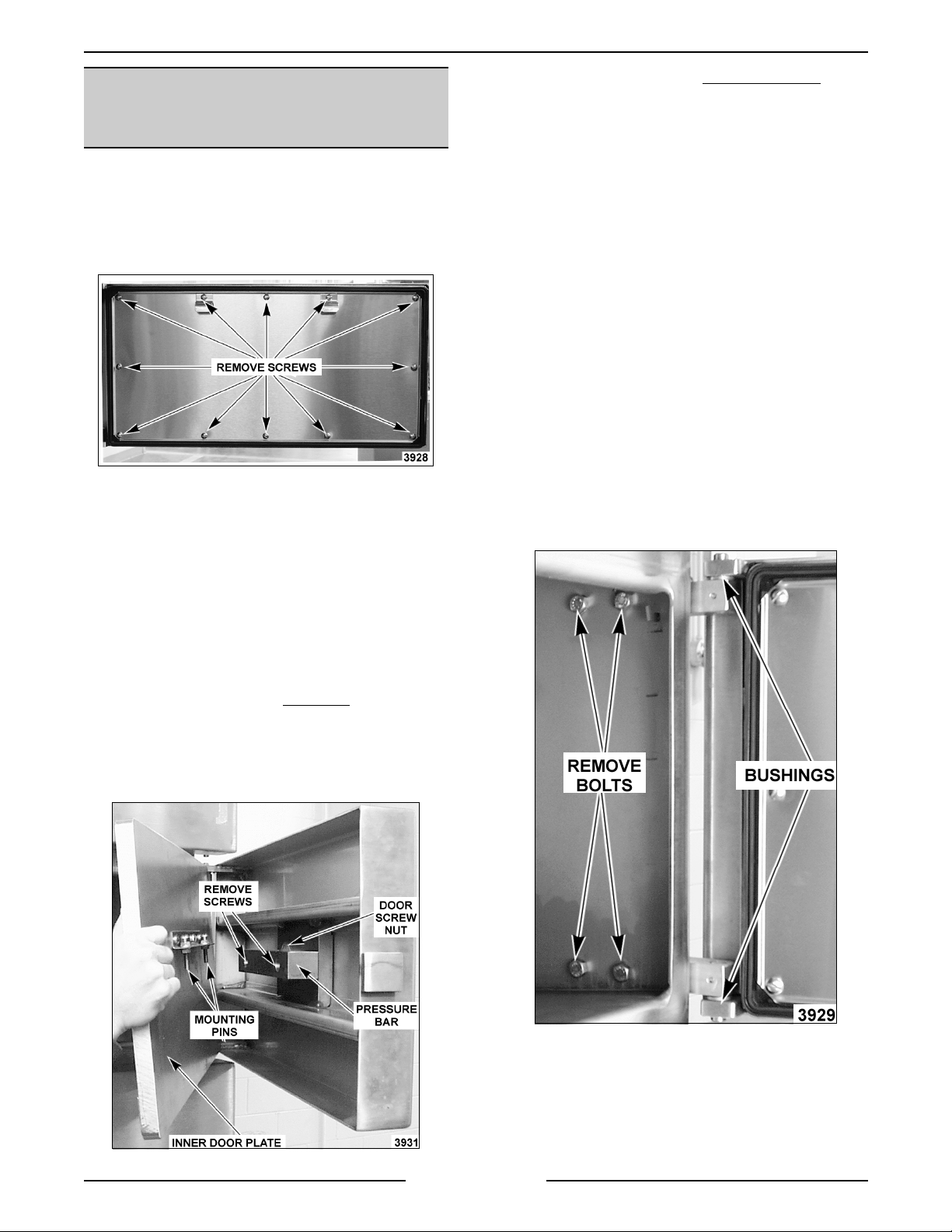
COMPARTMENT GASKET AND
DOOR SCREW NUT, DOOR AND
BUSHINGS
Gasket
1. Open the com par tment door t o be r eplaced.
2. Remove screws securin
plate to t he gasket.
3. Lift the
4. Position t he new
and rever se procedur e to install .
asket off the inner door plate.
the gasket retainin
asket on the inner door plate
4. Turn screw handle fully counter c lockwise
remove from door.
5. Remove screws mountin
the backside of the compartment door.
NOTE:
each screw. Set aside f or r euse.
6. Remove screws mountin
7. Reverse procedur e to install and c hec k for
Door and Bushing
1. Open the com par tment door t o be r eplaced.
2. Remove the ri
3. Remove the four bolts inside the compartm ent
CAUTION: Door is extremel y heavy and will drop
when bolts are removed.
A compression sprin
(bronze) to the bac k si de of the compartment
door.
proper operation.
ht side pan support inside the
compartment.
that secure the bl oc k hin
of the compartm ent.
the pressure bar to
is mounted behind
the door screw nut
es to the exter ior side
and
NOTE:
as nicks or cuts, will cause steam leaka
Door Screw Nu t
1. Open compartment door t o be serviced.
2. Turn screw handle fully cl oc k wise
3. Lift the inner door plate assembly up, until the
Dama
inner door plate assembly.
mounti n
pressure bar and set the assembly aside.
e to the gasket sealing surface, such
e.
to extend
pins are out of the holes in the
4. At this time, t he bushi n
necessary, by removin
pin on each block hin
5. Reverse procedur e to install and c hec k for
proper operation.
Page 20 of 88
s can be replaced if
the bushings from the
e.
Page 21

VL SERIES STEAMERS - REMOVAL AND REPLACEMENT OF PARTS
g
g
g
g
g
ge g
g
g
g
g
g
g
g
HEATER CONTACTORS
WARNING:
POWER TO T HE MACHINE AT THE MAIN
CIRCUIT BO X. P LA CE A TAG ON THE CIRCUIT
BOX INDICATING THE CIRCUIT IS BEING
SERVICED.
1. Open the cabinet base doors, remove the two
2. Disconnect the electrical lead wires to the coil
3. Remove the screws form the base of the
4. Reverse procedur e to install and c hec k for
DISCONNECT THE ELECTRICAL
screws from the contactor box c over and l ift
cover off.
and the power supply wires from the contact or
bein
replaced.
contactor and lift out.
proper operation.
HEATING ELEMENTS
REGENERATED STEAM MODELS
(STEAM COIL)
WARNING:
POWER TO T HE MACHINE AT THE MAIN
CIRCUIT BO X. P LA CE A TAG ON THE CIRCUIT
BOX INDICATING THE CIRCUIT IS BEING
SERVICED.
WARNING:
BEFORE SERVICING THE UNIT.
1. Disconnect pipe unions in the steam suppl y line
to the coils and in the condensate dischar
line from the c oils.
2. Remove header that supplies steam to the coils
by disconnecti n
3. Remove coil c ondensate c ollection header.
4. Remove bolts securin
and pull coil for ward.
5. Clean the m atin
flan
DISCONNECT THE ELECTRICAL
SHUT OFF THE STEAM SUPPLY
e
union at each coil.
the coil being replaced
surfaces of the steam coil
e and the boiler .
WARNING:
POWER TO T HE MACHINE AT THE MAIN
CIRCUIT BO X. P LA CE A TAG ON THE CIRCUIT
BOX INDICATING THE CIRCUIT IS BEING
SERVICED.
1. Open the cabinet base doors, remove the two
2. Disconnect the electrical lead wires to the
3. Remove the bolts securi n
4. Clean the m atin
5. Check for leaks and proper operation.
DISCONNECT THE ELECTRICAL
screws from the contactor box c over and l ift
cover off.
element bein
e to the boiler and lift the el ement out.
flan
install a new flan
element .
replaced.
the heating element
surface of the boiler and
asket and heatin
6. Reverse procedur e to install a new steam c oil
asket.
and
7. Check steamer for proper operation.
Page 21 of 88
Page 22
VL SERIES STEAMER - SERVICE PROCEDURES AND ADJUSTMENTS
g
ging
g
g
g
g
g
g
g
g
g
g
g
g
g
g
g
g
g
g
g
g
g
g
g
g
g
g
g
g
g
g
g
SERVICE PROCEDURES AND ADJUSTMENTS
WARNING: CERTAIN PROCEDURES IN THIS SECTION REQUIRES ELECTRICAL TEST OR
MEASUREMENTS WHILE POWER IS APPLIED TO THE MACHINE. EXERCISE EXTREME CAUTION AT ALL
TIMES. IF TEST POI NTS ARE NOT EASI LY ACCESSIBLE, DISCONNECT POWER, ATTACH TEST
EQUIPMENT AND REAPPLY POWER TO TEST.
BOILER
Inspection
It is recommended the boiler be inspected for
excessive scale and li me build up on a quar terly
basis. In hard water areas or f or steamers heavily
used, a more frequent inter val shoul d be used. This
inspection consi sts of an internal examination and
cleanin
han
water level probes. Also, a c hec k of all boiler
controls, includin
Periodic service must be perfor med as outlined in
these procedures. See “WATER CO NDITIONING”
under “GENERAL”.
WARNING: READ AND FO LLOW THE
INSTRUCTIONS ON THE CLR BOTTLE. USE
PLASTIC OR RUBBER GLOVES TO AVOID SKIN
CONTACT. I F CLR LIQUID COMES IN CO NTACT
WITH THE SKIN, RINSE WITH CLEAN WATER.
Clean-Out (All Boiler Models)
1. Turn steamer OFF and drain boiler.
2. Remove hand hole plat e and
of the boiler, an examinat ion of the two
descalers, and for lime build up on the
the pressure switches.
asket (top f r ont)
from the boiler by r emov in
then tappin
holdin
from droppin
the cover lightly to free it while
the cover stud. This prevents the cover
into boiler.
the nut and clamp,
NOTE: B oiler water capacities vary between seven
to nine
dependin
NOTE: If delimin
contact with steamer components, li
with clean water.
allons f or both gas and electric models
on the boiler si z e and B TU/KW rating.
solution accidently comes in
htly rinse off
A. M odels with Blowdown Timer
delimin
to step 9.
B. M odels without Blowdown Timer
the incomin
switch ON to cl ose the dr ain valve. Pour
delimin
to step 9.
C. Models with Delimin
Before pourin
boiler, c lean the seatin
hand hole
asket. Position the hand hole plate and
ti
supply. Turn t he power switch O N to close
the drain valve. Open t he delimin
assembly valve and pour the delimin
solution i nto the port. Close the delimin
assembly valve and proceed to step 10.
solution into boiler shell. Proceed
water supply. Turn t he power
solution into boiler shell. Proceed
Port Assembly -
deliming solution into
asket and then instal l a new
hten down. Turn of f the inc oming water
- Pour
surfaces for the
- Turn off
springs if
used.
e and
Page 22 of 88
9. Clean the seatin
asket and then Install a new gasket. Position
hten the hand hole plate.
and ti
surfaces for the hand hole
3. Remove old descaler retainin
present.
4. With a wire brush, or equi valent, dislod
remove all loose scale from boiler shel l. The
loose material must be either scooped fr om the
h the drain.
boiler or flushed throu
5. Check probe canister and float valve assembly
enerated models) for a scale build up and
(re
clean as necessary.
6. Check drain hol e for obstructions.
7. Inspect the condi tion of the descalers as
outlined in this section and r eplace if
necessary.
8. Mix the delimin
instructions for the chemical bein
solution according to the
Page 23
VL SERIES STEAMER - SERVICE PROCEDURES AND ADJUSTMENTS
g
g
g
g
g
g
g
g
g
g
g
g
g
g
g
g
g
g
g
g
g
g
g
ging
g
g
10. Cooking compartment ti mers are to be in t he
OFF position. Turn the boiler switch ON and
open water valve if necessary.
11. Boiler is to operate under pressure for 90
minut es or per the instructions for the chemical
in use.
12. Drain boiler by normal methods.
13. Refill boiler and allow to heat until fully
pressurized.
14. Repeat step 13 three times.
15. The steamer is now ready for norm al operation.
Deliming Only (Models with Deliming Port
Assembly)
Boiler delimin
bi-weekly or monthly basis, dependin
should be performed on a weekly,
on the quality
of the local water supply. S ee “ WAT E R
CONDITIONING” under “GENERAL”.
On steamers usin
a water purif ication system,
follow the instructions for that system to deli me the
boiler. Only use the type of chemical recommended
or described in t he instructions for delimin
with this
type of system.
1. Turn steamer OFF and drain boiler.
2. Mix the delimin
instructions for the chemical bein
solution according to the
used.
NOTE: B oiler water capacities vary between seven
to nine
dependin
NOTE: If delimin
contact with steamer components, li
allons f or both gas and electric models
on the boiler si z e and B TU/KW rating.
solution accidently comes in
htly rinse off
with clean water.
A. Models with Blowdown Timer - Open
the delimin
delimin
delimin
assembly valve and pour the
solution i nto the port. Close the
assembly valve and proceed to
step 3.
B. Models without Blowdown Timer - Turn
off the incomin
water supply. Turn t he
power switch ON to close the drain valve.
Open the delimin
pour the deli min
Close the deli min
assembly valve and
solution i nto the port.
assembly valve and
proceed to step 3.
3. Top compartments are to be in the OFF
position. Turn the boil er switc h ON and open
water valve if necessary.
4. Boiler is to operate under pressure for 90
minut es or per the instructions for the chemical
in use.
5. Drain boiler by normal methods.
6. Refill boiler and allow to heat unti l ful ly
pressurized.
7. Repeat step 6 three times.
8. Steamer is now ready for norm al operation.
Descaler
The descaler is accessible throu
openin
cylindr ical core, and han
. It i s a coiled wire wound around a solid
s by an open loop from the
h the hand hole
shell's horizontal stay rod, about 4 inches from the
front of the shell . If t he wir e is eaten throu
h, or if
the core of the descaler is eaten away to hal f its
inal size, a new descaler should be installed.
ori
To install a new descaler, stretch its wire coil so the
descaler han
minimum water level in the boi ler, but han
s with its core completely below the
free.
The descaler m ust not contact the bottom of the
boiler shell, elect r ic heatin
enerating steam coils.
re
element s or
Page 23 of 88
Page 24

VL SERIES STEAMER - SERVICE PROCEDURES AND ADJUSTMENTS
g
g
g
g
g
g
g
g
g
gaug
g
g
g
g
g
g
g
g
gg
g
g
g
g
g
g
g
g
g
g
g
g
g
g
g
g
g
g
g
gaug
g
g
g
g
g
WATER LEVEL CONTROL(S)
TEST
Loose electric al connections may prev ent the heat
from comin
An accumulation of lime scale on or near the water
level sensin
water (moist) on the probe surface and
readin
ive a false reading. These conditions may prevent
the boiler from fillin
will result in damage to the heati ng element s on
electric models or t o the boiler on
models.
WARNING:
POW E R TO BE APPLIED TO THE UNIT DURING
THE TEST. USE EXTREME CAUTION AT ALL
TIMES.
Solid State - Low level Cut-Of f & Differential
Control
1. Turn the power switch ON.
2. Ensure that water is fillin
A. Confirm that water supply valve(s) are
B. Observe boiler water level in the water
3. Check the volta
the board. Meter shoul d r ead 120V A C.
A. If volta
B. If boiler fill solenoid is receivin
C. If boiler fill solenoid is not
4. If boiler is fillin
reaches the low level cut- off ( LLCO) probe,
LLCO relay should ener
contacts, heat source shoul d c ome on
(standard model s onl y ) and LLCO LED will
li
on or may cause the boiler to overfill.
probes may cause them to retain
ive a false
. Also, a crac k ed or damaged insulator may
or cause dry firing. Dry firin
as or electri c
THE FOLLOWI NG ST EPS REQUIRE
the boiler .
turned on.
level
approximately 11 minutes.
(HL) relay should ener
contacts and the HL LED should li
The boiler fill solenoid should then
ener
boiler fill solenoid valve is receivin
120VAC and water is flowing through it.
no water is fl owin
malfunction or valve for clo
solenoid is bad or port s can not be
cleaned, then r eplace boiler fill solenoid
and check for pr oper oper ation.
and the electr ical connect ions have been
checked, then t he HL r elay is not bein
energized or the HL-3 c ontacts are not
closin
and check for pr oper oper ation.
ht.
e. If empty, boiler should f ill in
e across terminals L1 & L2 on
e is correct t hen the high level
ize, closing HL-3
ht up.
ize and start filling the boiler. Verify
power but
, inspect fill solenoid for
ed ports. If
receiving power
. Replace water l evel c ontrol board
properly, when the water level
ize closi ng LLCO-2
5. Once the water level r eac hes the hi
(HL) probe, the inverse l atchin
board (solid state) shoul d ener
throu
h the low level probe (LL) and ILR-1
contacts. Wit h ILR-2 contacts open, t he HL
relay is de-ener
With the HL-3 cont ac ts open, the boiler fil l
solenoid should de-ener
fill.
6. If water is in the boil er but is not bein
by the water level probes, t he pr obes may need
cleaned and/or boiler delimed. See “Water
Level Probes” as outlined below for inspectin
and cleaning of probes and “BOILER” for a
procedure on boil er inspection, clean-out and
delimin
7. Turn the power switch OFF and disconnect the
lead wire f r om each probe. Check the probes
as outlined bel ow.
A. Wi th an ohmmeter, check between the
NOTE:
water quality and pr obe c ondition.
8. After performin
water level control boards operation, if the
control is not functionin
replace it and check for pr oper oper ation.
Electro Mechanical - Low level Cut-Off &
Differenti al Control
WARNING:
POW E R TO BE APPLIED TO THE UNIT DURING
THE TEST. USE EXTREME CAUTION AT ALL
TIMES.
1. Ensure that water is fillin
A. Confirm that water supply valve(s) are
B. Observe boiler water level in the water
C. Verify boiler fill solenoid valve is receivin
2. Check for correct volta
low level and different ial water level controls.
A. Turn the water supply valve off then turn
.
probe terminal and boiler shell. An open
circui t should be present when the boiler is
empty. If resistance is present, remove
and inspect the probes as outlined below
under “Water Level Probes”. When the
boiler is full of water, a resistance r eadin
should be measurable bet ween the probes
and boiler.
The actual r esi stanc e r eadin
THE FOLLOWI NG ST EPS REQUIRE
turned on.
level
120VAC and water is flowing through it.
the power switch ON. Check t he input
volta
should read 120VAC. If volta
proceed to step 2B. I f volta
find the source of the problem and repeat
this step.
ized and HL LED goes out.
ize and stop the boi ler
steps 1-5A and verifying the
as described, then
the boiler .
e.
e being applied to the
e across terminals 1 & 2. Meter
h level
relay of the
ize and lock
detected
will depend on
e is correct
e is incorrect,
Page 24 of 88
Page 25

VL SERIES STEAMER - SERVICE PROCEDURES AND ADJUSTMENTS
g
g
g
g
g
g
g
g
g
g
g
g
g
g
g
g
g
g
g
g
g
g
g
g
g
g
g
g
gaug
g
g
B. Wi th the boiler empty, chec k the voltage
across terminals 9 & 10. Meter should
read 300 to 350VAC. I f volta
proceed to step 3. If volta
approximately 30V A C then the internal
contactor is ener
scaled ov er and moist and/or have a
dama
See “Water Level Probes“ listed below for
inspectin
procedures on boiler inspection, clean-out
and delimin
volta
level control is bad and the control should
be replaced. Check for proper operat ion
after r eplacement.
3. If water is in the boil er but is not bein
by the water level probes, t he pr obes may need
cleaned and/or boiler delimed. See “Water
Level Probes“ listed below for inspectin
cleanin
boiler inspection, clean-out and deli min
4. Turn the power switch OFF and disconnect the
lead wire f r om each probe. Note the locati on of
the probes and the number of the wire
connected to i t.
A. Chec k the resistance between the probe
terminal and boil er shel l. An open
should be present when the boiler is
empty. If resistance is present, remove
and inspect the probes as outlined below
under “Water Level Probes”. A resi stanc e
readin
between the probes and boiler shell
(
NOTE: The actual resistanc e r eadin
water quality and pr obe c ondition.
5. If after performi n
not functionin
controls operation as outlined in “W A TER
LEVEL CONTROLS” under “ELECTRICAL
OPERATION”.
6. After checkin
cut off or differential water l evel c ontrol does
not appear to be functioni n
replace the control and check for proper
operation.
Water Level Prob es
WARNING: DISCONNECT THE ELECTRICAL
POWER TO T HE MACHINE AT THE MAIN
CIRCUIT BO X. P LA CE A TAG ON THE CIRCUIT
BOX INDICATING THE CIRCUIT IS BEING
SERVICED.
ed insulator giving a false reading.
and cleaning and “BOILER” for
e, then contactor coil on the water
and “BOILER” for procedures on
should only be m easurable
round) when the boiler is full of water.
properly, veri fy the water l evel
the abov e items, if the low level
ized but the pr obes are
. If y ou do not read any
steps 1-4 and the control is
as described, then
e is correct
e reading is
detected
and
.
circuit
will depend on
2. If lime scal e build up is evident on t he pr obe,
thorou
the probe and insulat or . Do not
abrasiv e on the insulator; use a sof t cloth.
3. Inspect the probes f or a c r ac k ed or dama
insulator. If a probe appears to be dama
replace it with a new one and proceed to step
5. If a pr obe does not appear to be dama
then proceed to step 4.
4. Check throu
top of t he c anister assembly for the presence of
water. Water must drain from the probe
canister and if in doubt, pour water into the
canister and observe that it drains quickly. If
water fails to drain from the canister, rem ove
the cover or canister assembly and clean.
5. Reverse procedur e to install and c hec k for
proper operation.
hly clean it removing all deposit s from
use any thin
ed
ed,
ed
h the probe socket opening in the
CYCLING AND HIGH LIMIT
PRESSURE SWITCHES
(GAS AND ELECTRIC MODELS)
WARNING: THE FOLLOW I NG ST EPS REQUIRE
POW E R TO BE APPLIED TO THE UNIT DURING
THE TEST. USE EXTREME CAUTION AT ALL
TIMES.
Remove the boil er c ontrol box c over as outl ined
under “CYCLING AND HIGH LI MI T PRESSURE
SWIT CHES (GAS AND ELECTRIC MODELS)” to
access the two controls. The pr essure switch on the
ht is the cycling or prim ar y c ontrol; the one on the
ri
left is the hi
switches, dif ferin
Turn the power ON and let the boiler c ome up to
pressure. Close and seal one of t he c ompartm ent
doors, set a time past 5 minut es on the c ook in
tim er , pull the steam control ar m handle forward and
turn the compartment power switch O N to exhaust
pressure from the boiler. Observe boi ler pressure
e readings for several cycles and compare
them with the pressure settin
If t he r eadin
described below.
h limit contr ol. They are identical
only in t heir settings.
s in the chart.
s differ, adjust t he pr essure settings as
1. Remove the cover ov er the water level probes
and disconnect the lead wire from each probe.
Note the location of eac h pr obe and the
number of the wire connected t o it. Rem ove
each water level probe for exam ination.
Page 25 of 88
Page 26
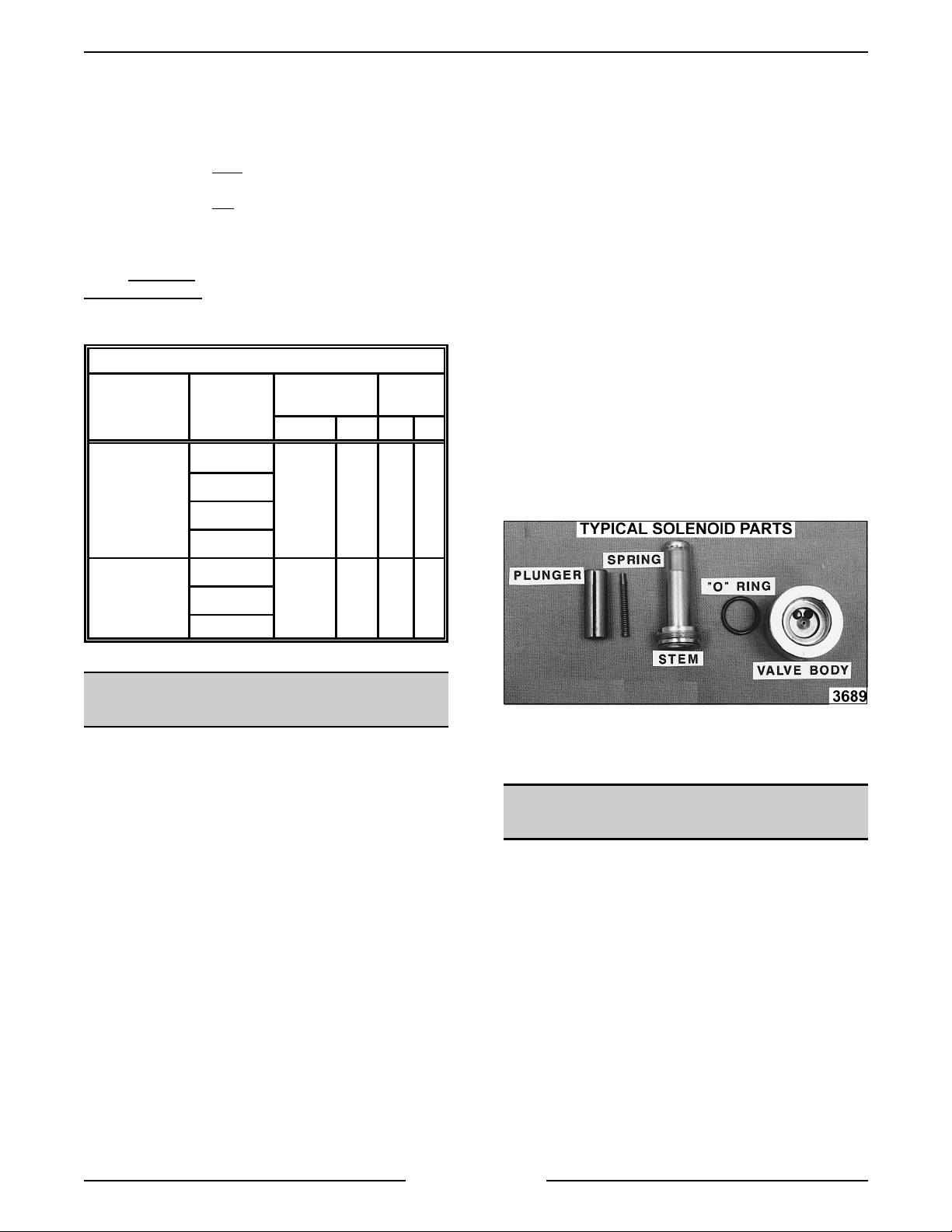
VL SERIES STEAMER - SERVICE PROCEDURES AND ADJUSTMENTS
g
g
g
g
g
g
g
g
g
g
g
g
g
gg
g
g
g
g
g
g
g
g
g
g
g
g
g
g
g
g
gaug
g
Two slotted and square headed adjustment screws
extend thr ou
pressure scale and indicat in
h the sight glass window to indicate t he
throu
approximate pressure settin
directly above the ri
h the top of the switch case. A
pointers are visibl e
. The adjustment screw
ht side pointer c hanges the
cut-out (off) set point and the adjustment screw
directly above the left
side pointer changes cut-in
(on) set point. A djust the screw to obtain t he pr oper
cut-out (off) settin
to obtain t he pr oper c ut-in (on) settin
screw clockwise
countercloc k wise
The pressure settin
fir st, then adjust the ot her screw
. Turn the
to increase the pressure setting and
to decrease the pressure setting.
s for each switch are listed
below.
BOILER PRESSURE SETTINGS (PSI)
CONTROL
TYPE
With
Compartment
Pressure
Regulating Valve
VL
MODELS
PS
AS
SS
MS
CYCLING HIGH
LIMIT
ON OFF ON OFF
911615
1. Remove the coil assembly f r om the valve stem
by liftin
the solenoid valve and slidin
up on the retaining cap at the top of
the metal cover
plate off.
2. Clamp t he body of the valve in a vise.
3. Mark a scribe l ine on the stem nut to the v alve
body for proper r eti
4. Remove the stem lockin
htening.
nut to remove the
stem f r om the valve body.
5. All parts are now accessible for i nspect ion and
cleanin
NOTE:
dama
Do not reuse dama
.
If internal solenoid parts appear to be
ed or worn, then replace the solenoid valve.
ed or worn parts. No internal
solenoid parts are avail able as a servic e
replacem ent.
A. Chec k r ubber seal on bottom of plun
B. Chec k plun
C. Check O-rin
er spring.
in valve body.
er.
D. Check ports in valve body.
With-Out
Compartment
Pressure
Regulating Valve
AS
46215SS
MS
FILL AND COLD WATER
SOLENOID VALVES
WARNING:
POWER TO T HE MACHINE AT THE MAIN
CIRCUIT BO X. P LA CE A TAG ON THE CIRCUIT
BOX INDICATING THE CIRCUIT IS BEING
SERVICED.
Check to assure the solenoid valve is receivin
power. If t he sol enoid valve is receiving power but
the v alve is not openin
malfunctionin
check for pr oper oper ation. If the solenoid valve is
receivin
openin
then the valve ports may be clo
valve component malfunct ionin
valve further, foll ow the proc edur e outlined bel ow.
Disassembly
NOTE:
removed for c leanin
This will prevent dama
when the stem is rem oved from the body.
DISCONNECT THE ELECTRICAL
, the coil may be
. Replace the sol enoid valve and
power and the valve appears to be
but little or no water i s flowing through it,
ed with debris or a
. To check solenoid
It is recommended that the valve be
as outlined i n this procedure.
e to the lines and fittings
6. Reverse procedur e to install .
COMPARTMENT PRESSURE
ADJUSTMENT
Remove the left side panel from t he boiler base to
access the compartment pressure re
If t he steamer is equipped wit h the compartment
pressure re
operatin
ulating valve and t he steamer is
, set the pressure regulating valve t o r ead
6 psi on the compar tment
screw at the top clock wise to increase the pressure
and countercloc k wise to dec r ease. If the steamer is
not equipped with t he c ompartm ent pressure
ulating valve, then the compartment will cycle at
re
the same pressures of the boiler. A mechanical
pressure relief valve serves as a safety backup
control and is pre-set for a maximum of 8 psi.
ulating valve.
e. Turn the hex head
Page 26 of 88
Page 27

VL SERIES STEAMER - SERVICE PROCEDURES AND ADJUSTMENTS
g
g
g
g
g
gaug
g
g
g
g
g
g
g
g
g
g
g
g
g
g
g
g
g
g
g
g
g
g
g
g
g
HIGH LIMIT THERMOSTAT
WARNING:
POWER TO T HE MACHINE AT THE MAIN
CIRCUIT BO X. P LA CE A TAG ON THE CIRCUIT
BOX INDICATING THE CIRCUIT IS BEING
SERVICED.
Remove thermostat (bi-metallic disk type) as
outlined under “ HIGH LIMIT THERMOSTAT” in
“REMOVAL AND REPLACEMENT OF PARTS”.
Inspect the temperature sensin
for corr osi on or r ust. Clean mount in
surfaces befor e r emountin
metal - to-metal contact i s essential for proper
functionin
performed at least once a year . If t her mostat matin
surface can not be throughly cleaned or is severely
pitted and rusted, then replace and chec k for proper
operation.
DISCONNECT THE ELECTRICAL
side of ther mostat
and thermostat
or replaci ng. A good
of the t her mostat. This servic e must be
BOILER NOT FILLING WITH
WATER
Ensure that water to the steamer is turned on, then
turn power switch ON. After approximat ely 10
minut es, if no water i s observed in the water level
e sight glass, then check for a problem with the
boiler fill solenoid valve, water level control(s) or the
water level probes. See “WATER LEVEL
CONTROL TE S T”. Also, ”water hammerin
supply line, in conjunction with a check valve can
cause a high water pressure pocket in the water line
to the fill solenoid valve. The f ill solenoid valve will
not be able to overcome this pressure and operate
to supply the boi ler with water. Shut off the water
supply and reli eve the pressure in the line. Turn the
water supply back on and check for proper
operation.
NOTE
: To eliminat e this problem , the customer
must install a “water hammer suppression device” in
the supply line to the boiler.
WARNING:
POWER TO T HE MACHINE AT THE MAIN
CIRCUIT BO X. P LA CE A TAG ON THE CIRCUIT
BOX INDICATING THE CIRCUIT IS BEING
SERVICED.
Scalants may be coverin
probe
level in the boiler. Remove and thorou
water level probes to rem ove scalant s and l ime
build up. A lso, Check throu
openin
presence of water.
Water must drai n from the probe canister and i f in
doubt, pour water into the canister and observe that
it drai ns qui c k ly.
DISCONNECT THE ELECTRICAL
the water level contr ol
iving a false i ndication of a sufficient water
h the probe socket
in the top of the canister assembly for the
” in the
hly clean the
If water fails to dr ain from the canister, remove the
cover or c anister assembly and clean. These
conditi ons i ndicate extremely poor water quality
bein
supplied to the boiler and/or boiler cl ean out
and delimin
The water condition must be cl ear ed up imm ediately
with a proper water conditioner to avoid further
problems with the steamer. Re-install t he water level
probes and canister assembly ( if appl icable).
Perform a boiler inspection, clean-out and delimin
procedure as outli ned under “ B OILER”. Check for
proper operation.
Water may be drainin
blowdown solenoid valve as qui c k ly as it’s fed to the
boiler. Loose wirin
scale trapped in the valve seat may prevent the
valve from closin
Newer steamer models use a plun
raises and lowers to permi t steam/water flow out of
boiler. If debri s has accumulated around the water
orif ice, the pl un
off the openin
the solenoid as outl ined in “FI LL A ND COLD
WATER SOLENOID VALVES”. Remove any debris
found on seali n
the solenoid valve still does not function properly,
replace it with a new val ve and check for proper
operation.
Older steamer models have a movable blade and
when closed, the blade reacts as a
should be free t o mov e full y down into the v alve
pocket (proj ec tion at bott om of valve) so that t he
pierced hole in the blade al i
body openin
bottom of the valve pocket, then the blade will not
move into the pocket completely. If this symptom is
suspect, remove the solenoi d as outlined in “FILL
AND COLD WATER SOLENOID VALVES”.
NOTE:
assembly bolt s hol din
remove the loose internal parts. Remove any debr is
found on seali n
the solenoid valve still does not function properly,
replace it with a new val ve and check for proper
operation.
has not been performed.
through an open boiler
, a burned out coi l or partic les of
.
er type rod that
er may not seat pr oper ly to close
. If this symptom is suspect, remove
surfaces, reassembl e and install. If
uillotine that
ns perfectly with the
. If debr is has accumulated in the
On this valve body, remove t he two
the brass body together and
surfaces, reassembl e and install. If
BOILER BLOWDOWN DRAIN
SOLENOID VALVE
The water contained in the boil er , being under
pressure, should be blown throu
noticeabl y visi ble exhaustin
Daily boiler blowdown is essential
operation and component li fe by rem ovin
and scalants that may be lod
the boiler .
h this valve and be
out the steamer dr ain.
to proper
sediment
ed in the chamber of
Page 27 of 88
Page 28

VL SERIES STEAMER - SERVICE PROCEDURES AND ADJUSTMENTS
gg
g
g
g
g
g
g
g
g
g
gg
gg
g
g
g
g
g g
g
g
g
g
If t he blowdown operation appears to function
slu
ishly or not at all, c onsi der able scalants may
be lod
ed in the drai n pipe and/or the valve.
Disconnect the valve f r om the drain line and inspect
both the valve and the drain pipe fixed to the boi ler.
If consi der able scalants or lime build up is apparent,
then not only the valve, but also the boil er and water
level probes must be thor ou
hly cleaned. See “FILL
AND COLD WATER SOLENOID VALVES” for an
inspection and cleanin
procedure of a sol enoid
valve and "B OILER” f or a pr oc edur e on boiler
inspection, c lean out and deli ming.
1. If your steamer has an automat ic blowdown
drain valve.
A. Newer M odels
1) Are equipped with normally open
solenoid valves that close when
ener
ized by the main power switch.
When the main power switch i s
turned off, the solenoid valve is deener
ized and the boi ler blowdown
valve re- opens.
B. Older Models
1) Turn the power switch(s) OFF and
press the blowdown timer button. This
activates the boiler blowdown timer
and ener
izes (opens) the solenoid
valve. Timer oper ates approximately
four minutes then shuts off.
2. If your steamer has a manual blowdown drain
valve.
A. Turn the power switch(s) OFF then open
the v alve to blowdown the boiler. Close
the v alve at the end of t he blowdown
sequence so boiler will be ready to fill.
BOILER SLOW TO PRESSURIZE
NORMAL OPERATING STEAMER PRESSURES (PSI)
CONTROL
TYPE
With
Compartment
Pressure
Regulating Valve
With-Out
Compartment
Pressure
Regulating Valve
VL
MODELS
PS
AS
SS
MS
AS
MS
CYCLING HIGH LIMIT
ON OFF ON OFF
9 11615
46215SS
1. All Models (With Boiler)
A. Check for low water pressure input, line
strainer clo
ed or fill solenoid valve
malfunction. See “FILL AND CO LD
WATER SOLENOID VALVES”.
B. B oiler blowdown solenoid valve may be
clo
ed and not fully closi ng. Check for a
slow leak out of steamer drain. If not able
to v er ify, then proceed to step 1C. If
blowdown solenoid valve appear s to be
functionin
properly, then proceed to step
1D.
C. Turn power swi tch OFF, disconnect lead
wires from blowdown solenoid and remove
it for inspection.
D. A heav y build-up of scalants has possibly
coated the interior of the boiler . The
insulatin
effect of the scalants hampers
heat transfer . Unbolt and remove t he hand
hole cover plate and
asket assembly.
Exam ine interior of boi ler and if scalants
and/or li me build up is apparent, perform a
boiler inspection, clean-out and deli min
procedure. See “BOILER”. If considerabl e
scalants are evident, t hen both the boiler
blowdown solenoid valve and the water
level probes must al so be examined.
2. Gas Models
If t he boiler requi r es more than 15 minutes (20
minut es for re
operatin
followin
enerated models) to achieve normal
pressure as listed in below, t hen c hec k the
conditi ons.
A. Low incomin
reduced BTU output . Check incomin
and manifold
“GAS MANIFOLD PRESSURE
as pressure causes
line
as pressures as outlined in
ADJUSTMENT.”
B. Gas combination control valve
malfunction. Check incomin
and manifold
as pressures as outlined in “GAS
MANIFOLD PRESSURE ADJUSTMENT.”
If pressure adjustments are made and
manifold pressure remains low, replace
the combination valve and check for
proper operation.
Page 28 of 88
Page 29

VL SERIES STEAMER - SERVICE PROCEDURES AND ADJUSTMENTS
g
gg
g
g
g
g
g
g
g
gg
g
g
g
g
gging
g
g
g
g
g
g
g
g
g
g
g
gging
g
g
g
g
g
g
g
g
g
gg
g
g
g
g
g
g
g
g
g
g
g
g
g
C. Gas burner ports clogged or obstruction
around air shutter. After a per iod of time,
as burners can accumulate carbon in
their port s or become clo
rease debris from kitchen c leaning,
restrictin
remove them from bur ner box and boil in
water for 10 -15 minutes to di sl od
Clean-out any remainin
as ports using a wire brush, scribe or pi c
type met al instrum ent. Remove any other
forei
obstructin
D. Gas orifice clo
air shutter. It is possible for debris to
become lod
openin
orif ice usin
the same hole diameter or sl i
Clean as needed. If clo
the orifice should be removed, cleaned
and reinstalled. Remove any other forei
objects that appear to be obstructin
as orifice or air shutter s.
3. Electric Mo dels
A. One or more el ec tric heatin
malfunctionin
ELEMENTS”
B. One or more heater c ontactors not pullin
in to power heating element s.
C. If steamer operates under three phase
power, then check line for all phases.
D. Heavy scale build up on heatin
causes reduced heatin
4. Direct Steam Models
A. Buildin
B. Cook in
valve malf unc tion.
C. Steam pr essure re
low.
D. Clo
supply.
5. Regenerated (Steam Coil) Steamers
A. Heavy scale build up inside c opper steam
coil.
B. Buildin
C. Cookin
valve malf unc tion.
performance. To clean burners,
n objects that appear to be
the gas ports or air shutters.
ed or obstructed around
ed in the small gas orifice
over time. Clean-out the gas
a round metal instrument of
. See “HEATING
steam supply pressure low.
compartment steam sol enoid
ulator adj usted too
in the steam line reduces steam
steam supply pressure low
compartment steam sol enoid
ed by food and
debris from the
htly sm aller.
reappears,
element s
.
e clog.
the
element
INLET WATER STRAINER
The in-l ine Y strainer should be located upstream of
the fill valve solenoid. Shut off the water suppl y .
Unscrew the cap from the body on the le
that should be pointin
Remove the screen and any f or ei
trapped in the openin
to remove accumulated debri s and replace the
screen in the valve body. If screen can not be
thorou
Reinstall the cap and ensure that the Y strainer is
positioned with the cap pointi n
debris.
The pressure re
clo
steam models. Remove the hex nut on the bottom
of the pressure re
and valve seat.
n
hly cleaned, replace it with a new one.
ed if dirty steam lines are connected t o direct
downwards toward the floor.
n particles
. Rinse the screen thoroughly
downward to catch
ulating valve strainer will become
ulating valve t o c lean the strainer
of the Y
PILOT AND THERMOCOUPLE
ASSEMBLY ( GAS MODELS)
WARNING: DISCONNECT THE ELECTRICAL
POWER TO T HE MACHINE AT THE MAIN
CIRCUIT BO X. P LA CE A TAG ON THE CIRCUIT
BOX INDICATING THE CIRCUIT IS BEING
SERVICED.
WARNING: SHUT OFF THE GAS BEFORE
SERVICING THE UNIT.
The pilot thermocouple when heated, supplies a DC
millivolt si
as combination control valve. T his solenoid valve
is desi
main burner s i n c ase of a malfuncti on in the system.
When ener
valve is held in the open posit ion to permit
The pilot burner flame is contr olled by an adjustable
needle valve located under a sm all cap screw on
the combination contr ol valve.
When experiencin
pilot flame for the pr oper c ontact on thermocouple
and the flame color . Also, check t o see that
excessive air drafts are not int er ferin
heatin
The pilot flame should be a steady blue flam e that
envelopes the thermocouple tip. The flame should
be about one inch l on
beyond the outer edges of the pilot shield. If the pilot
flame does not appear to be this len
then adjust as necessary. See the dia
an example of unsati sfactory pi lot flames. Turn
clockwise
countercloc k wise
nal to an internal solenoid valve on the
ned to shut off the gas flow to the pilot and
ized by the t her mocouple voltage, the
as flow.
pilot outages, visually check
with proper
of the t her mocouple by t he pilot flame.
with half its length extendin
th and color,
ram below for
to decrease pilot flame and
to increase.
Page 29 of 88
Page 30

VL SERIES STEAMER - SERVICE PROCEDURES AND ADJUSTMENTS
g
g
g
g
gg
gg
g
g
g
g
g
g
g
g
g
g
g
g
g
g
g
g
g
g
g
g
g
g
g
g
g
g
g
NOTE: If adjustments in
s are made, always replac e the adjustment
settin
cover screw to assure proper
as or pilot pressure
as control operation.
Check the thermocouple output volta
e as foll ows:
1. Turn the power switch OFF and disconnect the
thermocouple from the
as combination control
valve.
2. Check the thermocouple DC m illivolt output
with a VOM. If a m eter is not available, replace
the therm oc ouple with a new one and check
operation a
ain.
A. Install a ther mocouple adaptor into the
connection on t he
as combination control
val ve. Screw the thermocouple in to t he
adaptor then connect the meter leads to it.
See “TOOLS” under “GENERAL” for
infor mation on t her mocouple adaptor . If a
thermocouple adaptor is not available then
turn the power switch OFF, disconnect the
thermocouple from the
as combination
control valve and proceed to step 2D.
B. Turn the power switch ON and li
ht the
pilot. Allow the pi lot to heat t he
thermocouple for one t o two minutes and
take a closed
readin
circui t reading. Compare t he
s with the chart bel ow.
If t he adjustment does not resul t in a pil ot flame of
proper size, then
to the pilot. Check for a plu
kinked or pl u
as might not be f lowing properly
ed pilot or ifi c e, a
ed pilot gas supply tube and for low
as supply pressure. The pilot operates unregulated
as supply pressures while the pressure regulator
at
in the combination c ontrol valve re
ulates pressure
to the main burners only. Visually check the
thermocouple tip (hot end) and tube lead for k inks or
pinches that mi
ht be causing a short between the
tube and the wire insi de. Also, check t he threaded
connector tip for corr osi on, tarnish or dir t which can
cause a poor connection. If the t her mocouple shows
either of these si
ns, it should be replaced with a
new one.
NOTE: The connection of the tubi n
from the
thermocouple tip to the control valve is an elec trical
connection and must be clean. Do not use any
sealin
threaded connection. Fin
turn with a wrench. Over ti
crush the insulator, shortin
compound on the t hr eads or over tighten the
er tighten the nut pl us 1/4
htening the nut could
the therm oc ouple.
1) If the readin
is less than the
minimum or thermocoupl e is not
operatin
as described, replace the
thermocouple as outlined under
“PILOT A ND THERMOCOUPLE
ASSEMBLY (GAS MODELS)” in
“REMOVAL AND REPLACEMENT
OF PARTS ” then check for pr oper
operation.
2) If the readin
is within the range listed
in the chart below then thermocouple
is operatin
thermocouple to the
properly. Rec onnec t the
as combination
control valve.
3) If after r eplacin
thermocouple, the
pilot or main burners are still not
functionin
in the
properly, then a problem
as combination control valve
exists as well. Replace the
combination control valve as outlined
under “GAS COM B INATION
CONTROL VALVE” in “REMOVAL
AND REPLACEMENT OF PARTS”
then check for proper operati on.
C. Turn the power switch OFF and
disconnect the t her mocouple adaptor from
as combination control valve and
the
thermocouple.
If t he pilot flame is correct and there ar e no dr afts,
then the problem is in the thermocoupl e output
e or the gas solenoid v alve in the combination
volta
control.
Page 30 of 88
Page 31

VL SERIES STEAMER - SERVICE PROCEDURES AND ADJUSTMENTS
g
g
g
g
g
g
g
g
g
g
g
g
g
g
g
g
g
g
g
g
g
g
gg
g
g
g
g
g
g
g g
g
D. W ith the thermocouple di sconnected,
connect the meter leads to the tube and
threaded end. Turn the power switch ON
and li
ht the pilot. Hold down the
OFF/PILOT/ON knob and allow the pilot t o
heat the thermocouple for one to two
minut es. Take an open
circui t reading and
compare with the chart below.
1) If the readin
is less than the
minimum or thermocoupl e is not
operatin
as described, replace the
thermocouple as outlined under
“PILOT A ND THERMOCOUPLE
ASSEMBLY (GAS MODELS)” in
“REMOVAL AND REPLACEMENT
OF PARTS ” then check for pr oper
operation.
3. If after checkin
and/or replacin
thermocouple, the pilot or main burners are still
not functionin
properly, then a problem in the
as combination control valve ex ists as well.
Replace the combinati on c ontrol valve as
outlined under “ GAS COMBINA TION
CONTROL VALVE” in “REMOVAL AND
REPLACEMENT OF PARTS” then check for
proper operation.
NOTE: Gas combination control valves are not
servi c eable and should not be disassembled. Once
you have isolated the problem to this control,
replace it. Do not
attempt to repair t he assembly.
THERMOCOUPLE
DC MILLIVOLT
READINGS
3. Loosen the set screw on the burner bein
adjusted. Closi ng the air shutter will decrease
primar y air to the burner and opening the
shutter will increase
primar y air the burner.
4. Monitor t he bur ner flame and set the air shutter
openin
as follows:
A. Open up the air shutter until the inner
portion (blue) of the flame lifts off the
burner port and then t ur n the air shutter
back until the flame touches the burner
port a
ain. A slight tinge of orange and
yellow in t he flame is acceptable. An
extremely yel low flame indicat es too little
primary air (oxy
burnin
characteri stics and the heatin
en), producing poor
efficiency dr ops off. A by pr oduc t of this
would be soot (carbon).
Factory air shutter settin
s are: natural
gas - open approxim ately ½ inc h;
propane gas - fully open.
5. After the air shutter adjustment i s made, ti
hten
the set screw.
Inspection
Remove
as burners by lifting burner up and slidi n
it to t he r ear just enough to clear t he gas orifice
hood. Lower the front end of burner and brin
forward under the
for clo
ed or damaged ports. Clean or replace as
necessary. W hen r einstallin
locatin
pin is in t he hole for proper posi tioning and
to prevent burner from rollin
as manifold pipe. Inspect burner
burners, assure that
over.
it
CLOSED CIRCUIT
(CONNECTED)
Typical 15
Range 10 - 20 20 - 35
OPEN CIRCUIT
(DISCONNECTED)
GAS BURNERS
The mai n gas burners are located under the boiler
for heatin
the steamer model. They ar e made of aluminized
steel with lanc ed type ports and hav e adjustable air
shutters in the front. Fixed ori fice t y pe hoods extend
from the mani fold to establish
burner.
Air Shutter Adjustment
1. I
2. Verify the manifold pr essure as outlined under
and number five to seven depending on
as flow to each
nite the burner s and al low to heat up for at
least five minutes.
“GAS MANIFOLD PRESSURE
ADJUSTMENT”.
AUTOMATIC IGNITION SYSTEMS
(GAS MODELS)
When the main power switch i s tur ned ON and the
nition c ontrol modules reset switch is in the O N
i
position, the i
with 24VAC between terminals f ive and si x.
h voltage is sent from terminal nine t o the spark
Hi
electrode and an out put of 24 volts is sent from
terminals two and three to the pilot coi l in the
combination valve, allowin
The sparkin
the flame sensor has confir med that an adequate
pilot flame is present.
nition c ontrol module is energized
as to flow to the pilot.
will continue f or 90 seconds or until
Page 31 of 88
Page 32

VL SERIES STEAMER - SERVICE PROCEDURES AND ADJUSTMENTS
g
g
g
g
g
g
g
g
g
g
g
g
g
g
g
g
g
g
g
g
g
g
g
g
g
g
g
g
g
g
g
g
g
g
g
g
g
g
g
g
Once the pilot flame is confirmed, a 24 v olt output
from terminal one will be sent, allowin
valve (cyclin
) coil of the combination valve to
operate at the request of the cyclin
the mai n
pressure
switch.
A. Chec k to ensure that all electric al terminal
connections on the i
and the i
nitor are clean and tight. If loose
nition c ontrol module
connections are found, make the
necessary adjustments.
B. Verify that the i
nitor have good ground wire
the i
connections. T he i
should have
to its m ountin
C. Remove the pilot i
followin
:
1) The
round clip shoul d be
the
approximately 1/8 inch. If the
nition c ontrol module and
nitor mounting bracket
ood metal to metal c ontact
surface.
nitor and check the
ap between the spark probe and
ap
appears to be excessive or poor
sparkin
is occurring then adjust.
Terminals:
1. Main Valve
#1 with the pilot sensin
- 24VAC will be present on terminal
electrode sensing an
adequate pilot fam e. This output will remain
present as lon
as the pilot flame remains
adequate.
2. Common (MV/PV).
3. Pilot Valve
#3 at the instant an input volta
the modul e. This volta
terminal #3 providin
- 24VAC will be present on terminal
e is supplied to
e will remain present on
an adequate pilot flame is
established withi n 90 seconds. I n the event that
an adequate pilot flame is not established
within 90 seconds this output volta
e will drop
out.
4. Ground (burner).
5. 24VAC Neutral (
round).
6. 24VAC Input.
7. Hi
h Voltage to spark electr ode ( The pilot
flame current is sensed by the I
via the spark electr ode hi
nitor Module
h voltage wire and
terminal #9).
Spark Ignition Control Test
2) Inspect t he c er amic flame r od
insulator for cracks or evidence of
exposure to ex treme heat, whic h c an
permit leaka
e to ground. If either of
these conditi ons exist, then replace
the pilot i
3) Check the i
or dama
nitor and re-test.
nition c able for t ightness
ed insulati on. If t he ignition
cable appears to be dam a
replace it and re-test.
2. Install the pilot i
nitor and attach ignition c able.
A. Turn the main power switch ON and ver ify
nition c ontrol modules re-set switch
the i
is ON. Observe spark condit ion from
nitor.
i
1) If a spark from i
nites the gas from the pilot and
i
nitor i s present and
burner then the system is workin
properly.
ed, then
1. If t he i
to be sparkin
followin
nition c ontrol module does not appear
to ignite gas, perform the
:
Page 32 of 88
Page 33

VL SERIES STEAMER - SERVICE PROCEDURES AND ADJUSTMENTS
g
gh g
g
g
g
g
g
g
g
g
g
g
g
g
g
g
g
g
g
g
g
g
g
g
g
g
g ag
g
g
g
g
g
g
g
g
g
g
2) If a spark from ignitor i s present but
does not i
nite gas before the ignition
control module lock s out, (90 sec.)
there may not be enou
line for i
and
nition. Verify the gas supply
as combination control valve
are both on. Turn the i
modules re-set switch OFF then ON
to reset the m odule. Sparki n
then resume to i
module may need reset sever al times
before i
3) If i
nition takes place.
nitor is still not sparking proceed
to step 3.
3. Check the i
nition c ontrol module and
transformer.
A. Turn the i
nition c ontrol modules re-set
switch OFF then ON to eliminate a lockout
conditi on.
B. Chec k for 24VAC output on the i
control module transformer.
1) If 24VAC is present between
terminals 5 & 6 on the i
module but i
then replace i
nitor i s not sparking,
nition c ontrol module
and re-test.
as in the
nition c ontrol
nite gas. The
nition c ontrol
should
nition
4. After the burner li
pressure readin
hts, compare the manometer
to the pressure chart near t he
end of this procedure.
A. If other appliances are connected to the
same
manometer pressure readin
as line, tur n them all ON and check
ain. If the
pressure drops ½ inch water column or
more, t hen the incomin
be checked. then t he
be checked by the
local
as company f or adequate sizing.
B. If no other
to the
as line or the pressure does not
as appliances are connected
pressure should
as supply needs to
as line installer or the
drop as described abov e but the mani fold
pressure still requires adj ustment, proceed
to step 5.
5. Remove the adjustment screw cap to access
the pressure adjustment screw.
2) If 24VAC is not present t hen ensure
that transformer i s receivin
input. If i
nition c ontrol module
transformer is receivin
e, then replac e ignition c ontrol
volta
120VAC
proper
module t r ansformer and re- test.
4. After makin
the necessary component
adjustment s or replacements, c hec k for proper
operation.
GAS MANIFOLD PRESSURE
ADJUSTMENT
WARNING:
POWER TO T HE MACHINE AT THE MAIN
CIRCUIT BO X. P LA CE A TAG ON THE CIRCUIT
BOX INDICATING THE CIRCUIT IS BEING
SERVICED.
WARNING:
BEFORE SERVICING THE UNIT.
1. Open the f r ont cabinet doors and turn the
2. To measure the manif old pressure, remove the
DISCONNECT THE ELECTRICAL
SHUT OFF THE GAS SUPPLY
combination control valve off.
1/8 inch NPT plu
(pressure tap) on the outl et
side of the valve and attach a manometer .
as
6. After the burner li
hts, set the pressure as
outlined below.
A. To increase pressure, turn the screw
clockwise
.
B. To decrease pressure, turn the screw
countercloc k wise
NOTE:
Accurate
be made with the
GAS TYPE MANIFOLD
Natural 4.0 7.0 5.0
Propane 10.0 11.0 11.0
as pressure adjustments can only
as ON and the burner lit.
.
PRESSURE READINGS
(INCHES W.C.)
LINE
RECOMMENDED MIN MAX
14
3. Turn the
as combination control valve and the
main power switch to ON.
NOTE
: If the incomin
line pressure is
minimum stated, then the manifold pressure can not
less than
the
be set correctly.
Page 33 of 88
Page 34

VL SERIES STEAMER - SERVICE PROCEDURES AND ADJUSTMENTS
g
gaug
g
g
g
g
g
g
g
g
g
gaug
g
g
g
g
g
g
g
ge g
g
g
g
g
ging
g
g
g
g
g
g
g
g
g
g
g
g
g
g
g
g
g
g
7. Once the correc t pressure has been set, turn
the power switch OFF, replace the adjustm ent
screw cap and 1/8 inch NPT plu
on the outlet si de of the valve.
8. Check for pr oper oper ation.
(pressure tap)
DIRECT STEAM MODELS
These models consist of a pressure regulator and
e that run off a buildings potable steam supply .
The re
should be set for a dischar
maximum input pressure to the re
15 psi. Incomin
compartment controls is supplied f r om a junction
box in t he base.
ulator used will be of the adjustable type and
e pressure of 10 psi. The
ulator should be
power (120VAC) for the
REGENERATED STEAM
(OLDER MODELS)
HEATER CONTACTORS
WARNING:
POWER TO T HE MACHINE AT THE MAIN
CIRCUIT BO X. P LA CE A TAG ON THE CIRCUIT
BOX INDICATING THE CIRCUIT IS BEING
SERVICED.
The contactor c an be serviced by r emov in
cover of the contac tor box.
A noisy contact or ( hum or chatter ) is
to excessive dust or dirt on the armat ur e pole faces
or around the arm ature core preventin
coil from pullin
sealed position. This can usually be cor r ec ted by
blowin
electrical contacts, remove cover at top of contactor
by removin
Replace contactor if the electrical contacts appear
to be severely pitt ed or bur ned.
DISCONNECT THE ELECTRICAL
the
enerally due
the magnet
the armature into a completely
or wiping the pole faces clean. To inspect
two screws which hold it in plac e.
HEATING ELEMENTS
The steam coils on a regenerated type steamer are
intended for use at a steam supply pressure of 15
psi maximum. A pressure re
available as opti onal equipment for steamers where
a buildin
The re
should be set for a dischar
for
monit or ed by the supplied pressure
re
(steam solenoi d valve is open). If steam is heavy
with condensate, install a ball float trap in the steam
line before the pressure re
WARNING:
BEFORE SERVICING THE UNIT.
To remove a steam c oil, di sconnect union in steam
supply line to the coil s and i n the condensate
dischar
supplies steam to c oils by disconnectin
each coil. In same way, rem ove coi l condensate
collection header. Remove four bolts clampin
coil flan
flan
mate with
Turn steamer power switch O N, allowin
eneration and, c onsequently, pressure to rise to
normal oper atin
OFF for a final pur
lines. St eamer is now ready for use.
s steam supply pressure exceeds 15 psi.
ulator used will be of the adjustable type and
ood steam generation. This pressure can be
ulator should be set, only when steam is f lowin
SHUT OFF THE STEAM SUPPLY
e line from the c oils. Remove header that
e in place and pull coil forward. Use a new
asket when replacing coil. The faces that
asket must be cl ean.
level and then turn power switch
of boiler and steam supply
ulating valve is
e pressure high enough
e. The
ulating valve.
union at
each
steam
WARNING:
POW E R TO BE APPLIED TO THE UNIT DURING
THE TEST. USE EXTREME CAUTION AT ALL
TIMES.
1. Measure the v olta
terminals and ver ify it a
volta
A. If volta
B. If volta
C. If c ur r ent draw is correct then heat in
D. If c ur r ent draw is not correct t hen r eplace
NOTE:
new
surfaces which contact the
removed elem ent shows a pronounced scale
build-up on its heatin
should be removed and mechanically c leaned to
remove the scale. This will prolon
NOT immerse elements in a chem ical solution to
descale.
2. Check for pr oper oper ation.
THE FOLLOWI NG ST EPS REQUIRE
e at the heati ng element
ainst the data plate
e.
e is incorrect, find the source of
the problem.
e is correct, check current draw
(amps) throu
See table below for proper
wires.
values.
element is ok.
the elem ent and proceed to step 3.
When r eplacin
asket and ensure that the flange and tube
h the heating element lead
an element , always use a
asket are clean. If
tubes, the other elements
their l ife. DO
Page 34 of 88
Page 35

VL SERIES STEAMER - SERVICE PROCEDURES AND ADJUSTMENTS
TOTAL
VOLTAGE
208 18 2 9 87 50 14.42
240 18 2 9 75 44 19.20
480 18 2 9 22 76.80
*220/380
240/415
208 24 2 12 116 68 10.82
240 24 2 12 100 58 14.40
480 24 2 12 29 57.60
*220/380
240/415
208 36 4 9 100 14.42
240 36 4 9 87 19.20
480 36 4 9 44 76.80
*220/380
240/415
KW
18 2 9 25 19.20
24 2 12 34 14.40
36 4 9 50 19.20
NUMBER
OF
ELEMENTS
KW
PER
ELEMENT
AMPERAGE
PER LINE
1 PH 3 PH
RESISTANCE
PER
ELEMENT
(OHMS)
208 42 4 10.5 117 12.36
240 48 4 12 116 14.40
480 48 4 12 58 57.60
*220/380
240/415
NOTES:
1. Values in the t able are nomi nal. Toler anc e is +/-10 %.
2. Asterisk (*) i ndicates 3 phase/4wire.
3. Each heater has three i nternal elements.
48 4 12 67 14.40
Page 35 of 88
Page 36

VL SERIES STEAMER - SERVICE PROCEDURES AND ADJUSTMENTS
g
g
g
g
g
g
g
g
g
g
g
g
g
g
g
g
g
g
gaug
g
g
g
g
g
gauge g
THERMAL SWITCH - PREVENT
AND AUTO MATIC MODELS
The load compensator is a therm al switch in a
stainless steel housin
(newer models) on the left side wall of the
fittin
compartment. The switc h c ontacts should close
when the compartment tem per ature reaches 180(F,
supplyin
valve, pilot li
1.
2.
The correct adjustment or veri ficat ion of the load
compensator can best be made by usin
thermometer and thermocouple to sense the
compartment temperature.
power to the steam exhaust solenoid
ht and cooking timer motor.
Newer Model s
A. This switch is NON-ADJUS TABLE. Check
to see if the switch is operatin
described below. If the switch is suspected
to be mal functi onin
for proper oper ation.
Older Models
A. The switch can be adjusted by tur nin
slotted screw. Turn the screw clockwise
lower the closin
countercloc k wise
temperat ur e. Check the operation of the
switch as described below. These models
are ½ NPT.
that screws into a 3/8 NPT
properly as
, replace it and check
the
to
temperat ur e and
to raise the closin
a digital
D. If the cookin
the red li
an abnormal amount of time elapses
before they c ome on, then the load
compensator i s set too hi
tim er stops, the red li
buzzer does not sound after the
compartment has exhausted the steam or
if the tim e is set as usual for the product
and the product i s overcooked or if the
tim e is set as usual for the product and the
product is overcooked.
E. If there is too short a time between startin
and the red light coming on, or if it comes
on immediatel y , the load compensator is
set too low. Also, if the time is set as usual
for the pr oduc t and the product i s
undercooked.
cycle is started normally, but
ht and timer do not com e on or
h. Also, if the
ht goes out, and the
WATER LEVEL GAUGE
ASSEMBLY
1. Close the valve at the top and at the bottom of
the
2. Unscrew the packin
of the
3. Slide t he
of the t ube is clear of the fittin
e assembly.
nuts at the top and bottom
lass tube.
lass tube upwards, until t he bottom
and lift it out.
1. Position t he thermocoupl e near the exposed
bulb of the load compensator inside the
compartment.
2. Close and seal the com par tment. P ull the
steam control arm handl e forward, set the timer
and turn the compartment power switch O N.
3. Monitor t he thermocoupl e temperature, and
adjust or verify (as applicable) the load
compensator temperature.
A. The red li
should li
185 ±7 (F.
B. After the cookin
compartment temperature lowers, the
thermal switch should then re-open at
165 ±7 °F.
C. If the load compensator c an not be
adjusted correct ly or the temperature is
out side the allowable limits, then r eplace
thermal switch and check f or pr oper
operation.
ht of t he c ompartm ent switch
ht when the thermoc ouple reads
cycle ends and the
4. Reinstall the tube and use new sealin
washers. Do not over tighten the packi ng nuts,
it coul d br eak the
5. Open the top and bottom valves fully.
6. Check for pr oper oper ation.
lass.
Page 36 of 88
Page 37

VL SERIES STEAMER - SERVICE PROCEDURES AND ADJUSTMENTS
g
g
g
g
g
g
g
g
g
g
g
g
g
g
g
g
g
g
g
g
STEAM GATE VALVE(S)
On all models, each cooking compartment has its
own mechanical steam
steam to the c ook in
control arm handle is pul led forward. T he P r event
models use a solenoid valve to exhaust steam f r om
the compartment whereas the Automatic, S tandard
and Manual models use an additional steam
valve t o exhaust steam when the steam c ontrol arm
handle is returned to the rear. These
a standard type and can be disassembl ed for
cleanin
If steam leaks are noti c ed ar ound the packin
and stem durin
until the steam leak c eases. Rel ease steam control
arm to ensure i ts automati c r eturn. If arm does not
return freely or steam is still leakin
inspection or adjustments are necessary. T ur n the
tim er and c ompartm ent power switch OFF and
blowdown the boiler. Remov e the control arm
bracket and packin
out the old strin
then be re-packed usin
steam service.
and gasket replacement.
cooking, tighten the packi ng nut
packing. The valve stems may
ate v alve that supplies
compartment when the steam
ate
ate v alves are
nut
, then f ur ther
nut from the stem and c lean
a string packing suitable for
Replace the packin
hten the packi ng nut finger tight plus ½ turn and
Ti
check for pr oper oper ation. If steam cont inues to
leak, ti
increm ents until i t stops and re-check operati on of
the steam cont r ol arm.
NOTE:
linka
to return the steam control ar m to the fully c losed
position.
For other service to these valves, remove t he stem
assembly and cap at t he top of the valve. Check the
valve linka
The steam
simple and there funct ion easily seen. The inlet and
exhaust steam
the inlet valve is open and the exhaust valve closed
when the steam control arm handle is pulled forward
and rever ses when the control arm is released.
NOTE:
power fail ur e, the steam cont r ol arm can be
operated manually on automatic models.
hten the packi ng nut in additional ½ t ur n
Do not ov er ti
e system must be free enough for the sprin
e for l oose or binding parts.
ate v alve linkage for these cont r ols are
In the event of an electric al component or a
nut and control ar m bracket.
hten packing glands, the
ate v alves must be positioned so
Page 37 of 88
Page 38

VL SERIES STEAMER - ELECTRICAL OPERATION
g
g
g
g
g
g
g
g
g
g
g
g
g
g
g
g
g
g
g
g
g
gg
g
ELECTRICAL OPERATION
WATER LEVEL CONTROLS
Solid State - Low level Cut-Of f & Differential
Control
The steamer is equipped with three water l evel
sensin
a sin
control board per forms two functions:
1. Prov ide low level cut-off pr otection to shut off
2. Performs as a differential level control to
The water level contr ol (WLC) has input volta
(120VAC) across term inals 11 and 12 which powers
the transfor mer. On one side of the transformer
secondary, power is provided to the control by a
series path throu
The other side of the transf or mer secondary
(12VAC) supplies power to one side of the int er nal
relays LLCO, HL and I LR. As water enters the
boiler, it becomes part of the water level c ontrol’s
circui t. When the water level in the boiler reac hes a
probe, that circuit is complet ed.
The inverse latchin
ener
contacts in t heir shelf state.
When the main power switch i s tur ned ON, power is
supplied to the WLC board which ener
level (HL) rel ay and illuminates the HL relay LED.
With the HL-3 cont ac ts closed, the boiler fi ll
solenoid is ener
boiler.
When the water level reaches the low level c ut-off
(LLCO) probe, t he LLCO relay is ener
illuminates the LLCO LED. With the LLCO-2
contacts closed the heat source is then ener
The LLCO relay will remain ener
will stay lit until the water level in the boiler drops
below the LLCO probe.
When the water level reaches the low level ( LL)
probe, power to terminal 2 on the WLC board is
present but no switchin
After the water level reaches the hi
probe, the inverse lat c hin
ener
(LL) and ILR-1 contac ts. With ILR-2 cont ac ts open,
this de-ener
out. With t he HL- 3 c ontacts open, the boiler fill
solenoid is de-ener
into the boiler.
probes (high, low and low level cut- off) and
le water level cont r ol board. The water l evel
the heat source in case the water level drops
below the low level cut- off ( LLCO) probe.
maint ain the water level between the low and
h water level probes.
hi
e
h cha ssis ground (term inal 10).
relay of the board is de-
ized, l eaving the ILR-1 (N.O.) and ILR-2 (N.C.)
izes the high
ized and water begins filling the
ized and
ized.
ized and it s LED
occurs.
h level (HL)
relay of the board is
ized and lock ed through the low level probe
izes the HL relay and the HL LED goes
ized, stoppi ng the flow of water
When the water level drops below the low level (LL)
probe, power is removed f r om the inverse latc hin
relay, t he HL r elay energizes through ILR-2 and HL
contacts chan
h HL-3 to refill the boiler and the HL LED is lit .
throu
The HL relay and LED will to
a cooking cycle as needed.
durin
e state. The fill solenoid is energized
le ON and OF F
Page 38 of 88
Page 39

VL SERIES STEAMER - ELECTRICAL OPERATION
g
g
g
g
g
g
g
g
g
g
g
g
Solid State - Auxiliary Low Level Cut-Off
This control serves as a safety bac k up to the mai n
water level control (W LC) boar d to meet Cal - Code
and CSD-1 code requirements. The aux iliary control
provides auxiliary low level cut-off protection to shut
off the heat source in case the water level drops
below the low level cut- off ( LLCO) probe. A sin
LLCO probe is connected to the auxiliary control.
The auxiliary water level control (WLC) has input
e (120VAC) across term inals L1 and L2 to
volta
power the transformer primary. On one side of the
transformer secondary, power is provided to t he
control by a series path throu
other side of the transformer secondary (12VAC)
supplies power to one side of the internal r elay
LLCO. As water enters the boi ler, it bec omes part of
the auxiliary water level control’s circuit. When the
water level in the boiler reaches the LLCO pr obe,
the circuit is completed.
When the main power switch i s tur ned ON, power is
supplied to the auxiliary WLC board but no
switchin
level indicator li
comes on.
occurs. On CSD-1 models, the l ow water
ht (amber) on the boiler control box
h cha ssis ground. The
le
When the boiler stops fillin
button on the boi ler control box. On CSD-1 models,
this ener
water li
control. On Cal-Code models, this closes and lock s
the manual r eset switc h c ontacts to ener
heat source auxiliary control.
izes the low water relay , turns off the low
ht and energizes the heat source auxiliary
, press the manual r eset
ize the
When the water level reaches the low level c ut-off
(LLCO) probe, t he LLCO relay is ener
illuminates the LLCO LED. With the LLCO-2
contacts closed the auxiliary heatin
ized. The LLCO relay will remain energized
ener
and its LED will stay lit until the water level in the
boiler drops bel ow the LLCO pr obe.
ized and
control is then
Page 39 of 88
Page 40

VL SERIES STEAMER - ELECTRICAL OPERATION
g
g
g
g
g
g
g
g
g
g
g
g
g
g
g
g
g
g
g
g
g
g
g
g
g
g
gg
g
Electro Mechanical - Low level Cut-Off &
Differenti al Control
The steamer is equipped with three water l evel
sensin
probes (high, low and low level cut- off) , a
differenti al level control (1G1GO) and a low level
cut-of f control (1D1DO). The low-lev el cut-off is an
additional control that is identical to t he differential
level control but serves as the saf ety backup to shut
off the heat source in case the water level drops
below the low level cut- off ( LLCO) probe. The
differential level control maintains the water level
between the low and hi
Each control is powered by input volta
h water level probes.
e (120VAC)
on terminals 1 and 2 which also connect t o the
primar y si de of the internal transformer. The
transformer secondary (300VAC) will provide power
to the int er nal contactor c oil throu
h a series path
oing from one side of the secondary winding,
h the contactor c oil, thr ough the water level
throu
control probe, throu
the boiler for
transformer secondary is attac hed to
h the water in the boiler and to
round. The other si de of the
round.
When the main power switch i s tur ned ON, both
water level controls are ener
solenoid is then ener
ized through the normally
ized. The boiler fill
closed contacts (t er minals 3 & 4) on the differenti al
level control and water be
ins filling the boiler .
When the water level reaches the low level c ut-off
(LLCO) probe, t he internal contactor coil on the low
water level control is ener
ized. Wit h the contacts
on terminals 7 & 8 now closed, the heat source is
then ener
remain ener
ized. The internal contactor coil will
ized unti l the water level i n the boiler
drops below the LLCO probe.
When the water level reaches the low level ( LL)
probe, power to terminal 7 on the differential level
control will be present but no switchin
After the water level reaches the hi
occurs.
h level (HL)
probe, the differ ential cont r ol contactor c oil is
ized and the normally c losed contacts on
ener
terminals 3 & 4 open, which de-ener
izes the boiler
fill solenoid and stops the flow of water into the
boiler. The internal contactor coil will have a lockin
path through contacts 7 & 8 to t he low level probe to
keep the coil ener
below the hi
ized af ter the water level drops
h level probe.
When the water level drops below the low level (LL)
probe, the internal contactor coil is de-ener
returnin
closed state and ener
contacts 3 & 4 back t o their norm ally
izing the boiler fill solenoid to
ized,
refill the boiler. The water level must then fill to the
h level probe again, to energize the i nternal
hi
contactor coil. The differential control will to
and OFF durin
a cooking cycle as needed.
le ON
Page 40 of 88
Page 41

VL SERIES STEAMER - ELECTRICAL OPERATION
g
g
g
g
g
g
g
g
g
g
g
Electro Mech anical - Auxiliary Low Level Cut-Off
This control serves as a safety bac k up to the mai n low level cut-off (LLCO) c ontrol to meet Cal-Code
requirem ents. The operation of the auxiliary control is identical to the mai n low level cut-off contr ol but perf or ms
le function: 1) Provide auxiliary low level cut-off protection to shut off the heat source in case the water
a sin
level drops below the low level cut-off (LLCO) probe. A si n
main low level cut-of f control is connected to t he auxiliary control.
le LLCO probe i dentical t o the LLCO probe on the
The auxiliary control is powered by input volta
primar y si de of the internal transformer. The transformer secondary windin
internal contactor coil throu
coil, throu
side of the transform er secondary is attached to
When the main power switch i s tur ned ON, the auxiliary low level control is ener
When the water level reaches the low level c ut-off (LLCO) probe, the internal c ontactor coil on the low level
control is ener
until the water level in the boiler drops below the LLCO pr obe.
When the boiler stops fillin
manual reset switc h c ontacts to ener
h the water level contr ol probe, through the water in the boiler and to the boiler for ground. The other
ized, closing the contacts on terminals 7 & 8. The internal contactor coil will remain energized
h a series path going from one side of the secondary winding, through the contactor
, press the manual r eset button on the boiler control box. Thi s closes and locks the
ize the heat source auxiliary control.
e (120VAC) on terminals 1 and 2 which al so connect to the
(300 VAC) will provide power to the
round.
ized but no switching occurs.
Page 41 of 88
Page 42

VL SERIES STEAMER - ELECTRICAL OPERATION
g
g
g
g
g
g
g
g
g
g
g
g
g
g
g
g
g
g
g
g
g
g
g
g
g
g
g
g
g
g
g
g
g
g
g
g
g
g
g
g
g
g
g
g
g
g
g
SEQUENCE OF OPERATION
GAS MODELS
This sequence of operation is writt en for steamer s
with electr onic i
controls, CSD- 1 ( c ode) boiler contr ols option and
with Prevent cookin
to schematic dia
boiler control schemat ic and 3962 for a schematic
and wirin
compartment controls.
Initial Fill and Preheat
1. Conditions.
A. Power switch OFF.
B. I
C. Cookin
D. Compartment power switches OFF.
E. Unit connected t o c or r ec t volta
1) L1 (HOT ) to one side of the c ook in
2) L2 (NEUTRA L) to one side of the
F. Unit pr oper ly
level control share a common
G. Water supply valve on.
H. Gas supply valve on.
I. Gas combinati on c ontrol valve ON.
J. Control (cyclin
K. Hi
L. Cold water condenser (CWC) thermostat
open.
M. Blowdown solenoid val ve (drain) open and
boiler empty.
N. Compartment doors open.
2. Power switch turned ON. (located on boiler
control box)
A. Power switch indicator li
on.
B. Hi pressure indicator li
on.
C. Low water level indicator li
comes on.
nition, solid state water l evel
compartment controls. Refer
ram num ber s 3928 and 3929 for a
diagram on Prevent cookin
nition module reset switch O N
timers off.
compartment controls; to one side of
the cold water condenser ther mostat;
to one side of the power ON/OFF
switch.
cookin
side of the c old water condenser
(CW C) sol enoid valve; to one side of
the power ON/OFF switch.
h limit pressure switch closed.
compartment controls; to one
rounded. (Boiler and water
) pressure switch closed.
ht (red) comes
ht (amber) comes
ht (amber)
e .
round)
NOTE:
on and the safety c ircuit de- ener
steam pressure is within oper ational l imits (hi
pressure switch closed) and the manual reset button
is pressed. The low water indic ator li
on and the safety c ircuit de- ener
level in the boiler reaches the low level cut-of f
probes (minimum level) for the water level control,
the auxiliary low level cut-off control and the manual
reset switch is pressed. The
light until these conditi ons are satisfied.
NOTE:
position, no sparkin
while idlin
out and not re-i
pressu re switch.
The hi
D. W ater level control (WLC) is powered.
E. Auxiliary low water level cut-off control is
F. With t he HL- 3 and ILR-2 contacts cl osed,
G. Blowdown solenoid valve is ener
H. I
If t he modules re-set switch i s i n the OFF
h pressure indicator light will remain
ized unti l boiler
h limit
ht will remain
ized unti l the water
as burners will not
1) Hi
2) The i nverse lat c hin
powered, LLCO-2 (N.O.) contacts remain
open.
the fill solenoid is ener
boiler be
closes.
pilot after a 3 second delay .
1) If pilot i
2) If pilot i
or cooking, then pilot and burners will go
h level (HL) rel ay is energized,
HL-3 (N.O.) contacts close and HL
LED li
board remai ns de-ener
the ILR-1 (N.O.) and ILR-2 (N.C.)
contacts in t heir shelf state.
nition module begins sparking to light
then a mi c r o amp flame sense
current is sent back to the i
control module throu
cable. Spark in
lit and is ready to i
90 seconds, sparkin
i
power to the combination
(pilot valve and m ain valve r emain
closed). The module rem ains locked
out until the reset switch on the
i
switched to OFF then ON to re- star t
the i
hts up.
relay of the
ized, l eavin
ized and water
ins filling.
ized and
nition is established (pilot lit)
nition
h the ignition
stops, pilot remains
nite burners.
nition is not established after
stops and the
nition c ontrol module locks out
as valve
nition c ontrol module box is
nition trial cycle.
will occur or if it’s turned OFF
nite upon call for heat by the cyclin
Page 42 of 88
Page 43

VL SERIES STEAMER - ELECTRICAL OPERATION
g
g
g
g
g
g
g
g
g
g
g
g
g
g
g
g
g
g
g
g
g
g
g
g
g
g
g
g
g
g
g
g
g
g
g
g
g
g
g
g
g
g
g
g
g
g
g
g
g
g
g
g
g
g
g
g
ging
g
g
g
3. Water level reaches LLCO (low water level cutoff) probe for the water level control and to the
auxiliary LLCO probe for the auxiliary low level
cut-off control.
A. P ower to terminal 9 on the water level
control.
1) LLCO relay ener
contacts close and LED li
izes, LLCO-2 (N.O.)
hts.
B. P ower to terminal LLCO on the auxiliary
low water level cut-off control.
1) LLCO relay ener
contacts close and LED li
NOTE: LLCO relays will remain ener
izes, LLCO-2 (N.O.)
hts.
ized
and LLCO LED’S will remain lit until the
water level drops below the LLCO probes
or the power switch is turned OFF.
4. Water reaches LL (low level) probe.
A. P ower to terminal 2 on the water level
control is present but no switchin
5. Water reaches HL (hi
h level) probe.
occurs.
A. Power to terminal 6 on water level control.
1) The i nverse lat c hin
board is ener
relay of the
ized, changing the
state of ILR-1 (N.O.) and ILR-2 (N.C.)
contacts. The inver se l atchin
will rem ain ener
alternate latchin
ized through the
path of I LR- 1
relay
contacts unti l the water level recedes
below the low level probe.
2) With I LR- 2 c ontacts open, HL relay is
de-ener
open and HL LED
3) Water fill solenoid is de-ener
ized, HL-3 (N.O.) contacts
oes out.
ized.
(boiler fill time approx. 11 mi n.)
6. Manual re-set switch is pressed, ener
coils on the hi
A. Contacts 1 & 9 on the hi
chan
and turn off the hi
li
ht. Concurrent ly, Contact s 1 & 9 on t he
low water relay chan
h limit and low water rel ay s.
h pressure relay
e state and lock from N. C. to N.O.
h pressure indicator
e state and lock from
izing the
N.C. to N.O. and turn off the low water
indicator li
B. Contacts 5 & 9 on the hi
chan
supplyin
of the auxiliary
ht.
h pressure relay
e state and lock from N.O. to N.C.,
power (NEUTRAL) to one side
as solenoid v alve.
Concurrently , Contacts 5 & 9 on the l ow
water relay chan
N.O. to N.C., supplyin
other side of the auxiliary
e state and lock from
power (L1) to the
as solenoid
valve.
NOTE: For both relays to ener
ize, the high
pressure switch must be closed and the water level
in the boiler must be above the low level c ut-off
probes in order f or LLCO-2 (N.O.) contacts to close.
C. Auxiliary
and opens to allow
D. As lon
sensin
as solenoid v alve is energized
as flow.
as the ignition c ontrol module is
a pilot flame, the int er nal main
valve (MV) contacts close (N.O.) on the
i
nition c ontrol module. The m ain gas
valve is ener
E. Burners li
ized and gas begins flowing.
ht and water in boiler begins to
heat up.
7. Boiler steam pressure reaches upper limit set
point of 11 PSI. (Appr oxim ately 15 min.)
A. Cycli n
solenoid valve de-ener
shuts off and bur ner s
pressure switch opens, main gas
izes, gas flow
o out.
B. A s boi ler heats up and builds pressure,
some by-pass water/steam i s produced
which runs into the steam drain box . This
causes the cold water condenser (CWC)
solenoid to cycle, coolin
the drain water.
This solenoid is powered by the CWC
thermostat .
NOTE: S team should not be seen enterin
a
compartment unti l the manual steam control arm i s
pulled forward and locked.
8. Boiler steam pressure drops below lower limit
set point of 9 PSI and the cyclin
pressure
switch closes.
A. B oiler steam pr essure is maintained by the
cyclin
of the pressure switch between the
upper and lower set point limits. The
cyclin
ener
solenoid valve startin
flow of
pressure switch continues to
ize and de-energize the main gas
and stopping the
as, which in turn, cycles the
burners on and off. This sequence
continues unti l one of the foll owin
occurs:
1) Boiler pressurizes to 15 PSI, causin
the high limit pressure switch to open.
At that time, the auxiliary
de-ener
izes, shutting off the gas
flow to t he bur ner s and the hi
failure li
ht will come on. This light
as valve
h limit
will stay lit until the pressure drops
below the lower li mit set point of 6
PSI and the manual re-set switch i s
pressed.
2) Boiler water level drops below the
LLCO probes for t he water level and
the auxiliary low level cut-off controls
which then de-ener
relays, chan
izes the LLCO
the contact state of
LLCO-2 (N.O.) back to open. This deener
izes the main and auxiliary gas
solenoid valves. The
as solenoid
valves will remain off and the low
water level li
ht will come on and stay
lit until the water level rises above the
LLCO probes and the manual re-set
switch is pressed.
Page 43 of 88
Page 44

VL SERIES STEAMER - ELECTRICAL OPERATION
g
g
g
g
g
g
g
g
g
g
g
g
g
g
g
g
g
g
g
g
g
g
g
g
g
g
g
g
g
g
g
g
g
g
g
g
g
g
g
g
g
g
Cook Cycle
1. A Cook cycle should not be started, until the
initial fill and preheat is complet ed, in order for
the boiler steam pressure to be within
operational limits.
A. Insert product into steamer.
B. Compartm ent door is closed and screw
handle ti
htened down.
C. Compartment steam c ontrol arm is pulled
forward and lat c hes, allowin
steam to
enter compar tment.
NOTE: Cool air and condensate exit t hr ou
h the
steam exhaust sol enoid valve ( N.O.) until
compartment temperature reaches 180°F.
D. Time is dialed on t imer (past 5 minutes).
1) Mic r o switc h S W1 cont ac ts chan
state from N.C. to N.O.
2) Mic r o switc h S W2 cont ac ts also
chan
e state from N.C. to N.O.
E. Compartm ent power switch is turned ON.
1) L1 (HOT ) to one side of the thermal
switch.
NOTE: L2 (NEUTRAL) i s connected to the other
side of the buz z er , steam exhaust sol enoid valve,
trip solenoid, pilot li
ht and timer motor .
F. Once compartm ent temperat ur e r eac hes
approximately 180°F therm al switch
closes and supplies power L1 (HOT) to:
1) Steam exhaust solenoi d valve (N.O.)
ener
ized and closes.
NOTE: Even thou
is closed, a small openin
blade of the valve t o allow “limited free ventin
condensate durin
2) Pilot li
h steam exhaust sol enoid valve
exists in the “guillotine”
” of
a cook cycle.
ht (red) comes on indicatin
tim ed c ook ing at 180°F has started.
3) Ti mer mot or ener
2. Cookin
Tim er times down to approx imately
ized
one minut e before zero.
A. Micro switch SW 2 contacts chan
e state
from N.O. back to N.C. (normal startin
position).
1) Steam exhaust solenoi d valve is de-
ener
ized and opens to exhaust
steam and pressure from the
compartment.
2) Steam trip solenoid is ener
ized and
unlatches steam c ontrol arm allowin
it to return to the rear. S team supply
the compartment i s shut off.
3. Cookin
timer reaches zero.
A. Micro switch SW 1 contacts chan
e state
from N.O. back to N.C. (normal startin
position)..
4. Cookin
tim er is manuall y turned off.
5. Compartment power switch is turned OFF,
buzzer is de-ener
ized and power is removed
from the common side of micro switch SW1.
6. Steamer reverts to preheat cycle until:
A. A cookin
cycle is started. i.e.
compartment door is closed and screw
handle ti
htened down, time is dialed into
tim er ( past 5 minutes) and the
compartment power switch is turned O N.
B. Water level drops below low level cut-off
probe.
e
C. Power switch is turned OFF.
NOTE: Burners will re-li
ht aft er the boiler pressure
drops below the low pressure set point limit ( 9 psi )
and will stay on until the hi
psi) is reached. As l on
limits, even while cookin
h pressure set point (11
as steam pressure is within
, burners can go off. The
boiler is able to re-pressurize t o the upper set point
limit even with all compartments in cook mode.
NOTE: The cold water condenser thermostat
remains closed and cold water condenser solenoid
stays ener
ized while cooking. If main water is shut
off after boiler fill, then no cold water is present t o
condense steam/hot water and steam vapor s exit
the floor drain.
Water Refill (After Initial Fill)
1. Water level drops below low level probe (LL) .
A. P ower i s removed from terminal 2 on the
water level control .
1) The i nverse lat c hin
ener
ized, returning ILR-1 (N.O.) and
relay is de-
ILR-2 (N.C.) c ontacts back to their
inal state.
ori
B. HL r elay is ener
ized.
1) Contact s HL-3 close.
2) HL LED comes on.
3) Fill solenoid is ener
ized and water
flows into tank.
2. Water reaches LL (low level) probe.
A. P ower to terminal 2 on the water level
control is present but no switchin
3. Water reaches hi
A. The inverse latchin
level control is ener
h level probe.
relay of the water
ized, changing the
occurs.
state of ILR-1 (N.O.) and ILR-2 (N.C.)
contacts.
B. HL r elay is de-ener
ized.
Page 44 of 88
Page 45

VL SERIES STEAMER - ELECTRICAL OPERATION
g
g
g
g
g
g
g
g
g
g
g
g
g
g
g
g
g
g
g
g
g
g
g
g
g
1) HL-3 opens.
2) Fill solenoid de-ener
stops flowin
3) HL LED
4. The water refill cycle will occur whenever the
water level is below the l ow level pr obe and will
not affect the operation of either the preheat or
cook cycle.
Boiler Blowdown/drain
1. Main power switch turned OFF.
A. B oiler blowdown sequence starts.
B. The blowdown solenoid valve ( N.O.) is de-
ized and valve opens to drain the
ener
boiler.
C. Power is removed fr om all c omponents
except cold water condenser (CWC)
thermostat and sol enoid valve. The CWC
thermostat cycles as necessary to lower
the dischar
and condense steam
into tank.
oes out.
e temperat ur e of the water
ized and water
oing into the drain.
ELECTRIC MODELS
This sequence of operation is writt en for steamer s
with electr o mechanical water level controls, CalCode boiler controls option and wit h P r event
cookin
dia
and 3962 for a schem atic and wirin
Prev ent cookin
INITIAL FILL AND PREHEAT
1. Conditions.
compartment controls. Refer t o schematic
ram num ber 3941 for a boiler control schematic
diagram on
compartment controls.
A. Power switch OFF.
B. M anual reset switch OFF.
C. Cookin
D. Compartment power switches OFF.
E. Unit connected t o c or r ec t volta
1) L1 to one side of the boiler fi ll
timers off.
e supply.
solenoid valve; to one side of the
main and auxiliary contactor(s); to
one side of the power on l i
to one side of the heat on li
(amber); to one side of the timer
motor; to one side of the c old water
condenser solenoid valve; to one side
of the blowdown solenoid valve; t o
terminal 1 on the auxiliary low level
control t hen jumpers connect L1 to
terminal 1 on the differ ential and l ow
level controls; to the com par tment
controls.
ht (red);
ht
2) L2 to the c ommon ter minal on the
blowdown timer relay; to pi n 4 on the
boiler ON/OFF switch; to one side of
the manual r eset switc h; to one side
of the auxiliary switch(s) mounted on
the side of the auxiliary contactor(s);
to the com par tment cont r ols.
F. Unit pr oper ly
level control share a common
G. Water supply valve on.
H. Control (cyclin
I. Hi
J. Cold water condenser (CW C) thermostat
K. B lowdown solenoid val ve (drain) closed
L. Compartment doors open.
2. Power switch turned ON. (located on boiler
control box)
A. P ower to terminal 2 on the different ial
B. Power switch indicator li
C. Boiler fill solenoid valve is ener
NOTE: The safety circuit r emains de-ener
until the water level in the boiler reaches the
low level cut-off probe ( minimum l evel) for the
auxiliary low level cut-off control and the
manual reset switc h is pressed. Also, until the
water level in the boiler reaches the low level
cut-of f probe (m inimum level) for the low level
cut-of f control, the low level cut-off control
remains de-ener
will not
pressed these conditions are satisfied.
3. Water level reaches LLCO (low water level cutoff) probe for the low level cut-off control and to
the auxiliary LLCO probe for the auxiliary low
level cut-off control.
A. P ower to terminal 10 on the low level cut -
h limit pressure switch closed.
open.
and boiler empty.
water level control then jum per s connect
to term inal 2 on both the low level cut-off
and auxiliary low level cut-off water level
controls.
on.
boiler be
come on until the m anual rest switch is
off and on the auxiliary low lev el cut-off
control is present. The inter nal contactor
coil on t he water level controls are t hen
ener
ized.
1) The normally open c ontacts on
terminals 7 and 8 for bot h the main
and auxiliary low level cut-off controls
close.
2) The main heater cont ac tor(s) are then
ener
rounded. (Boiler and water
round)
) pressure switch closed.
ht (red) comes
ized and
ins to fill.
ized
ized. The heating element s
ized.
Page 45 of 88
Page 46

VL SERIES STEAMER - ELECTRICAL OPERATION
g
g
g
g
g
g
g
g
g
g
g
g
g
g
g
g
g
g
g
g
g
g
g
g
g
g
g
g
g
g
g
g
g
g
g
g
g
g
g
g
g
g
g
g
NOTE: P ower the internal contactors on
the low level cut- off and auxiliary low level
cut-off will remain, until the water level
drops below the LLCO probes or the power
switch is turned OFF.
4. Manual reset switch is pressed (momentary).
A. The aux iliary heater contactor is ener
supplyin
and the heat li
power to the heating element s
ht (amber) comes on.
ized
1) Water in boiler heats up.
B. Internal relay on manual r eset switc h is
ized.
ener
1) Norm ally open contac ts close and
lock to provide power to the auxiliary
heater contact or and the heat li
ht
after the reset switch is released.
5. Water reaches LL (low level) probe.
A. P ower to terminal 7 on the different ial
level control is present but no switchin
occurs.
6. Water reaches HL (hi
h level) probe.
A. P ower to terminal 10 on the different ial
level control.
1) The i nternal contactor coil on the
differenti al level controls is ener
ized.
a. The normally closed cont ac ts on
terminals 3 and 4 open, deener
izing the boiler fill solenoid
and the boiler stops fillin
.
NOTE: The internal contactor coil has a
lockin
path through contacts on terminals
7 & 8 to the low level pr obe to keep the
coil ener
below the hi
ized af ter the water level drops
h level probe.
7. Boiler steam pressure reaches upper limit set
point of 11 PSI. (Appr oxim ately 15 min.)
A. Cycli n
contactor(s) de-ener
heatin
NOTE: S team should not be seen enterin
pressure switch opens, heater
ize and power to the
element s i s removed.
a
compartment unti l the manual steam control
arm is pul led forward and loc k ed.
8. Boiler steam pressure drops below lower limit
set point of 9 PSI and the cyclin
pressure
switch closes.
A. B oiler steam pr essure is maintained by the
cyclin
of the pressure switch between the
upper and lower set point limits. The
cyclin
ener
pressure switch continues to
ize and de-energize the heatin
element contactor(s), which in turn, cycles
the heatin
element s on and off. This
sequence continues until one of the
followin
occurs:
1) Boiler pressurizes to 15 PSI, causin
the high limit pressure switch to open.
At that time, the auxiliary heatin
element c ontactor(s) are deener
ized, shutting off power to the
heatin
element s. The pressure
switch will remain open until the
pressure drops below the lower limit
set point of 6 PSI. Boiler water level
drops below the LLCO (low water
level cut-off) pr obes for the low level
cut-of f and the aux iliary low level cutoff controls, de-ener
izing the internal
contactor on bot h c ontrols. Thi s deener
izes the main and auxiliary
heater contact or s, shuttin
to the heati n
element s. The heatin
off power
elements will remain off until the
water level rises above the LLCO
probes and the manual r e- set switc h
is pressed.
COOK CYCLE
1. A Cook cycle should not be started, until the
initial fill and preheat is complet ed, in order for
the boiler steam pressure to be within
operational limits.
A. Insert product into steamer.
B. Compartm ent door is closed and screw
handle ti
htened down.
C. Compartment steam c ontrol arm is pulled
forward and lat c hes, allowin
steam to
enter compar tment.
NOTE: Cool air and condensate exit t hr ou
the steam exhaust solenoid valve (N.O.) under
“Full Free Ventin
” until the compartment
temperat ur e r eac hes 180°F. When the solenoid
valve ener
continue to exhaust throu
izes and closes, condensate will
h a small openin
the v alve under “ Limited Free Venti ng” until the
solenoid valve de-ener
izes and re-opens, one
minute before the end of a cook cycle.
D. Time is dialed on t imer (past 5 minutes).
1) Mic r o switc h S W1 cont ac ts chan
state from N.C. to N.O.
2) Mic r o switc h S W2 cont ac ts also
chan
e state from N.C. to N.O.
E. Compartm ent power switch is turned ON.
1) L1 (HOT ) to one side of the thermal
switch.
NOTE: L2 (NEUTRAL) i s connected to the
other side of the buzzer, steam exhaust
solenoid valve, tri p sol enoid, pil ot li
ht and
timer motor.
h
e
Page 46 of 88
Page 47

VL SERIES STEAMER - ELECTRICAL OPERATION
g
g
g
g
g
g
g
g
g
g
g
g
g
g
g
g
g
g
g
g
g
g
g
g
g
g
g
g
g
g
g
g
g
g
g
g
g
g
g
g
g
g
F. Once compartm ent temperat ur e r eac hes
approximately 180°F therm al switch
closes and supplies power L1 (HOT) to:
1) Steam exhaust solenoi d valve (N.O.)
ener
ized and closes.
NOTE: Even thou
h steam exhaust
solenoid valve is closed, a small openin
exists in the “guillotine” blade of the valve
to allow “l imited free ventin
condensate durin
2) Pilot li
a cook cycle.
ht (red) comes on indicatin
” of
tim ed c ook ing at 180°F has started.
3) Ti mer mot or ener
2. Cookin
Tim er times down to approx imately
ized
one minut e before zero.
A. Micro switch SW 2 contacts chan
e state
from N.O. back to N.C. (normal startin
position).
1) Steam exhaust solenoi d valve is de-
ener
ized and opens to exhaust
steam and pressure from the
compartment.
2) Steam control sol enoid (trip) is
ener
ized and unlat c hes steam
control arm allowin
it to return to the
rear. Steam supply the compartment
is shut off.
3. Cookin
A. Micro switch SW 1 contacts chan
timer reaches zero.
e state
from N.O. back to N.C. (normal startin
position).
B. B uz z er is ener
4. Cookin
tim er is manuall y turned off.
ized.
5. Compartment power switch is turned OFF,
buzzer is de-ener
ized and power is removed
from the common side of micro switch SW1.
6. Steamer reverts to preheat cycle until:
A. A cookin
cycle is started. i.e.
compartment door is closed and screw
handle ti
htened down, time is dialed into
tim er ( past 5 minutes) and the
compartment power switch is turned O N.
B. Water level drops below low level cut-off
probes.
C. Power switch is turned OFF.
NOTE: Heatin
elements will come back on, after
the boiler pr essure drops below the l ow pressure set
point limit (9 psi) and will stay on until the hi
pressure set point (11 psi) i s reached. As lon
h
as
steam pressure is within limits, even while cookin
heatin
element s can go off. The boiler is able to repressurize to the upper set point limit even with al l
compartments in cook mode.
WATER REFILL (AFTER INITIAL FILL)
1. Water level drops below low level probe (LL) .
A. P ower i s removed from terminal 7 on the
differential water level control.
1) The i nternal contactor coil is deener
ized returning contacts 3 and 4
back to there ori
ener
izing the boiler fill solenoid to
inal state and
refill the boiler.
2. Water reaches LL (low level) probe.
A. P ower to terminal 2 on the water level
control is present but no switchin
3. Water reaches HL (hi
h level) probe.
occurs.
A. P ower to terminal 10 on the different ial
level control.
1) The i nternal contactor coil on the
differenti al level controls is ener
ized.
a. The normally closed cont ac ts on
terminals 3 and 4 open, deener
izing the boiler fill solenoid
and the boiler stops fillin
.
NOTE: The internal contactor coil has a
lockin
path through contacts on terminals
7 & 8 to the low level pr obe to keep the
coil ener
below the hi
ized af ter the water level drops
h level probe.
4. The water refill cycle will occur whenever the
water level is below the l ow level pr obe and will
not affect the operation of either the preheat or
cook cycle.
BOILER BLOWDOWN/DRAIN
1. Main power switch turned OFF.
A. Power switch indicator li
ht (red) goes out
and power is removed form all boiler
controls ex c ept the blowdown timer .
2. Blowdown timer switc h is pressed.
A. The normally open timer contacts close,
ener
izing the blowdown solenoid valve
and the cold water condenser valve.
B. Boil er be
ins blowing down and drainin
until timer “ times out” after approximately
4 minut es.
C. Timer contacts re-open and power is then
removed from the blowdown solenoid
valve and t he c old water condenser valve.
,
Page 47 of 88
Page 48

VL SERIES STEAMER - ELECTRICAL OPERATION
PAGE PURPOSELY LEFT BLANK
Page 48 of 88
Page 49

VL SERIES STEAMER - ELECTRICAL OPERATION
SCHEMATICS, GAS ST EAMERS, BOILER CONTROLS
VL2G AND VL3G - PREVENT, AUTOMATIC, STANDARD AND MANUAL
Manual Ignition, Standard Controls
Page 49 of 88
Page 50

VL SERIES STEAMER - ELECTRICAL OPERATION
Electronic Ignition, Standard Controls
Page 50 of 88
Page 51

VL SERIES STEAMER - ELECTRICAL OPERATION
Manual Ignition, CSD-1 Code Controls
Page 51 of 88
Page 52

VL SERIES STEAMER - ELECTRICAL OPERATION
Electronic Ignition, CSD-1 Code Controls
Page 52 of 88
Page 53

VL SERIES STEAMER - ELECTRICAL OPERATION
Page 53 of 88
Page 54

VL SERIES STEAMER - ELECTRICAL OPERATION
WIRING DIAGRAMS, GAS STEAMERS, BOILER CONTROLS
VL2G AND VL3G - PREVENT, AUTOMATIC, STANDARD AND MANUAL
Manual Ignition, Standard Controls
Page 54 of 88
Page 55

VL SERIES STEAMER - ELECTRICAL OPERATION
Page 55 of 88
Page 56

VL SERIES STEAMER - ELECTRICAL OPERATION
Electronic Ignition, Standard Controls
Page 56 of 88
Page 57

VL SERIES STEAMER - ELECTRICAL OPERATION
Page 57 of 88
Page 58

VL SERIES STEAMER - ELECTRICAL OPERATION
Manual Ignition, CSD-1 Code Controls
Page 58 of 88
Page 59

VL SERIES STEAMER - ELECTRICAL OPERATION
Page 59 of 88
Page 60

VL SERIES STEAMER - ELECTRICAL OPERATION
Electronic Ignition, CSD-1 Code Controls
Page 60 of 88
Page 61

VL SERIES STEAMER - ELECTRICAL OPERATION
Page 61 of 88
Page 62

VL SERIES STEAMER - ELECTRICAL OPERATION
SCHEMATICS, ELECTRIC STEAMERS, BOILER CONTROLS
VL2E AND VL3E - PREVENT, AUTOMATIC, STANDARD AND MANUAL
Auto Blowdown, Standard Controls
Page 62 of 88
Page 63

VL SERIES STEAMER - ELECTRICAL OPERATION
Auto Blowdown, Cal-Code Controls
Page 63 of 88
Page 64

VL SERIES STEAMER - ELECTRICAL OPERATION
WIRING DIAGRAMS, ELECTRIC STEAMERS, BOILER CONTROLS
VL2E AND VL3E - PREVENT, AUTOMATIC, STANDARD AND MANUAL
Auto Blowdown, Standard Controls (contactor - 1 std.)
Page 64 of 88
Page 65

VL SERIES STEAMER - ELECTRICAL OPERATION
Page 65 of 88
Page 66

VL SERIES STEAMER - ELECTRICAL OPERATION
Auto Blowdown, Standard Controls (contactors - 2 std.)
Page 66 of 88
Page 67

VL SERIES STEAMER - ELECTRICAL OPERATION
Page 67 of 88
Page 68

VL SERIES STEAMER - ELECTRICAL OPERATION
Manual Blowdown, Cal-Code Controls (contactors - 1 std. 1 aux.)
Page 68 of 88
Page 69

VL SERIES STEAMER - ELECTRICAL OPERATION
Page 69 of 88
Page 70

VL SERIES STEAMER - ELECTRICAL OPERATION
Auto Blowdown, Cal-Code Controls ( contactors - 1 std. 1 aux.)
Page 70 of 88
Page 71

VL SERIES STEAMER - ELECTRICAL OPERATION
Page 71 of 88
Page 72

VL SERIES STEAMER - ELECTRICAL OPERATION
Auto Blowdown, Cal-Code Controls (contactors - 2 std. 2 aux.)
Page 72 of 88
Page 73

VL SERIES STEAMER - ELECTRICAL OPERATION
Page 73 of 88
Page 74

VL SERIES STEAMER - ELECTRICAL OPERATION
Manual Blowdown, Cal-Code Controls (contactors - 2 std. 2 aux.)
Page 74 of 88
Page 75

VL SERIES STEAMER - ELECTRICAL OPERATION
Page 75 of 88
Page 76

VL SERIES STEAMER - ELECTRICAL OPERATION
WIRING DIAGRAMS, ELECTRIC HEATER CIRCUITS
VL2E AND VL3E - PREVENT, AUTOMATIC, STANDARD AND MANUAL
Standard and Cal-Code/CSD-1 Controls
Page 76 of 88
Page 77

VL SERIES STEAMER - ELECTRICAL OPERATION
SCHEMATIC AND WIRING D IA GRA MS, DIRECT STEAMERS, CABINET BA SE
VL2D AND VL3D - PREVENT, AUTOMATIC, STANDARD AND MANUAL
See “SCHEMATIC AND WIRING DIAGRAMS - COMPARTMENT CONTROLS”
Page 77 of 88
Page 78

VL SERIES STEAMER - ELECTRICAL OPERATION
WIRING DIAGRAMS, REGENERATED STEAMERS, BOILER CONTROLS
VL2R AND VL 3R - PREVENT, AUTOMATIC, ST ANDARD AND MANUAL
Manual Blowdown (Older Models)
Page 78 of 88
Page 79

VL SERIES STEAMER - ELECTRICAL OPERATION
Auto Blowdown (Older Models)
Page 79 of 88
Page 80

VL SERIES STEAMER - ELECTRICAL OPERATION
SCHEMATIC AND WIRING DIA GRAMS - COMPARTMENT CONTROLS
Prevent
Page 80 of 88
Page 81

Automatic
VL SERIES STEAMER - ELECTRICAL OPERATION
Page 81 of 88
Page 82

Standard
VL SERIES STEAMER - ELECTRICAL OPERATION
Page 82 of 88
Page 83

VL SERIES STEAMER - ELECTRICAL OPERATION
Manual
NO ELECTRICAL COMPONENTS ARE USED WITH THE MANUAL COMPARTMENT CONTROLS OPTION.
THE CONTROLS CONSIST OF A MANUAL COOKING TIMER AND MANUAL STEAM CONTROL ARM TO
CLOSE AND OPEN THE STEAM GATE VALVES.
Page 83 of 88
Page 84

VL SERIES STEAMER - TROUBLESHOOTING
g
g
g
g
g
g
g
g
g
gg
gg
g
g
g
g
g
g
g
g
TROUBLESHOOTING
ALL MODELS
WARNING: CERTAIN PROCEDURES IN THIS SECTION REQUIRE ELECTRICAL TESTS OR
MEASUREMENTS WHILE POWER IS APPLIED TO THE MACHINE. EXERCISE EXTREME CAUTION AT ALL
TIMES. IF TEST POI NTS ARE NOT EASI LY ACCESSIBLE, DISCONNECT POWER, ATTACH TEST
EQUIPMENT AND REAPPLY POWER TO TEST.
SYMPTOM POSSIBLE CAUSES
Compartment leaks water around door. 1. Drai n screen c logged.
2. Drain line obstructed or not t o an open
3. Steamer not level.
4. Excessive cookin
A. On models equipped with the compartment pressure
re
ulating valve, veri fy the compartment pressure is 6
psi durin
pressure re
COMPARTMENT PRESSURE ADJUSTMENT” in
“SERVICE PROCEDURES AND ADJUSTMENTS”.
B. On models with out the compartment pressure
re
ulating valve, veri fy the compartment pressure is 6
psi durin
cyclin
AND HIGH LIMIT PRESSURE SWITCHES (GAS AND
ELECTRIC MODELS)” in “SERVICE PROCEDURES
AND ADJUSTMENTS”.
compartment pressures.
cooking. If pressure is higher then adjust the
ulating valve and re- c hec k . See
cooking. If pressure is higher then adjust the
pressure switch and re-check. See “CY CLING
ap drain.
Cold water condenser not operatin
properly.
Steam leaks around door. 1. Compartment door not properly sealed.
Steam
when timer or c ompartm ent power switch
is OFF.
Heat comin
(Dry firin
Pressure relief valve openin
enerated inside compartm ent
on without water in boiler
).
or leaking. 1. Pr essure rel ief valve malfunction.
1. Water supply not on.
2. Plu
3. Cold water condenser solenoid inoperative or plu
4. Cold water condenser thermostat mal functi on or needs
5. No power to cold water condenser solenoid.
2. Wor n or dama
3. Drain line obstructed or not t o an open dr ain.
1. Steam
1. Lime scal e ( moist) on LLCO water level probe or probe
2. Retention of water in probe canister assembly.
3. Water level control malfuncti on.
2. Cyclin
ed spray nozzle.
adjustment .
ed gasket.
ate v alve not fully closing (clogged, dirty or
malfunctionin
PROCEDURES”.
damaged (shorted to ground).
pressure switch set to high. See “CYCLING A ND HI
LIMIT PRESSURE SWITCHES (GAS AND ELECTRIC
MODELS)” in “SERVICE PROCEDURES”.
). See “STEAM GATE VALVE” in “SERVICE
ed.
Page 84 of 88
Page 85

VL SERIES STEAMER - TROUBLESHOOTING
gging
g
g
g
g
g
g
g
g
g
g
g
g
g
g
g
gauge g
g
g
g
g
g
g
g
gg
g
g
g
g
SYMPTOM POSSIBLE CAUSES
Boiler base will not heat or buil d
pressure.
Steam out put low or slow cookin
1. Check incoming voltage.
2. Boiler not f illed - check fill solenoid for power, c lo
malfunction.
3. Water Level Control malf unc tion. HL-3 relay not ener
or contacts not closing to power boiler fill solenoid.
4. Water too “pure” for probes to properly c onduc t electricity.
5. Contactor malfunc tion (electric only ) .
6. Heatin
7. Cyclin
cyclin
8. Hi
9. Problem with auto blowdown timer ( older model s).
10. Power switch malfuncti on.
11. Pressure reducin
(direct or r e
12. Low or no steam supply to steamer (direct or re
models only ) .
. 1. S team gate v alve not fully opening or blocked.
2. Cyclin
3. Steam header line (supply) blocka
4. Heavy amount of c ondensate in the pressure controls steam
supply line.
5. Pressure relief valve leakin
6. Steam supply lines leaki n
element inoperative (elec tric only ) .
pressure switch open or set too high. Steam er is
on high limit.
h limit thermostat open.
valve malf unc tion or needs cleaned
enerated models only).
pressure switch malfunction or needs adj ustment.
e.
.
.
or
izin
enerated
Boiler leaks water. 1. Loose water, steam or drai n line connections (top or base).
2. Boiler hand hole
3. Leak at
Boiler fill solenoid cyclin
Boiler water level too hi
Boiler does not fill or slow to fill. 1. Water supply not on or pressure too l ow.
to frequent ly. 1. LL probe lim e scal ed over (dry) or dam aged and not sensin
water.
2. Water level control malfuncti on.
h. 1. Fill solenoid does not shut off .
2. Hi
3. Water level control malfuncti on. HL-3 relay not de- ener
2. Line strainer c lo
3. Fill solenoid not malfuncti onin
4. A Hi
5. Water level control malfuncti on. HL-3 relay not ener
h lev el probe lime scaled over (dry) or damaged and is
not sensin
or contacts not opening.
the fill solenoid val ve not t o open. See ”BOILER NOT
FILLING WITH WATER” i n “SERVI CE PRO CEDURES AND
ADJUSTMENTS”.
contacts not closin
water (open circuit).
h pressure pocket in the supply line to the boiler causes
asket not sealing.
lass.
izin
ed.
or plugged.
izing or
to power boiler fill solenoid.
Page 85 of 88
Page 86

VL SERIES STEAMER - TROUBLESHOOTING
g
g
g
g
g
g
g
g
g
g
g
g
g
g
g
g
g
SYMPTOM POSSIBLE CAUSES
Cooking tim er motor does not run. 1. Tim er not getting power.
2. Tim er motor inoper ative.
Buzzer not operat in
Compartment red li
come on; excessive time elapses before
they come on; tim er stops, the red li
oes out, and the buzzer does not sound
after c ompartm ent exhausts steam; time
is set as usual for the pr oduc t and the
product is overcooked.
Short a ti me between startin
ht coming on; red light comes on
li
immediatel y ; tim e is set as usual for the
product and the product is undercooked.
Cookin
inoperati ve
Compartment Control s
. 1. Cooking tim er malfunction.
ht and timer do not
ht
and the red
2. Buzzer malfunct ion.
1. Thermal switch (load compensator) is set too hi
1. Thermal switch (load compensator) is set too low.
1. Ensure that voltage is reaching control circuit through
compartment power switch when turned ON.
2. On electr ic heat models with a transformer, check step down
transformer (locat ed in the contact or box) for pr oper
operation.
3. Check cookin
“SCHEMATIC AND WIRING DIAGRAMS COMPARTMENT CONTRO LS” under “ELECTRICAL
OPERATION”.
4. Check that timer motor operates when connected to power. I f
a problem is found in t imer, r eplace it, do not take timer
apart.
5. On prevent and automatic models check the load
compensator for mal functi on.
6. Check wirin
7. Check that al l connections and ter minals are securely
fastened. (no open c ircuits)
8. Check that al l connections are made accordin
compartment control wirin
tim er functi on and c ontact positi on. See
for damaged insulati on. (no short circuit)
diagram.
h.
to
Cookin
of cook cycle (Prevent m odels) or when
manual steam control ar m is released.
Compartment not venting at end
1. Steam control arm not returnin
standard and manual models).
A. Broken or missin
B. Packin
C. Steam c ontrol (trip) solenoid malfunc tion (prevent and
automatic model s).
2. Steam exhaust solenoid valve mal functi onin
models).
Page 86 of 88
nut on steam gate v alve to tight.
return spring.
after unlatching (automat ic,
(prevent
Page 87

VL SERIES STEAMER - TROUBLESHOOTING
g
g
g
g
g
g
g
g g
g
g
g
g
g
g
g
g
g
g
GAS MODELS ONLY
SYMPTOM POSSIBLE CAUSES
Burner won’t li
ht. 1. Gas not on.
nition c ontrol module reset switch in the OFF position or
2. I
malfunctionin
nition module not rec eiving power. Check ignition module
3. I
transformer for 24V A C output to module on automat ic
i
nition systems.
4. Steamer not properly
power is incorrect on automati c ignition systems.
5. Low incomin
PRESSURE ADJUSTMENT” in “SERVICE
PROCEDURES”.
6. I
nition module m alfunct ion.
7. Gas combination control valve malf unc tion.
8. Boiler not f illin
malfunction.
9. Water level control malfuncti on. HL-3 relay not ener
or contacts not closing to power boiler fill solenoid.
10. W ater too ”pure” for probes to properly c onduc t electricity.
11. Hi
12. Hi
13. Cycli n
h limit thermostat open (if equipped).
h limit pressure switch open.
pressure switch open or set too high. Steam er is
cyclin
PRESSURE SWITCHES (GAS AND ELECTRIC MODELS)
in SERVICE PROCEDURES”.
on high limit. See “ CY CLING AND HI LIMIT
.
rounded and/or polarity of incomi n
as pressure. See “GAS MANIFOLD
. Check fill solenoid for power, clogging or
izin
Burner won’t stay li t. 1. Gas pressure low. See “GAS MANI FOLD PRESSURE
ADJUSTMENT” in “SERVICE PROCEDURES”.
2. Check
3. I
as orifice for obstruc tion.
nition module m alfunct ion.
Page 87 of 88
Page 88

VL SERIES STEAMER - TROUBLESHOOTING
g
g
g g
g
g
g
g
g
g
g
g
g
g
g
g
g
SYMPTOM POSSIBLE CAUSES
Pilot not lit or goes out. 1. Gas not on.
2. Pilot
3. Low incomin
4. Pilot not adjusted correct ly. See “PI LOT AND
5. Check thermopile millivolts. See “PILOT AND
6. Burners i
7. If aut o i
8. Wr on
oing out due to drafts, excess steam from drain or
steamer not level. Impr oper ventin
flame away from thermopile or f lame sensor.
PRESSURE ADJUSTMENT” in “SERVICE
PROCEDURES”.
THERMOCOUPLE ASSEMBLY (GAS MODELS)” in
“SERVICE PROCEDURES AND ADJUSTMENTS”.
THERMOCOUPLE ASSEMBLY (GAS MODELS)” in
“SERVICE PROCEDURES AND ADJUSTMENTS”.
steamer. See “GAS MANIFOLD PRESSURE
ADJUSTMENT” in “SERVICE PROCEDURES”.
nition and no sparking - ignition module
malfunction.
pilot assembly used.
can direct the pilot
as pressure. See “GAS MANIFOLD
nite too violently. Chec k gas pressure to the
Spark I
nitor not sparking. 1. Poor ground between pilot br ac k et and burner.
2. Loose, broken or dama
from i
3. I
causing excessive ignition voltage leakage.
4. Ceramic flame rod insulator on i
from extreme heat.
5. Incorrect spark
SYSTEMS (GAS MODELS)” in “SERVICE
PROCEDURES”.
6. I
i
7. I
nition module to ignitor.
nitor boot on ignition c able loose, damaged or missin
ap setting. See “AUTOMATIC IGNITION
nition module not rec eiving power. Check to ensure the
nition c ontrol module reset switch is ON.
nition module m alfunct ion.
ed lead wires (including ground)
nitor crac k ed or damaged
Form 24650 (M ay 1999) Printed in U.S.A.
 Loading...