

Vulcan-Hart VL2ESS, VL2EPS, VL2GSS, VL2GAS, VL3EAS Service Manual
...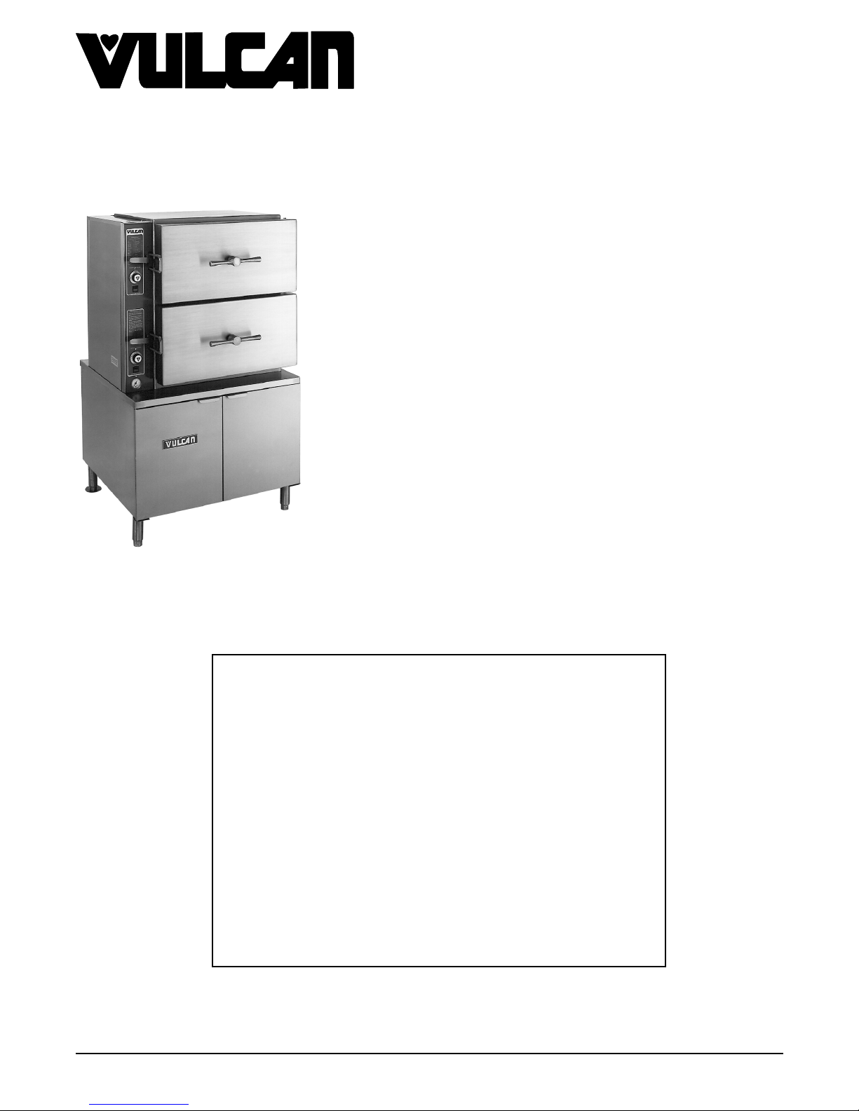
SERVICE MANUAL
VL BOILER BASE SERIES
CONVECTION STEAMERS
(GAS, ELECTRIC, DIRE CT AND REGENERATED)
VL2GPS ML-52391 VL2DPS ML-52749
VL2GMS ML-52388 VL2DMS ML-52750
VL2GAS ML-52390 VL2DAS ML-52751
VL2GSS ML-52389 VL2DSS ML-52752
VL3GPS ML-52395 VL3DPS ML-52753
VL3GMS ML-52392 VL3DMS ML-52754
VL3GAS ML-52394 VL3DAS ML-52755
VL3GSS ML-52393 VL3DSS ML-52756
VL2EPS ML-52741 VL2RPS ML-52757
VL2GPS SHOWN
This Manual is prepared for th e use of trained Vulcan Service
Technicians and should not be used by those not properly
qu alifi ed. If yo u have attend ed a Vulcan Service School for this
product, you may be qualified to perform all the procedures
described in this man ual.
This manual is not intended to be all encompassing. If you have
not attended a Vulcan Service School for this produc t, y ou should
read, in its entirety, th e repair procedure you wish to perform to
determine if you have the necessary tools, instruments a nd s k ills
required to perfo rm t he procedure. Procedures for which you do
not have th e n ecessary tools, instruments and skills should be
performed b y a t rained Vul can Service Technician.
VL2EMS ML-52742 VL2RMS ML-52758
VL2EAS ML-52743 VL2RAS ML-52759
VL2ESS ML-52744 VL2RSS ML-52760
VL3EPS ML-52745 VL3RPS ML-52761
VL3EMS ML-52746 VL3RMS ML-52762
VL3EAS ML-52747 VL3RAS ML-52763
VL3ESS ML-52748 VL3RSS ML-52764
- NOTICE -
Reproduction or other use of this Manual, without the express
written consent of Vulcan, is prohibited.
A product of VULCAN-HART LOUISVILLE , KY 40201-0696
Form 24650 (M ay 1999)

VL SERIES STEAMERS
g
g
g
g
g
g
g
g
g
g
g
g
g
g
g
g
TABLE OF CONTENTS
GENERAL............................................................................. 4
Introduction ........................................................................ 4
Compartment Pan Capacity ........................................................ 4
Model Desi
Water Conditi onin
Tools ............................................................................. 5
Specifications ...................................................................... 5
Water Supply ................................................................... 5
Steam Supply ................................................................... 5
Gas Steamers .................................................................. 6
Electric Steamers................................................................ 6
Steamer Operation .................................................................. 7
Gas Powered Steam Boiler ........................................................ 7
Electrically Powered Steam Boiler ................................................... 7
Re
enerated Steam Powered Boiler .................................................. 7
Direct Steam Powered Cooker ...................................................... 8
Boiler B lowdown and Steamer Shut off ................................................ 8
Cookin
Component Func tion ................................................................ 11
Cabinet Base Boiler Controls ...................................................... 11
Cookin
nations .............................................................. 4
.................................................................. 4
Compartment Control s ..................................................... 8
Compartment Control s .................................................... 13
REMOVAL AND REPLACEMENT OF PARTS ................................................ 14
Component Locat ions ............................................................... 14
Water Level Controls - Low Level Cut off and Differ ential .................................... 17
Water Level Gau
Cyclin
Boiler Assembly.................................................................... 18
Hi
Boiler Fill and Cold W ater Condenser Solenoid Valves ...................................... 19
Pilot and Thermocoupl e A ssembly (Gas Models) ........................................... 19
Gas Combinat ion Control Valve ........................................................ 19
Compartm ent Gasket and Door Screw Nut, Door and Bushin
Heater Contactor s .................................................................. 21
Heatin
Re
SERVICE PROCEDURES AND ADJUSTMENTS .............................................. 22
Boiler............................................................................ 22
Water Level Control(s) T est ........................................................... 24
Cyclin
Fill and Cold Wat er S olenoid Valves .................................................... 26
Compartment Pressure Adjustment ..................................................... 26
Hi
Boiler Not Fillin
Boiler B lowdown Drain Solenoid Valve .................................................. 27
Boiler Slow to Pressurize............................................................. 28
Inlet Water Strainer ................................................................. 29
Pilot and Thermocoupl e A ssembly (Gas Models) ........................................... 29
Gas Burners....................................................................... 31
Automatic I
Gas Manifold Pressure Adjustment ..................................................... 33
and High Limit Pressure Switches
(Gas and Electr ic Models) ........................................................ 17
h Limit Thermostat ............................................................... 18
Elements .................................................................. 21
enerated Steam Models (Steam Coil) ................................................ 21
Inspection..................................................................... 22
Clean-out (All Boiler Models) ...................................................... 22
Delimin
Descaler...................................................................... 23
and High Limit Pressure Switches
(Gas and Electr ic Models) ........................................................ 25
h Limit Thermostat ............................................................... 27
Air Shutter Adjustment ........................................................... 31
Inspection..................................................................... 31
e Assembly ......................................................... 17
s ............................... 20
Only (Models with Deliming Port Assembly).................................... 23
with Water ........................................................... 27
nition S y stems (Gas Models) ................................................ 31
Page 2 of 88

VL SERIES STEAMERS
g
g
g
g
g
g
g
g
g
g
g
g
g
g
g
g
g
Direct Steam Models ................................................................ 34
enerated Steam (Older Models) ..................................................... 34
Re
Heater Contactor s .................................................................. 34
Heatin
Elements .................................................................. 34
Thermal Switch - Prevent and Aut omatic M odels ........................................... 36
Water Level Gau
e Assembly ......................................................... 36
Steam Gate Valve(s) ................................................................ 37
ELECTRICAL OPERATION .............................................................. 38
Water Level Controls ................................................................ 38
Solid State - Low Level Cut-off & Differential Contr ol .................................... 38
Electro M ec hanical - Low Level Cut-off & Differential Control .............................. 40
Sequence of O per ation .............................................................. 42
Gas Models ................................................................... 42
Electric Models ................................................................. 45
Schematics, Gas Steam er s, B oiler Controls
VL2G AND VL3G - P r event, A utomati c , Standard and Manual ............................. 49
Manual I
Electronic I
Manual I
Electronic I
Wi ri n
Diagrams, Gas Steamers, Boiler Controls
nition, Standard Controls .............................................. 49
nition, Standard Controls ............................................ 50
nition, Csd-1 Code Controls ............................................ 51
nition, Csd-1 Code Controls .......................................... 52
VL2G AND VL3G - P r event, A utomati c , Standard and Manual ............................. 54
Manual I
Electronic I
Manual I
Electronic I
nition, Standard Controls .............................................. 54
nition, Standard Controls ............................................ 56
nition, Csd-1 Code Controls ............................................ 58
nition, Csd-1 Code Controls .......................................... 60
Schematics, Elect r ic Steam er s, B oiler Controls
VL2E AND VL3E - Prevent, A utomati c , Standard and Manual ............................. 62
Auto Blowdown, Standard Cont r ols .............................................. 62
Auto Blowdown, Cal-code Controls .............................................. 63
Wi ri n
Diagrams, El ec tric Steamers, Boiler Controls
VL2E AND VL3E - Prevent, A utomati c , Standard and Manual ............................. 64
Auto Blowdown, Standard Cont r ols (Contactor - 1 Std.) .............................. 64
Auto Blowdown, Standard Cont r ols (Contactors - 2 Std.) .............................. 66
Manual Blowdown, Cal-c ode Controls (Contactor s - 1 Std. 1 Aux. ) ...................... 68
Auto Blowdown, Cal-code Controls ( Contactor s - 1 Std. 1 Aux. ) ........................ 70
Auto Blowdown, Cal-code Controls (Contactor s - 2 Std. 2 Aux. ) ........................ 72
Manual Blowdown, Cal-c ode Controls (Contactor s - 2 Std. 2 Aux. ) ...................... 74
Wi ri n
Diagrams, El ec tric Heater Circuits
VL2E AND VL3E - Prevent, A utomati c , Standard and Manual ............................. 76
Schematic and Wirin
Diagrams, Dir ec t Steamers, Cabinet Base
VL2D AND VL3D - Prevent, Automati c , Standard and Manual ............................. 77
Wi ri n
Diagrams, Regenerated Steamers, Boiler Controls
VL2R AND VL3R - Prevent, Automati c , Standard and Manual ............................. 78
Schematic and Wirin
Diagrams - Compar tment Contr ols .................................... 80
Prevent ...................................................................... 80
Automatic..................................................................... 81
Standard ..................................................................... 82
Manual ....................................................................... 83
TROUBLESHOOTING .................................................................. 84
© VULCAN 1999
Page 3 of 88
VL SERIES STEAMERS - GENERAL
g
g
g
g
g
g
g
g
g
g
g
g
g
g
g
g
g
g
g
g
g
g
g
GENERAL
INTRODUCTION
Steam Cooking
e capacity pr essure steam er s offer an efficient
Lar
way to produce a wide v ar iety of foods in smal l
portions or lar
cook fresh foods, blanch foods for com plete cookin
later or will steam defrost and cook froz en foods.
Cookin
maximum c olor, f lavor and nutriti onal value with the
least expenditure of ener
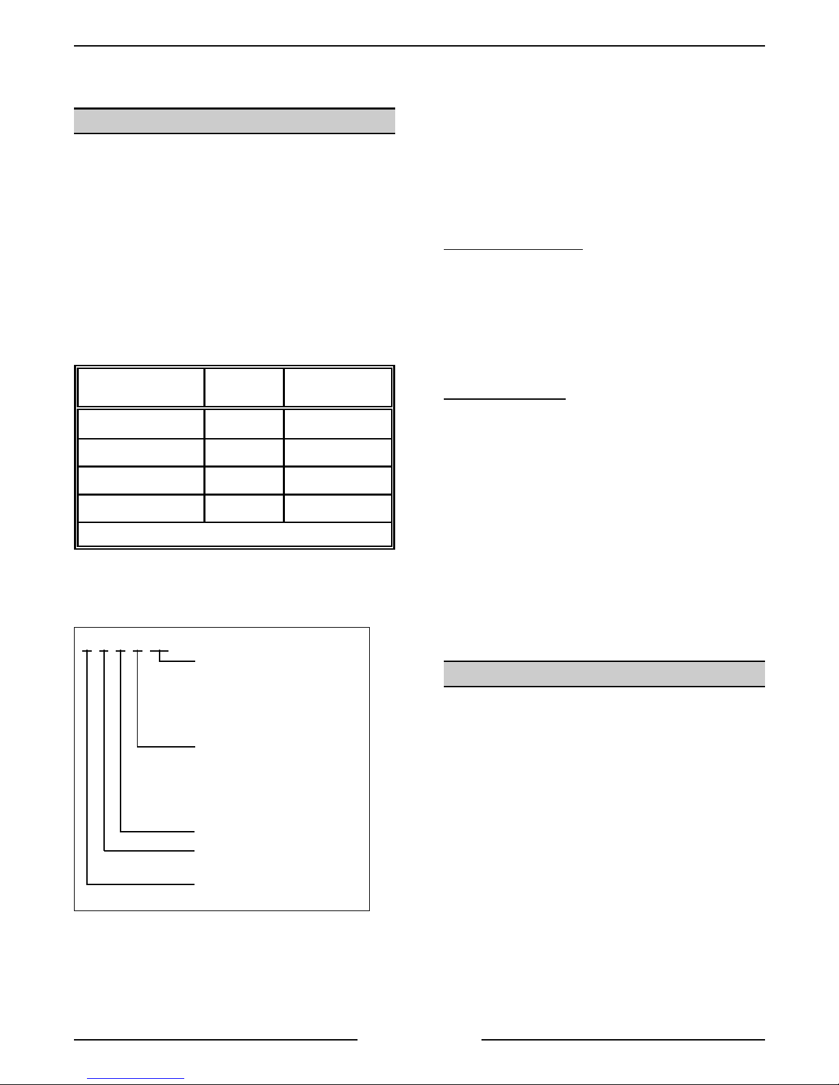
Compartment P an Capacity
PANS PER
COMPARTMENT
* Remove center support for 18x20 i nc h pans
er batches. Steamers can be used to
with steam assures the food will retain its
y and labor.
SIZE
4 12" x 20" 6.0
6 12" x 20" 4.0
8 12" x 20" 2.5
6 *18" x 20" 1.0
DEPTH
(INCHES)
Boiler Code Descriptions
Vulcan-Hart incorporates redundant controls in
compliance with Californi a Code ( Cal-Code) and
CSD-1 as an option on steam equipment when
required by state and/or local buildin
requirem ents. Descriptions of the codes are li sted
below.
Cal-Code Construction
electrical safet y c ircuits that, if tripped, must
manually be reset aft er the conditi on c ausi n
subsides. These controls consist of one dual
function water level cyclin
control and one sin
off control (A ux - LLCO) and a hi
switch in conjunc tion with a m ec hanical pressure
relief valve.
CSD-1 Constructi on
electrical safet y c ircuits that, if tripped, must
manually be reset aft er the conditi on c ausi n
subsides. These controls consist of one dual
function water level cyclin
control and one sin
off control (LLCO) and a hi
in conjunction with a m ec hanical pressure relief
valve. A dditional ly, both circuits have individual
indicator li
verifi c ation of the shutdown mode.
hts that will illuminate for a visual
- Redundant controls in the
and low level cut off
le function low water level cut-
- Redundant controls in the
and low level cut off
le function low water level cut-
h pressure relief switch
code
the trip
h pressure relief
the trip
Model Designations
L X X XX
V
Cooking Control Ty pes:
PS - Prevent Steam
AS - Automatic Steam
SS - Standard Steam
MS - Manual Steam
Heatin
G - Gas
E - Electric
D - Direct
R - Re
Number of Compartments
Lar
Steamer
Vulcan
System:
enerated
e Capacity Pr essure
Cal-Code and CSD-1 construc tion both requi r e
operator int er vention in the event of a shutdown.
CSD-1 is more informative by usin
to show which safety system was shutdown.
indicator lights
WATER CONDITIONING
Furnishing the boiler with soft water to reduc e scale
formation is important. Scale formation will reduce
steam output, cause premature component f ailure,
and shorten equipment life. Most water supplies
contain scale pr oduc in
and Ma
minerals remain and dissolve i nto the water. As the
concentration of these m inerals increases past a
certain point, they prec ipitate from the water and
coat the insi de of the boiler, heati n
thermostat bulbs and water lev el probes. Because of
the hi
precipitated mi ner als bake onto them and bec ome
very difficult t o rem ove.
nesium. As steam is generated, the
h temperat ur e of these surfaces, the
minerals such as Calcium
element s,
Page 4 of 88
VL SERIES STEAMERS - GENERAL
g
g
g
g
g
g
g
g
g
g
g
g
g
g
g
This causes several pr oblems:
1. Reduce the heat transfer effici enc y of the
heatin
syste m.
2. Cause premature failure of Electric heaters.
3. Water level probes will
ive false readings.
4. Thermostat bulbs will sense temperature
incorrectly.
These problems are common to any manufacturer's
steamer re
prevented by furnishin
ardless of design, but they can all be
the boiler with soft water.
Vulcan recommends the water contain less than
60ppm of “ total dissolved solids” (TDS) and hav e a
PH fact or between 7 to 8. These water properties
can be achieved by usin
a properly maintained
water softener.
Other chemical proper ties in water supplies can also
affect
ood steam generation and vary from within
each state and locality.
The water level probes in t he boiler use ions in t he
water to detect the water level. Do not use
fully
demineralized or de-ionized water since i t is "non
conductive" and the water level can not be detected.
NOTE: The use of strainers, or filters will not
remove mi ner als from the water.
Vulcan recommends that a local water treat ment
specialist be consulted before t he installat ion of any
steam
Steamers that operate over a lon
enerating equipment .
period of time
without the benefit of a water softener, whic h have
developed a heavy scale build up, shoul d be
cleaned bef or e usi n
a water softener.
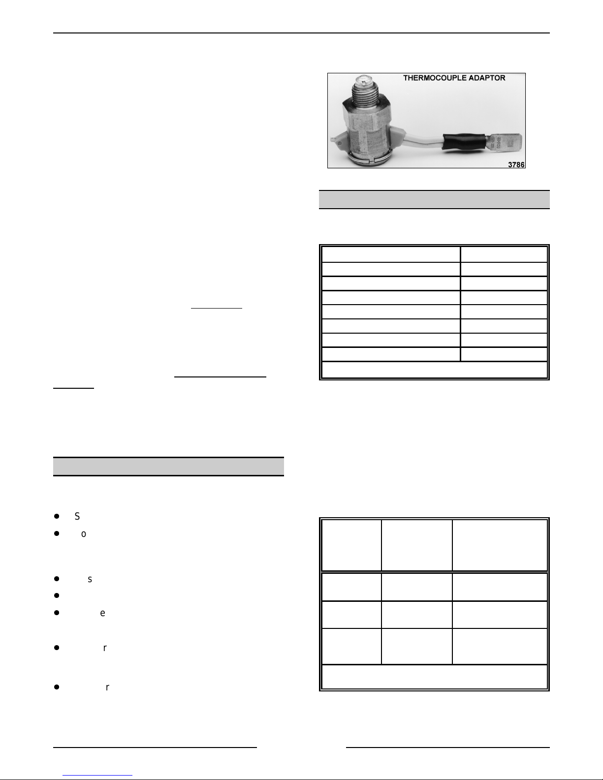
TOOLS
Standard
NOTE: A daptors vary between manufact ur er s. A n
example of one adaptor type is pictur ed below.
SPECIFICATIONS
Water Supply
Supply pressure should be 20-80 psi
In line str ainer for suppl y line (Not Supplied)
Supply connect ion cold
Total dissolved solids (TDS)* less than 60 ppm
Total alkalinity less than 20 ppm
Silica less than 13 ppm
Chloride less than 30 ppm
PH factor 7 to 8
(*17.1 ppm = 1
Steam Supply
Dry steam must be provided to the steam er for
suitable use. If the steam is heavy wit h c ondensate,
a Ball F loat Trap must be used in the li ne and
plumbed in before the pr essure reducin
ensure rapid heat up of heavy c old loads, the steam
supply line must be sized to maintain pr essure as
outlined below.
rain of har dness)
valv e. To
Standard set of hand tools.
Volt-Ohm-Meter (VOM) with AC current tester.
(Any quali ty VOM with a sensitivity of at least
20,000 ohms per volt can be used)
Gas leak checkin
Gas pressure manometer
Temperat ur e meter and thermocouple.
equipment .
Special
CLR Treatm ent Kit - Used to remov e
Calcium/Lime/Rust from a boiler ( Contact
Vulcan Author ized Service Centers ).
Adaptor to test thermocoupl e c losed circuit
es (DC) on gas models with m anual
volta
nition ( pur c hase l oc ally).
i
Page 5 of 88
DIRECT STEAM
STEAMERS
(POTABLE)
Supply
Pressure Input
Flow Rate 50 lb. per hour per
Pressure
Reducing Valve
Output
*Potable stea m is no t required for regene rated models but could
be used.
15 psi (min.) 15 psi (min.)
compartment
10 psi (furnished) set accordingly for good
REGENERATED
STEAMERS OLDER MODELS
(*NON-POTABLE)
125 lb. per hour
steam generation (1012psi)
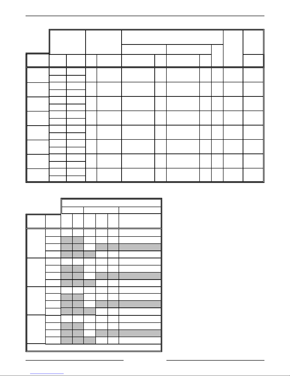
Gas Steamers
VL SERIES STEAMERS - GENERAL
INPUT
(BTU/HR)
MODEL NAT. PROP. NAT. PROP. RECOMMEND MIN RECOMMEND MIN
VL2GPS
VL2GMS
VL2GAS
VL2GSS
VL3GPS
VL3GMS
VL3GAS
VL3GSS
200,000 200,000
240,000 240,000
200,000 200,000
240,000 240,000
200,000 200,000
240,000 240,000
200,000 200,000
240,000 240,000
200,000 200,000
240,000 240,000
200,000 200,000
240,000 240,000
200,000 200,000
240,000 240,000
200,000 200,000
240,000 240,000
MANIFOLD
PRESSURE
(INCHES W.C.)
4.0 10.0 7.0 5.0 11.0 11.0 14.0 360 3.0
4.0 10.0 7.0 5.0 11.0 11.0 14.0 360 3.0
4.0 10.0 7.0 5.0 11.0 11.0 14.0 360 3.0
4.0 10.0 7.0 5.0 11.0 11.0 14.0 360 3.0
4.0 10.0 7.0 5.0 11.0 11.0 14.0 360 3.0
4.0 10.0 7.0 5.0 11.0 11.0 14.0 360 3.0
4.0 10.0 7.0 5.0 11.0 11.0 14.0 360 3.0
4.0 10.0 7.0 5.0 11.0 11.0 14.0 360 3.0
NATURAL PROPANE
LINE PRESSURE
(INCHES W.C.)
MAX
LOAD
(WATTS)
AMPS
(MAX)
120V
60HZ
Electric Steamers
MODEL
VL2EPS
VL2EMS
VL2ESS
VL2EAS
*std
TOTAL
KW
24* 116 100 67 58 29 34
36 100 87 44 50
42 117
48 116 58 67
24* 116 100 67 58 29 34
36 100 87 44 50
42 117
48 116 58 67
24* 116 100 67 58 29 34
36 100 87 44 50
42 117
48 116 58 67
24* 116 100 67 58 29 34
36 100 87 44 50
42 117
48 116 58 67
AMPERAGE
1 PHASE 3 PHASE 3 PHASE - 4 WIRE
208V 240V 208V 240V 480V 220/380V & 240/415V
Page 6 of 88

VL SERIES STEAMERS - GENERAL
g
g
g
gauge g
gauge g
gauge g
gaug
g
g
g
g
g
g
g
g
g
g
g
gaug
g
g
g
g
g
g
g
g
g
g
g
g
g
g
g
g
g
gaug
g
g
g
g
g
g
gauge g
gaug
g
gaug
g
g
gaug
g
g
g
g
STEAMER OPERATION
Ensure that all utility connections to the steamer
have been made and are turned on.
On model s that are CSD-1 equipped, amber colored
hts for hi pr essure and low water level will
li
illuminate and stay on until the boiler is full and the
manual reset switc h pr essed.
Gas Powered S t eam Boiler
5. Open the cabinet door and turn main power
switch ON. The red li
will be
solenoid valve will close. The boiler should fill,
in four to eleven minut es. Observe water l evel
that the l evel in the
full. Both valves on
be open to fill the
equipped with a m anual “ball” type blowdown
valve must be closed for the boiler to fill. The
cyclin
steam pressure in the boiler by cyclin
heatin
pressure.
A.
B.
in filling the boiler and the blowdown
lass to verify that water is in boiler and
pressure switch will m aintain the proper
system on and off to generate steam
On Models with Manual Ignition
knob on the
has three positions (On- P ilot-O ff) for
control of mai n bur ner s and pi lot. Turn
knob on
then depress and li
lit taper. Maint ain knob in depressed
position for about 30 seconds and release.
Observe that pilot burner flame stays on. If
the flame should
before reli
Turn knob on
valv e to ON. If the water level in the boiler
has reached the mi nimum level, burners
will i
the boiler . After appr oxim ately 15 minutes,
steam should be present for cookin
product. Observe that the boiler pressure
psi for models with a pressure re
valve or 4- 6 psi for models without the
valve.
On Models with Automatic Ignition
The knob on the
valve has two positions (On-Of f) f or
control of mai n bur ner s and pi lot. For the
automatic i
knob must be set in the ON position or
for the pilot and main burners will not flow.
as combination valve to PILOT
nite and begin to heat t he water in
e indicat es steam pressure of 9-11
ht will illuminate, water
lass is about half
lass a ssembly must
e. Older models
the
- The
as combination control valve
ht pilot burner with a
o out, wait 5 minutes
hting.
as combination control
ulatin
-
as combination control
nition system to work, the
as
Also, the i
ON/OFF/RESET swit ch must be in the ON
position to oper ate. This switch i s l oc ated
on the upper left side of the electrical
control box for t he i
A red li
is in the ON position. DO NOT ATTEMPT
TO MANUALLY LIGHT THE PILOT IN AN
AUTOMATIC TYPE IGNITION SYSTEM.
After the main power switch i s tur ned ON
and the i
switch is in the O N posi tion, sparkin
in three seconds later to light the
be
standin
sent back throu
indicat in
sparkin
boiler has reached t he minimum l evel, the
burners will i
water in the boiler. After approximately 15
minut es, steam should be present f or
cookin
pressure
pressure of 9-11 psi for models with a
pressure re
models without the valve. If a pilot flame
is not establi shed i mmedi ately, sparki n
will continue f or 90 seconds. After that
duration, the i
lock out and needs to be reset to start the
pilot and bur ner li
Electrically Powered St eam Boiler
Open the cabinet door and turn main power switch
ON. The red li
the boiler and the blowdown solenoid valve
fillin
will close. The boiler should fill, in approximately 11
minut es. Observe water l evel
that water is in boiler and that the level in the
lass is about half full. Both valves on gauge glass
assembly must be open to fill the
models equipped with a manual “ball” type
blowdown valve must be closed for the boiler to fill.
If t he water level in the boi ler has reached the
minimum level, the heater c ontactors will close, the
heaters will ener
the boiler . After appr oxim ately 15 minutes, steam
should be present for c ook in
the boiler pr essure
of 9-11 psi for models with a pressure re
valve or 4- 6 psi for models without the valve.
Regenerated St eam P owered Boiler
Open the cabinet door and turn main power switch
ON. The pilot li
the boiler and the blowdown solenoid valve
fillin
will close. Models equipped with a manual “ball
type” blowdown valve need to be closed for the
boiler to fill. The boiler should fill, in approximately
15 minut es.
nition c ontrol module
nition c ontrol module.
ht will illuminate when the switch
nition cont rol modules RESET
will
pilot. If the pilot lights, a signal is
h the ignition c able
the presence of pilot flame and
stops. If the water level in the
nite and begin to heat t he
product. Observe that the boiler
e indicat es a steam
ulating valve or 4- 6 psi for
nition c ontrol module will
hting cycle again.
ht will illuminate, water will begin
lass to verif y
e. Older
ize and begin to heat t he water in
product. Observe that
e indicat es steam pressure
ulatin
ht will illuminate, water will begin
e
Page 7 of 88

VL SERIES STEAMERS - GENERAL
gauge g
gauge g
gauge g
gaug
g
g
g
g
g
g
gaug
g
g
g
g
g
g
g
g
g
g
g
g
g
g
g
g
g
g
g
g
g
g
g
g
g
Observe water level
is in boiler and that the level in the
lass to verify that water
lass is
about half full.
Both valves on the
open to fill the
e. When the water reaches the
lass a ssembly must be
minimum level, the steam sol enoid valve will open,
allowin
exchan
steam to enter the steam coil in the heat
er tank and begin heating the water. After
approximately 20 minutes, a suffic ient amount of
pressurized steam should be present for cooki n
product.
Direct Steam Powered Cooker
1. Open the cabinet door and turn main power
switch ON.
A. The red li
ht on the switch will illuminate.
B. If steam pr essure is above the m inimum
settin
on the cooking compartment
pressure switch then the switch will close,
ready li
ht will come ON and power to the
other controls will be supplied.
C. Observ e that the steam pr essure
e in
the cabinet base, indicates 10-12 psi.
2. Steamer is ready to cook product .
Boiler Blowdown and Steamer Shut off
Turn the steam er off at least once daily and blow
down the boiler to r emov e sedi ments, scalants and
lime build-up in the boiler . Always blowdown the
boiler when it is under maximum pr essure and no
steam is bein
used.
3. Automatic blowdown.
A. Newer Models
- Open the cabi net door
and turn main power switch OFF. The
switches’ red li
ht will go out, the
blowdown/drain solenoid valve will be de-
ized and the boi ler will begin to
ener
drain. The c old water condenser solenoid
will continue to operat e, as needed, to
condense steam and to cool the water
oing into the drain.
B. Older Models
- Turn power switch OFF
and depress blowdown timer button.
Blowdown timer will operate for 4 minutes.
At the end of blowdown, turn fill switch ON
and allow boil er to fill.
4. Manual blowdown.
A. A ll Models
- Turn power switch OFF. Open
blowdown valve located on the bottom
front of the cabi net base. After the boiler
has completely drained, c lose blowdown
valve and t ur n fill switch to ON and allow
boiler to fill.
Cooking Compartment Controls
Close the compar tment door and t ur n the screw
handle clock wise
until the gasket touches the
compartment surfac e then ½ turn f ur ther to
adequately seal t he c ompartm ent. If steam leaks
occur after compart ment heat up and pressurization,
turn handle clockwise
again to inc r ease the seal in
force unt il the l eak stops.
Proceed to the cook in
compartment control
instructions that apply to the steamer in use.
1. Manual
A. S et the manual timer to the desired
cookin
tim e. If preheating is desired,
allow five to ten mi nutes (recomm ended)
of additional time at t he be
cook cycle. The len
th of time will v ary
inning of the
with the type, si z e, temperat ur e and
conditi on ( frozen or thawed) of the product
and must be determined f r om experience.
Pull t he steam control ar m handle forward
and lock it by pullin
This closes the steam exhaust
and opens the steam inlet
allowin
Durin
steam to enter the compartment.
preheat, cool er air and condensate
the handle down.
ate v alve
ate v alve,
are exhausted from the compartm ent
h the steam tr ap ( c ondenser) until
throu
the temper ature reaches 180°F, closin
the internal bellows. Throughout the
cookin
cycle, the compartment pressure
should be 6 psi if equipped with a
compartment pressure re
ulating valve.
On model s without the compartment
pressure re
ulating valv e, the
compartment pressure cycles with the
boiler pressure between 4 and 6 psi.
B. When the timer bell rin
s to signal the end
of a cook cycle, turn it OFF. Lift the steam
control arm handle to unlatch team c ontrol
arm. An internal sprin
will automatically
pull the ar m to the rear. This closes the
steam inlet
steam exhaust
ate v alve and opens the
ate v alve, allowing steam
and pressure to exit the compartment.
C. W ait approximately 30 seconds for the
steam to exhaust from the compartment
and to depressurize. Tur n the screw
handle on the compartment door
countercloc k wise
er seals against the compartment
lon
surface. After the remainin
until the gasket no
steam
escapes, move the latch paddle to the left
and open the door.
Page 8 of 88

VL SERIES STEAMERS - GENERAL
g
g
g
g
g
g
g
g
g
g
g
g
g
g
g
g
g
g
g
g
g
g
g
g
g
g
g
g
g
g
g
g
g
g
g
g
g
g
g
g
g
g
g
g
g
g
g
g
g
g
g
2. Standard
A. S et the timer to the desired c ook in
The timer must be set past five minutes to
e the state of the tim er c ontrol micro
chan
switch contacts. I f preheati n
is desired,
allow five to ten mi nutes (recomm ended)
of additional time at t he be
cook cycle. The len
th of time will v ary
inning of the
with the type, si z e, temperat ur e and
conditi on ( frozen or thawed) of the product
and must be determined f r om experience.
B. P ull the steam control arm handle forward
and lock it by pullin
the handle down.
This closes the steam exhaust
and opens the steam inlet
allowin
steam to enter the compartment.
ate v alve,
C. Press the compart ment power switch to
ize the timer and red light. The
ener
balance of the cookin
automatic. Durin
sequence is
preheat, cool er air and
condensate are exhausted from the
compartment throu
h the steam tr ap
(condenser) until the temper ature reaches
180°F, closin
Throu
hout the cooki ng cycle, the
the internal bellows.
compartment pressure should be 6 psi if
equipped with a compartment pr essure
ulating valve. On models without the
re
compartment pressure re
ulating valve,
the compartment pressure cycles with the
boiler pressure between 4 and 6 psi.
D. Approximatel y one minute before timer
reaches zero the steam c ontrol solenoid is
ized to unl atch the steam control
ener
arm. An internal sprin
will automatically
pull the ar m to the rear. This closes the
steam inlet
steam exhaust
ate v alve and opens the
ate v alve, allowing steam
and pressure to exit the compartment.
When the tim er r eac hes "0" the red li
shuts off and a buz z er sounds indicatin
the end of the cook cycle. Turn the
compartment power swi tch OFF to silence
the buzzer and remove power from the
compartment controls.
E. Turn the screw handle on the
compartment door counter c lockwise
asket no longer seals against the
the
compartment surfac e. After the remainin
steam escapes, move the l atch paddle to
the left and open the door.
time.
ate v alve
ht
until
3. Automatic
A. S et the timer to the desired c ook in
The timer must be set past five minutes to
e the state of the tim er c ontrol
chan
micro switch contacts.
B. P ull the steam control arm handle forward
and lock it by pullin
the handle down.
This closes the steam exhaust
and opens the steam inlet
allowin
steam to enter the compartment.
ate v alve,
C. Press the compart ment power switch to
supply power to the com par tment cont r ols.
The automatic com par tment cont r ols,
feature load compensated cookin
utilizin
a thermal switch. With this
feature, when the compartment
temperat ur e r eac hes 180°F (the
temperat ur e at which preheatin
defrosti n
is compl ete) the red light will
then come on and t he timer will start. For
a small food load, the delay ti me before
the timer starts mi
For a lar
e food load, the delay time coul d
ht be a mi nute or less.
be four to five minutes. Durin
cooler air and c ondensate ar e exhausted
from the compartment thr ou
h the steam
trap (condenser) until the temperature
reaches 180°F, closin
bellows. Throu
hout the cooki ng cycle, the
the internal
compartment pressure should be 6 psi if
equipped with a compartment pr essure
ulating valve. On models without the
re
compartment pressure re
ulating valve,
the compartment pressure cycles with the
boiler pressure between 4 to 6 psi.
D. Approximatel y one minute before timer
reaches zero the steam c ontrol solenoid is
ized to unl atch the steam control
ener
arm. An internal sprin
will automatically
pull the ar m to the rear. This closes the
steam inlet
steam exhaust
ate v alve and opens the
ate v alve, allowing steam
and pressure to exit the compartment.
When the tim er r eac hes "0" the red li
shuts off and a buz z er sounds indicatin
the end of the cook cycle. Turn the
compartment power swi tch OFF to silence
the buzzer and remove power from the
compartment controls.
E. Turn the screw handle on the
compartment door counter c lockwise
asket no longer seals against the
the
compartment surfac e. After the remainin
steam escapes, move the l atch paddle to
the left and open the door.
time.
ate v alve
time by
or
preheat,
ht
until
Page 9 of 88

VL SERIES STEAMERS - GENERAL
g
g
g
g
g
g
g
g
g
g
g
g
g
g
g
g
g
g
g
g
g
4. Prevent
A. S et the timer to the desired c ook in
The timer must be set past five minutes to
e the state of the tim er c ontrol
chan
micro switch contacts.
B. P ull the steam control arm handle forward
and lock it by pullin
This opens the steam inlet
allowin
steam to enter the compartment.
the handle down.
ate v alve,
C. Press the compart ment power switch to
supply power to the com par tment cont r ols.
The prevent compartment cont r ols feature
load compensated c ook times by utilizin
a thermal switch. With this feature, when
the compartment temperature reaches
180°F (the t emperature at whic h
preheatin
red li
or defrosting is complete) the
ht will come on and the t imer wil l
start. For a small food load, the delay time
before the timer star ts mi
or less. For a lar
e food load, the delay
ht be a mi nute
tim e c ould be four and five mi nutes.
Durin
preheat, the steam exhaust
solenoid valve (N.O.) is open to allow the
full free venti n
of cool er air and
condensate from the compar tment. When
the temper ature reaches 180°F, t he
exhaust solenoid valve is ener
closes. The com par tment should t hen
pressurize to 6 psi.
time.
ized and
D. Approximatel y one minute before timer
reaches zero the steam c ontrol solenoid is
ized to unl atch the steam control
ener
arm. An internal sprin
will automatically
pull the ar m to the rear. This closes the
steam inlet
steam exhaust
ate v alve and opens the
ate v alve, allowing steam
and pressure to exit the compartment.
When the tim er r eac hes "0" the red li
shuts off and a buz z er sounds indicatin
the end of the cook cycle. Turn the
compartment power swi tch OFF to silence
the buzzer and remove power from the
compartment controls.
E. Turn the screw handle on the
compartment door counter c lockwise
asket no longer seals against the
the
until
compartment surfac e. After the remainin
steam escapes, move the l atch paddle to
the left and open the door.
ht
Page 10 of 88

COMPONE NT FUNCTION
g
g
g
g
g
g
g
g
g
g
g
g
g
g
g
g
g
g
g
g
g
g
g
g
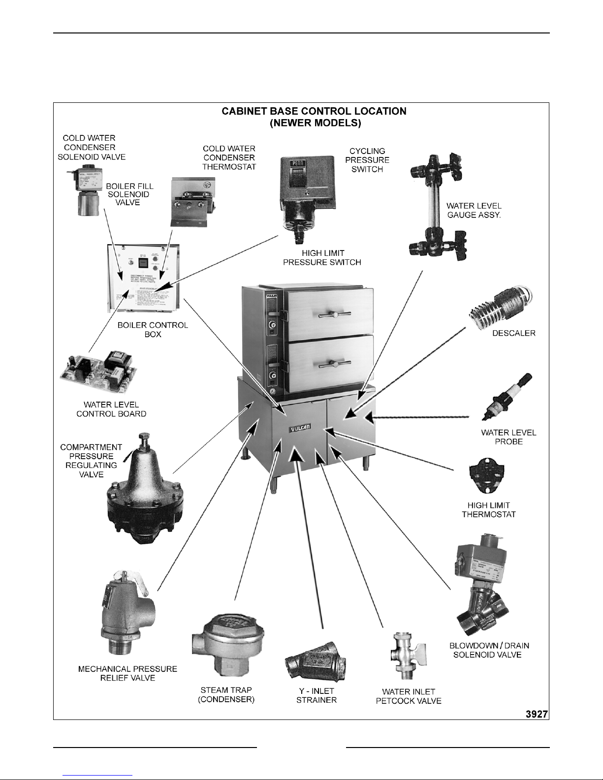
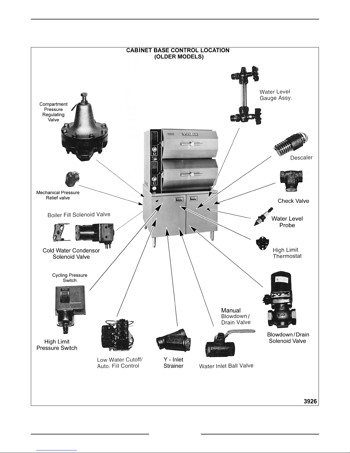
CABINET BASE BOILER CONTROLS
Water Level
Gauge Assembly ...............
Water Level Cont rol and
Level Sensing Probes ...........
VL SERIES STEAMERS - GENERAL
Permi ts a visual c onfirmation the water level is bein
boiler durin
ht of t he glass. The manual valves at t he top and bottom of this
hei
assembly must be full y open and only closed if the
dama
These controls allow water to enter the boiler to fill and maintain the
proper water level. T hey will also shut off the heat source to the boiler if
the water level drops too l ow. T he water level control works by usin
three different pr obe lengths to moni tor the water level. The probes
consist of a hi
operation. The correct water l evel is a point one-half of the
ed.
h level (HL), low level (LL) and low water cut-off (LLCO ) .
maint ained in
lass tube is
Boiler Fill Solenoid Valve ........
Cold Water Condenser
Solenoid Valve .................
Cycling Pressure Switch .........
High Limit Pressure Switch ......
Blowdown/Drain
Solenoid Valve .................
Inlet Water Strainer .............
Admits water to the boiler when dem anded by the water level control to
maintain the correct water level in the boiler.
Allows cold water flow into the boiler blowdown drain box to condense
steam and cool the hot water before its dischar
Controls boiler pressure between prescribed limits by tur nin
source on and off.
A switch of identical desi
h limit. T he pr essure settings are at higher and lower limits than t he
hi
cyclin
boiler pressure reaches its limit and autom atically resets after the
pressure drops below the lower limit set point.
This valve is plumbed into the drai n line of the boiler. Newer steamer
models will automatically blowdown when power is turned off by usi n
normally open solenoid valve. Older models can have a solenoid valve
that is activated by depressin
have a manual “ball” type valve.
A strainer i s used in t he water inlet l ine to prevent for ei
becomin
to keep unwanted partic les out of the system. A "Y" str ainer should be
inserted upstream of the fill solenoid valve. On models usin
steam supply, a str ainer is also used in the pressure re
pressure switch in order to tur n off the heat source before the
lodged in the fill or cold water condenser solenoid valves and
n to the cycling pressure switch but used as a
a separate blowdown timer button or
e into the drain.
the heat
n matter from
a direct
ulating valve.
a
Power Switch..................
Water Inlet Valve ...............
High Limit Thermostat ..........
Descaler ......................
When turned ON, power is supplied to the control s and the steam
enerating process is started in the boiler. The power switch is located
on the front of the boiler control box.
The water inlet valve is used to stop water flow to the steamer when the
steamer is bei n
valve while older models will be a “ball” type valve. This valve should
remain open dur in
A protective device that shuts off the heat source if the boiler
temperat ur e exceeds a specified limit. A ll standard m odels are equipped
with a surface hi
s submerged in water inside t he boiler and is used to hel p c ontrol
Han
boiler surface scalin
Page 11 of 88
servi c ed. Newer models will have a small Petcock type
normal oper ation.
h limit.
. Two descalers are used in each boiler.

VL SERIES STEAMERS - GENERAL
g
g
g
g
g
g
g
g
g
g
g
g
g
g
g
g
g
g
g
g
g
g
g
g
Handhole Cover Assembly ....... When unbolted and removed, allows internal examination and cleanin
of boiler shell and i ts components if required.
Boiler Pressu re Gauge .......... Indicates the amount of steam pressure in the boiler.
Check Valve ................... On models with the delime pipin
of hot water and steam out of the delime funnel if the manual delime fill
valve were to be opened.
Delime Port Assembl y ........... O n models with the delime pipin
other inter nal components to be delimed, easily removin
and rust build up.
Gas Pilot ..................... Shoul d always remain lit to li
ht the main burners upon a call for heat
unless the steamer will not be in use for an extended period. If the pilot
flame
oes out, wait 5 minutes before relighting.
Gas Burners................... Heats the water in the boiler to
Gas Combination Control Valve . . . A
as solenoid v alve that opens to allow gas flow when a call for heat is
made. Also re
ulates the m anifol d gas pressure and supplies the gas
pilot.
Transformer ................... Provides 24VAC power to i
electronic i
nition)
Ignition Control Module ......... Controls and monit or s
nition c ontrol module. (gas models with
as heating. Energizes pilot valve coil to supply
as to pilot, generates spark to ignite gas at the pilot, moni tors the
presence of flame and ener
supply
the
as to the mai n bur ner s. The pilot and main solenoi ds are part of
as combination control valve. (gas models with elec tronic ignition)
izes mai n valve coi l upon a call for heat to
Ignition Control Module
Reset (ON/OFF) Switch .......... Controls power to the i
module if the
nition)
i
as ignition exceeds trial tim e. (gas models with elec tronic
nition c ontrol module and allows a reset of the
assembly opti on, prevents the ejecti on
assembly opti on, allows the boil er and
calcium, lime
enerate steam.
Heater Contacto r
(Electric Bo ilers) ............... When coil is ener
ized, supplies power to the electric heating element s.
Heating Elements
(Electric Bo ilers) ............... Heats the water in the boil er to
enerate steam.
Steam Header Assembly ......... Main steam supply line fr om the boiler to the steam header inlet i n the
cookin
control compartm ent.
Pressure Relief V alve ........... A m ec hanical device that opens to relieve steam pr essure in the boiler if
the pressure exceeds 15 psi.
Compartment P ressure
Regulating Valve ............... Reduces steam pressure form t he boiler or bui ldin
enerated models) to supply the compartment s a steam pressure of 6
re
steam (dir ec t and
psi. Standard on PS , option on MS, S S and A S c ompartm ent controls.
Page 12 of 88

VL SERIES STEAMERS - GENERAL
g
g
g
g
g
g
g
g
g
g
g
g
g
g
g
g
g
g
g
g
g
g
g
g
g
g
g
g
g
g
g
COOKING COMPARTMENT CONTROLS
The top half of t he steamer consists of two to three separate cooking compartments depending on the model .
Each compartment functions independently with i ts own set of controls. Power i s supplied to the controls throu
the compartment power switch and the cook in
models have a load compensatin
thermal switch that prevents the contr ols from r ec eiving power until the
compartment reaches 180°F to close the switch.
tim er c ontrol micro switch contacts. Prev ent and Automat ic
h
Compartment Power Switch......
Cooking Light (Red) ............
Cooking Timer .................
Buzzer .......................
Steam Exhaust S olenoid Valve . . .
Steam Header Inlet (manifold) ....
Compartment P ressure Gauge ....
Steam Contro l Arm Solenoid .....
Supplies power to the cook in
When lit, indicates steam er is in a cookin
compartment controls.
cycle. (All models except
manual)
Use to set desired cookin
cycle time between 0-60 minutes. Energizes
the buzzer when time expir es (All models except manual). On P r event
models, also de-ener
before the end of a cook cycle to allow compartment venti n
nals end of a cook cycle, must be turned of f manual ly. (All models
Si
izes the steam exhaust solenoid valve one minute
.
except manual)
A normal ly open v alve that allows full com par tment ventin
condensate up to 180°F durin
vent in
” after energized by the closing of the t her mal switch. The valve
compartment heat up and “limited free
of air and
remains closed to allow compar tment pressurization to 6 psi until one
minute before the end of a cook cycle at which point t he timer control
micro switch contacts (SW2) chan
e state and de-energize the valve to
vent the compartment of pr essure and steam . (prev ent models)
Main steam suppl y line f r om the boiler for each c ook in
Supplies steam to the manual steam
ate v alves.
Indicates the amount of steam pressure in cookin
When ener
control arm off of t he c atch, all owin
closes the steam i nlet
ized, engages the lift arm ( plunger) to raise the steam
it to return to its rear position. This
ate v alve and opens the steam exhaust gate
compartment.
compartments.
valve. ( pr event, automati c and standar d models)
Thermal S witch
(Load Compensator) ............
Steam Gate Valves .............
Steam Trap ( Condenser) .........
Controls power to the preheat cycle components. Turns the cookin
on, ener
cookin
izes the steam exhaust solenoid valve and energizes the
timer motor to start timing, aft er the compartment reaches
light
180(F. (prevent and automatic models)
Manual valves actuated by the steam control ar m. Allows steam to flow
into the cook in
the arm is in a forward position and exhaust the steam throu
exhaust steam
use a steam exhaust solenoid valve t o exhaust the steam and a si n
steam
ate v alve as the steam inlet. The automatic, standar d and
manual models use one steam
one additional steam
Exhausts air and condensate from c ompartm ent durin
compartment through the inlet steam gate v alve when
h the
ate v alve when the arm is at the rear . Prev ent models
le
ate v alve to exhaust the steam and
ate v alve as the steam inlet.
preheat until the
compartment temperature reaches approx imately 180(F. The bel lows
then close, stoppi n
the exhaust. ( all models except prevent)
Page 13 of 88
VL SERIES STEAMERS - REMOVAL AND REPLACEMENT OF PARTS
REMOVAL AND REPLACEMENT OF PARTS
COMPONENT LOCATIONS
Page 14 of 88
VL SERIES STEAMERS - REMOVAL AND REPLACEMENT OF PARTS
Page 15 of 88

VL SERIES STEAMERS - REMOVAL AND REPLACEMENT OF PARTS
g
g
g
COOKING COMPARTMENT CONTROLS - COMPONENT CONFIGURATIONS
1. Prevent
(shown above)
thermal switch, inlet steam
valve, steam control ar m solenoid, timer, buzzer and power switch
with li
ht. Does not use a steam tr ap.
2. Autom atic same as prevent except does not
valve but does
include an exhaust steam gate v alve and two steam
ate v alve, steam exhaust sol enoid
include steam exhaust solenoi d
traps.
3. Standard same as automatic except does not include thermal switch.
4. Manual manual and exhaust steam
ate v alves and a manual timer.
Includes two steam t r aps.
Page 16 of 88

VL SERIES STEAMERS - REMOVAL AND REPLACEMENT OF PARTS
g
g
g
gaug
g
g
g
g
g
g
gauge g
g
g
g
g
g
g
g
g
WATER LEVEL CONTROLS -
LOW LEVEL CUT OFF AND
DIFFERENTIAL
WARNING:
POWER TO T HE MACHINE AT THE MAIN
CIRCUIT BO X. P LA CE A TAG ON THE CIRCUIT
BOX INDICATING THE CIRCUIT IS BEING
SERVICED.
Solid State
1. Open the cabinet base doors.
2. Remove the two screws at the top of the boiler
3. Water level control is mounted on the back
4. Disconnect lead wir es from the boar d and
5. Reverse procedur e to install and c hec k for
Electro Mech anical
DISCONNECT THE ELECTRICAL
control box and allow cover to drop down.
side of cover.
remove the water level control.
proper operation.
4. Slide t he
the tube is cl ear of the fittin
5. When r einstallin
washers. Do not over tighten the packi ng nuts;
it coul d br eak the
6. Open the top and bottom valves and check for
proper operation.
lass tube upwards until the bot tom of
and lift it out.
the tube use new sealin
lass.
CYCLING AND HIGH LIMIT
PRESSURE SWITCHES
(GAS AND ELECTRIC MODELS)
WARNING:
POWER TO T HE MACHINE AT THE MAIN
CIRCUIT BO X. P LA CE A TAG ON THE CIRCUIT
BOX INDICATING THE CIRCUIT IS BEING
SERVICED.
1. Open the cabinet base doors and remov e the
left side panel.
2. Remove the two screws at the top of the boiler
control box and allow cover to drop down.
DISCONNECT THE ELECTRICAL
1. Open the cabinet base doors.
2. Remove the two screws from t he left and r i
side of the water level control box and lift cover
off.
3. Disconnect lead wir es from the c ontrol bein
replaced and remove.
4. Reverse procedur e to install and c hec k for
proper operation.
ht
WATER LEVEL GAUGE
ASSEMBLY
WARNING:
POWER TO T HE MACHINE AT THE MAIN
CIRCUIT BO X. P LA CE A TAG ON THE CIRCUIT
BOX INDICATING THE CIRCUIT IS BEING
SERVICED.
1. Open the cabinet base doors and remov e the
2. Close the valve at the top and at the bottom of
3. Unscrew the packin
DISCONNECT THE ELECTRICAL
ht side panel.
ri
the
of the
e assembly.
nuts at the top and bottom
lass tube.
3. The pressure switches are located at the rear of
the box. The pressure switch on the ri
cyclin
the hi
switches, dif ferin
4. Remove the cover from the pressure switch
bein
5. Disconnect the pressure fittin
of the switch.
6. Remove the mount in
of the control box and lif t out the pressure
switch.
7. Preset the new pressure switch to the
approximate cut-out (off) and cut-i n ( on) set
points before installin
chart under “CYCLI NG AND HIGH LIMIT
PRESSURE SWITCHES (GAS AND
ELECTRIC MODELS)” in “SERVICE
PROCEDURES AND ADJUSTMENTS”.
8. Reverse procedur e to install .
9. Adjust the pressure switch(s) final set poi nts as
outlined under “ CY CLING AND HIGH LI M IT
PRESSURE SWITCHES (GAS AND
ELECTRIC MODELS)” in “SERVICE
PROCEDURES AND ADJUSTMENTS” and
check for pr oper oper ation.
or prim ar y c ontrol; the one on the left is
h limit contr ol. They are identical
only in t heir settings.
replaced and disconnect the lead wires.
s at the bottom
screws on the back side
. See the boiler pressure
ht is the
Page 17 of 88

VL SERIES STEAMERS - REMOVAL AND REPLACEMENT OF PARTS
g
g
g
g
g
g
g
g
g
g
g
g
g
BOILER ASSEMBLY
WARNING:
POWER TO T HE MACHINE AT THE MAIN
CIRCUIT BO X. P LA CE A TAG ON THE CIRCUIT
BOX INDICATING THE CIRCUIT IS BEING
SERVICED.
WARNING:
SERVICING THE UNIT.
WARNING:
DURING SERVI CING MUST BE CHE CK E D FOR
LEAKS. CHECK WITH A SOAP AND WATER
SOLUTION (BUBBLES). DO NOT USE AN OPEN
FLAME.
1. Blow down the boiler and allow to cool, if
2. Ensure that all utilities to the steamer are off
3. Disconnect the steam supply li ne, power leads
4. Disconnect all plumbin
5. Disconnect the remainin
6. Remove the screws holdin
7. Remove the anchor screws holdin
DISCONNECT THE ELECTRICAL
SHUT OFF THE GAS BEFORE
ALL GAS JOINTS DISTURBED
necessary.
and disconnected. Drain any excess water fr om
the boiler .
and drain lines from the cookin
top to the boi ler base.
connections and power
leads from the components inside the control
boxes that would obstruct the removal of the
boiler throu
remove those control boxes.
electrical connections from the boiler t o the
controls.
collector to the base.
the frame. Slide the boil er forward. The burner
box, anchored only by the boiler, must be
prevented from slidin
h the front of the base, t hen
forward with the boiler.
compartment
plumbing and
the flue and flue
the boiler to
HIGH LIMIT THERMOSTAT
WARNING:
POWER TO T HE MACHINE AT THE MAIN
CIRCUIT BO X. P LA CE A TAG ON THE CIRCUIT
BOX INDICATING THE CIRCUIT IS BEING
SERVICED.
1. Open the cabinet base doors.
2. Electric model s onl y - for
to step 3.
A. Newer Models
B. Older Models
3. Gas Models only.
A. Remov e the thermostat c over which is
4. Reverse procedur e to install and c hec k for
proper operation.
DISCONNECT THE ELECTRICAL
as models proceed
- are not equipped wit h a hi
limit thermostat but rely on the Hi l imit
pressure switch instead.
- the high limit thermostat is
located behi nd the contactor box cov er .
On electr ic boiler s with two heatin
element s, the thermostat is connected to
one of the heat in
electric boilers with four heati n
the therm ostat is located on an aluminum
plate between the cent er pair of elements
at the top of the elements. Remove the
thermostat lead wires and mounti n
replace thermostat and check for proper
operation.
located on the front of the boil er .
Disconnect the t her mostat lead wires and
remove the nuts securin
thermostat to the boiler surface.
element lugs. On
element s,
nuts,
the high limit
8. Reverse procedur e to install a new boiler and
check for leaks and proper operation.
Page 18 of 88

VL SERIES STEAMERS - REMOVAL AND REPLACEMENT OF PARTS
g
g
g
g
g
g
g
g
g
BOILER FILL AND COLD WATER
CONDENSER SOLENOID VALVES
WARNING:
POWER TO T HE MACHINE AT THE MAIN
CIRCUIT BO X. P LA CE A TAG ON THE CIRCUIT
BOX INDICATING THE CIRCUIT IS BEING
SERVICED.
1. Turn off the water supply t o the steamer.
2. Open the cabinet base doors and remov e the
3. Disconnect the power lead wir es from the
4. Disconnect the water lines for t he valve bein
5. Reverse procedur e to install .
DISCONNECT THE ELECTRICAL
two screws at the top of the boiler control box
and allow cover to drop down. Both solenoid
valves are l oc ated side by side near the front of
the boiler control box with the boiler fill on the
ht and the cold water c ondenser t o the left.
ri
solenoid valve bein
servi c ed and r emov e the valve.
servi c ed.
PILOT AND THERMOCOUPLE
ASSEMBLY ( GAS MODELS)
WARNING:
POWER TO T HE MACHINE AT THE MAIN
CIRCUIT BO X. P LA CE A TAG ON THE CIRCUIT
BOX INDICATING THE CIRCUIT IS BEING
SERVICED.
WARNING:
SERVICING THE UNIT.
WARNING:
DURING SERVI CING MUST BE CHE CK E D FOR
LEAKS. CHECK WITH A SOAP AND WATER
SOLUTION (BUBBLES). DO NOT USE AN OPEN
FLAME.
DISCONNECT THE ELECTRICAL
SHUT OFF THE GAS BEFORE
ALL GAS JOINTS DISTURBED
GAS COMBINATION CONTROL
VALVE
WARNING:
POWER TO T HE MACHINE AT THE MAIN
CIRCUIT BO X. P LA CE A TAG ON THE CIRCUIT
BOX INDICATING THE CIRCUIT IS BEING
SERVICED.
WARNING:
BEFORE SERVICING THE UNIT.
WARNING:
DURING SERVI CING MUST BE CHE CK E D FOR
LEAKS. CHECK WITH A SOAP AND WATER
SOLUTION (BUBBLES). DO NOT USE AN OPEN
FLAME.
NOTE:
servi c eable and should not be disassembled. Once
the problem has been isolated to this control,
replace it. Do not attempt to repair the assembly.
1. Open the cabinet base doors and remov e the
two screws at the top of the boiler control box
and allow cover to drop down.
2. Disconnect elec trical suppl y wir es and conduit
runnin
3. Disconnect the t her mocouple l ead ( if
applicable), pil ot
and pipe connections on each side of the
control.
4. Reverse procedur e to install .
5. Set manifold pr essure as outlined under “GAS
MANIFOLD PRESSURE ADJUSTMENT” in
“SERVICE PROCEDURES AND
ADJUSTMENTS”.
6. Check for pr oper oper ation.
DISCONNECT THE ELECTRICAL
SHUT OFF THE GAS SUPPLY
ALL GAS JOINTS DISTURBED
Gas combination control valves are not
to the com bination cont r ol valve.
as supply tube from control
1. Open the cabinet doors to access the pilot and
thermocouple assembly. T he assembly is
located to the ri
half way back from the front.
2. Disconnect thermocouple and pi lot
from the combination contr ol valve.
tubin
3. Remove the two screws holdin
bracket.
4. Replace the ther mocouple or pilot assembly
and check for pr oper oper ation.
ht of t he c enter burner and
as supply
the pilot to its
Page 19 of 88
VL SERIES STEAMERS - REMOVAL AND REPLACEMENT OF PARTS
g
g
g
g
g
g
g
g
g
g
g
g
g
g
g
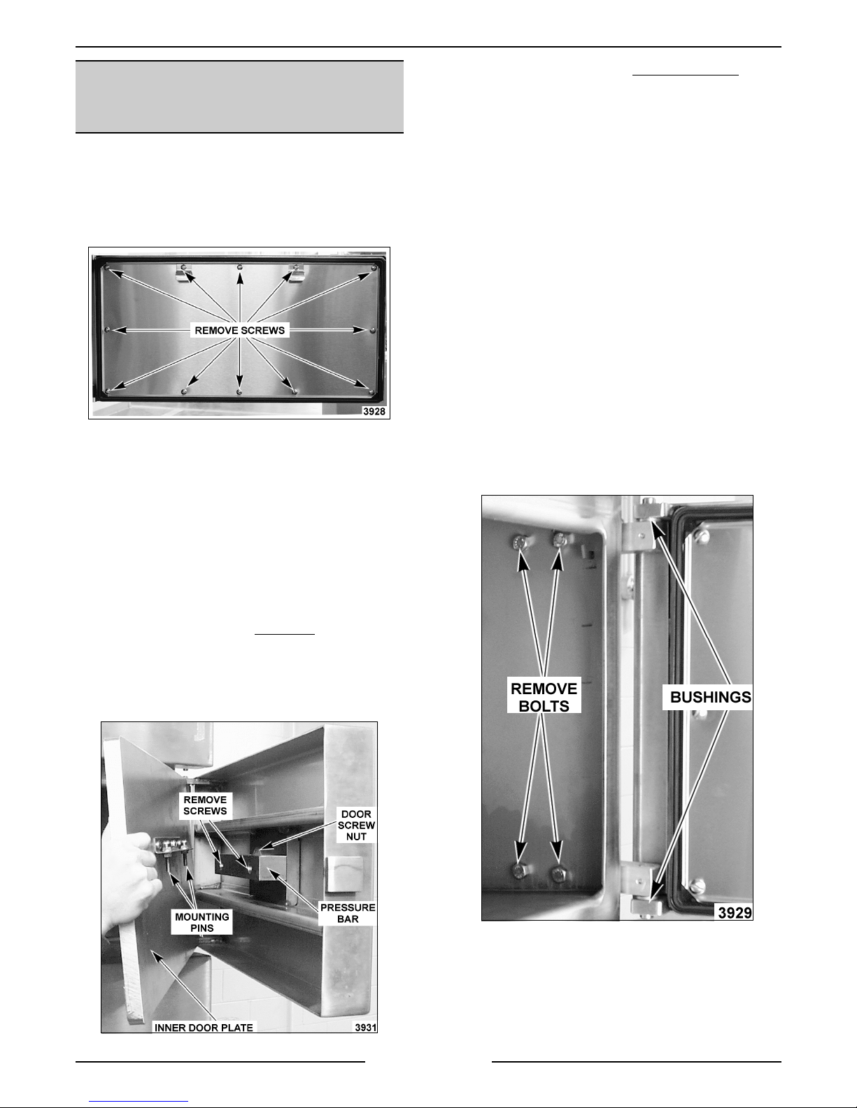
COMPARTMENT GASKET AND
DOOR SCREW NUT, DOOR AND
BUSHINGS
Gasket
1. Open the com par tment door t o be r eplaced.
2. Remove screws securin
plate to t he gasket.
3. Lift the
4. Position t he new
and rever se procedur e to install .
asket off the inner door plate.
the gasket retainin
asket on the inner door plate
4. Turn screw handle fully counter c lockwise
remove from door.
5. Remove screws mountin
the backside of the compartment door.
NOTE:
each screw. Set aside f or r euse.
6. Remove screws mountin
7. Reverse procedur e to install and c hec k for
Door and Bushing
1. Open the com par tment door t o be r eplaced.
2. Remove the ri
3. Remove the four bolts inside the compartm ent
CAUTION: Door is extremel y heavy and will drop
when bolts are removed.
A compression sprin
(bronze) to the bac k si de of the compartment
door.
proper operation.
ht side pan support inside the
compartment.
that secure the bl oc k hin
of the compartm ent.
the pressure bar to
is mounted behind
the door screw nut
es to the exter ior side
and
NOTE:
as nicks or cuts, will cause steam leaka
Door Screw Nu t
1. Open compartment door t o be serviced.
2. Turn screw handle fully cl oc k wise
3. Lift the inner door plate assembly up, until the
Dama
inner door plate assembly.
mounti n
pressure bar and set the assembly aside.
e to the gasket sealing surface, such
e.
to extend
pins are out of the holes in the
4. At this time, t he bushi n
necessary, by removin
pin on each block hin
5. Reverse procedur e to install and c hec k for
proper operation.
Page 20 of 88
s can be replaced if
the bushings from the
e.

VL SERIES STEAMERS - REMOVAL AND REPLACEMENT OF PARTS
g
g
g
g
g
ge g
g
g
g
g
g
g
g
HEATER CONTACTORS
WARNING:
POWER TO T HE MACHINE AT THE MAIN
CIRCUIT BO X. P LA CE A TAG ON THE CIRCUIT
BOX INDICATING THE CIRCUIT IS BEING
SERVICED.
1. Open the cabinet base doors, remove the two
2. Disconnect the electrical lead wires to the coil
3. Remove the screws form the base of the
4. Reverse procedur e to install and c hec k for
DISCONNECT THE ELECTRICAL
screws from the contactor box c over and l ift
cover off.
and the power supply wires from the contact or
bein
replaced.
contactor and lift out.
proper operation.
HEATING ELEMENTS
REGENERATED STEAM MODELS
(STEAM COIL)
WARNING:
POWER TO T HE MACHINE AT THE MAIN
CIRCUIT BO X. P LA CE A TAG ON THE CIRCUIT
BOX INDICATING THE CIRCUIT IS BEING
SERVICED.
WARNING:
BEFORE SERVICING THE UNIT.
1. Disconnect pipe unions in the steam suppl y line
to the coils and in the condensate dischar
line from the c oils.
2. Remove header that supplies steam to the coils
by disconnecti n
3. Remove coil c ondensate c ollection header.
4. Remove bolts securin
and pull coil for ward.
5. Clean the m atin
flan
DISCONNECT THE ELECTRICAL
SHUT OFF THE STEAM SUPPLY
e
union at each coil.
the coil being replaced
surfaces of the steam coil
e and the boiler .
WARNING:
POWER TO T HE MACHINE AT THE MAIN
CIRCUIT BO X. P LA CE A TAG ON THE CIRCUIT
BOX INDICATING THE CIRCUIT IS BEING
SERVICED.
1. Open the cabinet base doors, remove the two
2. Disconnect the electrical lead wires to the
3. Remove the bolts securi n
4. Clean the m atin
5. Check for leaks and proper operation.
DISCONNECT THE ELECTRICAL
screws from the contactor box c over and l ift
cover off.
element bein
e to the boiler and lift the el ement out.
flan
install a new flan
element .
replaced.
the heating element
surface of the boiler and
asket and heatin
6. Reverse procedur e to install a new steam c oil
asket.
and
7. Check steamer for proper operation.
Page 21 of 88

VL SERIES STEAMER - SERVICE PROCEDURES AND ADJUSTMENTS
g
ging
g
g
g
g
g
g
g
g
g
g
g
g
g
g
g
g
g
g
g
g
g
g
g
g
g
g
g
g
g
g
g
SERVICE PROCEDURES AND ADJUSTMENTS
WARNING: CERTAIN PROCEDURES IN THIS SECTION REQUIRES ELECTRICAL TEST OR
MEASUREMENTS WHILE POWER IS APPLIED TO THE MACHINE. EXERCISE EXTREME CAUTION AT ALL
TIMES. IF TEST POI NTS ARE NOT EASI LY ACCESSIBLE, DISCONNECT POWER, ATTACH TEST
EQUIPMENT AND REAPPLY POWER TO TEST.
BOILER
Inspection
It is recommended the boiler be inspected for
excessive scale and li me build up on a quar terly
basis. In hard water areas or f or steamers heavily
used, a more frequent inter val shoul d be used. This
inspection consi sts of an internal examination and
cleanin
han
water level probes. Also, a c hec k of all boiler
controls, includin
Periodic service must be perfor med as outlined in
these procedures. See “WATER CO NDITIONING”
under “GENERAL”.
WARNING: READ AND FO LLOW THE
INSTRUCTIONS ON THE CLR BOTTLE. USE
PLASTIC OR RUBBER GLOVES TO AVOID SKIN
CONTACT. I F CLR LIQUID COMES IN CO NTACT
WITH THE SKIN, RINSE WITH CLEAN WATER.
Clean-Out (All Boiler Models)
1. Turn steamer OFF and drain boiler.
2. Remove hand hole plat e and
of the boiler, an examinat ion of the two
descalers, and for lime build up on the
the pressure switches.
asket (top f r ont)
from the boiler by r emov in
then tappin
holdin
from droppin
the cover lightly to free it while
the cover stud. This prevents the cover
into boiler.
the nut and clamp,
NOTE: B oiler water capacities vary between seven
to nine
dependin
NOTE: If delimin
contact with steamer components, li
with clean water.
allons f or both gas and electric models
on the boiler si z e and B TU/KW rating.
solution accidently comes in
htly rinse off
A. M odels with Blowdown Timer
delimin
to step 9.
B. M odels without Blowdown Timer
the incomin
switch ON to cl ose the dr ain valve. Pour
delimin
to step 9.
C. Models with Delimin
Before pourin
boiler, c lean the seatin
hand hole
asket. Position the hand hole plate and
ti
supply. Turn t he power switch O N to close
the drain valve. Open t he delimin
assembly valve and pour the delimin
solution i nto the port. Close the delimin
assembly valve and proceed to step 10.
solution into boiler shell. Proceed
water supply. Turn t he power
solution into boiler shell. Proceed
Port Assembly -
deliming solution into
asket and then instal l a new
hten down. Turn of f the inc oming water
- Pour
surfaces for the
- Turn off
3. Remove old descaler retainin
present.
4. With a wire brush, or equi valent, dislod
remove all loose scale from boiler shel l. The
loose material must be either scooped fr om the
h the drain.
boiler or flushed throu
5. Check probe canister and float valve assembly
enerated models) for a scale build up and
(re
clean as necessary.
6. Check drain hol e for obstructions.
7. Inspect the condi tion of the descalers as
outlined in this section and r eplace if
necessary.
8. Mix the delimin
instructions for the chemical bein
solution according to the
springs if
used.
e and
Page 22 of 88
9. Clean the seatin
asket and then Install a new gasket. Position
hten the hand hole plate.
and ti
surfaces for the hand hole

VL SERIES STEAMER - SERVICE PROCEDURES AND ADJUSTMENTS
g
g
g
g
g
g
g
g
g
g
g
g
g
g
g
g
g
g
g
g
g
g
g
ging
g
g
10. Cooking compartment ti mers are to be in t he
OFF position. Turn the boiler switch ON and
open water valve if necessary.
11. Boiler is to operate under pressure for 90
minut es or per the instructions for the chemical
in use.
12. Drain boiler by normal methods.
13. Refill boiler and allow to heat until fully
pressurized.
14. Repeat step 13 three times.
15. The steamer is now ready for norm al operation.
Deliming Only (Models with Deliming Port
Assembly)
Boiler delimin
bi-weekly or monthly basis, dependin
should be performed on a weekly,
on the quality
of the local water supply. S ee “ WAT E R
CONDITIONING” under “GENERAL”.
On steamers usin
a water purif ication system,
follow the instructions for that system to deli me the
boiler. Only use the type of chemical recommended
or described in t he instructions for delimin
with this
type of system.
1. Turn steamer OFF and drain boiler.
2. Mix the delimin
instructions for the chemical bein
solution according to the
used.
NOTE: B oiler water capacities vary between seven
to nine
dependin
NOTE: If delimin
contact with steamer components, li
allons f or both gas and electric models
on the boiler si z e and B TU/KW rating.
solution accidently comes in
htly rinse off
with clean water.
A. Models with Blowdown Timer - Open
the delimin
delimin
delimin
assembly valve and pour the
solution i nto the port. Close the
assembly valve and proceed to
step 3.
B. Models without Blowdown Timer - Turn
off the incomin
water supply. Turn t he
power switch ON to close the drain valve.
Open the delimin
pour the deli min
Close the deli min
assembly valve and
solution i nto the port.
assembly valve and
proceed to step 3.
3. Top compartments are to be in the OFF
position. Turn the boil er switc h ON and open
water valve if necessary.
4. Boiler is to operate under pressure for 90
minut es or per the instructions for the chemical
in use.
5. Drain boiler by normal methods.
6. Refill boiler and allow to heat unti l ful ly
pressurized.
7. Repeat step 6 three times.
8. Steamer is now ready for norm al operation.
Descaler
The descaler is accessible throu
openin
cylindr ical core, and han
. It i s a coiled wire wound around a solid
s by an open loop from the
h the hand hole
shell's horizontal stay rod, about 4 inches from the
front of the shell . If t he wir e is eaten throu
h, or if
the core of the descaler is eaten away to hal f its
inal size, a new descaler should be installed.
ori
To install a new descaler, stretch its wire coil so the
descaler han
minimum water level in the boi ler, but han
The descaler m ust not contact the bottom of the
boiler shell, elect r ic heatin
re
Page 23 of 88
s with its core completely below the
free.
element s or
enerating steam coils.

VL SERIES STEAMER - SERVICE PROCEDURES AND ADJUSTMENTS
g
g
g
g
g
g
g
g
g
gaug
g
g
g
g
g
g
g
g
gg
g
g
g
g
g
g
g
g
g
g
g
g
g
g
g
g
g
g
g
gaug
g
g
g
g
g
WATER LEVEL CONTROL(S)
TEST
Loose electric al connections may prev ent the heat
from comin
An accumulation of lime scale on or near the water
level sensin
water (moist) on the probe surface and
readin
ive a false reading. These conditions may prevent
the boiler from fillin
will result in damage to the heati ng element s on
electric models or t o the boiler on
models.
WARNING:
POW E R TO BE APPLIED TO THE UNIT DURING
THE TEST. USE EXTREME CAUTION AT ALL
TIMES.
Solid State - Low level Cut-Of f & Differential
Control
1. Turn the power switch ON.
2. Ensure that water is fillin
A. Confirm that water supply valve(s) are
B. Observe boiler water level in the water
3. Check the volta
the board. Meter shoul d r ead 120V A C.
A. If volta
B. If boiler fill solenoid is receivin
C. If boiler fill solenoid is not
4. If boiler is fillin
reaches the low level cut- off ( LLCO) probe,
LLCO relay should ener
contacts, heat source shoul d c ome on
(standard model s onl y ) and LLCO LED will
li
on or may cause the boiler to overfill.
probes may cause them to retain
ive a false
. Also, a crac k ed or damaged insulator may
or cause dry firing. Dry firin
as or electri c
THE FOLLOWI NG ST EPS REQUIRE
the boiler .
turned on.
level
approximately 11 minutes.
(HL) relay should ener
contacts and the HL LED should li
The boiler fill solenoid should then
ener
boiler fill solenoid valve is receivin
120VAC and water is flowing through it.
no water is fl owin
malfunction or valve for clo
solenoid is bad or port s can not be
cleaned, then r eplace boiler fill solenoid
and check for pr oper oper ation.
and the electr ical connect ions have been
checked, then t he HL r elay is not bein
energized or the HL-3 c ontacts are not
closin
and check for pr oper oper ation.
ht.
e. If empty, boiler should f ill in
e across terminals L1 & L2 on
e is correct t hen the high level
ize, closing HL-3
ht up.
ize and start filling the boiler. Verify
power but
, inspect fill solenoid for
ed ports. If
receiving power
. Replace water l evel c ontrol board
properly, when the water level
ize closi ng LLCO-2
5. Once the water level r eac hes the hi
(HL) probe, the inverse l atchin
board (solid state) shoul d ener
throu
h the low level probe (LL) and ILR-1
contacts. Wit h ILR-2 contacts open, t he HL
relay is de-ener
With the HL-3 cont ac ts open, the boiler fil l
solenoid should de-ener
fill.
6. If water is in the boil er but is not bein
by the water level probes, t he pr obes may need
cleaned and/or boiler delimed. See “Water
Level Probes” as outlined below for inspectin
and cleaning of probes and “BOILER” for a
procedure on boil er inspection, clean-out and
delimin
7. Turn the power switch OFF and disconnect the
lead wire f r om each probe. Check the probes
as outlined bel ow.
A. Wi th an ohmmeter, check between the
NOTE:
water quality and pr obe c ondition.
8. After performin
water level control boards operation, if the
control is not functionin
replace it and check for pr oper oper ation.
Electro Mechanical - Low level Cut-Off &
Differenti al Control
WARNING:
POW E R TO BE APPLIED TO THE UNIT DURING
THE TEST. USE EXTREME CAUTION AT ALL
TIMES.
1. Ensure that water is fillin
A. Confirm that water supply valve(s) are
B. Observe boiler water level in the water
C. Verify boiler fill solenoid valve is receivin
2. Check for correct volta
low level and different ial water level controls.
A. Turn the water supply valve off then turn
.
probe terminal and boiler shell. An open
circui t should be present when the boiler is
empty. If resistance is present, remove
and inspect the probes as outlined below
under “Water Level Probes”. When the
boiler is full of water, a resistance r eadin
should be measurable bet ween the probes
and boiler.
The actual r esi stanc e r eadin
THE FOLLOWI NG ST EPS REQUIRE
turned on.
level
120VAC and water is flowing through it.
the power switch ON. Check t he input
volta
should read 120VAC. If volta
proceed to step 2B. I f volta
find the source of the problem and repeat
this step.
ized and HL LED goes out.
ize and stop the boi ler
steps 1-5A and verifying the
as described, then
the boiler .
e.
e being applied to the
e across terminals 1 & 2. Meter
h level
relay of the
ize and lock
detected
will depend on
e is correct
e is incorrect,
Page 24 of 88

VL SERIES STEAMER - SERVICE PROCEDURES AND ADJUSTMENTS
g
g
g
g
g
g
g
g
g
g
g
g
g
g
g
g
g
g
g
g
g
g
g
g
g
g
g
g
gaug
g
g
B. Wi th the boiler empty, chec k the voltage
across terminals 9 & 10. Meter should
read 300 to 350VAC. I f volta
proceed to step 3. If volta
approximately 30V A C then the internal
contactor is ener
scaled ov er and moist and/or have a
dama
See “Water Level Probes“ listed below for
inspectin
procedures on boiler inspection, clean-out
and delimin
volta
level control is bad and the control should
be replaced. Check for proper operat ion
after r eplacement.
3. If water is in the boil er but is not bein
by the water level probes, t he pr obes may need
cleaned and/or boiler delimed. See “Water
Level Probes“ listed below for inspectin
cleanin
boiler inspection, clean-out and deli min
4. Turn the power switch OFF and disconnect the
lead wire f r om each probe. Note the locati on of
the probes and the number of the wire
connected to i t.
A. Chec k the resistance between the probe
terminal and boil er shel l. An open
should be present when the boiler is
empty. If resistance is present, remove
and inspect the probes as outlined below
under “Water Level Probes”. A resi stanc e
readin
between the probes and boiler shell
(
NOTE: The actual resistanc e r eadin
water quality and pr obe c ondition.
5. If after performi n
not functionin
controls operation as outlined in “W A TER
LEVEL CONTROLS” under “ELECTRICAL
OPERATION”.
6. After checkin
cut off or differential water l evel c ontrol does
not appear to be functioni n
replace the control and check for proper
operation.
Water Level Prob es
WARNING: DISCONNECT THE ELECTRICAL
POWER TO T HE MACHINE AT THE MAIN
CIRCUIT BO X. P LA CE A TAG ON THE CIRCUIT
BOX INDICATING THE CIRCUIT IS BEING
SERVICED.
ed insulator giving a false reading.
and cleaning and “BOILER” for
e, then contactor coil on the water
and “BOILER” for procedures on
should only be m easurable
round) when the boiler is full of water.
properly, veri fy the water l evel
the abov e items, if the low level
ized but the pr obes are
. If y ou do not read any
steps 1-4 and the control is
as described, then
e is correct
e reading is
detected
and
.
circuit
will depend on
2. If lime scal e build up is evident on t he pr obe,
thorou
the probe and insulat or . Do not
abrasiv e on the insulator; use a sof t cloth.
3. Inspect the probes f or a c r ac k ed or dama
insulator. If a probe appears to be dama
replace it with a new one and proceed to step
5. If a pr obe does not appear to be dama
then proceed to step 4.
4. Check throu
top of t he c anister assembly for the presence of
water. Water must drain from the probe
canister and if in doubt, pour water into the
canister and observe that it drains quickly. If
water fails to drain from the canister, rem ove
the cover or canister assembly and clean.
5. Reverse procedur e to install and c hec k for
proper operation.
hly clean it removing all deposit s from
use any thin
ed
ed,
ed
h the probe socket opening in the
CYCLING AND HIGH LIMIT
PRESSURE SWITCHES
(GAS AND ELECTRIC MODELS)
WARNING: THE FOLLOW I NG ST EPS REQUIRE
POW E R TO BE APPLIED TO THE UNIT DURING
THE TEST. USE EXTREME CAUTION AT ALL
TIMES.
Remove the boil er c ontrol box c over as outl ined
under “CYCLING AND HIGH LI MI T PRESSURE
SWIT CHES (GAS AND ELECTRIC MODELS)” to
access the two controls. The pr essure switch on the
ht is the cycling or prim ar y c ontrol; the one on the
ri
left is the hi
switches, dif ferin
Turn the power ON and let the boiler c ome up to
pressure. Close and seal one of t he c ompartm ent
doors, set a time past 5 minut es on the c ook in
tim er , pull the steam control ar m handle forward and
turn the compartment power switch O N to exhaust
pressure from the boiler. Observe boi ler pressure
e readings for several cycles and compare
them with the pressure settin
If t he r eadin
described below.
h limit contr ol. They are identical
only in t heir settings.
s in the chart.
s differ, adjust t he pr essure settings as
1. Remove the cover ov er the water level probes
and disconnect the lead wire from each probe.
Note the location of eac h pr obe and the
number of the wire connected t o it. Rem ove
each water level probe for exam ination.
Page 25 of 88
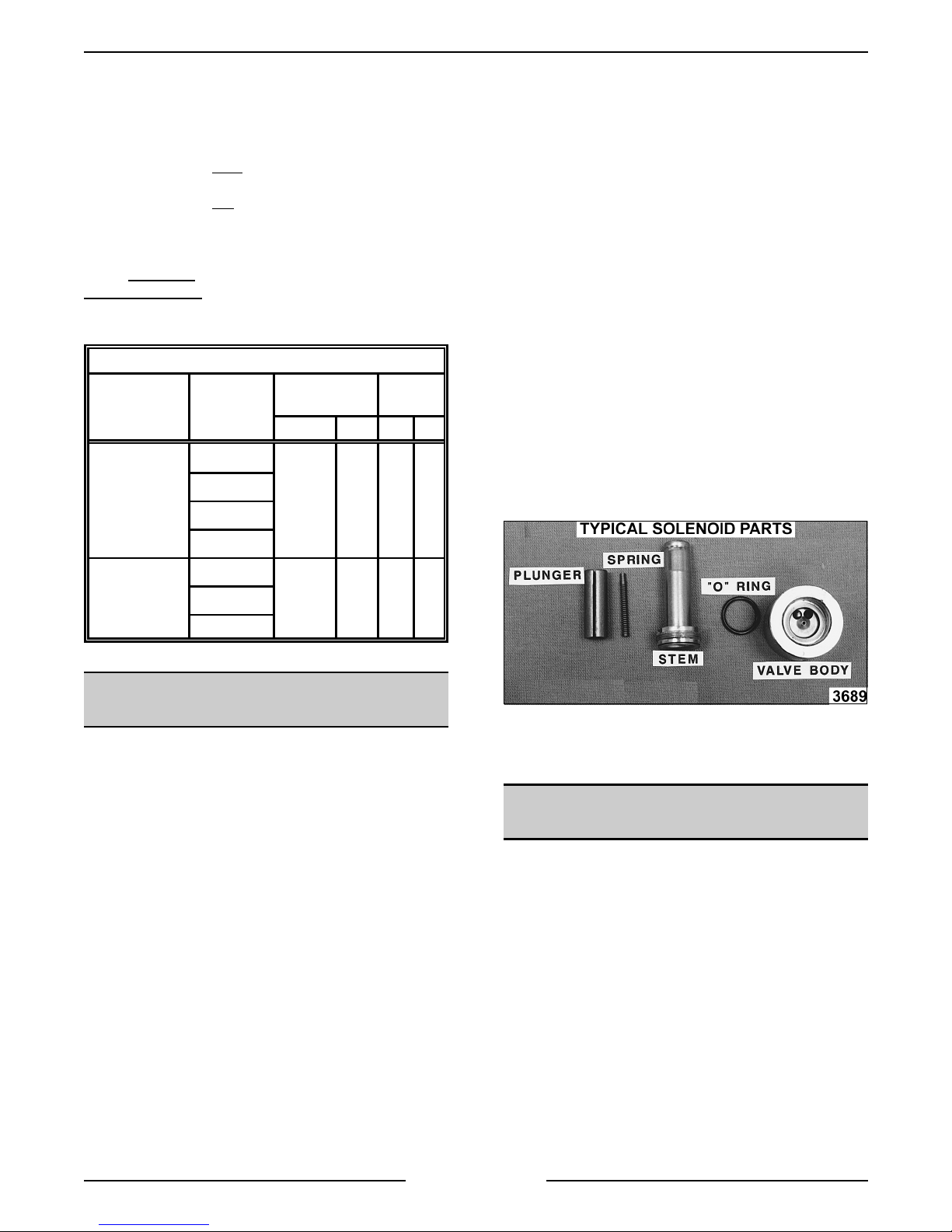
VL SERIES STEAMER - SERVICE PROCEDURES AND ADJUSTMENTS
g
g
g
g
g
g
g
g
g
g
g
g
g
gg
g
g
g
g
g
g
g
g
g
g
g
g
g
g
g
g
gaug
g
Two slotted and square headed adjustment screws
extend thr ou
pressure scale and indicat in
h the sight glass window to indicate t he
throu
approximate pressure settin
directly above the ri
h the top of the switch case. A
pointers are visibl e
. The adjustment screw
ht side pointer c hanges the
cut-out (off) set point and the adjustment screw
directly above the left
side pointer changes cut-in
(on) set point. A djust the screw to obtain t he pr oper
cut-out (off) settin
to obtain t he pr oper c ut-in (on) settin
screw clockwise
countercloc k wise
The pressure settin
fir st, then adjust the ot her screw
. Turn the
to increase the pressure setting and
to decrease the pressure setting.
s for each switch are listed
below.
BOILER PRESSURE SETTINGS (PSI)
CONTROL
TYPE
With
Compartment
Pressure
Regulating Valve
VL
MODELS
PS
AS
SS
MS
CYCLING HIGH
LIMIT
ON OFF ON OFF
911615
1. Remove the coil assembly f r om the valve stem
by liftin
the solenoid valve and slidin
up on the retaining cap at the top of
the metal cover
plate off.
2. Clamp t he body of the valve in a vise.
3. Mark a scribe l ine on the stem nut to the v alve
body for proper r eti
4. Remove the stem lockin
htening.
nut to remove the
stem f r om the valve body.
5. All parts are now accessible for i nspect ion and
cleanin
NOTE:
dama
Do not reuse dama
.
If internal solenoid parts appear to be
ed or worn, then replace the solenoid valve.
ed or worn parts. No internal
solenoid parts are avail able as a servic e
replacem ent.
A. Chec k r ubber seal on bottom of plun
B. Chec k plun
C. Check O-rin
er spring.
in valve body.
er.
D. Check ports in valve body.
With-Out
Compartment
Pressure
Regulating Valve
AS
46215SS
MS
FILL AND COLD WATER
SOLENOID VALVES
WARNING:
POWER TO T HE MACHINE AT THE MAIN
CIRCUIT BO X. P LA CE A TAG ON THE CIRCUIT
BOX INDICATING THE CIRCUIT IS BEING
SERVICED.
Check to assure the solenoid valve is receivin
power. If t he sol enoid valve is receiving power but
the v alve is not openin
malfunctionin
check for pr oper oper ation. If the solenoid valve is
receivin
openin
then the valve ports may be clo
valve component malfunct ionin
valve further, foll ow the proc edur e outlined bel ow.
Disassembly
NOTE:
removed for c leanin
This will prevent dama
when the stem is rem oved from the body.
DISCONNECT THE ELECTRICAL
, the coil may be
. Replace the sol enoid valve and
power and the valve appears to be
but little or no water i s flowing through it,
ed with debris or a
. To check solenoid
It is recommended that the valve be
as outlined i n this procedure.
e to the lines and fittings
6. Reverse procedur e to install .
COMPARTMENT PRESSURE
ADJUSTMENT
Remove the left side panel from t he boiler base to
access the compartment pressure re
If t he steamer is equipped wit h the compartment
pressure re
operatin
ulating valve and t he steamer is
, set the pressure regulating valve t o r ead
6 psi on the compar tment
screw at the top clock wise to increase the pressure
and countercloc k wise to dec r ease. If the steamer is
not equipped with t he c ompartm ent pressure
ulating valve, then the compartment will cycle at
re
the same pressures of the boiler. A mechanical
pressure relief valve serves as a safety backup
control and is pre-set for a maximum of 8 psi.
ulating valve.
e. Turn the hex head
Page 26 of 88

VL SERIES STEAMER - SERVICE PROCEDURES AND ADJUSTMENTS
g
g
g
g
g
gaug
g
g
g
g
g
g
g
g
g
g
g
g
g
g
g
g
g
g
g
g
g
g
g
g
g
HIGH LIMIT THERMOSTAT
WARNING:
POWER TO T HE MACHINE AT THE MAIN
CIRCUIT BO X. P LA CE A TAG ON THE CIRCUIT
BOX INDICATING THE CIRCUIT IS BEING
SERVICED.
Remove thermostat (bi-metallic disk type) as
outlined under “ HIGH LIMIT THERMOSTAT” in
“REMOVAL AND REPLACEMENT OF PARTS”.
Inspect the temperature sensin
for corr osi on or r ust. Clean mount in
surfaces befor e r emountin
metal - to-metal contact i s essential for proper
functionin
performed at least once a year . If t her mostat matin
surface can not be throughly cleaned or is severely
pitted and rusted, then replace and chec k for proper
operation.
DISCONNECT THE ELECTRICAL
side of ther mostat
and thermostat
or replaci ng. A good
of the t her mostat. This servic e must be
BOILER NOT FILLING WITH
WATER
Ensure that water to the steamer is turned on, then
turn power switch ON. After approximat ely 10
minut es, if no water i s observed in the water level
e sight glass, then check for a problem with the
boiler fill solenoid valve, water level control(s) or the
water level probes. See “WATER LEVEL
CONTROL TE S T”. Also, ”water hammerin
supply line, in conjunction with a check valve can
cause a high water pressure pocket in the water line
to the fill solenoid valve. The f ill solenoid valve will
not be able to overcome this pressure and operate
to supply the boi ler with water. Shut off the water
supply and reli eve the pressure in the line. Turn the
water supply back on and check for proper
operation.
NOTE
: To eliminat e this problem , the customer
must install a “water hammer suppression device” in
the supply line to the boiler.
WARNING:
POWER TO T HE MACHINE AT THE MAIN
CIRCUIT BO X. P LA CE A TAG ON THE CIRCUIT
BOX INDICATING THE CIRCUIT IS BEING
SERVICED.
Scalants may be coverin
probe
level in the boiler. Remove and thorou
water level probes to rem ove scalant s and l ime
build up. A lso, Check throu
openin
presence of water.
Water must drai n from the probe canister and i f in
doubt, pour water into the canister and observe that
it drai ns qui c k ly.
DISCONNECT THE ELECTRICAL
the water level contr ol
iving a false i ndication of a sufficient water
h the probe socket
in the top of the canister assembly for the
” in the
hly clean the
If water fails to dr ain from the canister, remove the
cover or c anister assembly and clean. These
conditi ons i ndicate extremely poor water quality
bein
supplied to the boiler and/or boiler cl ean out
and delimin
The water condition must be cl ear ed up imm ediately
with a proper water conditioner to avoid further
problems with the steamer. Re-install t he water level
probes and canister assembly ( if appl icable).
Perform a boiler inspection, clean-out and delimin
procedure as outli ned under “ B OILER”. Check for
proper operation.
Water may be drainin
blowdown solenoid valve as qui c k ly as it’s fed to the
boiler. Loose wirin
scale trapped in the valve seat may prevent the
valve from closin
Newer steamer models use a plun
raises and lowers to permi t steam/water flow out of
boiler. If debri s has accumulated around the water
orif ice, the pl un
off the openin
the solenoid as outl ined in “FI LL A ND COLD
WATER SOLENOID VALVES”. Remove any debris
found on seali n
the solenoid valve still does not function properly,
replace it with a new val ve and check for proper
operation.
Older steamer models have a movable blade and
when closed, the blade reacts as a
should be free t o mov e full y down into the v alve
pocket (proj ec tion at bott om of valve) so that t he
pierced hole in the blade al i
body openin
bottom of the valve pocket, then the blade will not
move into the pocket completely. If this symptom is
suspect, remove the solenoi d as outlined in “FILL
AND COLD WATER SOLENOID VALVES”.
NOTE:
assembly bolt s hol din
remove the loose internal parts. Remove any debr is
found on seali n
the solenoid valve still does not function properly,
replace it with a new val ve and check for proper
operation.
has not been performed.
through an open boiler
, a burned out coi l or partic les of
.
er type rod that
er may not seat pr oper ly to close
. If this symptom is suspect, remove
surfaces, reassembl e and install. If
uillotine that
ns perfectly with the
. If debr is has accumulated in the
On this valve body, remove t he two
the brass body together and
surfaces, reassembl e and install. If
BOILER BLOWDOWN DRAIN
SOLENOID VALVE
The water contained in the boil er , being under
pressure, should be blown throu
noticeabl y visi ble exhaustin
Daily boiler blowdown is essential
operation and component li fe by rem ovin
and scalants that may be lod
the boiler .
h this valve and be
out the steamer dr ain.
to proper
sediment
ed in the chamber of
Page 27 of 88
 Loading...