

Vulcan-Hart VI2, VI3, VI33, VI22, VI23 Service Manual
SERVICE MA NUAL
INDUCTION
COOKERS
MODEL ML
VI2 114713
VI3 114714
VI22 114715
VI33 114716
Model VI22 shown
This Manual is prepared for the use of trained Vulcan Service
Technicians and should not be used by those not properly
qu alif ied. If yo u have attend ed a Vulcan Service School for this
product, you may be qualified to perform all the procedures
described in this manual.
Thi s manu al i s no t i nten ded to be al l en comp assi ng . I f you have
not attende d a Vulcan S ervic e School for this produ ct , you should
read, in its entirety, the repair procedure you wish to perform to
determine if you have the necessary tools, instruments and skills
required to perform the procedure. Procedures for which you do
not have th e n ecessary too ls, in strument s and skills should be
performed b y a trained Vu lcan Service Technician.
Reproduction or other use of this Manual, without the express
written consent of Vulcan, is prohibited.
VI23 114717
- NOTICE -
A product of VULCAN-HART LOUISVILLE , KY 40201-0696
Form 24591 ( Rev. A, 12-98) Supercedes (5-97)

TABLE OF CONTENTS
GENERAL............................................................................. 3
Introduction ........................................................................ 3
How to Distinguish a Usable P an .................................................... 3
Usable Pans Which Have Slower Rates of Heat Transfer.................................. 3
Recomm ended P ans ............................................................. 4
Unusable Pans.................................................................. 5
Tools ............................................................................. 5
Location........................................................................... 5
Controls........................................................................... 5
Specifications ...................................................................... 6
Cleaning .......................................................................... 6
REMOVAL AND REPLACEMENT OF PARTS ................................................. 7
Top Cover ......................................................................... 7
Inverter Assembly ................................................................... 7
Fan Motors ........................................................................ 8
Controll er Board, Led and Potent iometer .................................................. 9
Knob Gasket ....................................................................... 9
Inverter Coil........................................................................ 9
High Volt age B oard ................................................................. 10
Low Voltage Board .................................................................. 10
EMI Board ........................................................................ 11
Fuse on EMI Board ................................................................. 11
Thermistor, Tension Spr ing and Support ................................................. 11
SERVICE PROCEDURES AND ADJUSTMENTS .............................................. 12
Thermistor Test .................................................................... 12
Controller Board Potentiometer Test .................................................... 12
High Volt age B oard Test ............................................................. 12
Inverter Coil Test ................................................................... 13
Power Output Adjustment ............................................................ 13
Access Hole Modification............................................................. 16
Transformer Test ................................................................... 18
ELECTRICAL OPERATION .............................................................. 18
Component Func tion ................................................................ 18
Component Locat ion ................................................................ 19
Sequence of O per ation .............................................................. 20
Plug Layout ....................................................................... 21
Wiring Diagram .................................................................... 22
TROUBLESHOOTING .................................................................. 24
© VULCAN 1997, 1998
2
INDUCTION COOKERS - GE NE RA L
GENERAL
INTRODUCTION
Model VI2 is a single 2.2KW cooker.
Model VI3 is a single 3KW cooker.
Model VI22 is a double 2.2KW cooker.
Model VI33 is a double 3KW cooker.
Model VI23 is a double cooker with one 2. 2K W cook er and one 3K W cooker .
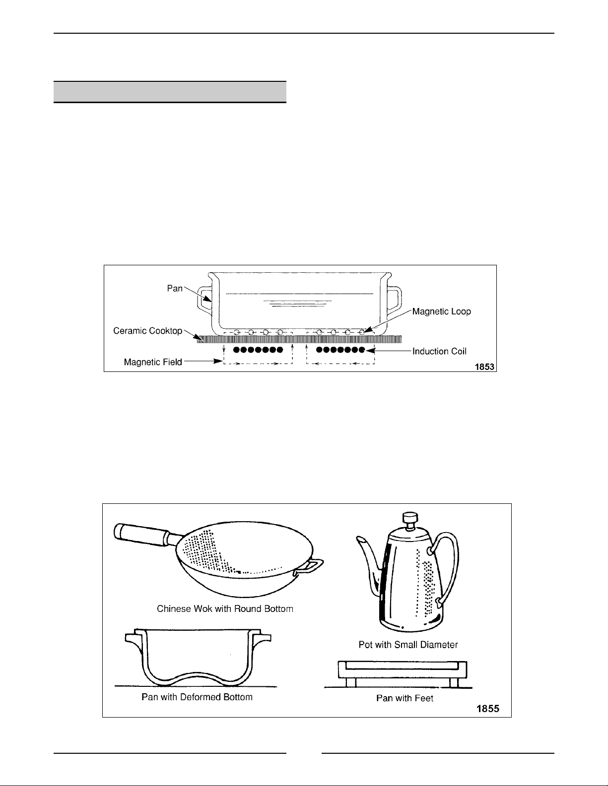
The induction cooktop will not heat the way a resistance heater conduct s to the pan. A magnet ic induction coil is
beneath the ceramic top. This coil c reates a magneti c fiel d that requires a steel or iron pan to complete the
magneti c loop. If the pan is not present, the cooktop stays in a “c ool” ready state wit hout using much cur r ent. It i s
necessary to use iron or steel pans, or special pans designed for induction use. Cer amic, glass, pottery and some
special stai nless steel pans will not complete the magnetic loop and, t her efore, will not heat properly, and should
not be used.
How to Distinguish a Usable Pan
Put the pan filled with water on the center of the cooktop and turn the contr ol knob to the desir ed c ook ing level.
The indicator light will light continuously for a usable pan and will blink for an unusable pan.
Usable Pans Which Have Slower Rates of Heat Transfer
Pans with smaller bottom diameter or partially contacting bottom may be usable but will have reduced heat
transfer r ates. These may be accept able for warming but not for frying.
3
INDUCTION COOKERS - GE NE RA L
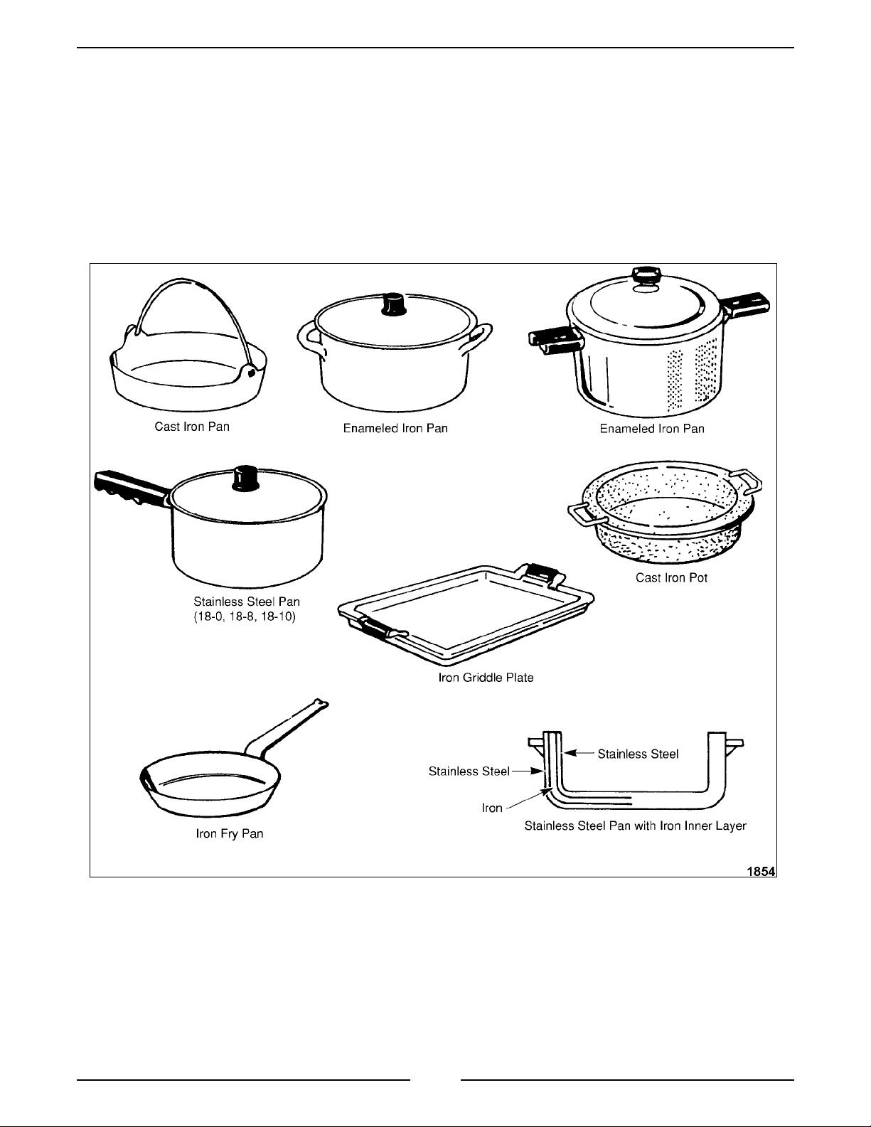
Recommended Pans
Pans made of c ast iron, enameled iron, or stainless steel with an i r on inner layer are r ecommended. Stainl ess
steel pans with 18-0, 18-8, 18-10, and 18-Cr m aterial ar e ac c eptable if a magnet will attach itself to the pan and if
the shape of the pan is acceptable. P ans with a flat bottom 5" to 10½" in diameter are recommended. Thin pans
may deform during heating; a t hicker wall and bottom are rec ommended. P ans made of 18-8 stai nless steel and
pans with a small er diameter bottom may hav e sl ower rat es of heat transfer.
4
INDUCTION COOKERS - GE NE RA L
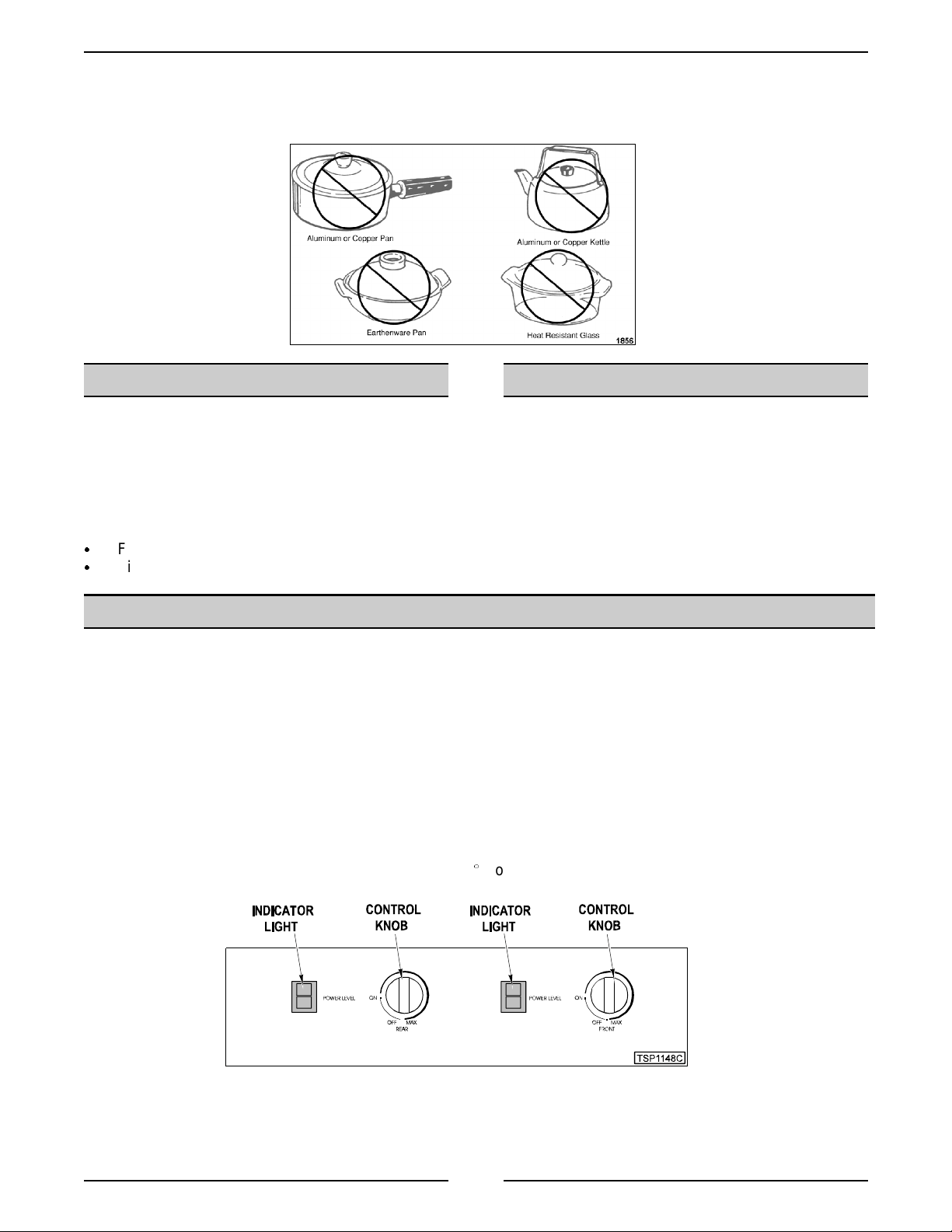
Unusable Pans
Pans made of por celain, ear thenware, heat-resistant glass, copper, or aluminum ar e not recommended because
they do not transfer heat from the magnetic induction field.
TOOLS
• Standard set of hand tools
• VOM with AC current tester (Any VOM with a
sensitivity of at least 20,000 ohms per volt can
be used.)
• Thermal compound Part # 819643
• Demeyere sauce pan with 26c m top opening
and 24cm bott om PMI Par t # 424971-1
Fiberglass screwdriver Part # 424998-1
&
Field S ervice Grounding Kit Part #TL-84919
&
Position the cooktop on a suitable level countertop
surface. Do not locate the cook top near fryers, a hot
stove, or over an oven. The electri c al controls i nsi de
the cooktop will shut down if they overheat (above
110°F). Refer to the Installation and Operation
Manual f or complete install ation instruc tions.
LOCATION
CONTROLS
Control Knob Turn counterc lockwise to OFF ; clockwise to desir ed c ooking level.
Indicator Light:
On Indicates that power is ON and at what cooking lev el.
Blinking If t he indicator light bl inks continuously , it indicates the cookt op is in stand-by m ode. This
means no pan is detect ed and heat is OFF. Cook top will shut off in 3 minutes.
If cook top is in stand-by and has shut off after 3 minutes, it must be reset. Reset cooktop by
turning cont rol knob to OFF, then ON to desired cooking level.
If t he indicator light bl inks intermittently f or 2 or 3 seconds and then stops, it indicates an
elevated cooking temperature of 380(F or higher. This is norm al. The cooktop is ensuring
that maximum int er nal temper atures are not exceeded.
DOUBLE COOK E R CONTROLS SHOWN
5
INDUCTION COOKERS - GE NE RA L
SPECIFICATIONS
MODEL VOLTAGE PLUG
TYPE
VI2 208/60/1
220/240/60/1
VI3 208/60/1
220/240/60/1
VI22 208/60/1
220/240/60/1
VI23 208/60/1
220/240/60/1
VI33 208/60/1
220/240/60/1
6-20P 10.6
6-20P 14.6
6-30P 21.2
6-30P 25.2
6-30P 29.2
MAX.
AMPS
9.1/9.1
12.3/12.5
18.2/18.2
21.4/21.6
24.6/25.0
BREAKER
CLEANING
WARNING:
BEFORE CLEANING.
Clean the ceramic cooktop surface by using a c loth
moistened in warm water, or a solut ion of det er gent
and warm water. For stubbor n stains, ScotchBr ite or
a soft paste of cleanser may be used; do not use
abrasiv e materi als or harsh scouring acti on bec ause
this could damage the surfac e.
DISCONNECT ELECTRICAL POWER
SIZE
15
15
15
15
30
30
30
30
30
30
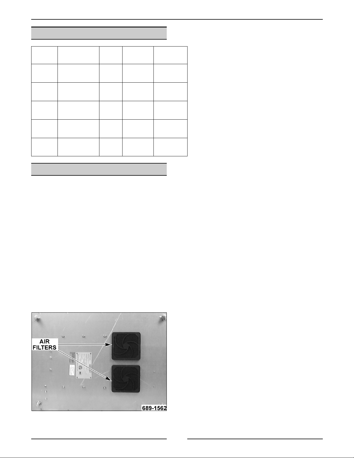
Snap out air fil ters located on the bot tom of the
cooktop and wash them i n a si nk . Dry filters before
reinstalling.
NOTE:
must be kept clean to prevent unit from overheating.
Keep area around unit clear to i nsure proper air
circulation.
Do not operate without filters in plac e. Fil ters
6
INDUCTION COOKERS - REMOVAL AND REPLACEMENT OF PARTS
REMOVAL AND REPLACEMENT OF PARTS
TOP COVER
WARNING:
1. Remove the screws securing the top cover to
the back of the unit.
2. Turn the unit on its side to acc ess and rem ove
the screws securing the cover to the bottom.
3. Put the unit upright and pull the top cover
straight off so not t o smear the thermal
compound.
4. Disconnect the lead wires at the controller
board if necessary.
5. Reverse proc edur e to install .
NOTE:
applied to c enter of inverter coil to contact top c over
when it is installed.
UNPLUG UNIT BEFORE SERVICING.
There must be suffi c ient thermal com pound
6. Remove control ler board and potentiometer as
outlined in “CONTROLLE R B OARD, LED AND
POTENTIOMETER”.
7. Remove six screws securing inverter asse mbly
to the base.
8. Reverse proc edur e to install .
INVERTER ASSEMBLY
WARNING:
1. Remove the top cover as outlined under “TOP
COVER”.
2. Identify and disconnect the fan plugs.
3. Remove any cable t ies securing fan wir es to
inverter frame.
4. Disconnect power leads from terminal block
and remove screws securing terminal bloc k to
base.
UNPLUG UNIT BEFORE SERVICING.
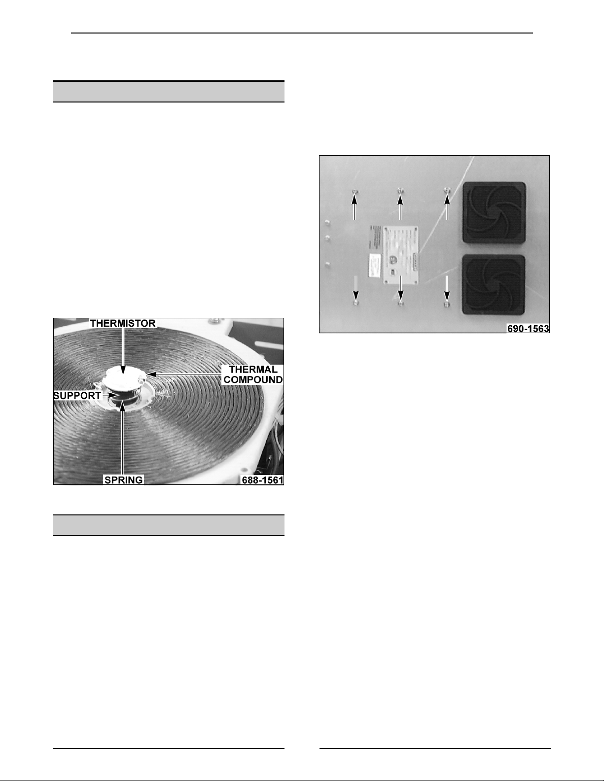
9. Apply a liberal amount of t her mal compound to
thermistor in center of inverter c oil to cont ac t
top cover as noted in “TOP COVER”.
10. Adjust power output as outlined under
“POWER OUTPUT ADJUSTMENT”.
5. Remove cable clamp securing ferrite filter on
ground wire.
7
INDUCTION COOKERS - REMOVAL AND REPLACEMENT OF PARTS
FAN MOTORS
WARNING:
1. Remove the top cover as outlined under “TOP
COVER”.
2. Disconnect the lead wire plug for the fan motor
being removed.
Units Bui lt Before 11/14/ 97
1. Intake fan only:
A. Snap off filters located underneath unit.
B. Remove screws securing fan housing to
C. Remove f an housi ng.
D. Remove f an from fan housing.
2. Discharge fan:
A. Remove fan.
UNPLUG UNIT BEFORE SERVICING.
base.
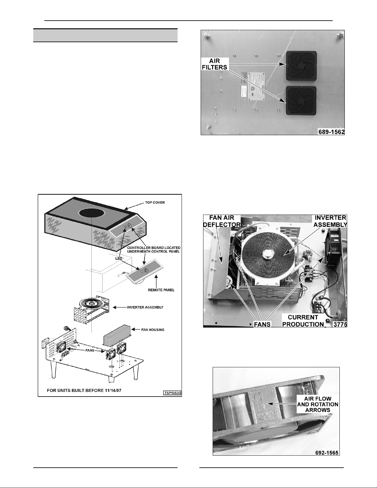
Current Production Units
1. Intake fan only:
A. Snap off filters located underneath unit.
B. Remove screws securing fan air deflector
to base.
C. Remove f an air deflector.
D. Remove rem aining screws securing fan to
be removed.
2. Reverse proc edur e to install .
NOTE:
flow and rotation. Air fl ow is entering unit through
base and exiting out rear of unit.
8
Fans have arrows indicating direction of air
 Loading...