

Vulcan-Hart VHL3 & VH3616, MHB24G, VH3616D ML-136002, VH3616E, VH3616G Installation & Operation Manual
...
INSTALLATION &
OPERATION MANUAL
VHX24, VHL2, VHL3 & VH3616 SERIES FOOD
STEAMERS & MHB24 SERIES STEAM
GENERATORS
MODELS
VHX24E ML-136033
VHX24E5 ML-136034
VHX24G ML-136031
VHX24G5 ML-136032
VHX24D ML-136035
VHX24D5 ML-136036
VHL2G ML-126323
VHL3G ML-126324
VHL2E ML-126855
VHL3E ML-126856
VHL2D ML-126858
VHL3D ML-126859
MHB24E ML-126857
MHB24G ML-114954
VH3616G ML-136000
VH3616E ML-136001
VH3616D ML-136002
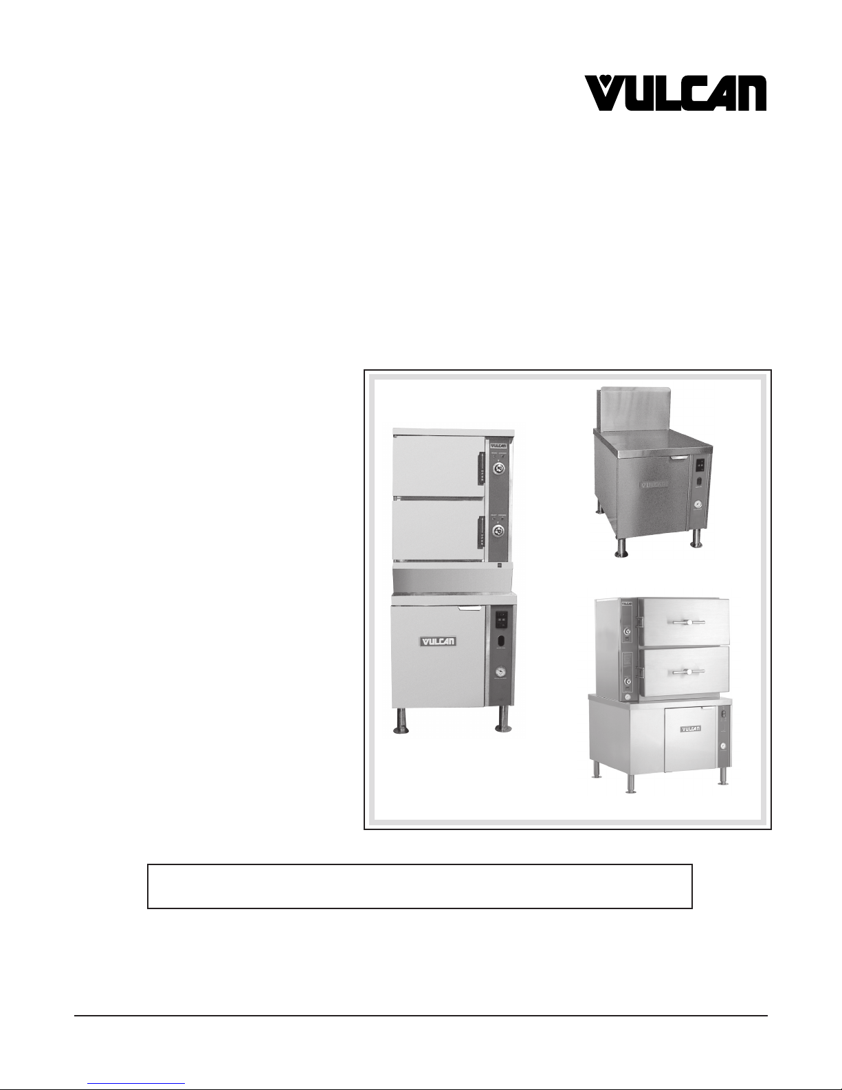
Model VHX24E
Model MHB24G
Model VHL2G
For additional information on Vulcan-Hart or to locate an authorized parts
and service provider in your area, visit our website at www.vulcanhart.com
VULCAN-HART P.O. BOX 696, LOUISVILLE, KY 40201-0696
DIVISION OF ITW FOOD EQUIPMENT GROUP, LLC TEL. (502) 778-2791
WWW.VULCANHART.COM FORM 35419 (Dec. 2004)

IMPORTANT FOR YOUR SAFETY
THIS MANUAL HAS BEEN PREPARED FOR PERSONNEL QUALIFIED TO INSTALL GAS
EQUIPMENT, WHO SHOULD PERFORM THE INITIAL FIELD START-UP AND
ADJUSTMENTS OF THE EQUIPMENT COVERED BY THIS MANUAL.
POST IN A PROMINENT LOCATION THE INSTRUCTIONS TO BE FOLLOWED IN THE
EVENT THE SMELL OF GAS IS DETECTED. THIS INFORMATION CAN BE OBTAINED
FROM THE LOCAL GAS SUPPLIER.
IMPORTANT
IN THE EVENT A GAS ODOR IS DETECTED, SHUT DOWN
UNITS AT MAIN SHUTOFF VALVE AND CONTACT THE LOCAL
GAS COMPANY OR GAS SUPPLIER FOR SERVICE.
FOR YOUR SAFETY
DO NOT STORE OR USE GASOLINE OR OTHER FLAMMABLE
VAPORS OR LIQUIDS IN THE VICINITY OF THIS OR ANY
OTHER APPLIANCE.
WARNING: IMPROPER INSTALLATION, ADJUSTMENT,
ALTERATION, SERVICE OR MAINTENANCE CAN CAUSE
PROPERTY DAMAGE, INJURY OR DEATH. READ THE
INSTALLATION, OPERATING AND MAINTENANCE
INSTRUCTIONS THOROUGHLY BEFORE INSTALLING OR
SERVICING THIS EQUIPMENT.
IN THE EVENT OF A POWER FAILURE, DO NOT ATTEMPT TO
OPERATE THIS DEVICE.
© VULCAN-HART, 2004
– 2 –

TABLE OF CONTENTS
GENERAL 5
INSTALLATION 5
Unpacking 5
Installation Codes and Standards 5
Leveling — All Steamers & Steam Generators 6
Plumbing Connections — All Steamers & Steam Generators 6
Water Supply Connection 6
Water Requirements 6
Drain Connection 6
Location — Gas Powered Steamers & Steam Generators 7
Gas Supply Connection 7
Testing the Gas Supply System 8
Flue Gas Exhaust 8
Electrical Connection — Gas Steamers & Steam Generators 8
Location — Electric Steamers & Steam Generators 9
Electrical Connection 9
Connection of Other Steam Cooking Equipment to an Electric
or Gas Boiler 10
Sequential Startup of Other Steam Cooking Equipment
Connected to a Boiler 10
Location — Direct Connected Steamers 10
Direct Steam Connections 10
Startup Test Run — VHX24 & VH3616 Series Steamers 11
Startup Test Run — VHL2 & VHL3 Series Steamers 12
OPERATION 14
Boiler Controls — Gas or Electric 14
Gas Boiler 15
Electric Boiler 15
Compartment Controls — VHX24 & VH3616 Series Steamers 16
Preheating 16
Operating VHX24 & VH3616 Series Steamers 17
Extended Shutdown 17
– 3 –

Standard Automatic Compartment Controls — VHL2 & VHL3 Steamers 18
Preheating 18
Operating VHL2 & VHL3 Steamers with Standard Automatic
Compartment Controls
19
Pre-Vent Compartment Controls — VHL2 & VHL3 Steamers 20
Operating VHL2 & VHL3 with Pre-Vent Compartment Controls 21
Selection of Pans for Steam Cooking in VHL2 & VHL3 Steamers 22
Cooking Hints 23
Suggested Cooking Guidelines 23
Cleaning 26
Cooking Compartment Drains 26
Boiler Blowdown 26
Compartments 26
Door Gaskets 26
Leave Compartment Doors Open 26
Guidelines for Maintaining Stainless Steel Surfaces 27
MAINTENANCE 28
Water Treatment System 28
Boiler Blowdown 28
Boiler Pressure Relief Valve 28
Door Gaskets — VHX24, VHL2 & VHL3 Series Steamers 28
Water Level Gauge 28
Flue 28
Inspection of Boiler Interior 28
Scale Related Maintenance (Gas & Electric Boilers) 29
Probe Housing Blowdown Valve (Gas & Electric Boilers) 29
Lubrication — VHL Series 29
TROUBLESHOOTING 30
Service and Parts Information 30
– 4 –

Installation, Operation and Care of
VHX24, VHL2, VHL3 & VH3616 SERIES FOOD STEAMERS
& MHB24 SERIES STEAM GENERATORS
SAVE THESE INSTRUCTIONS FOR FUTURE USE
GENERAL
Vulcan food steamers and steam generators are produced with quality workmanship and material.
Proper installation, usage and maintenance will result in many years of satisfactory performance. It is
suggested that you thoroughly read this entire manual and carefully follow all of the instructions
provided.
Models with E in the model number have electric steam generators. Models with D in the model number
must be connected to a direct steam source. Models with G in the model number are equipped with
a high-efficiency gas steam generator.
1
Models VHX24E, VHX24G and VHX24D can accommodate three 2
compartment. Models VHX24E5, VHX24G5 and VHX24D5 can accommodate five 21/2" deep (6.4 cm)
steam pans per compartment. Models VHL2G and VHL3G can accommodate a selection of pans; refer
to page 28. Model VH3616 can accommodate sixteen 1" deep pans, or eight 21/2" deep pans, or six
4" deep pans per compartment. Models MHB24G and MHB24E are steam generators used to provide
steam for other equipment and do not have steaming compartments.
/2" deep (6.4 cm) steam pans per
INSTALLATION
Before installing, verify that the type of gas (natural or propane), the electrical supply and any direct
steam supply required for the equipment covered by this manual agree with the specifications on the
rating plate located on the lower door of the boiler base. If the supply and equipment requirements do
not agree, do not proceed with the installation. Contact your dealer or Vulcan-Hart Company
immediately.
UNPACKING
This steamer was inspected before leaving the factory. The transportation company assumes full
responsibility for safe delivery upon acceptance of the shipment.
IMPORTANT: Immediately after unpacking, check for possible shipping damage. If the steamer is
found to be damaged, save the packaging material and contact the carrier within 15 days of delivery.
INSTALLATION CODES AND STANDARDS
In the United States, the Vulcan steamer must be installed in accordance with state and local codes,
with the National Fuel Gas Code, (ANSI-Z223.1, latest edition) available from the American Gas
Association, 1515 Wilson Boulevard, Arlington, VA 22209, with the National Electrical Code (ANSI/
NFPA No. 70, latest edition) available from the National Fire Protection Association, Batterymarch
Park, Quincy, MA 02269 and with Vapor Removal from Cooking Equipment, (NFPA-96, latest edition)
available from NFPA.
In Canada, the steamer must be installed in accordance with local codes, with the National Fuel Gas
Code (CAN/CGA-B149.1, latest edition) available from the Canadian Gas Association, 178 Rexdale
Boulevard, Etobicoke, Ontario, Canada M9W 1R3, and with the Canadian Electrical Code (CSA C22.2
No.3, latest edition) available from the Canadian Standards Association, 178 Rexdale Boulevard,
Etobicoke, Ontario, Canada M9W 1R3.
– 5 –

LEVELING — ALL STEAMERS & STEAM GENERATORS
Position the steamer or steam generator in its final installed location. Place a level on the horizontal
area of the cabinet. Adjust the feet to level the steamer or steam generator in both the left-to-right and
front-to-rear directions.
On VHX steamers only, elevate the front
the adjusting nut on the rear legs in the proper direction 1 to 1
1
/16" to 1/8" (0.2 cm to 0.3 cm) to give proper drainage by rotating
1
/2 turns. Check drainage in the steamer
compartments by pouring a little water in the compartment. All the water should drain. On VHL
1
steamers only, elevate the right side legs
/16" to 1/8" (0.2 cm to 0.3 cm) to give proper drainage.
The rear feet have holes in the flanges for anchor bolts. Direct steam models (steamers without
generators) must be anchored to the floor.
PLUMBING CONNECTIONS — ALL STEAMERS & STEAM GENERATORS
WARNING: PLUMBING CONNECTIONS MUST COMPLY WITH APPLICABLE SANITARY,
SAFETY AND PLUMBING CODES.
Water Requirements
Proper water quality can improve the taste of
the food prepared in the steamer, reduce
liming in the steam generator and extend
equipment life. Local water conditions vary
from one location to another. Ask your
municipal water supplier for details about
your local water supply prior to installation.
Supply Pressure 20 — 60 psig
Hardness* less than 3 grains
Silica less than 13 ppm
Total Chlorine less than 4.0 ppm
pH range 7 — 8
Undissolved Solids less than 5 microns
* 17.1 ppm = 1 grain of hardness
WATER REQUIREMENTS
Presence of sediment, silica, excess chlorides or other dissolved solids may lead to a recommendation
for alternate form(s) of water treatment. Test the water with the test strip included with the steamer.
Other factors affecting steam generation are iron content, amount of chloridation and dissolved gases.
A local water treatment specialist should be consulted before installation of steam generating
equipment.
Water Supply Connection
Connect the treated water supply line to the
the untreated water supply line to the
1
1
/2" NPT (1.3 cm) inlet at the rear of the steamer. Connect
/4" (0.6 cm) copper tube inlet, also at the rear of the steamer.
A water filter system is recommended for the water supply line going to the treated water inlet of your
steamer. Follow the recommendations for use and installation instructions shipped with the water filter.
If a water filter is not installed, the steamer or steam generator warranty may be limited.
Drain Connection
1
The 1
(
length. Provide a suitable floor sink with a minimum depth of 12" (
/4" NPT (3.175 cm) threaded fitting on the condenser box must be extended
30.5 cm
)
to an open air gap
type drain. Do not reduce the 11/4" (
3.175 cm
30.5 cm). The floor sink is NOT to
a maximum of 12"
)
drain piping throughout its
be directly under the steamer and should be at a distance so that steam vapors will not enter the
steamer from underneath. The drain pipe should be either iron or copper. DO NOT use PVC pipe; PVC
pipe may lose its rigidity or glue may fail.
CAUTION: In order to avoid any back pressure in the steamer, do not connect solidly to any
drain connection.
– 6 –
Temperatures in the boiler can briefly reach as high as 212°F (100°C). Local codes require that the
temperature of drain water be no greater than 140°F (60°C). At the end of the day, when purging the
boilers, some provision for lowering the water temperature must be provided by the user or installer
to meet this code requirement.
LOCATION — GAS POWERED STEAMERS & STEAM GENERATORS
The equipment area must be kept free and clear of combustible substances.
The recommended clearance for proper operation is 36" (
91.4 cm) at the front. The required clearance
from combustible or non-combustible construction is 0" at the sides and back. The recommended
clearance for service access is 18" (
45.7 cm) at the sides and back.
Do not obstruct the flow of combustion and ventilation air. Adequate clearance for air openings into
the combustion chamber must be provided. Make sure there is an adequate supply of air in the room
to replace air taken out by the ventilating system. If you have any questions, contact the ventilation
system installer.
An exhaust system should be located directly above the steamer to exhaust steam, flue exhaust and
heat generated by the steamer.
Do not permit fans to blow directly at the steamer. Avoid wall-type fans which create air crosscurrents
within the room.
Avoid open windows next to the steamer.
IMPORTANT: Do not locate the boiler base directly over a drain.
GAS SUPPLY CONNECTION
All gas supply connections and any pipe joint compound used must be resistant to the action of propane
gases. A 1" (
2.5 cm) minimum inside diameter gas supply line is required. If quick-disconnect devices
are used, make sure they are rated to meet or exceed the required 270,000 BTU/Hr rate. Make sure
the pipes are clean and free of obstructions. Codes require that a gas shutoff valve be installed in the
gas line ahead of the steamer.
The burner is equipped with fixed gas and air orifices for use with natural or propane gas.
The gas line must be capable of delivering gas to the boiler without excessive pressure drop at the
minimum 270,000 BTU/Hr rate specified on the rating plate. Inadequate gas supply would result in
burner noise and poor burner performance. An indication of inadequate supply would be evidenced
1
/4" W.C. or greater reduction in pilot burner pressure when the main burner comes on.
by a
The boiler is equipped with a factory-preset pressure regulator. Check gas pressures with a
manometer at time of installation to verify that they agree with the pressures in the table, below.
GAS SUPPLY PRESSURES
GAS TYPE
Natural
Minimum Maximum Valve Pressure Pressure
7.0" W. C. 14.0" W.C. 3.0" W.C. 3.5" W.C.
Line Pressure Main Boiler Pilot Valve
(1.75 kPa)(3.5 kPa)(0.75 kPa)(0.88 kPa)
Propane
11.0" W.C. 14.0" W.C. 3.0" W.C. 3.5" W.C.
(2.7 kPa)(3.5 kPa)(0.75 kPa)(0.88 kPa)
WARNING: PRIOR TO LIGHTING, CHECK ALL JOINTS IN THE GAS SUPPLY LINE FOR
LEAKS. USE SOAP AND WATER SOLUTION. DO NOT USE AN OPEN FLAME.
After piping has been checked for leaks, all piping receiving gas should be fully purged to remove air.
– 7 –

TESTING THE GAS SUPPLY SYSTEM
When the gas supply pressure exceeds 1/2 psig (
be disconnected from the gas supply piping system.
must
When the gas supply pressure is
1
/2 psig (3.45 kPa) or less, the steamer should be isolated from the gas
3.45 kPa
), the steamer and its individual shutoff valve
supply system by closing its individual manual shutoff valve.
FLUE GAS EXHAUST
DO NOT obstruct the flow of flue gases from the flue located on the rear of the steamer.
It is recommended that the flue gases be vented to the outside of the building through a ventilation
system installed by qualified personnel.
Information on the construction and installation of ventilating hoods may be obtained from Vapor
Removal from Cooking Equipment, NFPA-96 (latest edition) available from the National Fire Protection
Association, Batterymarch Park, Quincy, MA 02269.
ELECTRICAL CONNECTION — GAS STEAMERS & STEAM GENERATORS
WARNING: APPLIANCES EQUIPPED WITH A FLEXIBLE ELECTRIC SUPPLY CORD ARE
PROVIDED WITH A THREE-PRONG GROUNDING PLUG WHICH MUST BE CONNECTED INTO
A PROPERLY GROUNDED THREE PRONG RECEPTACLE. IF THE RECEPTACLE IS NOT THE
PROPER GROUNDING TYPE, CONTACT AN ELECTRICIAN. DO NOT REMOVE THE
GROUNDING PRONG FROM THE PLUG.
WARNING: ELECTRICAL AND GROUNDING CONNECTIONS MUST COMPLY WITH THE
APPLICABLE PORTIONS OF THE NATIONAL ELECTRICAL CODE AND/OR OTHER LOCAL
ELECTRICAL CODES.
WARNING:
LOCKOUT /
DISCONNECT THE ELECTRICAL POWER TO THE MACHINE AND FOLLOW
TAGOUT PROCEDURES.
ELECTRICAL DATA
Minimum Circuit Ampacity
Volts Hertz Phase Machine Amps Maximum Protective Device
AMPS
120 60 1 3.0 15
Compiled in accordance with the National Electrical Code, NFPA-70 (latest edition).
The cord and plug supplied, is a suitable durable cord with molded plug and is provided with a proper
strain relief.
If a hard-wired conduit type connection is desired, remove the cord and plug and connect the electrical
7
/8" (
2.2 cm
)
supply circuit to the terminal block located in the boiler control box. A
1.27 cm) trade-size conduit is provided on the side of the control box. Use copper wire suitable for at
(
diameter hole for 1/2"
least 75°C. A grounding wire must be connected to the ground lug.
The wiring diagram is located on the door of the boiler.
Connect the steamer to the electrical supply after the gas connections have been made.
– 8 –

LOCATION — ELECTRIC STEAMERS & STEAM GENERATORS
Position the steamer or steam generator in its final location.
The recommended clearance for proper operation is 36" (
91.4 cm) at the front. The required clearance
from combustible or non-combustible construction is 0" at the sides and back. The recommended
clearance for service access is 18" (
45.7 cm) at the sides and back. Clearances less than 18" may
require removal of adjacent equipment during servicing at customer's expense.
An exhaust system should be located directly above the steamer to exhaust steam and heat generated
by the steamer.
IMPORTANT: Do not locate the boiler base directly over a drain.
ELECTRICAL CONNECTIONS — ELECTRIC STEAMERS & STEAM GENERATORS
WARNING: ELECTRICAL AND GROUNDING CONNECTIONS MUST COMPLY WITH THE
APPLICABLE PORTIONS OF THE NATIONAL ELECTRICAL CODE AND/OR OTHER LOCAL
ELECTRICAL CODES.
WARNING:
TAGOUT PROCEDURES.
/
DISCONNECT THE ELECTRICAL POWER TO THE MACHINE AND FOLLOW LOCKOUT
Connect the electrical supply circuit to the terminal block in the field connection box located behind the
left side panel at the rear. A 1
7
/8" (4.8 cm) diameter hole for 11/2" (3.8 cm) trade-size conduit is provided
on the side of the control box. Use copper wire suitable for at least 75°C. A grounding wire must be
connected to the ground lug.
The wiring diagram is located on the door of the boiler.
ELECTRICAL DATA
Minimum Circuit Ampacity
Volts Hertz Phase Total KW Machine Amps Maximum Protective Device
AMPS
208 60 1 24 115.4 150
24 66.6 90
208 60 3 36 99.9 125
42 116.6 150
240 60 1 24 100 125
24 57.7 90
240 60 3 36 86.6 125
48 115.5 150
24 28.9 50
480 60 3 36 43.3 70
48 57.7 90
Compiled in accordance with the National Electrical Code, ANSI-NFPA-70 (latest edition).
– 9 –
CONNECTION OF OTHER STEAM COOKING EQUIPMENT TO AN ELECTRIC OR GAS BOILER
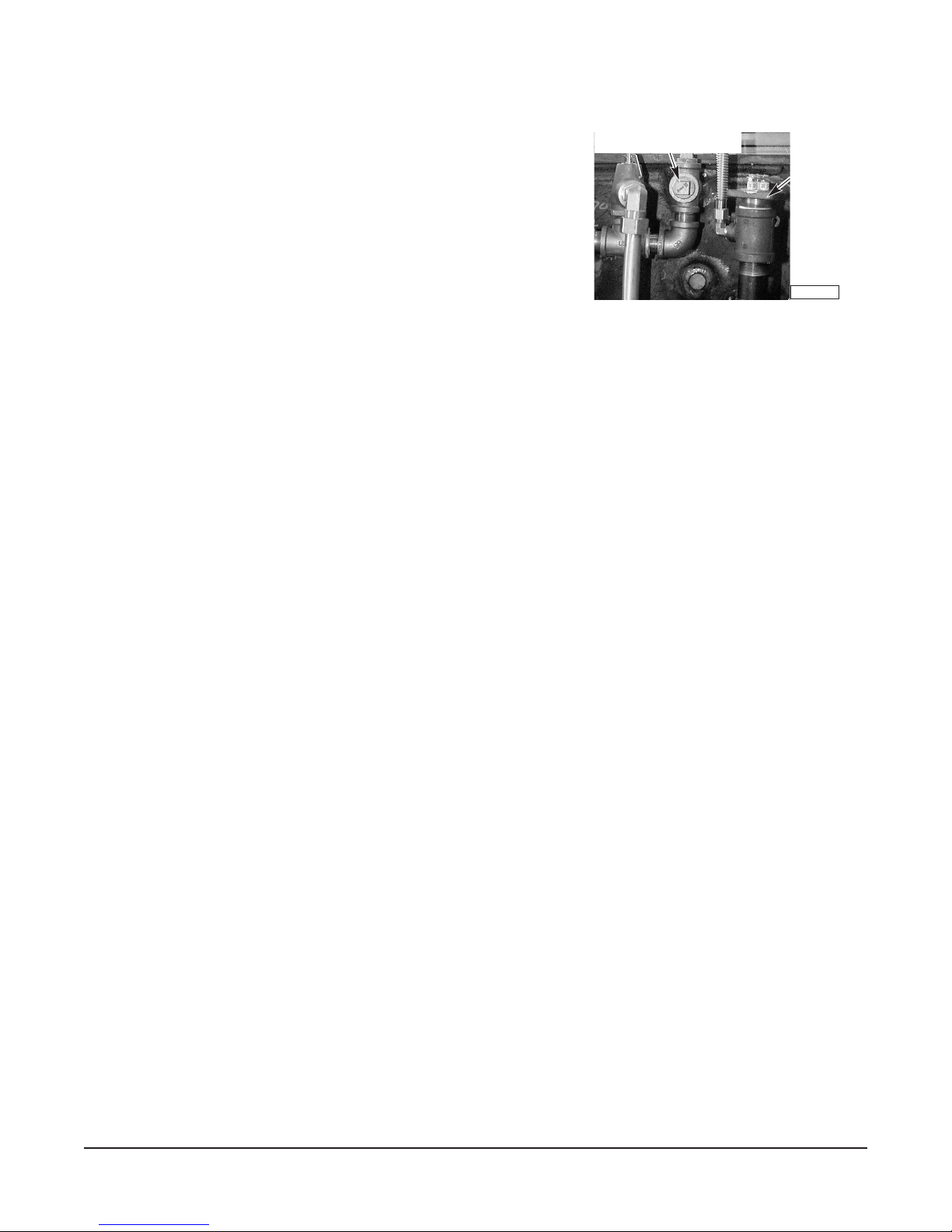
Steam can be supplied to additional steam equipment from
the auxiliary steam port on the boiler, or Steam Line Connection
(Fig. 1). When additional equipment is added, appliance
efficiency will be affected. To be certain that you will be
operating at optimum efficiency, contact the Vulcan-Hart
STEAM LINE CONNECTION
WATER
LEVEL
PROBE
HOUSING
sales representative in your area for steam boiler horsepower
calculations.
The connection point for the steam line to other equipment is
3
a
/
4" NPT tee (female) fitting (1.9 cm) on the left side of the boiler
near the top and towards the rear. Remove the
plug (Fig. 1) (
1.9 cm) and use the piping kit available from
3
/4" NPT pipe
Fig. 1
PL-41764-1
Vulcan-Hart.
SEQUENTIAL STARTUP OF OTHER STEAM COOKING EQUIPMENT CONNECTED TO A BOILER
After the boiler is operating and producing steam, start the equipment that is farthest away until it is
preheated and up to temperature before starting the next piece of equipment. It is recommended that
all kettles be started before any compartment steamers. This will allow the larger equipment or the
equipment with greater steam requirements to be properly warmed up before smaller, nearer units
which require less steam. This will prevent the system from being overwhelmed by initial demand. For
configurations or recommendations, contact your Vulcan-Hart representative.
LOCATION — DIRECT CONNECTED STEAMERS
Position the steamer in its final location.
The recommended clearance for proper operation is 36" (
91.4 cm) at the front. The required clearance
from combustible or non-combustible construction is 0" at the sides and back. The recommended
clearance for service access is 18" (
45.7 cm) at the sides and back. Clearances less than 18" may
require removal of adjacent equipment during servicing at customer's expense.
An exhaust system should be located directly above the steamer to exhaust steam and heat generated
by the steamer.
IMPORTANT: Do not locate the steamer directly over a drain.
DIRECT STEAM CONNECTIONS
Provide dry steam to the inlets. If the steam is heavy with condensate, install a ball float trap before
the pressure regulator valve. To ensure rapid heatup of heavy, cold loads, the steam supply line must
be sized to provide the following:
1. To maintain steam at a pressure of 10 to 12 psi (
2. A minimum flow rate of 40 pounds (
3. A minimum flow rate of 67 pounds (
18.2 kg) of steam per hour per compartment for model VHX24D.
30.4 kg) of steam per hour per compartment for model
68.9 to 82.7 kPa).
VHX24D5.
4. A minimum flow rate of 34 pounds (
steamers.
A pressure-reducing valve is furnished and set at 10 psi (
modules can be interconnected to the steamer. Consult Vulcan-Hart for recommendations.
15.4 kg) of steam per hour per compartment for VHL series
68.9 kPa). Additional steam kettles and kettle
– 10 –
 Loading...