

Page 1
SERVICE MANUAL
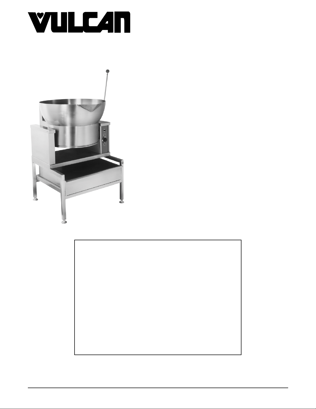
ROUND COUNTER TOP
TILTING BRAISING PANS
(16 GALLON)
GAS AND ELECTRIC
VGCTS16 ML-114827
VECTS16 ML-114825
VGCTS16 SHOWN ON STAND
This Manual is prepared for th e use of trained Vulcan Service
Technicians and should not be used by those not properly
qu alifi ed. If yo u have attend ed a Vulcan Service School for this
product, you may be qualified to perform all the procedures
described in this man ual.
This manual is not intended to be all encompassing. If you have
not attended a Vulcan Service School for this produc t, y ou should
read, in its entirety, th e repair procedure you wish to perform to
determine if you have the necessary tools, instruments a nd s k ills
required to perfo rm t he procedure. Procedures for which you do
not have th e n ecessary tools, instruments and skills should be
performed b y a t rained Vul can Service Technician.
Reproduction or other use of this Manual, without the express
written consent of Vulcan, is prohibited.
- NOTICE -
A product of
Form 24643 (MARCH 1999)
VULCAN-HART LOUISVILLE , KY 40201-0696
Page 2

ROUND TILTING BRAISI NG PANS
g
g
g
g
g
g
g
g
g
g
TABLE OF CONTENTS
GENERAL............................................................................. 3
Introduction ........................................................................ 3
Model Desi
Control Locat ion ................................................................. 3
Specifications ...................................................................... 4
Electric Braisin
Gas Braisin
Tools ............................................................................. 4
REMOVAL AND REPLACEMENT OF PARTS ................................................. 5
Illustr ation - Elec tric Model ............................................................. 5
Illustr ation - Gas Model ............................................................... 6
Thermostat s (Electric M odel) ........................................................... 7
ht and Left Consol e Cover .......................................................... 8
Ri
Bottom Cover ...................................................................... 8
Temperat ur e Controller and P otentiom eter
(Gas Model) .................................................................... 8
Hi Limit Thermostat (Gas Model ) ........................................................ 8
Heater Contactor s ................................................................... 9
Heatin
Pan Assembly ..................................................................... 10
Bearin
Limit Switch (G as Model) ............................................................ 11
Elements ................................................................... 9
s ......................................................................... 11
nations .............................................................. 3
Pan ............................................................. 4
Pan ................................................................ 4
SERVICE PROCEDURES AND ADJUSTMENTS .............................................. 12
Manif old Pressure Adjustment (Gas Model) ............................................... 12
Flam e S ense Probe ( Gas Model) ....................................................... 13
Hot Surf ac e I
(Gas Model) ................................................................... 14
Temperat ur e Controller A nd P otentiom eter Test
(Gas Model) ................................................................... 14
Heatin
(Electr ic Model) ................................................................ 15
ELECTRICAL OPERATION .............................................................. 16
Component Func tion ................................................................ 16
Sequence of O per ation .............................................................. 16
Electric Model ................................................................. 16
Gas Model .................................................................... 17
Schematic Dia
Electric Model ................................................................. 18
Gas Model .................................................................... 19
Diagrams ................................................................... 20
Wi ri n
Electric Model (208/ 240V ) ........................................................ 20
Electric Model (480V) ............................................................ 21
Gas Model .................................................................... 22
TROUBLESHOOTING .................................................................. 23
All Models ........................................................................ 23
Gas Models Only ................................................................... 24
nitor
Elements
rams ................................................................ 18
© VULCAN 1999
Page 2 of 24
Page 3
ROUND TILTING BRAISI NG PANS - GENERA L
g
g
g
g
g
GENERAL
INTRODUCTION
The Vulcan round tilting braising pan (skillet) is a versatile piece of cooking equipment . It can be used to stew,
simm er , sear, pan fry,
is ful ly cooked, the pan c an be tilted usi n
pan is 16
Model Designations
X C T S 16
V
allons (60.6 liters) and can be mounted on a counter top or optional stand.
rill or saute food products under an evenly distributed heating surface. O nc e the product
the handle to empty the product from the pan. The full capac ity of the
16 Gallon Capac ity
Skillet
Tiltin
Counter Top
Heatin
G - Gas
E - Electric
Vulcan
System:
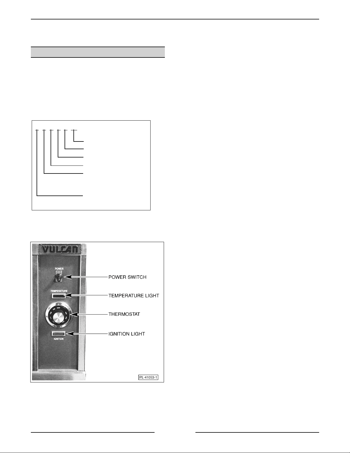
Control Location
Gas Model Shown
Page 3 of 24
Page 4
ROUND TILTING BRAISI NG PANS - GENERA L
g
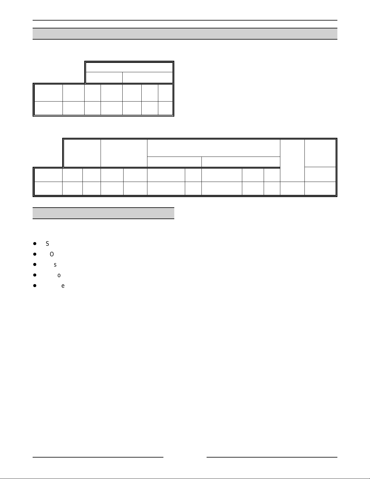
SPECIFICATIONS
Electric Braising Pan
AMPERAGE
1 PHASE 3 PHASE
MODEL
VECTS 16 7.5 36 31.3 20.8 18.1 9.0
Gas Braising Pan
TOTAL
KW
208V 240V 208V 240V 480V
INPUT
BTU/HR
MODEL NAT. PROP. NAT. PROP. RECOMMEND MIN RECOMMEND MIN MAX
VGCTS16 30,000 30,000 3.5 10.0 7.0 5.0 11.0 11.0 14.0 180
MANIFOLD
PRESSURE
(INCHES W.C.)
NATURAL PROPANE
LINE PRESSURE
(INCHES W.C.)
LOAD
(WATTS)
TOOLS
Standard
Standard set of hand tools.
VOM with an AC cur r ent tester (meter sensitivity shoul d be at least 20,000 ohm s per volt c an be used).
Gas leak checkin
Manometer
Temperat ur e meter (ther mocouple ty pe)
equipment .
AMPS
(MAX)
120V
60HZ
1.5
Page 4 of 24
Page 5
ROUND TILTING BRAISING PANS - REMOVAL AND REPLACEMENT OF PART S
REMOVAL AND REPLACEMENT OF PARTS
Refer to the appropriate illustration for component location and identity. Only major com ponents are covered by
a replacem ent procedure.
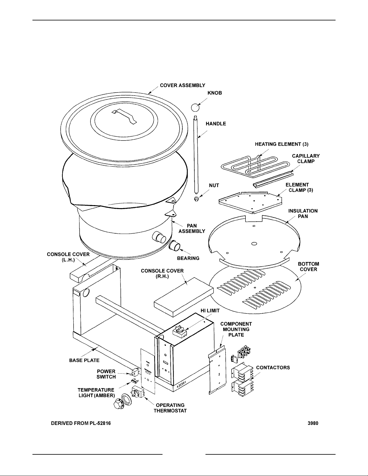
ILLUSTRATION - ELECTRIC MODEL
Page 5 of 24
Page 6
ROUND TILTING BRAISING PANS - REMOVAL AND REPLACEMENT OF PART S
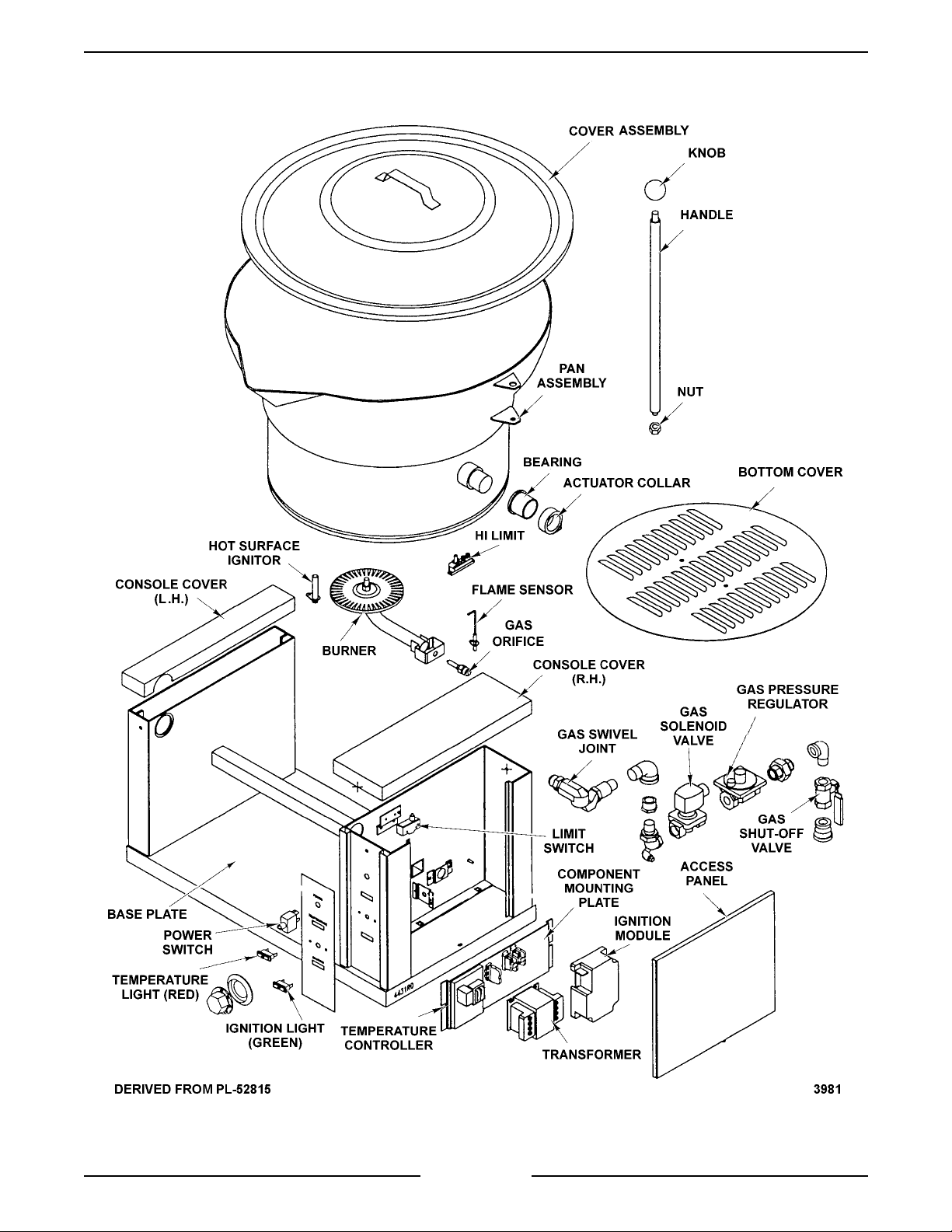
ILLUSTRATION - GAS MODEL
Page 6 of 24
Page 7
ROUND TILTING BRAISING PANS - REMOVAL AND REPLACEMENT OF PART S
g
g
g
g
g
g
g
g
g
g
g
g
g
g
g
g
THERMOSTATS
(Electric Model)
WARNING:
POWER TO T HE MACHINE AT THE MAIN
CIRCUIT BO X. P LA CE A TAG ON THE CIRCUIT
BOX INDICATING THE CIRCUIT IS BEING
SERVICED.
1. Remove ri
“RIGHT AND LE FT CONSOLE COVER”.
A. If replacin
B. If replacin
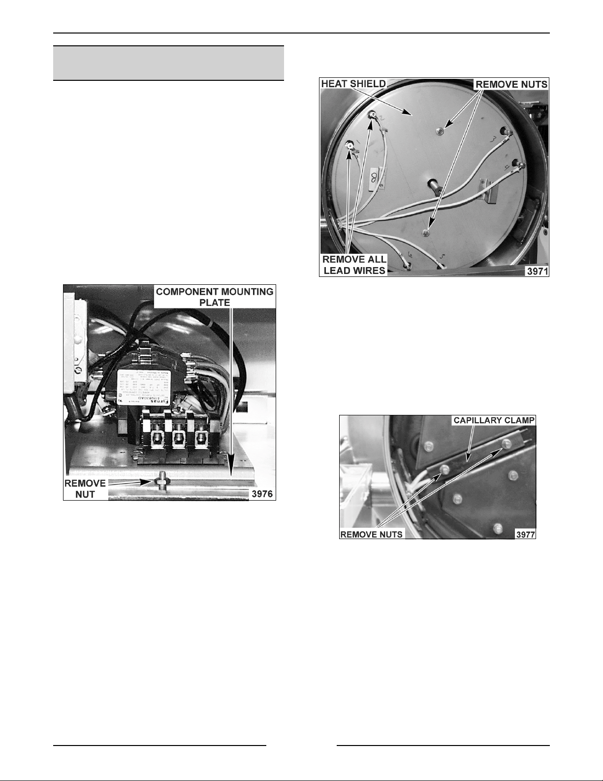
2. Remove component mountin
access to the operatin
nut from threaded stud.
DISCONNECT THE ELECTRICAL
ht console cover as outli ned under
operating thermostat pr oc eed
to step 2.
Hi Limit thermostat proceed to
step 4.
plate to gain
thermostat by r emov in
B. Disconnect heater lead wires and mark
accordin
C. Remove the two nuts from mounting stud
that secure the i nsul ation pan to the
bottom of the brai si n
ly f or pr oper r eplacement.
pan.
A. Grasp plate and pul l upwards while
rotatin
fastener.
3. Pull thermostat knob off from the control panel
and remove mountin
A. Lift thermostat out of contr ol box.
B. Remove lead wires fr om term inals.
4. Remove therm ostat bulb fr om the bottom of
the pan for the thermostat bein
left to right to f r ee it fr om bottom
screws and bezel ring.
replaced.
D. Pull the heater lead wires back throu
openin
the insulation pan to be li fted out.
E. Remove the nuts from the capillary clamp
that secure both ther mostat bulbs to t he
bottom of the brai si n
F. Pull the capillary tube and bulb for the
thermostat bein
the openin
unit.
5. Rever se procedur e to install a new thermostat
and check for pr oper oper ation.
in bearing to allow cl ear anc e for
pan.
replaced, back through
in bearing and remove from
h the
A. Remove bottom c over as outl ined under
“BOTTOM COVER”.
Page 7 of 24
Page 8
ROUND TILTING BRAISING PANS - REMOVAL AND REPLACEMENT OF PART S
g
g
g
g
g
g
g
g
g
g
g
g
RIGHT AND LEFT
CONSOLE COVER
WARNING:
POWER TO T HE MACHINE AT THE MAIN
CIRCUIT BO X. P LA CE A TAG ON THE CIRCUIT
BOX INDICATING THE CIRCUIT IS BEING
SERVICED.
1. Remove screw at the rear of the cover.
2. Lif t up on cover while workin
to free it at the front.
3. Rever se procedur e to install .
DISCONNECT THE ELECTRICAL
it back and forth
BOTTOM COVER
WARNING:
POWER TO T HE MACHINE AT THE MAIN
CIRCUIT BO X. P LA CE A TAG ON THE CIRCUIT
BOX INDICATING THE CIRCUIT IS BEING
SERVICED.
DISCONNECT THE ELECTRICAL
6. Disconnect the lead wires from the temper ature
controller board.
7. Remove the mountin
8. Rever se procedur e to install a new temperature
controller and check f or pr oper oper ation.
screws.
HI LIMIT THERMOSTAT
(Gas Model)
WARNING:
POWER TO T HE MACHINE AT THE MAIN
CIRCUIT BO X. P LA CE A TAG ON THE CIRCUIT
BOX INDICATING THE CIRCUIT IS BEING
SERVICED.
WARNING:
BEFORE SERVICING THE UNIT.
1. Remove the bottom cover as outlined under
“BOTTOM COVER”.
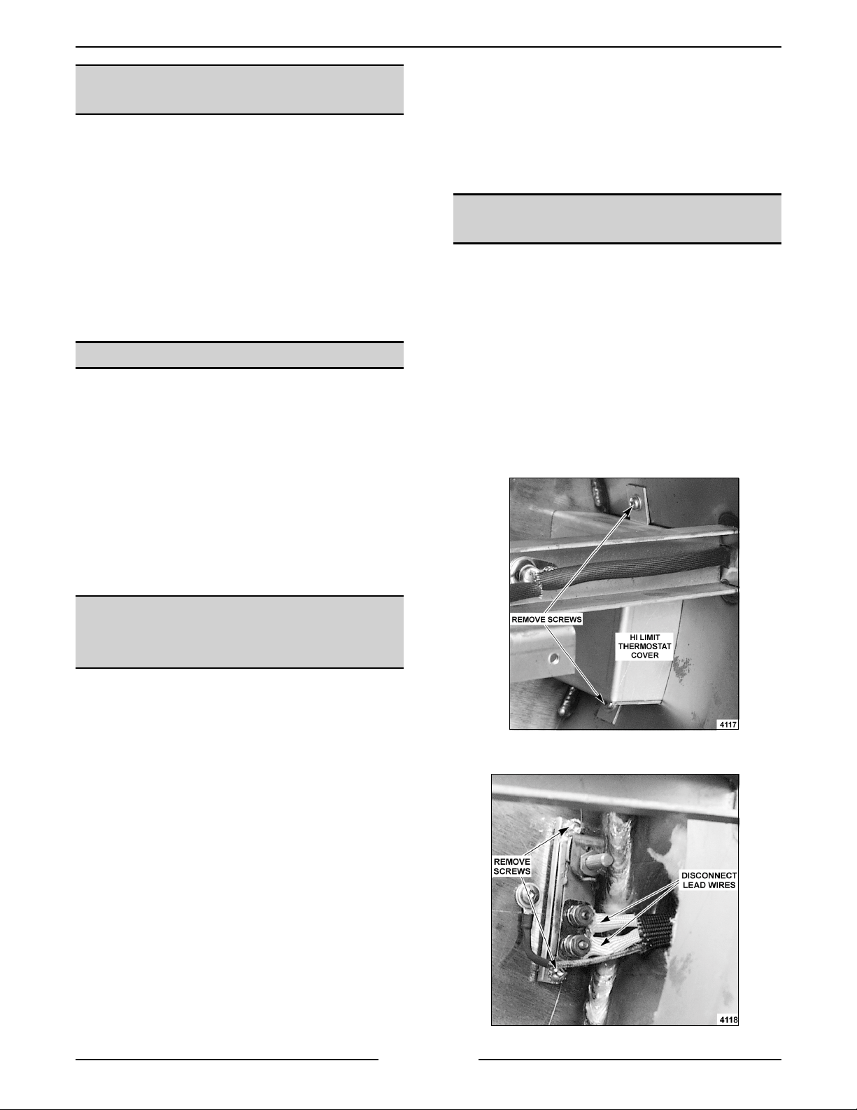
2. Remove the screws securin
box to the under si de of the pan and lift off.
DISCONNECT THE ELECTRICAL
SHUT OFF THE GAS SUPPLY
the heat shield
1. Til t braisin
on the stop bar.
2. Remove screw(s) holdin
3. Rever se procedur e to install .
pan forward unti l it comes to rest
the round cover.
TEMPERATURE CONTROLLER
AND POTENT IOMETER
(GAS MODEL)
WARNING:
POWER TO T HE MACHINE AT THE MAIN
CIRCUIT BO X. P LA CE A TAG ON THE CIRCUIT
BOX INDICATING THE CIRCUIT IS BEING
SERVICED.
WARNING:
BEFORE SERVICING THE UNIT.
1. Remove ri
“RIGHT AND LE FT CONSOLE COVER”.
2. Pull out the ri
the compartment cont r ols.
DISCONNECT THE ELECTRICAL
SHUT OFF THE GAS SUPPLY
ht console cover as outli ned under
ht side access panel to expose
3. Disconnect the lead wires from the hi
h limit.
3. Loosen the two set screws from the
temperat ur e dial and pull the dial off.
4. Remove the bezel r in
mounti n
5. Remove the nut securi n
the mountin
screws.
bracket.
and potentiometer
the potenti ometer to
Page 8 of 24
Page 9

ROUND TILTING BRAISING PANS - REMOVAL AND REPLACEMENT OF PART S
g
g
g
g
g
g
g
g
g
g
g
g
g
g
4. Remove the screws securing the high limit to
the underside of the pan.
5. Rever se procedur e to install a new hi limit and
check unit for proper operat ion.
HEATER CONTACTORS
WARNING:
POWER TO T HE MACHINE AT THE MAIN
CIRCUIT BO X. P LA CE A TAG ON THE CIRCUIT
BOX INDICATING THE CIRCUIT IS BEING
SERVICED.
1. Remove ri
“RIGHT AND LE FT CONSOLE COVER”.
2. Remove component mountin
access to contactors by removin
threaded stud.
DISCONNECT THE ELECTRICAL
ht console cover as outli ned under
plate to gain
nut from
HEATING ELEMENTS
WARNING:
POWER TO T HE MACHINE AT THE MAIN
CIRCUIT BO X. P LA CE A TAG ON THE CIRCUIT
BOX INDICATING THE CIRCUIT IS BEING
SERVICED.
1. Remove bottom cover as outlined under
“BOTTOM COVER”.
2. Disconnect heater lead wires and mark
accordin
DISCONNECT THE ELECTRICAL
ly f or pr oper r eplacement.
A. Grasp plate and pul l upwards while
rotatin
fastener.
3. Remove lead wires f r om contactor bein
replaced.
4. Remove contactor mountin
5. Rever se procedur e to install a new contac tor
and check for pr oper oper ation.
left to right to f r ee it fr om bottom
screws.
3. Remove the two nuts fr om mountin
secure the insulation pan to the bott om of t he
braisin
4. Push the heater lead wir es back throu
openin
insulati on pan to be lifted out.
5. Remove the nuts securin
to the braisi n
bein
pan.
in bearing to allow cl ear anc e for the
the elem ent clamp
pan bottom for the el ement
replaced.
stud that
h the
6. Replace with a new element and reverse
procedure to install.
Page 9 of 24
Page 10

ROUND TILTING BRAISING PANS - REMOVAL AND REPLACEMENT OF PART S
g
g
g
g
g
g
g
g g
g
g
g
g
PAN ASSEMBLY
WARNING:
POWER TO T HE MACHINE AT THE MAIN
CIRCUIT BO X. P LA CE A TAG ON THE CIRCUIT
BOX INDICATING THE CIRCUIT IS BEING
SERVICED.
1. Remove ri
outlined under “ RIGHT AND LEFT CONSOLE
COVER”.
2. Remove bottom cover as outlined under
“BOTTOM COVER”.
3. Electr ic model only - for
step 4.
A. Remove the heater l ead wir es and heatin
B. Proceed to step 5.
4. Gas model only.
WARNING:
BEFORE SERVICING THE UNIT.
WARNING:
DURING SERVI CING MUST BE CHE CK E D FOR
LEAKS. CHECK WITH A SOAP AND WATER
SOLUTION (BUBBLES). DO NOT USE AN OPEN
FLAME.
DISCONNECT THE ELECTRICAL
ht and left console cover as
as model proceed t o
element s as outl ined under “HEATI NG
ELEMENTS”.
SHUT OFF THE GAS SUPPLY
ALL GAS JOINTS DISTURBED
B. Remove those same components from the
underside of pan and set t hem aside for
re-installin
assembly.
C. Loosen the nut at the top of the burner that
secures the burner to bracket and r emov e.
D. Unscrew the
E. Separate the brass union j ust below the
as swivel connector and unscrew the
threaded end of the connector from the
pan sleeve.
F. Loosen the set screw at the top of the
actuator collar and rem ove the collar.
on replacem ent pan
as orifice and remove.
A. Disconnect the component lead wires for
the HSI, F S P , HL AND TC fr om the
terminal strip located in the left hand
console and pull the insulati on sl eeve and
wires throu
h opening in bearing.
G. Disconnect the incomin
Remove the
separatin
assembly line and removin
securin
as line assembly by
the second union in t he gas
the mounting bracket.
as supply line.
the nuts
Page 10 of 24
Page 11

ROUND TILTING BRAISING PANS - REMOVAL AND REPLACEMENT OF PART S
g
g
g
g
g
g
g
g
g
g
g
g
g
g
g
g
5. Unbolt the br aising pan from the mountin
surface or stand.
6. Lay the braisi n
four base plat e mountin
7. Remove the nuts and carria
side to separate the base plat e from the ri
side support member.
8. Gently str ike the inner si de of the support
member by hand or r ubber mallet to dislod
the pan assembly sleeve f r om the bearin
Before t he sl eeve separates f r om the bearin
rasp the pan for support.
pan on its back to expose the
nuts and bolts.
e bolts on the right
BEARINGS
WARNING: DISCONNECT THE ELECTRICAL
POWER TO T HE MACHINE AT THE MAIN
ht
CIRCUIT BO X. P LA CE A TAG ON THE CIRCUIT
BOX INDICATING THE CIRCUIT IS BEING
SERVICED.
1. Remove the pan assembly as outlined under
“PAN ASSEMBLY”.
2. Remove the bearin
support mem ber .
NOTE: CHECK CONDITION OF BEARING ON
OPPOSITE SIDE AND REPLACE IF NECESSARY.
3. Replace with a new bearin
procedure to install.
to be replaced from t he
and rever se
LIMIT SWITCH (Gas Model)
e
.
,
WARNING: DISCONNECT THE ELECTRICAL
POWER TO T HE MACHINE AT THE MAIN
CIRCUIT BO X. P LA CE A TAG ON THE CIRCUIT
BOX INDICATING THE CIRCUIT IS BEING
SERVICED.
9. Grasp the pan f irml y and then pull i t away from
the left side bearin
NOTE: CHECK CONDITION OF BOTH BEARINGS
WHILE PAN IS OUT AND REPLACE IF
NECESSARY.
10. Replace with a new pan and reverse procedure
to install.
.
1. Remove ri
“RIGHT AND LE FT CONSOLE COVER”.
2. Pull out the ri
the compartment cont r ols.
3. Disconnect the lead wires from the switch.
4. Til t braisin
on the stop bar.
5. Remove the screws securin
bracket.
6. Rever se procedur e to install and c hec k for
proper operation.
ht console cover as outli ned under
ht side access panel to expose
pan forward unti l it comes to rest
the switch to the
Page 11 of 24
Page 12

ROUND TILTING BRAISI NG PANS - SERVI CE P ROCEDURES AND ADJUST M E NTS
g
g
g
g
g
g
g
g
SERVICE PROCEDURES AND ADJUSTMENTS
WARNING: CERTAIN PROCEDURES IN THIS SECTION REQUIRE ELECTRICAL TEST OR
MEASUREMENTS WHILE POWER IS APPLIED TO THE MACHINE. EXERCI SE EXTREME CAUTION AT ALL
TIMES. IF TEST POI NTS ARE NOT EASI LY ACCESSIBLE, DISCONNECT POWER, ATTACH TEST
EQUIPMENT AND REAPPLY POWER TO TEST.
MANIFOLD PRESSURE
ADJUSTMENT (Gas Model)
WARNING: DISCONNECT THE ELECTRICAL
POWER TO T HE MACHINE AT THE MAIN
CIRCUIT BO X. P LA CE A TAG ON THE CIRCUIT
BOX INDICATING THE CIRCUIT IS BEING
SERVICED.
WARNING: SHUT OFF THE GAS SUPPLY
BEFORE SERVICING THE UNIT.
1. Remove the ri
outlined under " RIGHT AND LEFT CONSOLE
COVER".
2. Pull out the ri
the compartment cont r ols.
3. Remove the 1/4" NPT pipe plu
manifold and att ac h a manometer .
4. Remove the adjustment screw cap to access
the pressure adjustment screw.
ht side console cover as
ht side access panel to expose
from the
6. Aft er the burner li
outline below:
A. To increase pressure, turn the screw
clockwise
B. To decrease pressure, turn the screw
countercloc k wise
GAS TYPE MANIFOLD
NATURAL 3.5 7.0 5.0
PROPANE 10.0 11.0 11.0
* If t he incomi ng line pressure is less than the
minimum stated, then the manifold pressure can not
be set correctly.
7. Once the corr ec t pressure has been set, turn
the power switch “OFF”, replace the
adjustment screw cap and manifold pipe plu
8. Check unit for proper operat ion.
hts, set the pressure as
.
.
PRESSURE READINGS
(INCHES W.C.)
LINE
RECOMMENDED MIN MAX
14
.
5. Plu
NOTE: Accurate
be made with the
in the unit, turn “on” t he gas, set the power
switch to “on” and set the t her mostat.
as pressure adjustments can only
as “ON” and the burner l it.
Page 12 of 24
Page 13

ROUND TILTING BRAISI NG PANS - SERVI CE P ROCEDURES AND ADJUST M E NTS
g
g
g
g
g
g
g
g
g
g
g
g
g
g
g
FLAME SENSE PROBE
(Gas Model)
WARNING:
POW E R TO BE APPLIED TO THE UNIT DURING
THE TEST. USE EXTREME CAUTION AT ALL
TIMES.
1. Assure proper
the v alue of i nc omin
A. Check the f lame sense probe mi c r o
THE FOLLOWI NG ST EPS REQUIRE
round, correct polarity and that
voltage is correct.
amp
current by di sconnectin
probe lead f r om the terminal strip and
placin
a V-O-M in series.
the fame sense
2) I f the readi n
amps, turn t her mostat and power
switch OFF. Check the flame sense
probe for cor r osi on or
and for l oose or dirty connections on
the term inal strips under t he r i
left console covers. If F SP is dirty,
clean with sandpaper and repeat step
1C. Also, Check the flame sense
probe position as outlined below in
step two. Lastly, visually inspect the
burner flame. If flame appears low or
not burnin
as manifold pressure as outlined
under “MANIFOLD PRES S URE
ADJUSTMENT (GAS MODELS). If
pressure is not set correctly then
adjust and check for proper operation.
2. Perfor m a v isual check to det er mine if the
flame sense probe is in the upper port ion of
flame. If the probe is bent or not in the upper
portion of the flame then chec k ali
adjust as necessary.
A. The center l ine of the pr obe shoul d be
approximately 2 9/16 inches from the
underside of t he pan and 4 inches up from
the center l ine of the bur ner .
is less than 0.5 micro
rease build up
correctl y , then check the
nment and
ht and
B. Switch the meter leads to measure current
and set the meter to read mic r o amps DC.
C. O pen the
and set thermostat .
D. O bserve meter readin
1) I f the readi n
as valve, t ur n power switch O N
.
is greater than 0.5
micr o amps DC then the problem is
not with the FS P . Replace i
control module and check for proper
operation.
nition
B. If no adjustments can be m ade to the
probe to correct its ali
and check unit for proper operat ion.
nment then r eplace
Page 13 of 24
Page 14

ROUND TILTING BRAISI NG PANS - SERVI CE P ROCEDURES AND ADJUST M E NTS
g
g
g
g
g
g
g
g
g
g
g
g
g
g
g
g
g
g
g
g
HOT SURFACE IGNITOR
(GAS MODEL)
1. Check to see if hot surface ignitor i s operat in
during
A. Visual verification - HSI should be heatin
B. Volta
WARNING:
POWER TO T HE MACHINE AT THE MAIN
CIRCUIT BO X. P LA CE A TAG ON THE CIRCUIT
BOX INDICATING THE CIRCUIT IS BEING
SERVICED.
ignition trial
up “glowing brightly” to ignite gas.
e verification - check for 24VAC to
HSI termination on the ed
round.
DISCONNECT THE ELECTRICAL
by:
e connector to
TEMPERATURE CONTROLLER
AND POTENT IOMETER TEST
(GAS MODEL)
WARNING:
POW E R TO BE APPLIED TO THE UNIT DURING
THE TEST. USE EXTREME CAUTION AT ALL
TIMES.
Temperature Controller
1. Assure a proper
that the value of incom in
2. Turn the
set the therm ostat to call for heat. The braisin
pan must also be down to close l imit switch.
3. Verify the temperature controller is receivin
power (120VAC) across L1 & L2. Once the
relay contac ts close, the temperature li
the front control panel will illuminate and the
step down transformer r ec eives power.
A. If controller output remains for
B. If t he c ontroller r emains ener
THE FOLLOWI NG ST EPS REQUIRE
round, correct polarity and
voltage is correct.
as supply on, power switch ON and
ht on
approximately 20 seconds then drops off,
an open thermocouple condition may
exist. Replace the thermocouple and
check for pr oper oper ation.
ized but
burner does not come on, veri fy the relay
contacts (N.O.) are openin
when power to the controll er is removed
and applied. Chec k volta
N.O. and L2.
1) I f relay is functionin
the problem is not with the controller.
See Troubleshootin
2) I f relay is not funct ionin
then replace controller and c hec k
proper operation.
and closin
e out between
properly then
section.
properly
2. Unplu
module and chec k r esi stanc e between HSI lead
wire and
the edge connector from the ignition
round.
HSI
CONDIT ION
COLD 1 - 4
HOT 8 - 10
RESISTANCE
(approx. Ohms)
Page 14 of 24
Page 15

ROUND TILTING BRAISI NG PANS - SERVI CE P ROCEDURES AND ADJUST M E NTS
g
g
g
g
g
g
g
g
g
g
g
g
g
g
g
g
g
g
g
g
g
Potenti ometer
Perform the f ollowin
potentiometer is functioni n
the temper ature settin
connected from TC (-) to the wiper (red) on the
potentiometer will read a v olta
the set point t emperature. E x. If the set point is
300°F the DC volta
be approximately 1.49 volts.
1. If the thermocouple condition has not
verifi ed as descri bed in step 3A abov e, place a
jumper across TC (-) and TC (+). If the
thermocouple condition has been veri fied,
proceed to step 2.
NOTE: Remov e jumper when test is
completed.
2. Connect the bl ac k meter lead of a V-O-M to the
TC (-) on the temperature controller.
3. Connect the red meter lead of a V-O-M to the
red wire (wiper arm ) on the potentiometer.
4. Turn the power switch on and set the
temperat ur e dial to 100°F. Increase set point to
200°F, 300°F , 400°F and 450 °F while
monit or in
points. Com par e the meter readin
chart below.
test procedure to verify the
properly and to c onfirm
of the dial. A V-O-M
e that corresponds to
e measured at the wiper shoul d
been
the v oltage change between dial set
s to the
HEATING ELEMENTS
(ELECTRIC MODEL)
WARNING: THE FOLLOW I NG ST EPS REQUIRE
POW E R TO BE APPLIED TO THE UNIT DURING
THE TEST. USE EXTREME CAUTION AT ALL
TIMES.
1. Measure the volta
terminals and ver ify it a
e.
volta
A. If volta
the problem.
2. If volta
throu
current draw is correct then heatin
ok. See table below for proper values.
A. If cur r ent draw is not correct t hen, replace
3. Check for pr oper oper ation.
VOLTAGE
208 7.5 36.1 20.9 17.4
e is correct, check current draw (amps)
h the heating element lead wires. If
heatin
element .
TOTAL
KW
e at the heati ng element
ainst the data plate
e is incorrect, find the source of
element is
AMPERAGE
PER LINE
1 PH 3 PH
OHMS PER
ELEMENT
TEMPERATURE
SETTI NG (°F)
100 0.38
200 0.93
300 1.49
400 2.0
450 2.3
A. If the volta
those listed i n the table and the increase in
e was smooth without drops or
volta
spikes then the potentiometer is
functionin
B. If the volta
with those listed in the table or the
increase in volta
with drops or spikes then the
potentiometer is not functionin
Replace the temperature cont r oller and
potentiometer assembly and c hec k unit for
proper operation.
properly.
APPROXIMATE
DC VOLTAGE
e measurement s agree with
e measurement s do not agree
e was not smooth but
240 7.5 31.3 18.1 23.1
480 7.5 9.0 30.6
NOTE: V alues in the tabl e ar e nominal. Tolerance is
+5/-10 %.
properly.
Page 15 of 24
Page 16

ROUND TILTING BRAISI NG PANS - ELECTRICAL OPERATION
g
g
g
g
g
g
g
g
g
g
g
g
g
g
g
g
g
g
g
g
g
g
g
g
g
g
g
g
g
g
g
g
g
g
g
g
g
ELECTRICAL OPERATION
COMPONENT FUNCTION
Heater Contacto rs ........ Controls power to heati n
Heating Elements (3) ..... Heat the braisin
Transformer ............ Provides 24VAC power to i
Ignition Module ......... Controls and moni tors
monit or s flame pr esence t hr ou
second i
Temperature Light ....... Indicates the power switch is on and a t emperature settin
when set point temper ature is reached and will come back on when temperature
drops below set point.
Ignition Light ........... Indicates
FSP (Fl ame S ense Probe) . . Supplies a current si
flame. (
HSI (Hot Surface Igniter) . . When I
temperat ur es to i
Power Switch ........... Controls electr ical power to the control cir c uit.
Limit Switch ............. Removes electrical power to the temperature control board when the pan is
tilted. (
Gas Solenoid Valve ....... Allows
(
as models only)
High Limit Thermostat .... Will not allow heater contac tor (on electr ic model s) or i
models) to ener
Control Thermostat ....... Cycles power to heat er c ontactors to maintain the set point tem per ature.
(electric model s onl y )
Temperature Controller .... Cycles power to the i
temperat ur e. (
nition trial t ime and powers gas solenoid v alve. (gas models only)
as models only)
nition module applies power, the HSI element heats up to very high
as models only)
as flow to burner when solenoid is energized. A normally c losed val ve.
pan cooking surface. (electric models only)
as burner is on. (gas models only)
nite the gas. (gas models only)
ize if the pan surfac e temperature goes beyond 536°F (280°C).
as models only)
element s. ( electric models only)
nition c ontrol module and HSI. (gas models only)
as heating. Appli es power to HSI for burner ignition,
h FSP, cont r ols 5 second purge tim e and 8.5
dialed. Light goes out
nal back to t he ignition module indicating the presence of a
nition module (on gas
nition c ontrol module to maintain the set point
SEQUENCE OF OPERATION
Electric Mo del
1. Conditi ons.
A. Braisin
and is properly
B. Power switch OFF.
C. Hi
D. Cont r ol Thermostat dial OFF.
E. Temperat ur e li
2. Power switch turned ON.
A. L1 volta
thermostat c ontacts (N.C.) t o one si de of
the control thermostat.
B. L3 volta
3. Turn thermostat (potentiometer) dial unti l a call
for heat is made.
1) T emperature l i
2) L1 volt a
Pan connected to cor r ec t voltage
rounded.
h limit thermostat contacts closed.
ht OFF.
e supplied through high limit
e to one side of c ontactor coils.
ht comes on.
e is supplied to t he other
side of cont ac tor coils. Coils are
ener
ized and contacts close.
3) Heat in
and the cookin
heat up.
4. Control t her mostat reaches set point
temperat ur e and c ontacts (N.O.) open.
A. Temperat ur e li
B. L1 volta
contactor coils. Coils are de-ener
contacts open.
C. Heat in
allowin
5. Control t her mostat temperature drops below set
point and contac ts (N.O.) close.
A. Cookin
maintained by the heaters cyclin
control t her mostat unti l the thermostat dial
is turned to the OFF position or the power
switch is turned OFF.
element s are t hen energized
surface begins to
ht goes out.
e is removed fr om one side of
ized and
element s are t hen de- energized
the cooking surface to cool.
surface temperature is
with the
Page 16 of 24
Page 17

ROUND TILTING BRAISI NG PANS - ELECTRICAL OPERATION
g
g
g
g
g
g
g
g
g
g
g
g
g
g
g
g
g
g
g
g
g
g
g
g
g
g
g
g
g
g
g
g
g
Gas Model
1. Conditions.
A. Unit connect ed to correct volta
is correct and is properly
e, polari ty
rounded.
B. Power switch OFF.
C. G as supply valve is ON.
D. Limit switc h c losed (pan down).
E. Thermostat (potentiometer) dial OFF ( 0
ohms between wiper arm t er minal ( r ed
lead) & one side of the coil (white lead)
CW rotation).
F. T emperature cont r oller internal relay
contacts (N.O.) are open.
G. Temperat ur e li
H. I
I. Hi
nition light off.
h limit thermostat contacts (N.C.)
ht off.
closed.
2. Power switch ON.
A. Temperat ur e c ontroller r ec eives power
from L1 (120VAC) and NEUTRAL and is
ized through L1 & L2 terminals on
ener
controller.
B. L1 (120VAC) to the c ommon side of
internal r elay contacts.
C. NEUTRAL to one side of the temperat ur e
ht and step down transformer (120VAC
li
to 24VAC).
3. Turn thermostat (potentiometer) dial unti l a call
for heat is made.
3) When burner lights, flame sense
probe detects f lame, HSI de-
izes aft er an 8.5 second ignition
ener
trial time,
open and heatin
4) I f burner flame is not
nition trial t ime elapses, then the
i
nition c ontrol module locks out
i
as solenoid v alve stay s
begins.
detected after
power to the gas solenoid v alve. The
module remains locked out until the
thermostat ( potentiom eter) dial is
turned to OFF then back t o a set
point temperature or the power switch
is turned OFF then back ON a
ain.
5. Temperature controller reaches set point
temperat ur e.
A. Internal r elay on temper ature controller is
de-ener
B. Temperat ur e li
C. Power i s removed from the i
ized and the cont ac ts open.
ht goes out.
nition c ontrol
module.
1) G as solenoid valve closes.
2) Bur ner shuts off.
nition light goes out.
3) I
6. Temperature controller drops below set point.
A. Cookin
maint ained by the
surface temperature is
as burner cycli ng with
the temper ature controller until the
potentiometer dial is turned to the OFF
position or t he power switch is turned OFF.
A. Internal r elay on temper ature controller is
ized and the (N.O.) contacts close.
ener
B. Power from L1 ( 120V A C) is then supplied
to the other side of the temperature li
and the step down transformer (120VAC to
24VAC).
1) T emperature l i
ht comes on and the
step down transformer is ener
4. I
nition module is energized (24VAC) through
the hi
A. I
h limit (N.C.) contacts and ground.
nition trial cycle begins.
1) Module delays ener
second pur
residual
e time to allow any
as to dissipate. After purge
tim e elapses, HSI be
izing HSI for a 5
ins a 3 second
heat up time.
2) After HSI heat up tim e elapses, the
as solenoid v alve opens to suppl y
as to the hot ignitor and the ignition
ht comes on.
li
ht
ized.
Page 17 of 24
Page 18

Electric Mo del
ROUND TILTING BRAISI NG PANS - ELECTRICAL OPERATION
SCHEMATIC DIAGRAMS
Page 18 of 24
Page 19

Gas Model
ROUND TILTING BRAISI NG PANS - ELECTRICAL OPERATION
Page 19 of 24
Page 20

ROUND TILTING BRAISI NG PANS - ELECTRICAL OPERATION
Electric Mo del (208/240V)
WIRING DIAGRAMS
Page 20 of 24
Page 21

Electric Mo del (480V)
ROUND TILTING BRAISI NG PANS - ELECTRICAL OPERATION
Page 21 of 24
Page 22

Gas Model
ROUND TILTING BRAISI NG PANS - ELECTRICAL OPERATION
Page 22 of 24
Page 23

ROUND TILTING BRAISI NG PANS - TROUB LE S HOOTING
g
g
g
g
g
g
g
g
TROUBLESHOOTING
ALL MODELS
WARNING: CERTAIN PROCEDURES IN THIS SECTION REQUIRE ELECTRICAL TESTS OR
MEASUREMENTS WHILE POWER IS APPLIED TO THE MACHINE. EXERCI SE EXTREME CAUTION AT ALL
TIMES. IF TEST POI NTS ARE NOT EASI LY ACCESSIBLE, DISCONNECT POWER, ATTACH TEST
EQUIPMENT AND REAPPLY POWER TO TEST.
SYMPTOM POSSIBLE CAUSES
Unit will not heat (temperat ur e li
Pan dif ficult to tilt. 1. Dirt in oilite bearin
Cookin
temperat ur e incorrect. 1. Thermoc ouple not secured properly to bottom of pan.
ht off). 1. Check incoming voltage.
2. Control t her mostat not tur ned on or r emains open.
3. Power switch malfuncti on.
4. Hi
5. Heatin
6. Heater contactor(s) malfuncti on ( electric model).
NOTE: Never
problems with tiltin
lubrication.
2. Thermoc ouple lead wire(s) pulled loose from connecti on or
h limit thermostat open.
element inoperative (elec tric m odel).
UNDER REMOVAL AND REPLACEMENT OF PARTS”.
rease or oil the pivot bearings as this may cause
. Bearings are oilite and never requi r e
dama
ed.
s causing it to bind. See “BEARINGS
Page 23 of 24
Page 24

ROUND TILTING BRAISI NG PANS - TROUB LE S HOOTING
g
g
g
g g
g
g
g
g
g
g
g
g
GAS MODELS ONLY
SYMPTOM POSSIBLE CAUSES
Burner won’t li
Burner won’t stay lit. 1. Gas pressure low. See “MANIFOLD PRESSURE
ht. 1. Gas not on.
2. Pan not down to close limit switch.
3. Unit not pr oper ly
power is incorrect.
4. Low incomi n
5. Gas solenoid valve mal functi on.
6. HSI not operat in
MODEL)” in “SERVICE PROCEDURES AND
ADJUSTMENTS”.
7. I
nition module not rec eiving power.
A. Check transform er for 24VAC output to modul e.
B. Hi
h limit thermostat rem ains open.
C. Temperatur e c ontroller or potentiom eter malfuncti on.
See “TEMPERATURE CONTROLLER AND
POTENTIOMETER (GAS MODEL)” in “SERVICE
PROCEDURES AND ADJUSTMENTS”.
8. I
nition module m alfunct ion.
ADJUSTMENT (GAS)” in “SERVICE PROCEDURES AND
ADJUSTMENTS”.
2. Check position of flame sense probe. See “FLAME SENSE
PROBE (GAS MODELS)” in SERVICE PROCEDURES
AND ADJUSTMENTS”.
3. Flame sense probe malf unc tion.
4. I
nition module m alfunct ion.
5. Check
as orifice for obstruc tion.
rounded and/or polarity of incomi n
as pressure.
. See “HOT SURFACE IGNITOR (GAS
HSI heats up but burner will not li
Form 24643 (MARCH 1999) Printed in U.S.A.
ht. 1. Gas supply is off.
2. Gas solenoid valve mal functi on.
3. I
nition module m alfunct ion.
 Loading...