

Page 1
INSTALLATION, OPERATING,
SERVICE AND PARTS MANUAL FOR
DIRECT STEAM FLOOR MOUNTED
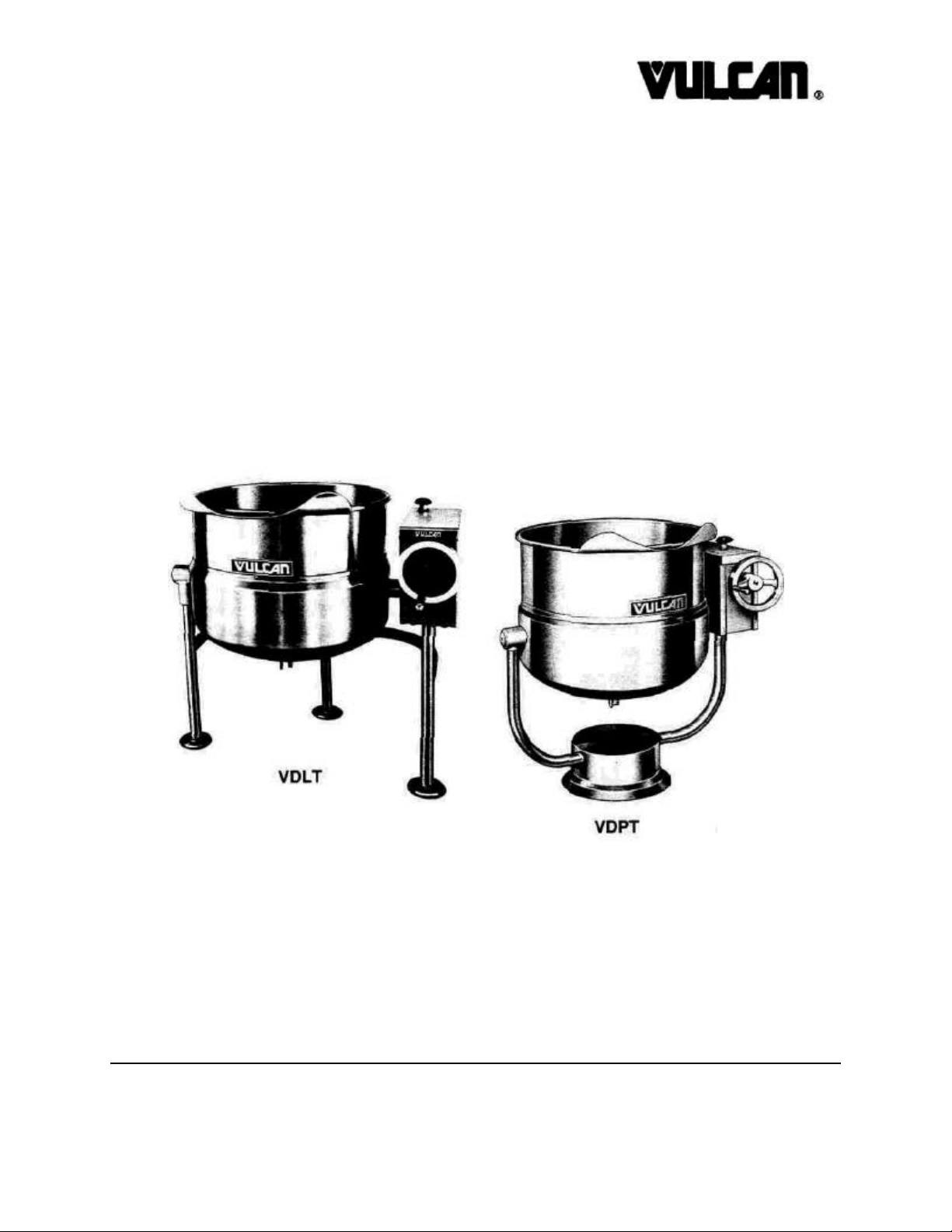
TILTING 2/3 JACKETED KETTLES
SERIES: VDLT&VDPT
Vulcan service agencies are located throughout the
United States. For location and phone
number of one near you, call your local Vulcan
dealer.
VULCAN-HART CORPORATION, P.O. BOX 696, LOUISVILLE, KY 40201-0696, TEL. (502) 778-2791
FORM 30015(2-90)
Page 2

IMPORTANT
OPERATING, INSTALLING AND SERVICE PERSONNEL
The operating information on this equipment has been prepared for use by qualified and/or
authorized operating personnel.
All installation and service on this equipment is to be performed by qualified, certified, licensed and/
or authorized installation or service personnel, with the exception of any part marked with a D in front
of the part number.
To obtain the name and location of an authorized Vulcan service agency, contact your Food Service
Equipment dealer.
DEFINITIONS
QUALIFIED AND/OR AUTHORIZED OPERATING PERSONNEL
Qualified or authorized operating personnel are those who have carefully read the information in this
manual and are familiar with the equipment's functions or have had previous experience with the
operation of the equipment covered in this manual.
1. For the installation of gas piping from the outlet side of the gas meter, or the service regulator
when the meter is not provided, and the connection and installation of the gas appliance,
qualified installation personnel must be experienced in such work, be familiar with all precautions
required, and have complied with all requirements of state or local authorities having jurisdiction.
In the absence of local codes, installation must comply with National Fuel Gas Code ANSI
Z223.1 latest edition.
2. For the installation of electrical wiring from the electric meter, main control box or service outlet
to the electric appliance, qualified installation personnel must be experienced in such work, be
familiar with all precautions required, and have complied with all requirements of state or local
authorities having jurisdiction. In the absence of local codes, installation must comply with the
National Electrical Code ANSI NFPA No. 70 latest edition.
3. For the installation of steam piping from the source of supply to the service inlet of the appliance,
qualified installation personnel must be experienced in such work, be familiar with all precautions
required, and have complied with all requirements of state or local authorities having jurisdiction.
QUALIFIED SERVICE PERSONNEL
Qualified service personnel are those who are familiar with this equipment who have been endorsed
by our company. All authorized service personnel are required to be equipped with a complete set of
service and parts manuals and stock a minimum amount of parts for this equipment.
SHIPPING DAMAGE CLAIM PROCEDURE
For your protection, please note that equipment in this shipment was carefully inspected and packed
by skilled personnel before leaving the factory. The transportation company assumes full responsibility for safe delivery upon acceptance of this shipment.
If shipment arrives damaged:
1. VISIBLE LOSS OR DAMAGE - Be certain this is noted on freight bill or express receipt and
signed by person making delivery.
2. FILE CLAIM FOR DAMAGES IMMEDIATELY - Regardless of extent of damage.
3. CONCEALED LOSS OR DAMAGE- If damage is unnoticed until merchandise is unpacked,
notify transportation company or carrier immediately, and file "concealed damage" claim with
them. This must be done within fifteen (15) days of the date the delivery is made to you. Be sure
to retain container for inspection.
We cannot assume responsibility for damage of loss incurred in transit. We will, however, be glad to
furnish you with necessary documents to support your claim.
PLEASE RETAIN THIS MANUAL FOR FUTURE REFERENCE
2
Page 3

INDEX
Your Vulcan Steam Jacketed Tilting Kettle is produced
with quality workmanship and material. Proper installation, usage and maintenance will result in many years
of satisfactory performance.
The manufacturer suggests that you thoroughly read
this entire manual and carefully follow all of the
instructions provided. Save this manual for future
reference.
A data plate with the unit model number, serial
number, and direct steam supply that the unit can use
is on the kettle
DESCRIPTION PAGE
DEFINITIONS OF PERSONNEL OPERATING, INSTALLATION and
SERVICE AND SHIPPING DAMAGE CLAIM PROCEDURES (Inside Front Cover)
INDEX 3
DESCRIPTION 4
CAPACITIES 4
INSTALLATION 5
OPERATION 6
OPERATING 6
CLEANING 7
SERVICE 8
PARTS LIST: TILTING MECHANISM 9-10
PARTS LIST: COUNTERBALANCED HINGED COVER 11
PARTS LIST: SPRING ASSISTED HINGE ASSEMBLY (OPTIONAL) 12
PARTS LIST: DRAW OFF VALVE (OPTIONAL) AND FLANGED FOOT 13
3
Page 4

DESCRIPTION
The Vulcan direct steam jacketed kettles in this manual
are pressure vessels of double-wall stainless steel construction forming a sealed jacket reservoir around the
lower two thirds of the kettle bowl surface.
The kettle bowl is the container for the food product
which ideally should be a liquid or semi-liquid for complete contact with the bowl surface and to fully absorb
the heat transmitted through the surface from the pressurized steam generated in the kettle jacket. All kettles
CAPACITIES
All models end with either 20, 30, 40, 60, 80 or 100 to
indicate the capacity of that kettle in gallons. Model
VDLT40 is a two thirds jacketed tilting direct steam kettle
mounted on legs, with a capacity of 40 gallons. A
VDPT30 is a direct steam tilting kettle mounted on a
pedestal base with a capacity of 30 gallons.
are tilting, and are to be permanently floor mounted
either on legs with adjustable flanged feet or on a
pedestal. All kettles are equipped with a drain valve, a
relief valve and a steam control valve. Options on
kettles are a lift off cover, a counterbalanced cover, or
a hinged spring assisted stainless steel lid covering the
kettle bowl opening. Also available is a stainless steel
tangent draw off valve as an alternate method for the
removal of the food product from the kettle bowl.
4
Page 5

INSTALLATION
WARNING: PLUMBING CONNECTIONS MUST
COMPLY WITH APPLICABLE
HEALTH, SAFETY AND PLUMBING
CODES.
A. Select a location to provide drainage directly below
the draw-off valve (optional). Allow sufficient rear
clearance from the wall for the kettle cover to lift
upright freely without obstructions.
B. Mark anchoring hole locations through flanged
adjustable feet (VDLT models), or holes in the
pedestal base (VDPT models).
C. With hole locations marked, drill holes and insert
expansion plugs to accommodate 5/16" size lag
bolts.
D. Reposition the kettle. On VDLT models level the
kettle by making necessary adjustments using the
flanged feet.
E. Bolt the kettle down and seal with a high grade
sealing compound. Sealant must be applied not
only to bolt heads but around the flanges or pedestal base and must be making contact with floor
surface to meet N.S.F. requirements. Wipe off
excess sealant immediately.
F. Connect steam line (3/4" pipe size) to the kettle,
making sure there is a steam control valve
strainer (not supplied) fairly convenient to the
kettle.
G. Connect the kettle condensate return line to a
drain or to a boiler return line. Each kettle return
line must have a suitable steam trap (not
supplied). Boiler return lines must have a check
valve (not supplied).
H. The relief valve on the kettle must not be adjusted
or closed off as it is set to relieve excess pressure
in the kettle.
I. If the incoming steam pressure is greater than
kettle maximum operating pressure, then a
pressure reducing valve (not supplied) must be
installed in the line.
J. If large amounts of water accumulate in the steam
line, it will be necessary to install one or more ball
float traps (not supplied) in the line to eliminate
the water.
K. A steam line pressure gauge (not supplied) is
also recommended to determine the actual
amount of steam coming to the kettle.
L. Turn unit "ON" and check for proper operation.
5
Page 6

OPERATION
The relief valve is installed towards the rear of the
kettle jacket. If the pressure in the jacket reaches the
rated pressure of the kettle, the relief valve will open
automatically and release excessive steam pressure.
The temperatures required for the cooking process to
function adequately must be greater than the boiling
point of the liquid food product, that is, water. The
greater the steam pressure used, the higher the temperature and the quicker the cooking process. For
example, steam pressurized at 30 p.s.i. reaches a temperature of 274°F (135°C). Since air is an unsuitable
media through which heat may be transferred, for effi-
ciency the air should be exhausted from the jacket by
opening the relief valve until the air has been
completely replaced by pressurized steam.
In the initial stages of the cooking process when the
steam comes in contact with the cold kettle bowl
surface it condenses and forms considerable amounts
of water. A separately purchased thermostatic steam
trap should be installed at the exit end of the kettle
jacket. This trap is a mechanical device that closes on
high temperatures and opens when the temperature
drops, allowing the water formed from condensate to
exhaust, but retaining the steam under pressure.
OPERATING
A. Check that the draw-off valve is closed.
B. Fill the kettle with product to the desired level.
NOTE: Food products with milk or egg base should be
placed into a cold kettle and then the cooking
operation begun. Avoid sudden contact of these
food products with a hot kettle surface because
the food will stick to the surface.
C. Slowly turn the steam control valve ON to the full
open position (counter-clockwise).
D. Slowly open the relief valve to allow all air to
escape. Stay clear of the valve outlet during this
operation to avoid very hot steam.
E. The water or food should boil 3 to 4 minutes per
gallon. If it does not, then incoming pressure
should be checked to determine that it is adequate
to operate the kettle efficiently.
F. Regulate the steam control valve depending on
the type of food being prepared.
G. When the food is cooked, turn off the steam,
remove the food and add water, clean the kettle
immediately to prevent residue from drying on the
kettle bowl.
WARNING: THE KETTLE IS HOT. USE CARE
WHEN OPERATING AND
SERVICING THE KETTLE.
6
Page 7

CLEANING
The kettle interior and exterior should be thoroughly
washed after each use when a different food is to be
cooked next or when cooking is completed for the day.
Before cleaning check that the kettle has cooled
enough to touch it.
A. Check that the steam supply is turned "OFF".
B. Pre-rinse the inside of the kettle thoroughly and
drain to remove any food particles.
C. Using a nylon brush, clean kettle with a mild
detergent and warm water rinse. Never use steel
wool or scouring powder as it will scratch
stainless steel. Also, plain steel wool can leave
small pieces of steel wool which can rust.
D. Tilt kettle to full tilt or open the (optional) tangent
draw off valve to allow the detergent and water
solution to drain. Rinse thoroughly with clean
water.
E. On draw off models, by hand, turn the large hex
nut on the (optional) draw off valve
counterclockwise until it is completely disengaged
from the threads. Grasp the valve knob and
slowly pull out the valve stem and disk. Do not
allow the disk to come in contact with hard
surfaces as it can be damaged and cause valve
leakage. Wash the valve stem, disk and handle.
Insert a nylon brush wet with detergent and water
into the valve body and the tanget draw-off tube.
Brush vigorously.
F. Replace the valve stem assembly and turn the
hex nut until snug. Rinse the kettle with clean
warm water.
G. Leave the draw off valve open when the kettle is
not in use.
H. Wipe the exterior of the kettle with a clean damp
cloth.
7
Page 8

SERVICE
MAINTENANCE
DRAW OFF VALVE LEAKS (DRAW OFF
VALVE IS OPTIONAL)
No general maintenance is required other than
following the cleaning procedures.
EXTREMELY SLOW COOKING TIME
If the cooking time is abnormally slow, then the
difficulty may be due to insufficient steam pressure
and/or volume. First determine that the pressure on
incoming steam line at kettle is within 5 p.s.i. of the
rated kettle pressure. Note that a pressure approaching
the rated kettle pressure is liable to set off the relief
valve. If the required pressure is available at the kettle,
then possibly the volume of steam is not sufficient.
Minimum 3/4" pipe size is required to the kettle but if
the steam generating source is at a great distance from
the kettle, larger pipe will be required. Finally, the core
of the steam supply pipe may have debris or scalants
that impede steam flow and the pipe will require
disassembly and inspection.
If a leak occurs through the valve stem, replace the "0"
ring. If the leak is due to faulty sealing between the
stem disc and valve seat, this problem can usually be
corrected by cleaning off the dried on food residue with
an extremely fine emery cloth. If the disc or valve
seats are found to be excessively damaged, either or
both must be replaced.
However, if only slight damage to either the disc or
seat has occurred, then the following lapping
procedure should correct it.
A. Follow cleaning procedures.
B. Remove the knob handle from the end of the
stem. Unscrew and remove the bonnet from the
stem. Put the knob back on the stem.
C. Apply a fine grade lapping compound around the
sealing edge of the disc and insert it into the
valve making light contact against seat.
D. By hand, rotate the stem disc against the valve
seat, allowing the stem to wobble slightly in the
space previously occupied by the bonnet.
8
E. Repeat steps C and D several times.
F. Reassemble, close the valve and test it for leaks.
G. If leakage persists, then repeat this lapping
procedure.
Page 9

PARTS LIST: GEAR BOX ASSEMBLY
9
Page 10

PARTS LIST: TILTING MECHANISM___________________________
ITEM NO. PART NO. DESCRIPTION QUANTITY
1 881962 Handwheel 1
2 SC-047-42 Set Screw 1
3 836936 Tilting Shaft 1
4 836952 Tension Pin 1
5 881965 Worm Gear 1
6 881963 Thrust Bearing 2
7 NS-013-50 Jam Nut 2
8 881984 Steam Control Valve 1
9 *Small Segment Gear or 1
10 836971 Spacer Collar 1
11 SC-090-12 Fastening Bolt 4
12 WL-004-06 Lock Washer 4
13 SC-047-42 Set Screw 1
14 836970 Outbore Bearing 1
881964 Targe Segment Gear 1
836949 Key (Not Visible) 1
881967 "O" Ring (Not Visible) 4
Note: Item No. 14, Outbore Bearing as shown, is standard for all kettles without Hinged Covers. If option
of Hinged Cover has been exercised, specify part number as well as Model and Capacity of Kettle
when ordering this part.
* Small Segment Gear is used on 20, 30 and 40 Gallon Kettles
* Large Segment Gear is used on 60, 80 and 100 Gallon Kettles
10
Page 11

PARTS LIST: HINGED COUNTERBALANCED COVER (OPTIONAL)
ITEM NO. PART NO. DESCRIPTION QUANTITY
1 Bolt 1
2 Washer 1
3 836994-X Cover (Specify Model No.) 1
4 836964 Knob 1
5 836984-X Handle Assembly (Specify Model No.) 1
6 WS-007-20 Fiber Washer 4
7 SC-041-42 Bolt 2
8 NS-015-16 Nut 2
11
Page 12

PARTS LIST: SPRING ASSISTED HINGE ASSEMBLY (OPTIONAL)
ITEM NO. PART NO. DESCRIPTION (20 to 40 Gal. Kettles) QUANTITY
1 836977 Lock Pin 1
2 836978 End Lock Plate 1
3 836979 Stationary Disc 1
4 836980 Cores 2
5 836981 Spring 1
6 836982-X Handle Assembly (Specify Model No.) 1
7 836983 Rotary Disc 1
8 836932 End Stop Plate 1
9 SC-041-50 Cap Screws 4
10 2-W6S6 Washer (Also 60 to 100 Gal. Kettles) 1
11 1-65S6 Bolt (Also 60 to 100 Gal. Kettles) 1
12 836964 Knob (Also 60 to 100 Gal. Kettles) 1
ITEM NO. PART NO. DESCRIPTION (60 to 100 Gal. Kettles) QUANTITY
1 836986 Lock Pin 1
2 836987 End Lock Plate 1
3 836988 Stationary Disc 1
4 836989 Cores 2
5 836990 Spring 1
6 836991-X Handle Assembly (Specify Model No.) 1
7 836992 Rotary Disc 1
8 836993 End Stop Plate 1
9 SC-041-01 Cap Screws 4
836994 Cover (Not Shown - Specify Model No.) 1
12
Page 13

PARTS LIST: DRAW OFF VALVE (OPTIONAL) & FLANGED FOOT
ITEM NO.
1 836939 836939 836940 Nut 1
2 836967 836967 836942 Handle 1
3 836943 836944 836945 Hex. Assembly Nut 1
4 836946 836947 836948 Bonnet 1
5 836949 836950 836951 Disc & Stem Assembly 1
6 836966 836953 836954 "O" Ring 1
7 836955 836956 836957 Valve Body 1
1" Valve 2" Valve 3" Valve
PART NO. DESCRIPTION QUANTITY
PART NO. DESCRIPTION QUANTITY
836958 Flanged Adjustable Foot 3
13
 Loading...