

Vulcan-Hart VCE6H 126177, VCE10F 126179, VCE20F 126173, VCE10H 126178, VCE20H 126172 User Manual
Page 1
SERVICE MANUAL
ELECTRIC
COMBI
OVENS
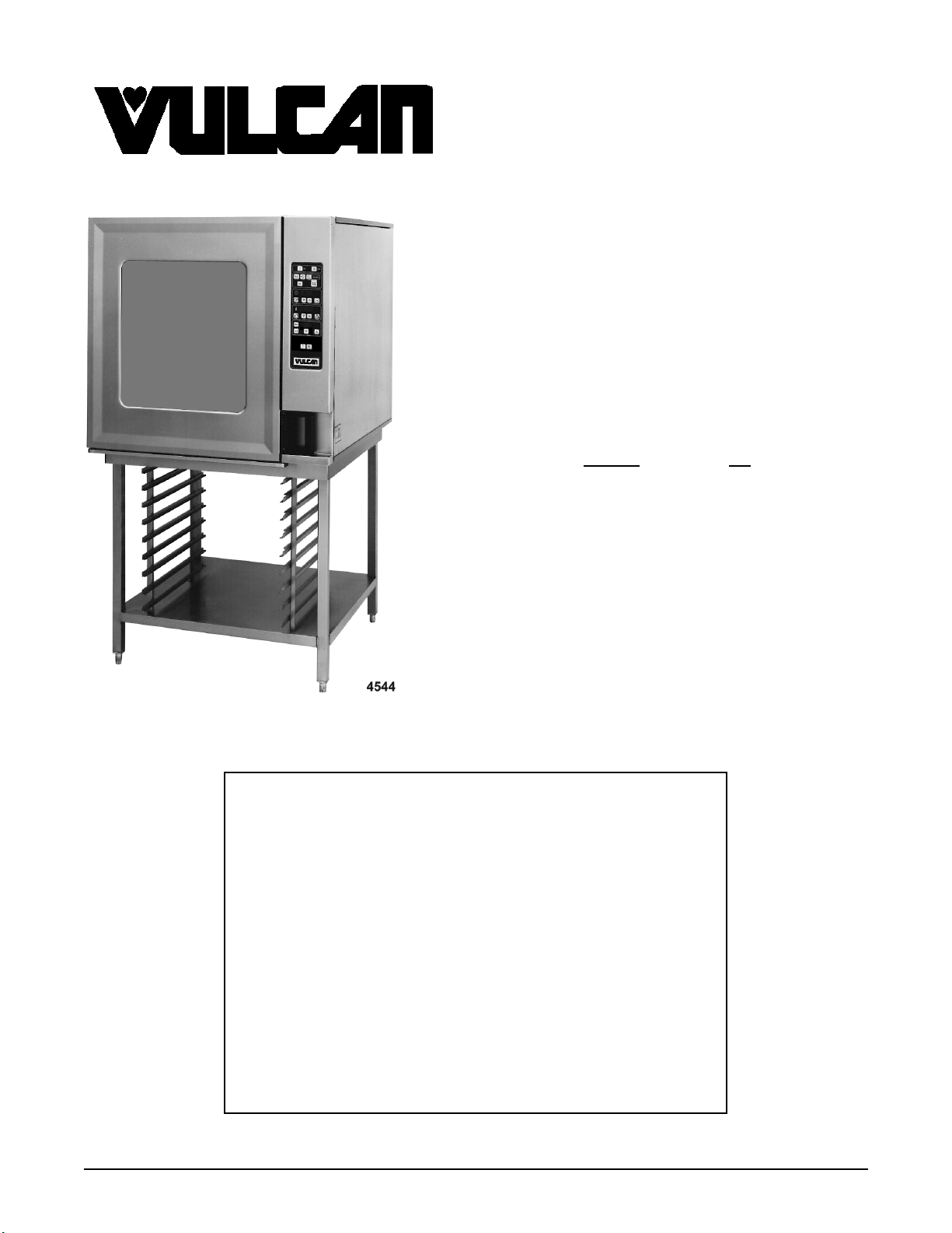
MODEL ML
VCE6H 126177
VCE10H 126178
VCE10F 126179
VCE10F SHOWN ON STAND
This Manual is prepared for th e use of trained Vulcan Service
Technicians and should not be used by those not properly
qu alif ied. If yo u have attend ed a Vulcan Service School for this
product, you may be qualified to perform all the procedures
described in this man ual.
Thi s manu al i s no t i nten ded to be al l en comp assi ng . I f you have
not atte nded a Vulca n Servic e School f or this produc t, you should
read, in its entirety, the repair procedure you wish to perform to
determine if you have the necessary tools, instruments and skills
required to perform the procedure. Procedures for which you do
not have th e necessary tools, instruments and skills should be
performed b y a trained Vu lcan Service Technician .
VCE20H 126172
VCE20F 126173
- NOTICE -
Reproduction or other use of this Manual, without the express
written consent of Vulcan-Hart, is prohibited
A product of VULCAN-HART LOUISVILLE , KY 40201-0696
Form 24659 ( S eptember 1999)
.
Page 2

ELECTRIC COMBI OVENS
TABLE OF CONTENTS
GENERAL............................................................................. 4
Introduction ........................................................................ 4
Operation.......................................................................... 4
Cleaning .......................................................................... 4
Stacking Kit Instructions............................................................... 4
Specifications ...................................................................... 4
Water Supply ................................................................... 4
Electrical ...................................................................... 5
Oven Controls ...................................................................... 6
Water Conditi oning .................................................................. 7
Lubrication ......................................................................... 7
Tools ............................................................................. 7
REMOVAL AND REPLACEMENT OF PARTS ................................................. 8
Rack Guide/ Filter /Exhaust Assembly ..................................................... 8
Covers and Panels ................................................................... 8
Oven Temperature Probe ............................................................. 9
Programable Oven Control ........................................................... 10
Manual Oven Control s ............................................................... 11
Relay Board....................................................................... 11
Blower and Motor ................................................................... 12
Blower Motor Shaft Seal ............................................................. 13
Heating Elements .................................................................. 13
Thermal Fuse(s) ................................................................... 14
Steam G ener ator Drain Pump ......................................................... 15
Vent Damper Assembly .............................................................. 15
Water Level Sensors and Wat er Equalization Tube ......................................... 16
Steam G ener ator Tank .............................................................. 17
Oven Door........................................................................ 18
Door Lamp........................................................................ 19
Ov en Door Hinges .................................................................. 19
Door Magnetic Reed Switch ........................................................... 20
Door Seal......................................................................... 20
Door Locking Mec hanism ............................................................. 20
Oven Cavity Seal................................................................... 21
Power Supply Board and T r ansformer ................................................... 22
Contactors ........................................................................ 22
Oven Cavity Drain .................................................................. 23
SERVICE PROCEDURES AND ADJUSTMENTS .............................................. 24
Configur ation Mode - Progr amable Control ............................................... 24
Diagnostic Test Mode - Program able Control .............................................. 25
Configur ation Mode - Manual Controls ................................................... 26
Diagnostic Test Mode - Manual Contr ols ................................................. 28
Service Error Lights................................................................. 29
Heating Elements .................................................................. 30
Oven Door Adjustment............................................................... 30
Buzzer Adjustment - Programable Control ................................................ 32
Buzzer Adjustment - Manual Controls ................................................... 32
Clean Cycle Mode - Steam G enerator Deli ming ............................................ 33
Battery Backup - Programable Control................................................... 35
Page 2 of 68
Page 3

ELECTRIC COMBI OVENS
ELECTRICAL OPERATION .............................................................. 37
Component Func tion ................................................................ 37
Component Locat ion ................................................................ 40
Sequence of O per ation .............................................................. 42
Heating Mode and Cavity Fan Speeds ............................................... 42
Heating Regulation .............................................................. 42
Steam Pre-Heat ................................................................ 43
Steam Regulation ............................................................... 43
Water Injection (Humidifier) ....................................................... 44
Cool Down Mode (Manual Cont r ols) ................................................. 44
Programable Oven Control........................................................ 45
Manual Oven Control s ........................................................... 49
Wiring Diagrams ................................................................... 54
6 Level ....................................................................... 54
10 Level ...................................................................... 56
20 Level ...................................................................... 58
Electric Heater Circuits .............................................................. 60
TROUBLESHOOTING .................................................................. 63
© VULCAN 1999
Page 3 of 68
Page 4
ELECTRIC COMBI OVENS - GENERAL
GENERAL
INTRODUCTION
General
The procedures in t his manual appl y to all models
unless otherwise specified. All of the information,
illustrations and specifications contained in thi s
manual are based on t he latest product information
available at the tim e of print ing.
Combi Ovens
The Elect ric Combi ovens provide convection heat,
steam heat or a c ombination of both in a single
compartment cooking chamber. Humidificat ion is
provided from the inter nal steam generat or or by
water injection into the oven cavit y. W hen the water
is injec ted by means of an internal spray nozz le, it
vaporizes on contact wit h the hot interior surfaces.
H
The ov ens are available in two depths,
(half on 6
and 20H/F).
level only) and in three sizes (6H, 10H/F
alf and Full
OPERATION
Refer to the Installation & Operat ion Manual for
specific operating instructions.
STACKING KIT INSTRUCTIONS
When servicing stacked ovens and disassembly is
required, r efer to the S tacking Ki t Instructi ons for
specific assembly procedur es.
SPECIFICATIONS
Water Supply
The fact that a water supply is potable is no
guarantee that it is suitable for steam generation.
The supply connect ion to the steam gener ator
should be “treated” water and must be within t he
guideli nes listed below. For dr ain water cooling only,
an “untreated“ water suppl y c onnec tion should be
used.
Supply Pressure
(treated and untreated water)
Supply Connections
(treated and untreated water)
Water Hardness *
Chloride less than 30 ppm
PH fact or (range) 7 to 8
(*17.1 ppm = 1 grain of har dness)
20-80 psig
cold
2-4 grains per
gallon (gpg)
CLEANING
Refer to the Installation & Operat ion Manual for
specific cleani ng instructions.
Page 4 of 68
Page 5
Electrical
ELECTRIC COMBI OVENS - GENERAL
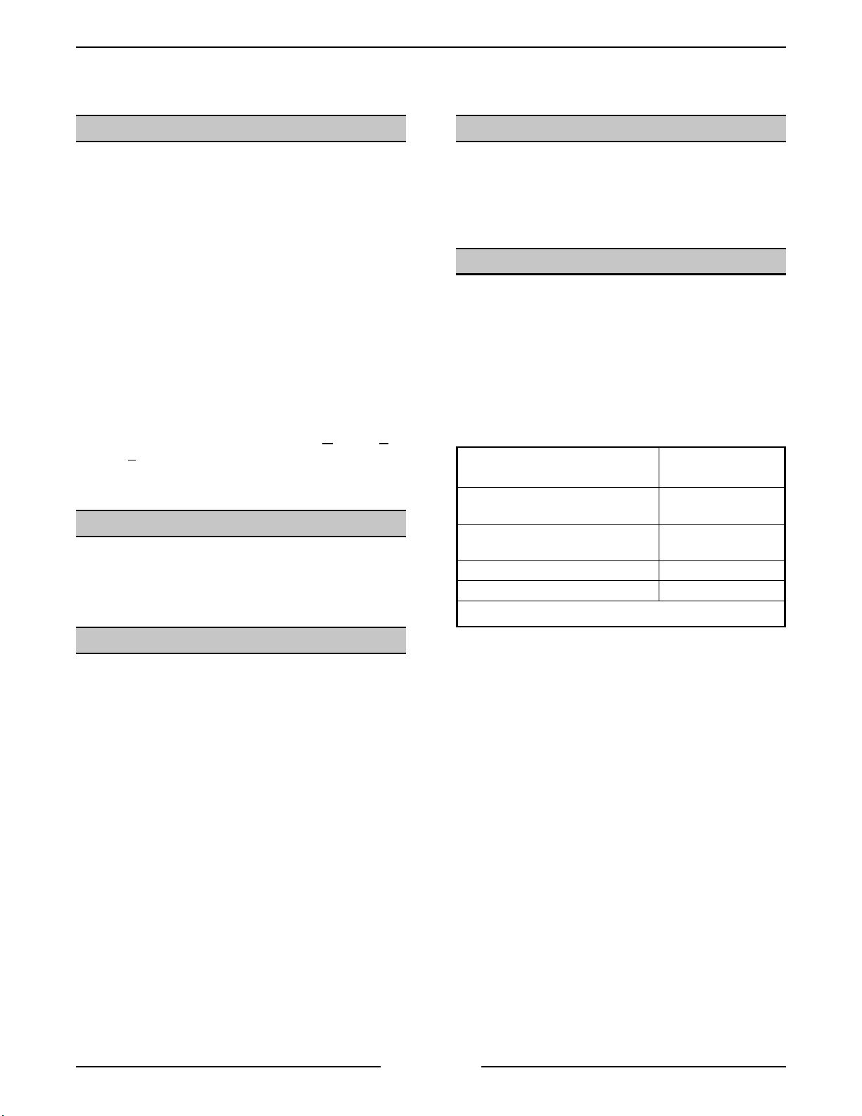
MACHINE AMPERAGE (3 PHASE/ 60HZ)
1
MODEL
VCE6H
VCE10H
VCE10F
VCE20H
VCE20F
NOTES:
POWER
(KW)
PER LINE
2
RECOMMENDED
CIRCUIT
PROTECTION
3
208V 240V 480V 208V 240V 480V
9 252211353015
18 50 43 22 70 60 30
18 50 43 22 70 60 30
24 67 58 29 90 80 40
36 100 87 43 125 110 60
1. Amperage values in t he table are nominal. T olerance
is +5/-10%.
2. Line currents must
be measured in full power
convec tion heat m ode.
3. Complied in accordance with National Electric Code,
ANSI/NFPA 70, latest edition.
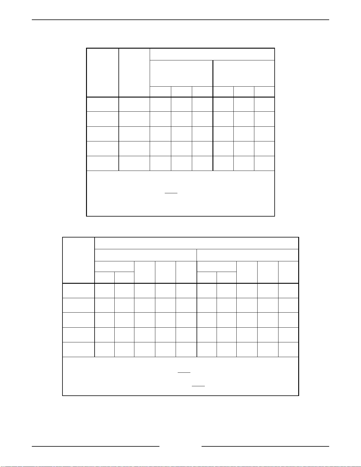
MODEL
VCE6H
VCE10H
VCE10F
VCE20H
VCE20F
NOTES:
1
INDIVIDUAL AMPERAGE (3 PHASE/ 60HZ)
CONVECT ION HEAT
ELEMENTS
2
208V 240V 480V
STEAM GENE RATOR HEAT
ELEMENTS
208V 240V 480V
KW NO. KW NO.
9 1 25 22 11 8 1 22 19 10
9 2 50 43 22 8 2 45 39 19
9 2 50 43 22 8 2 45 39 19
6 4 67 58 29 8 3 67 58 29
9 4 100 87 43 8 4 89 77 39
1. Amperage values in the table are nomi nal. Tolerance is +5/-10%.
2. Convection heater currents must
be measured in full power convection
heat mode.
3. Steam generator heater currents m ust
be measured in full power steam
mode.
3
Page 5 of 68
Page 6
ELECTRIC COMBI OVENS - GENERAL
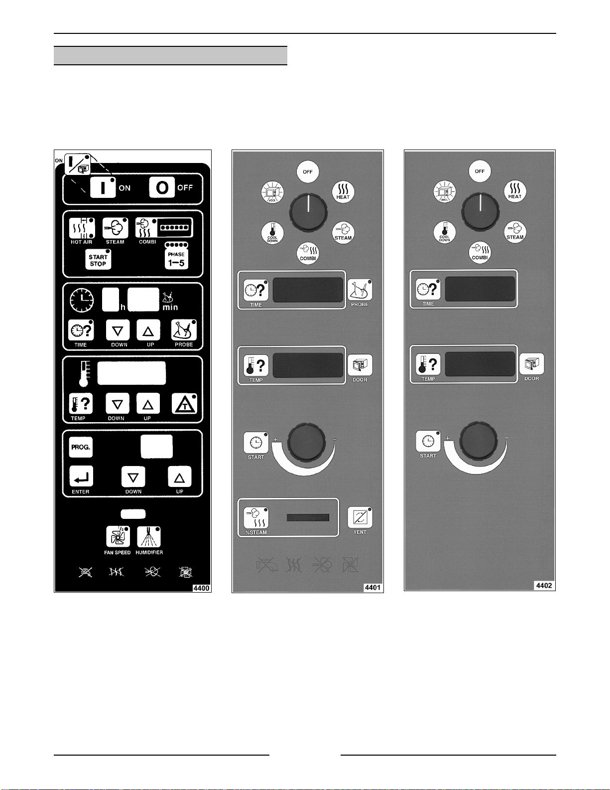
OVEN CONTROLS
PROGRAMMABLE STANDARD MANUALDELUXE MANUAL
Page 6 of 68
Page 7

ELECTRIC COMBI OVENS - GENERAL
WATER CONDITIONING
Furnishing the steam generator with treated water to
reduce scale formation is impor tant. Scal e formation
will reduce steam out put, cause prematur e
component failur e, and shorten equipm ent life. Most
water supplies contai n scale producing m inerals
such as Calcium and M agnesi um. As steam is
generated, the minerals remain and dissolve int o
the water. As the concentration of these miner als
increases past a certai n point, they pr ec ipitate from
the water and coat the inside of t he steam
generator, heating elements, and water level
sensors. Because of the high temperature of these
surfaces, the pr ec ipitated mineral s bake ont o them
and become very difficult to r emov e.
This may c ause several probl ems:
1. Reduced heat transf er eff iciency.
2. Premature heating element failures.
3. False readings from water l evel sensors.
These problem s are common to any manufacturer's
steamer regardless of design, but t hey c an all be
minimized by furnishing the steam generat or with
treated water.
Other factors affecting steam generati on ar e iron
content, amount of c hloridation and dissolved
gases.
The desired water propert ies can best be achieved
by using a
system.
The water level probes in the steam generator use
ions in the water t o detect the water level.
use fully demineralized or de-ionized water
since it is "non conductive" and the water level
can not be detected.
properly maintained water treatment
Do not
LUBRICATION
Cavity fan motor has sealed beari ngs and
requires no addit ional lubrication.
Cavity fan motor shaft seal requires lubr ication
at replacement (White silicone grease 544268).
TOOLS
Standard
Standard set of hand tools.
Metric set of hand tools.
VOM with AC c ur r ent tester (any quality VOM
with a sensitivit y of at least 20,000 ohms can
be used).
Gear puller to remove cavity fan.
Temperat ure meter wit h thermocoupl e.
Special
Red High Tem perature RTV for door seal and
probes (P/N 544313 or 542949).
Grounding kit to protec t control board( s) if
handled (P/N TL-84919).
Motor Shaft Centering Tool (P/N 359450) .
28 pin EPROM extraction tool and 28 pi n
EPROM i nsert ion tool (purc hase l oc ally).
Scalekleen deliming chemical or the
recommended chemi c al for t he water treatment
system in use for deliming of the steam
generator. (S c alekleen is avail able through the
Serv ice Parts Distr ibution Center or locally
through an Everpure dealer)
The use of strainers, or filters will not remove
minerals from the water.
Water supplies vary fr om state to state and from
locati ons wit hin a state. Therefore, Vulcan
recommends that a local water treatm ent specialist
be consulted bef ore the installation of any steam
generating equi pment.
Steamers that operate over a long peri od of time
without the benefit of a water treatment system,
which have developed a heavy scale build up,
should be cleaned before using the system.
Page 7 of 68
Page 8
ELECTRIC COMBI OVEN - REMOVAL AND REPLACEMENT OF PARTS
REMOVAL AND REPLACEMENT OF PARTS
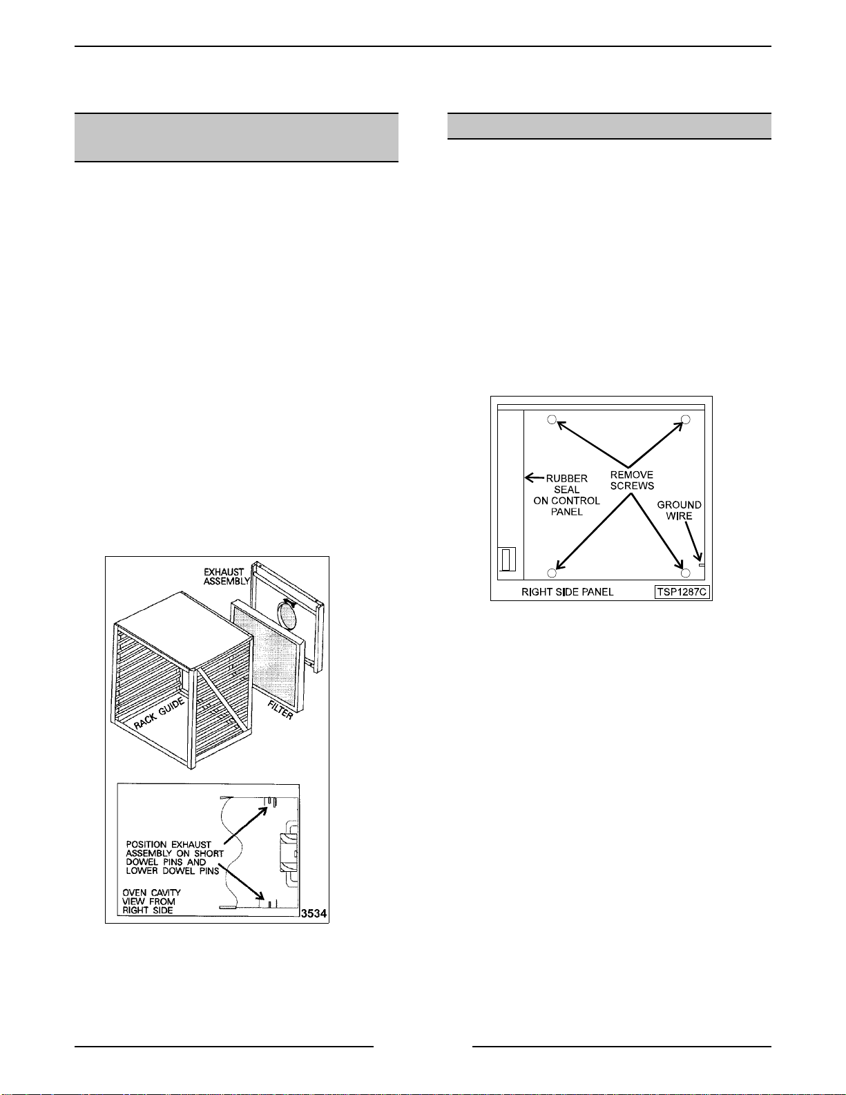
RACK GUIDE/FILTER/EXHAUST
ASSEMBLY
1. Turn the oven off.
2. Remove the racks (i f equipped).
3. Push the rack guide to rear of oven to remove
the rack guide tabs from sl ots in the exhaust
assembly (10 level).
4. Lift the rear of the rack guide up and pull the
guide out of the ov en c avity.
5. Lift the filter up, then pull forward to remove the
filter (2 filter s on 20 level).
WARNING:
POWER TO T HE MACHINE AT THE MAIN
CIRCUIT BO X. P LA CE A TAG ON THE CI RCUIT
BOX INDICATING THE CIRCUIT IS BEING
SERVICED.
6. Lift up on exhaust assembly then pull forward
at bottom to clear t he dowel pins.
7. After lower dowel pins have been c leared,
remove assembly from t op pins and remove
from oven.
DISCONNECT THE ELECTRICAL
COVERS AND PANELS
WARNING:
POWER TO T HE MACHINE AT THE MAIN
CIRCUIT BO X. P LA CE A TAG ON THE CI RCUIT
BOX INDICATING THE CIRCUIT IS BEING
SERVICED.
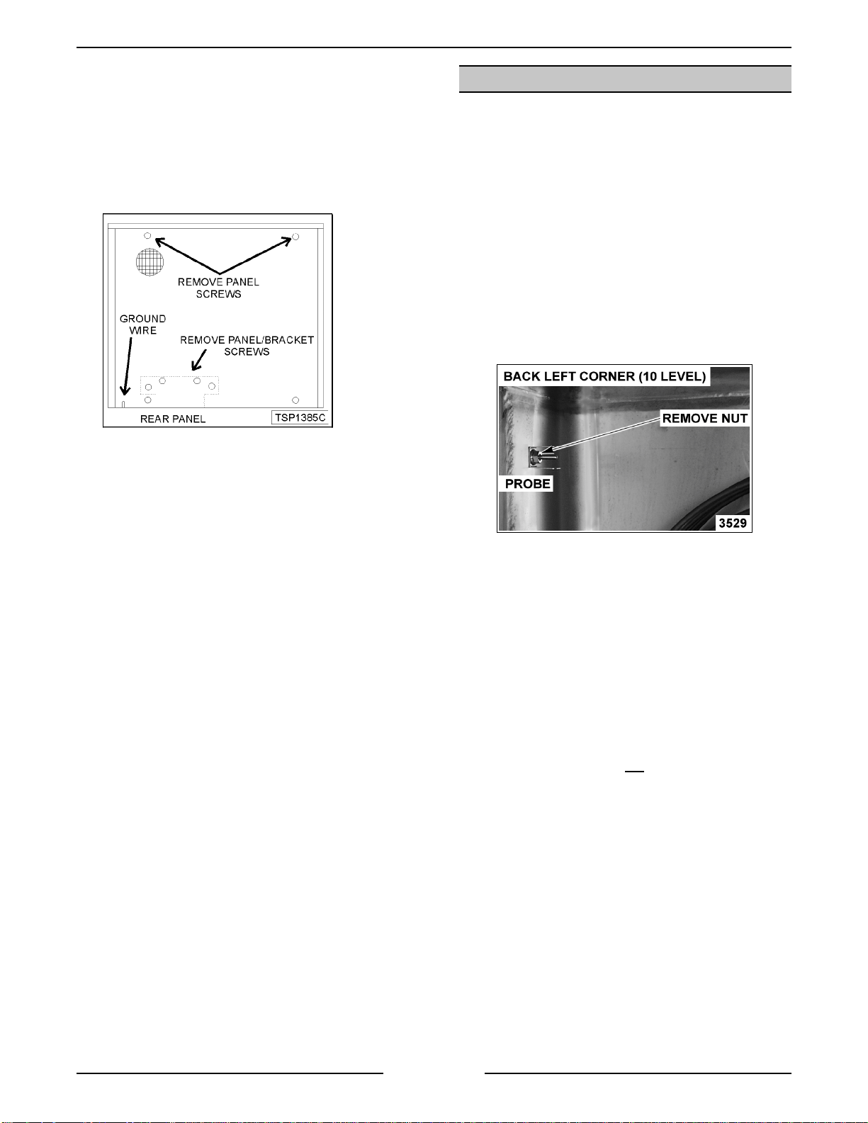
Side Panels
1. Remove the screws from the side panel f or the
side in need of access. Hold the panel in place
before removing the last screw.
2. Access the inside edge of the panel at the
bottom r ear corner and disconnect the ground
wire (if present).
DISCONNECT THE ELECTRICAL
8. Reverse proc edur e to install .
NOTE:
is seated on the dowel pins and fan direction arrow
is pointing to lef t (facing oven).
Be sure the bottom of the exhaust assembly
3. Remove the panel.
NOTE:
ensure the gasket at the rear of the contr ol panel
seals properly agai nst the front edge of the ri ght
side panel.
4. Reverse proc edur e to install .
When r e-install ing the right si de panel,
Page 8 of 68
Page 9
ELECTRIC COMBI OVEN - REMOVAL AND REPLACEMENT OF PARTS
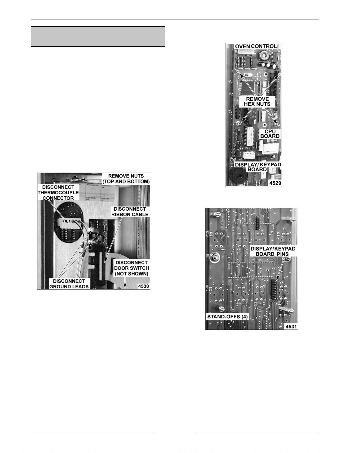
Rear Panel
1. Remove the screws from the rear ov en panel.
Hold the panel in place before removing the
last panel screw.
2. Access the inside edge of the panel at the
bottom left and disconnect the ground wire ( if
present).
3. Lower the panel to remove from oven.
4. Reverse proc edur e to install .
OVEN TEMPERATURE PROBE
WARNING:
POWER TO T HE MACHINE AT THE MAIN
CIRCUIT BO X. P LA CE A TAG ON THE CI RCUIT
BOX INDICATING THE CIRCUIT IS BEING
SERVICED.
1. Remove the rack gui de, filter and exhaust
assembly as outlined under “RACK GUIDE/
FILTER/EXHAUST ASSEMBLY”.
2. Remove both side panels as outl ined under
“COVERS AND PANELS”.
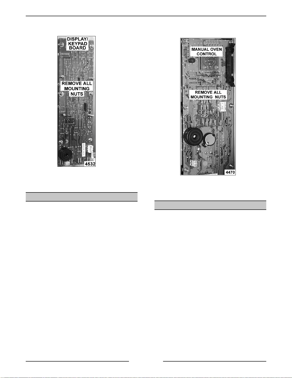
3. Remove the retai ning nut fr om the probe inside
the ov en ( 2 probes on 20 level) and lift bracket
off.
DISCONNECT THE ELECTRICAL
Control Panel
1. Remove the right side panel as outli ned.
2. Disconnect the r ibbon cable, t her mocouple
connector, gr ound leads and door switch
connector from the oven control board.
3. Remove the nuts at the t op and bottom of
control panel that secure it to the f r ame.
CAUTION
damage may result to the oven control if dr opped.
4. Reverse proc edur e to install .
: Hold contr ol panel duri ng r emov al or
4. Remove probe(s) through the left si de of the
oven cavity.
NOTE:
silicone between the probe and the hole in the oven
cavity wall.
NOTE:
position as shown.
5. Disconnect the pr obe leads from the control
6. Reverse proc edur e to install .
NOTE
rotate unless secured. Do not
or damage m ay result.
When r eplacing, use hi gh temperature
Be sure to replace br ac k et around probe and
board connector.
: When tightening retaini ng nut, probe will
clamp down on probe
Page 9 of 68
Page 10
ELECTRIC COMBI OVEN - REMOVAL AND REPLACEMENT OF PARTS
PROGRAMABLE OVEN
CONTROL
WARNING:
POWER TO T HE MACHINE AT THE MAIN
CIRCUIT BO X. P LA CE A TAG ON THE CI RCUIT
BOX INDICATING THE CIRCUIT IS BEING
SERVICED.
CAUTION: Certain components in this system
are subject to damage by electrostatic discharge
during field repairs. A field service ground kit is
available t o prevent damage. Th e f ield service
grounding kit must be used anytime the control
board is handled.
1. Remove the right side panel as outli ned under
“COVERS AND PANELS”.
2. Disconnect the r ibbon cable, connec tors and
ground leads fr om the oven control boar d.
DISCONNECT THE ELECTRICAL
4. Remove the hex nut s securi ng the CPU board
to the display/keypad board.
5. Pull out wards on the CPU boar d and lif t it off
from the display/keypad board pin connections.
3. Remove the cover from the oven control by
removing the mounting nuts at the top and
bottom.
NOTE:
keypad board, make sure that the pi ns on the
keypad board are aligned with the plug on the
control boar d.
Page 10 of 68
When installing the control board onto the
Page 11
ELECTRIC COMBI OVEN - REMOVAL AND REPLACEMENT OF PARTS
6. Remove the display/keypad board from the
control panel by removing the mounting nuts.
4. Remove the oven control board from the
control panel by removing the mounting nuts.
7. Reverse proc edur e to install .
MANUAL OVEN CONTROL S
WARNING:
POWER TO T HE MACHINE AT THE MAIN
CIRCUIT BO X. P LA CE A TAG ON THE CI RCUIT
BOX INDICATING THE CIRCUIT IS BEING
SERVICED.
CAUTION: Certain components in this system
are subject to damage by electrostatic discharge
during field repairs. A field service ground kit is
available t o prevent damage. Th e f ield service
grounding kit must be used anytime the control
board is handled.
1. Remove the right side panel as outli ned under
“COVERS AND PANELS”.
2. Disconnect the r ibbon cable, t her mocouple
connector, gr ound leads and door switch
connector from the oven control board.
3. Remove the cover from the oven control boar d
by removing the mounting nut s at the top and
bottom.
DISCONNECT THE ELECTRICAL
5. Reverse proc edur e to install .
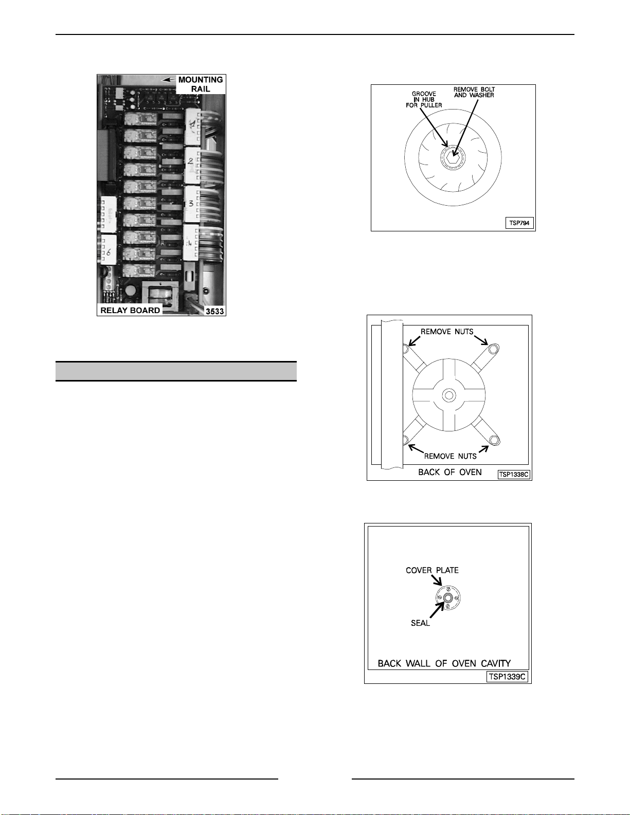
RELAY BOARD
WARNING:
POWER TO T HE MACHINE AT THE MAIN
CIRCUIT BO X. P LA CE A TAG ON THE CI RCUIT
BOX INDICATING THE CIRCUIT IS BEING
SERVICED.
CAUTION: Certain components in this system
are subject to damage by electrostatic discharge
during field repairs. A field service ground kit is
available t o prevent damage. Th e f ield service
grounding kit must be used anytime the control
board is handled.
1. Remove the right side panel as outli ned under
“COVERS AND PANELS”.
2. Disconnect lead wi r es from the r elay board.
DISCONNECT THE ELECTRICAL
Page 11 of 68
Page 12
ELECTRIC COMBI OVEN - REMOVAL AND REPLACEMENT OF PARTS
3. Release the clips on the back of the mounti ng
rail.
4. Reverse proc edur e to install .
NOTE:
the procedure at this point to install.
5. Remove the rear panel as outlined under
6. Disconnect the lead wires from the motor .
7. Remove the mot or from the back of t he oven
If only the blower is bei ng r emov ed, rever se
“COVERS AND PANELS”.
by removing the mounting nut s.
BLOWER AND MOTOR
WARNING:
POWER TO T HE MACHINE AT THE MAIN
CIRCUIT BO X. P LA CE A TAG ON THE CI RCUIT
BOX INDICATING THE CIRCUIT IS BEING
SERVICED.
Removal
1. Remove the rack gui de, filter and exhaust
assembly as outlined under “RACK GUIDE/
FILTER/EXHAUST ASSEMBLY”.
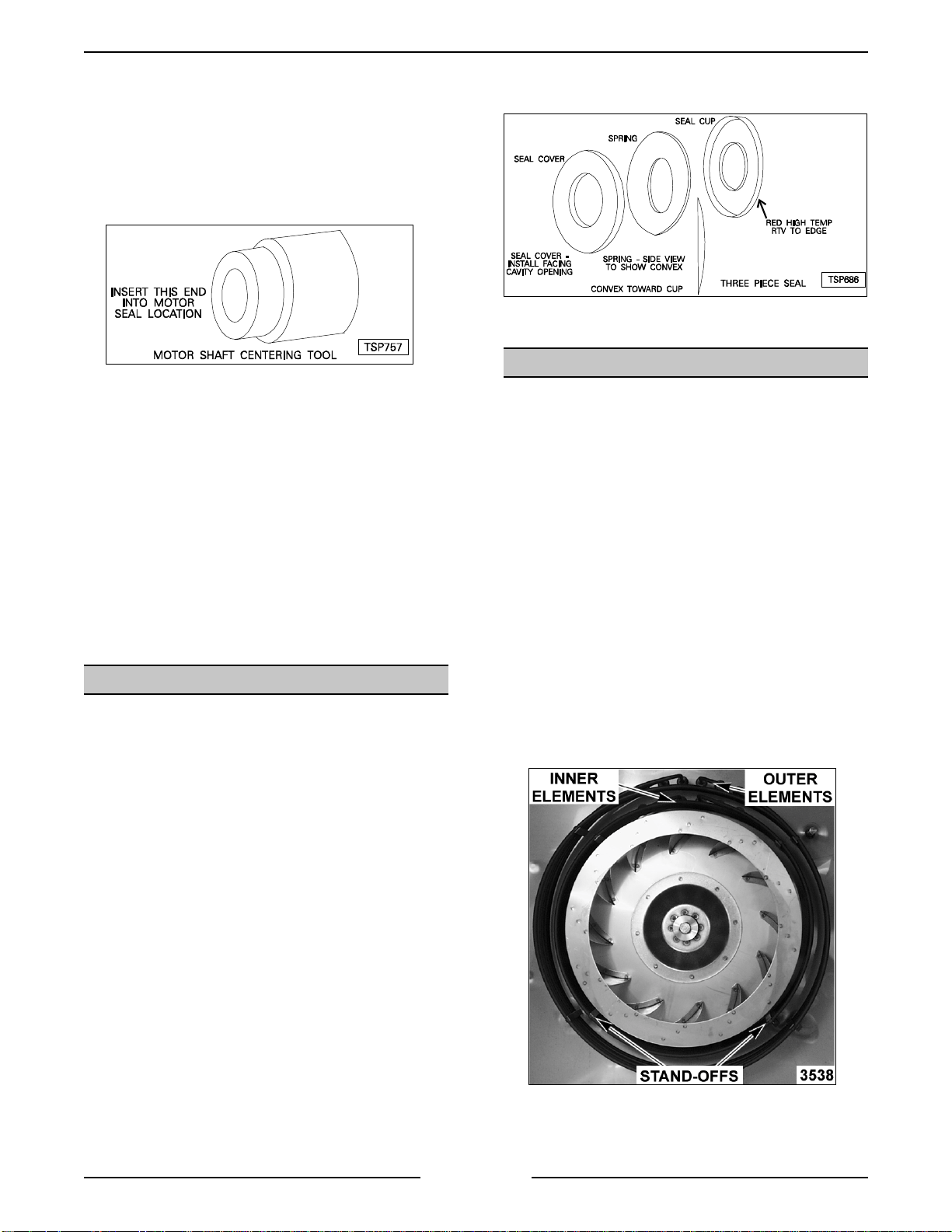
2. Loosen bolt (one turn) that secures the blower
and install puller.
3. Tighten t he puller, then tap the puller with a
hammer to loosen the blower from the motor
shaft.
4. Remove the pull er , bolt, washer and blower
from the motor shaft.
DISCONNECT THE ELECTRICAL
8. Remove the cover plate and seal from inside
the ov en c avity.
NOTE:
back of t he oven.
Page 12 of 68
You may have to dri ve the seal out from the
Page 13
ELECTRIC COMBI OVEN - REMOVAL AND REPLACEMENT OF PARTS
Installation
1. Mount the m otor to the back of the oven.
Tighten t he bolts enough to hold the motor i n
place, but allow some movem ent.
2. Ensure that the motor shaft is centered (use
shaft center ing tool) in the mot or shaft hole and
tighten mounting bol ts.
3. Remove the shaft c entering tool .
4. Connect the lead wi r es to the motor.
5. Install seal and cover as outlined under
“BLOWER MOTO R SHAFT SEAL”.
: Remove all traces of m otor seal grease from
NOTE
the motor shaft.
6. Install the blower wheel.
7. Install exhaust assembly, fil ter, and rack gui de
as outlined under “RACK
GUIDE/FILTER/EXHAUST ASSEMBLY”.
8. Install rear panel as outlined under “COVERS
AND PANELS”.
BLOWER MOTOR SHA FT SEAL
WARNING:
POWER TO T HE MACHINE AT THE MAIN
CIRCUIT BO X. P LA CE A TAG ON THE CI RCUIT
BOX INDICATING THE CIRCUIT IS BEING
SERVICED.
DISCONNECT THE ELECTRICAL
: Remove all traces of m otor seal grease from
NOTE
the motor shaft.
7. Install the seal cover plate and then the blower.
HEATING ELEMENTS
WARNING:
POWER TO T HE MACHINE AT THE MAIN
CIRCUIT BO X. P LA CE A TAG ON THE CI RCUIT
BOX INDICATING THE CIRCUIT IS BEING
SERVICED.
Oven Cavity
1. Remove the rack gui de, filter and exhaust
assembly as outlined under “RACK GUIDE/
FILTER/EXHAUST ASSEMBLY”.
2. From inside the oven cavity, remove the nuts
from the heating element stand-offs for the
element being replaced.
3. Remove the rear panel as outlined under
“COVERS AND PANELS”.
4. Disconnect the lead wires from the elem ents at
the rear of the oven.
5. Remove the nuts and washers from the
element being replaced t hen r emov e the
element.
DISCONNECT THE ELECTRICAL
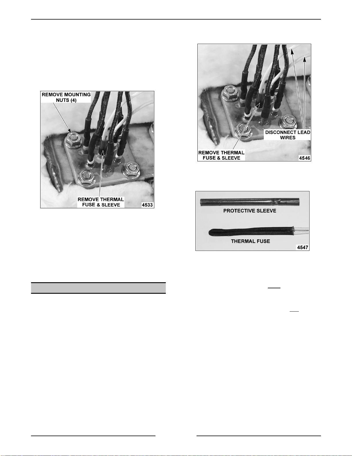
1. Remove blower as outli ned under “BLOWER
AND MOTOR”.
2. Remove motor seal c over pl ate.
3. Remove the seal f r om the recess in the r ear
oven wall.
NOTE:
back of t he oven.
4. Fill replacement seal cover with white silicone
5. Assemble the motor seal with t he c onvex par t
6. Apply red high temperat ur e RTV to the outer
You may have to dri ve the seal out from the
grease.
of the spri ng toward the motor.
edge of the seal to help hold i t in the recess
and install the seal with the seal c over toward
the front of the oven cavity.
6. Reverse proc edur e to install .
Page 13 of 68
Page 14
ELECTRIC COMBI OVEN - REMOVAL AND REPLACEMENT OF PARTS
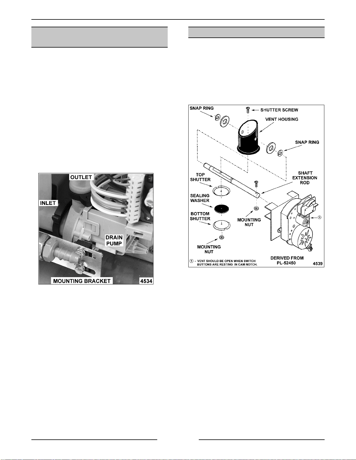
Steam Generato r
1. Turn off the water supply to the steam
generator.
2. Remove the right side panel as outli ned under
“COVERS AND PANELS”.
3. Remove the thermal fuse and prot ective sleev e
from the heater thermowell.
2. Disconnect the t hermal fuse(s) lead wire
connections.
3. Remove the thermal fuse and prot ec tive sleeve
from the heater thermowell.
4. Disconnect the heating element lead wire
connections.
5. Remove the heating element from t he steam
generator by removing the mounting nuts.
NOTE:
supplied gasket and ensure the mating surfaces are
clean.
6. Reverse proc edur e to install .
When installing a new heater, use the
THERMAL FUSE(S)
WARNING:
POWER TO T HE MACHINE AT THE MAIN
CIRCUIT BO X. P LA CE A TAG ON THE CI RCUIT
BOX INDICATING THE CIRCUIT IS BEING
SERVICED.
1. Remove the right side panel as outli ned under
“COVERS AND PANELS”.
DISCONNECT THE ELECTRICAL
4. Reverse proc edur e to install .
: When replacing thermal fuse, be sure to
NOTE
insert the protective sleeve and thermal fuse
together. T he protective sleeve must
into the heat er thermowell with the fuse to avoid
chafi ng of the fuse leads.
: When replacing thermal fuse do
NOTE
lead wires apart. This may break the contact
juncti on or damage the connections.
be inserted
pull the
not
Page 14 of 68
Page 15
ELECTRIC COMBI OVEN - REMOVAL AND REPLACEMENT OF PARTS
STEAM GENERATOR DRAIN
PUMP
1. Turn off the oven and allow the steam
generator to drain.
WARNING:
POWER TO T HE MACHINE AT THE MAIN
CIRCUIT BO X. P LA CE A TAG ON THE CI RCUIT
BOX INDICATING THE CIRCUIT IS BEING
SERVICED.
2. Turn off the water supply.
3. Remove the right side panel as outli ned under
“COVERS AND PANELS”.
4. Disconnect l ead wir es and hoses connected to
the drain pump.
5. Remove the bolts from the mounting brac ket
that secure the pump.
DISCONNECT THE ELECTRICAL
VENT DAMPER ASSEMBLY
WARNING:
POWER TO T HE MACHINE AT THE MAIN
CIRCUIT BO X. P LA CE A TAG ON THE CI RCUIT
BOX INDICATING THE CIRCUIT IS BEING
SERVICED.
DISCONNECT THE ELECTRICAL
VENT DAMPER ASSEMBLY DIAGRAM
6. Reverse proc edur e to install .
Vent Motor
1. Remove the right side panel as outli ned under
“COVERS AND PANELS”.
2. Disconnect the lead wires from the switch and
motor.
3. Remove the screw and nut behind the motor
assembly that c onnec ts motor to shaft
extension rod.
4. Remove the mot or and swit c h assembly from
the ov en by sliding the mounting brac k et out
from the ov en frame.
5. Reverse proc edur e to install .
Page 15 of 68
Page 16

ELECTRIC COMBI OVEN - REMOVAL AND REPLACEMENT OF PARTS
Sealing Washer
1. Remove the right side panel as outli ned under
“COVERS AND PANELS”.
2. Open the oven door and remove the rack
guide, filter and exhaust assembly as outlined
under “RACK GUIDE/FILTER/EXHAUST
ASSEMBLY”.
WARNING:
POW E R TO BE APPLIED TO THE UNI T DURING
THE ADJUSTMENT. USE EXTREME CAUTION AT
ALL TIMES.
3. Reconnect the el ectrical power to the machine
at the main circuit box.
4. Close the door, turn the oven ON and press the
Start/S top button.
5. Observe the rotation of the vent motor cam.
When the cam stops turning then the vent
should be closed.
NOTE
opened, the vent should open automatical ly.
6. Disconnect the electric al power to the machine
at the main circuit box. P lace a tag on the
circuit box indicating the circui t is being
serviced.
NOTE
manner. I f the oven is turned OFF or the door is
opened, the vent will re-open automatical ly.
7. Open the oven door and examine the vent f r om
inside the cavit y.
A. If the mounting nut is vi si ble, proceed to
B. If the mounting nut is not visible, t hen the
8. Remove the nut securing both shutters and the
sealing washer to the shaft extension rod then
remove the shutters and sealing washer.
THE FOLLOWI NG ST EPS REQUIRE
: When the ov en is turned OFF or the door is
: Power to the oven must be removed in this
step 8.
vent needs to r otate 180 degrees.
Reconnect power to the machine and
repeat steps 3 through 7A.
4. Rotate the extension rod approximately 90
degrees by hand.
5. Exam ine the vent from inside the c avity.
A. If the mounting nut is vi si ble, proceed to
step 6.
B. If the mounting nut is not visible, t hen the
extension rod needs t o r otate
approximately 90 degrees more.
6. Remove the nut securing both shutters and the
sealing washer to the ex tension rod then
remove the shutters and sealing washer.
7. Remove the shutter screw f r om the extension
rod.
8. Release the snap ring on the left end of the
shaft (i f fac ing oven) and pull shaft extension
out.
: If the washers on the exterior of the vent
NOTE
housing come loose, red silicone must be re-appli ed
to prevent steam l eakage above the oven cavity .
9. Reverse proc edur e to install .
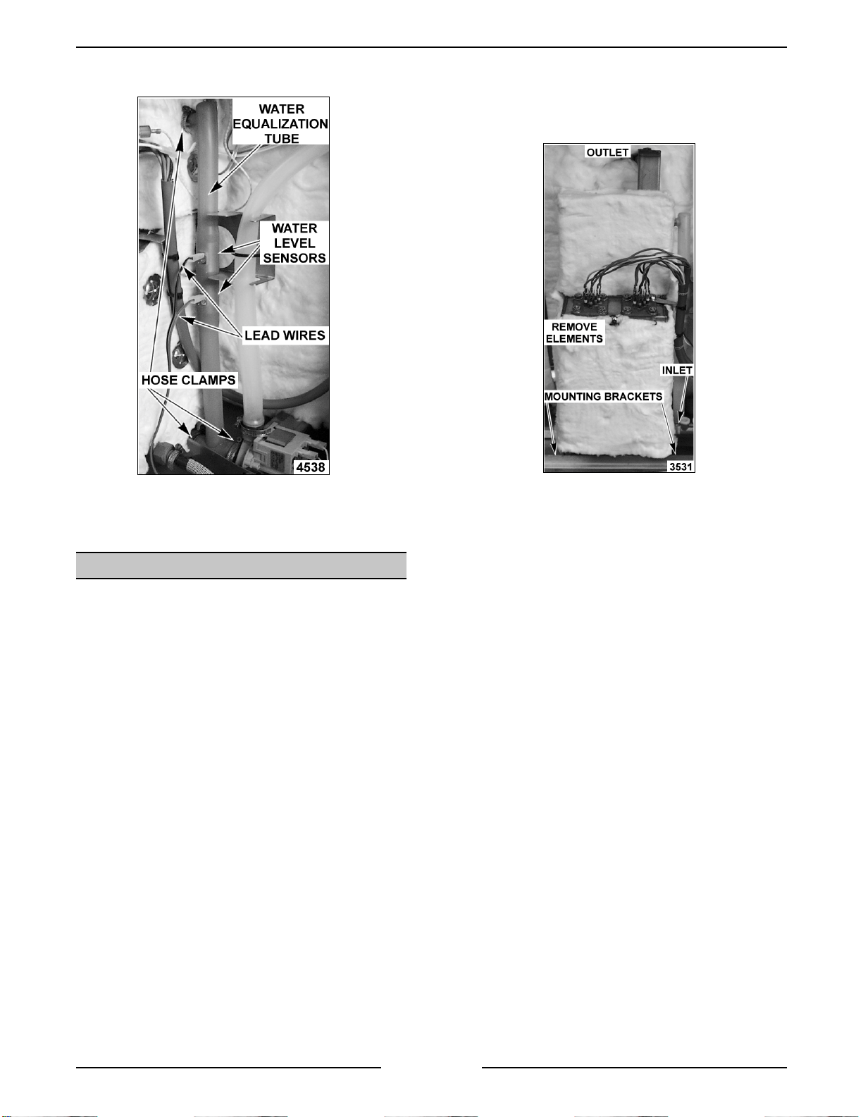
WATER LEVEL SENSORS AND
WATER EQUALIZATION TUBE
1. Turn the oven off and allow steam generator
tank to drai n.
WARNING:
POWER TO T HE MACHINE AT THE MAIN
CIRCUIT BO X. P LA CE A TAG ON THE CI RCUIT
BOX INDICATING THE CIRCUIT IS BEING
SERVICED.
2. Turn off the water supply.
3. Remove the right side panel as outli ned under
”COVERS AND PANELS”.
4. Disconnect l ead wir es and hose clamps from
the water equali z ation tube.
DISCONNECT THE ELECTRICAL
9. Install new sealing washer and re-assemble.
Shaft Extension
1. Remove the left, ri ght and rear panels as
outlined under “COVERS AND PANELS”.
2. Open the oven door and remove the rack
guide, filter and exhaust assembly as outlined
under “RACK GUIDE/FILTER/EXHAUST
ASSEMBLY”.
3. Remove the screw and nut behind the motor
assembly that c onnec ts motor to shaft
extension rod.
NOTE
Page 16 of 68
: Some water will continue to drain out.
Page 17
ELECTRIC COMBI OVEN - REMOVAL AND REPLACEMENT OF PARTS
5. Remove the water equalization tube.
4. Disconnect water and steam equalizat ion tube
from the steam generator. If necessary, loosen
or remove drain pump mounting nuts to
remove tube.
6. Reverse proc edur e to install .
STEAM GENERAT OR TANK
1. Turn the oven off and allow the steam
generator tank to drain.
WARNING:
POWER TO T HE MACHINE AT THE MAIN
CIRCUIT BO X. P LA CE A TAG ON THE CI RCUIT
BOX INDICATING THE CIRCUIT IS BEING
SERVICED.
2. Turn off the water supply to the steam
generator
3. Remove the right side and rear panels as
outlined under “COVERS AND PANELS”.
DISCONNECT THE ELECTRICAL
10 LEVEL SHOWN
A. Remov e heating elements from steam
generator tank and place to the side.
NOTE
: Unless replacing the heating
element (s), it not nec essary to r emov e the
heating element lead wir es.
B. On 6 and 10 levels, remove cl amp from
the steam exhaust hose at the top of
steam generator and disconnect hose. On
20 levels, remove the nut s securing the
steam exhaust pipe to the outsi de of the
cavity.
NOTE
: When replacing tank on 20 levels, be
sure to seal the m ating surface between the
exhaust pipe and cavity wall with RT V .
5. Remove the nuts fr om the tank mounting studs
and bracket (at bottom) t hen r emov e the steam
generator f rom the oven.
6. Remove insulation from the old steam
generator and use on the repl ac ement steam
generator.
7. Reverse proc edur e to install .
Page 17 of 68
Page 18
ELECTRIC COMBI OVEN - REMOVAL AND REPLACEMENT OF PARTS
OVEN DOOR
WARNING:
POWER TO T HE MACHINE AT THE MAIN
CIRCUIT BO X. P LA CE A TAG ON THE CI RCUIT
BOX INDICATING THE CIRCUIT IS BEING
SERVICED.
Removal
1. Remove the left and right si de panels as
outlined under “COVERS AND PANELS”.
2. Disconnect the lead wires to the lamp on the
power supply board term inal block and r oute
them so they can be pulled through the hole in
the frame when the door is rem oved.
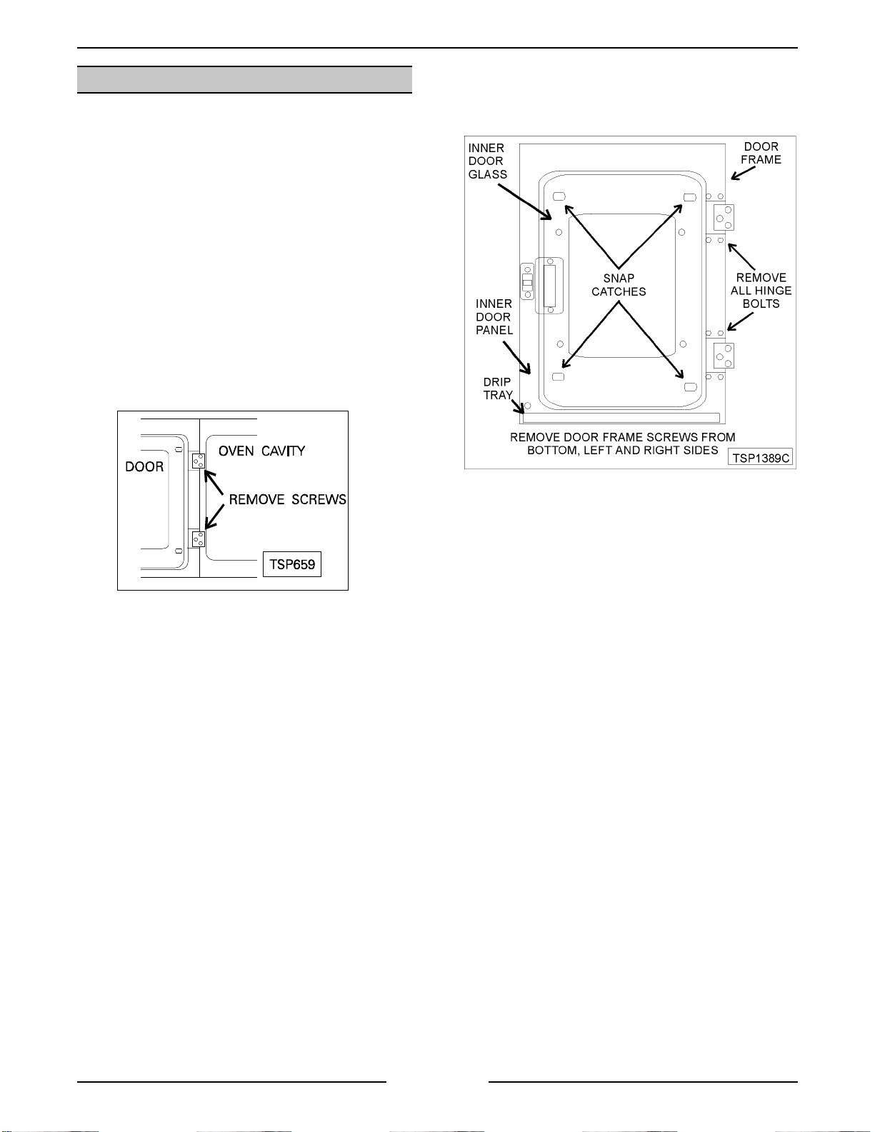
3. Support the door, remove the screws from
each hinge block on the oven and r emov e
door.
DISCONNECT THE ELECTRICAL
4. Open the inner door glass and remove the cring clamps from the rear snap catches, unsnap
at the rear then lif t off.
4. Reverse proc edur e to install .
Disassembly
1. Remove the door f r om the oven as outlined
above in “REMOVAL”.
2. Lay the door on a f lat surfac e with the inside of
the door fac ing up.
3. Lift up along the inner door glass edge near the
door latch and unsnap the glass from t he “snap
catches” in the oven door.
CAUTION: When replacing the inner door glass,
it must be installed with the conductive side
toward the front o f t he oven. Use an ohmmeter
to verify the conductive side. Set the meter to
read ohms and touch glass with the meter leads.
A resistance will be measured but will vary
depending on the distance between the meter
leads, grease and/or o t her substances o n the
glass.
5. Remove the bolts securing the top and bottom
hinges to the door.
6. Remove the drip t r ay, remaining screws from
the inner door panel, the screws at the left,
right and bottom of the door and remove the
door handle.
7. Lift the inner door panel from the outer door
frame.
8. Remove the outer door glass.
9. Reverse proc edur e to install .
10. Adjust the door as outlined under “OVEN
DOOR ADJUSTMENT” in “SERVICE
PROCEDURES AND ADJUSTMENTS”.
Page 18 of 68
Page 19
ELECTRIC COMBI OVEN - REMOVAL AND REPLACEMENT OF PARTS
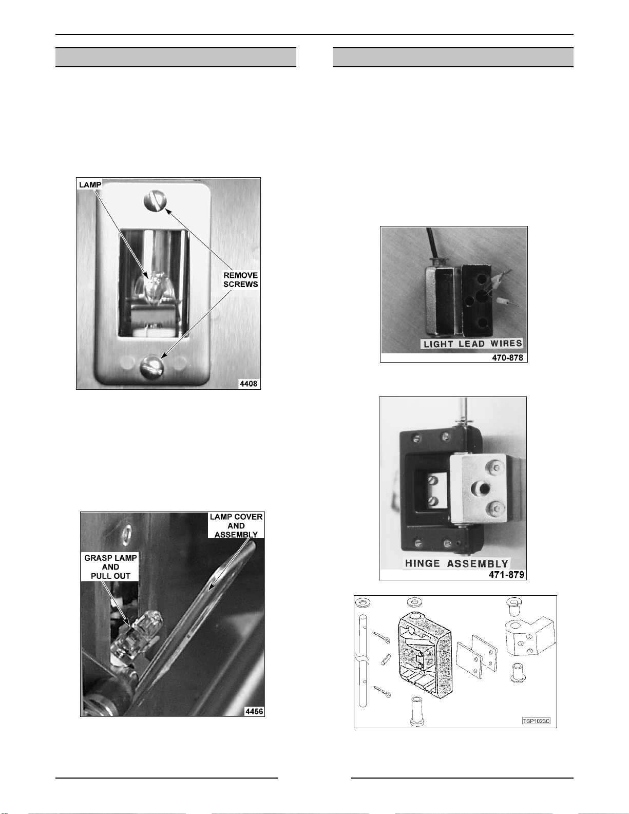
DOOR LAMP
WARNING:
POWER TO T HE MACHINE AT THE MAIN
CIRCUIT BO X. P LA CE A TAG ON THE CI RCUIT
BOX INDICATING THE CIRCUIT IS BEING
SERVICED.
1. Remove the screws holding the cover and
gasket.
DISCONNECT THE ELECTRICAL
OVEN DOOR HINGES
WARNING:
POWER TO T HE MACHINE AT THE MAIN
CIRCUIT BO X. P LA CE A TAG ON THE CI RCUIT
BOX INDICATING THE CIRCUIT IS BEING
SERVICED.
1. Remove and disassemble the door as outlined
under “OVEN DOOR”.
2. Remove the li ght lead wire from the hinge.
NOTE:
wires at the terminal end t o allow the terminals to be
fed through the hinge one at a time.
DISCONNECT THE ELECTRICAL
Strip 3 inches of the shielding away from the
2. Pull t he lamp and socket assembly out f r om the
door.
3. Hold the lamp assembly and grasp the bulb
using a cloth.
NOTE
: Do not touch t he Halogen lamp with bare
hands. If lamp is ex posed t o oil f r om the skin, the
life will be reduced. Ensure lamp is free from oil and
dirt before replacing.
3. Remove the cotter pins from the shaft and
remove the shaft from the hinges.
4. Pull up on light bulb to remove it from socket.
5. Reverse proc edur e to install .
4. Reverse proc edur e to install .
Page 19 of 68
Page 20
ELECTRIC COMBI OVEN - REMOVAL AND REPLACEMENT OF PARTS
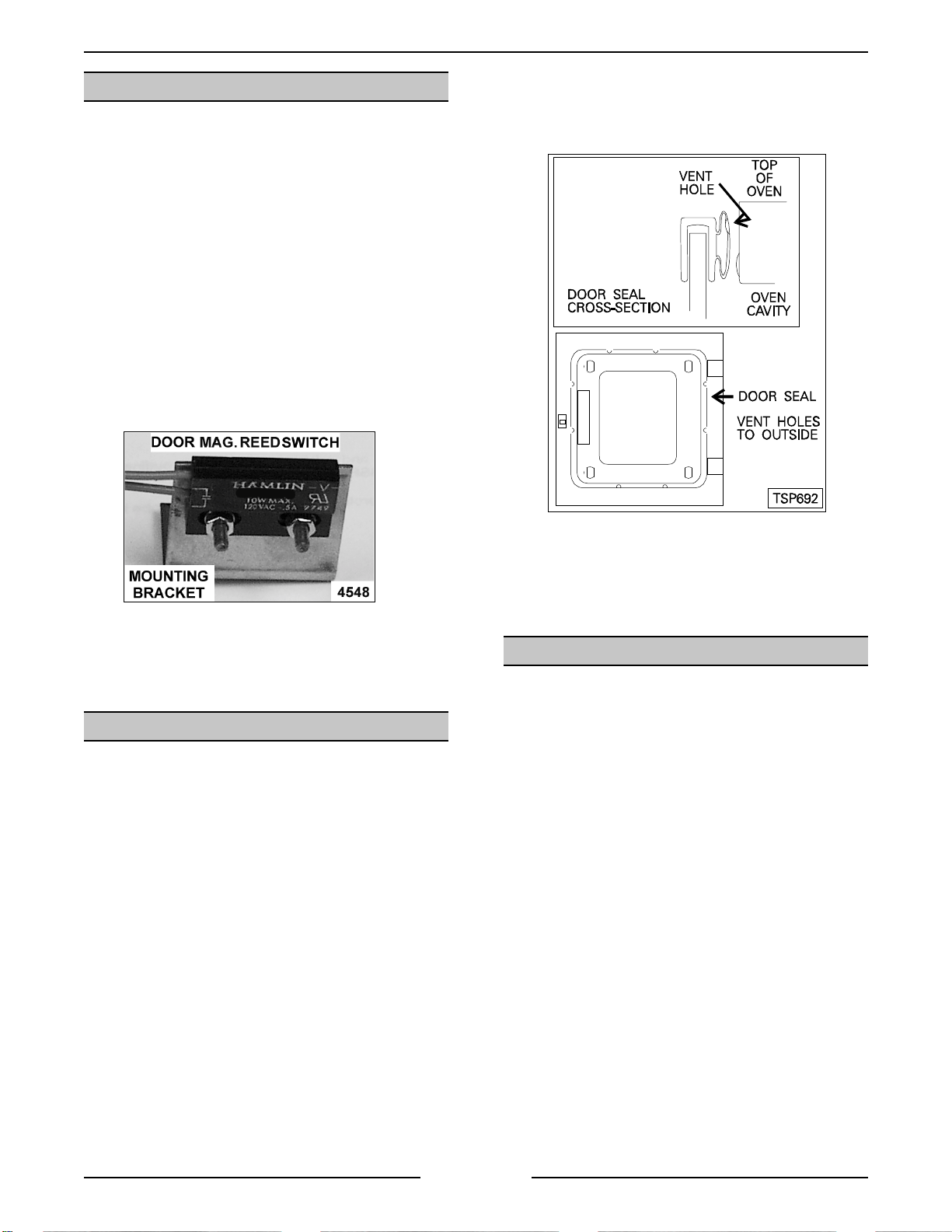
DOOR MAGNETIC REED SWITCH
WARNING:
POWER TO T HE MACHINE AT THE MAIN
CIRCUIT BO X. P LA CE A TAG ON THE CI RCUIT
BOX INDICATING THE CIRCUIT IS BEING
SERVICED.
1. Remove the right side panel as outli ned under
“COVERS AND PANELS”.
2. Remove the nuts that secure the door switch
mounti ng bracket to the bottom of the control
panel. On 20 levels, the switch is m ounted to
the underside of the channel f or the door
handle (no bracket required).
3. Disconnect the switc h lead wires.
4. Remove the switch f rom the oven.
DISCONNECT THE ELECTRICAL
5. Apply red silicone to the repl ac ement seal and
install the seal to the glass edge. The vent
holes must be i nstalled to the outside to all ow
the seal to contract when the door is closed.
6 AND 10 LEVELS
5. Reverse proc edur e to install and c hec k for
proper operati on.
DOOR SEAL
1. Turn the oven off.
2. Open the oven door.
3. Remove seal from the edge of the inside glass.
4. Clean the edge of the glass, rem ove the old
adhesive.
6. Adjust door closure, if nec essary, as outlined
under “OVEN DOOR AND DOOR LOCK
ADJUSTMENT” in “SERVICE PROCEDURES
AND ADJUSTMENTS”.
DOOR LOCKING MECHANISM
WARNING:
POWER TO T HE MACHINE AT THE MAIN
CIRCUIT BO X. P LA CE A TAG ON THE CI RCUIT
BOX INDICATING THE CIRCUIT IS BEING
SERVICED.
Replacement
1. Remove the right side panel as outli ned under
“COVERS AND PANELS”.
2. Disconnect the lead wires to the motor and
switches.
3. Remove the nuts fr om the mounting studs and
remove the assembly from the oven.
DISCONNECT THE ELECTRICAL
Page 20 of 68
Page 21
ELECTRIC COMBI OVEN - REMOVAL AND REPLACEMENT OF PARTS
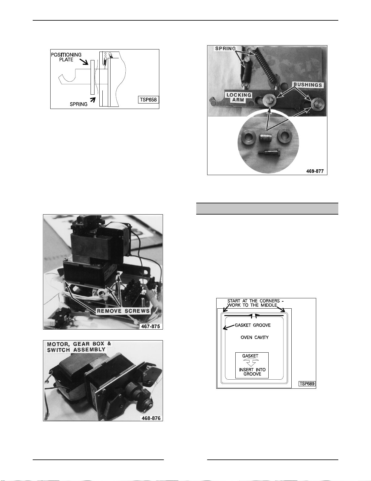
4. Remove the spring and posit ioning plat e from
the locking arm.
5. Reverse proc edur e to install and adjust as
outlined under “O VEN DOOR ADJUSTMENT”
in “SERVICE PROCEDURES AND
ADJUSTMENTS”.
Disassembly
1. Remove the three screws that secure the motor
and switch assembly.
2. Remove the mot or , gear box and switch
assembly from the locking m ec hanism.
Remove the two bolts from the locking
mechanism. The springs, locking arm and
bushings can be removed.
4. The springs, loc k ing arm and bushings can be
removed.
5. Reverse proc edur e to install .
OVEN CAVITY SEAL
3. Remove the two bolts from the locking
mechanism.
1. Open the door.
2. Pull t he seal from the groove around the ov en
cavity.
3. Push the arrow head tip of the gasket int o the
groove. Install the four corners first.
4. Start at the corners and work to the m iddle of
each side, being c ar eful not to stretch the
replacement gasket.
5. Check the door for proper operation and adjust
if nec essary, as outlined under “OVEN DOOR
AND DOOR LOCK A DJ US TMENT” in
“SERVICE PROCEDURES AND
ADJUSTMENTS”.
Page 21 of 68
Page 22

ELECTRIC COMBI OVEN - REMOVAL AND REPLACEMENT OF PARTS
POWER SUPPLY BOARD
AND TRANSFORMER
WARNING:
POWER TO T HE MACHINE AT THE MAIN
CIRCUIT BO X. P LA CE A TAG ON THE CI RCUIT
BOX INDICATING THE CIRCUIT IS BEING
SERVICED.
1. Remove the right side panel as outli ned under
“COVERS AND PANELS”.
2. Disconnect l ead wir e c onnec tions and ribbon
cable f r om the board.
DISCONNECT THE ELECTRICAL
CONTACTORS
WARNING:
POWER TO T HE MACHINE AT THE MAIN
CIRCUIT BO X. P LA CE A TAG ON THE CI RCUIT
BOX INDICATING THE CIRCUIT IS BEING
SERVICED.
1. Remove the right side panel as outli ned under
“COVERS AND PANELS”.
2. Disconnect lead wi r es for the contactor being
replaced.
DISCONNECT THE ELECTRICAL
3. Loosen the two nuts securing the assembly to
the mounting bracket and lift the assembly off
the bracket.
4. Reverse proc edur e to install .
NOTE
: Ensure transf or mer tap wire i s i n the position
that corresponds to the machine data plate voltage.
Refer to the “power supply board and transformer
(1T) “ component on the wiring diagr am for pr oper
connection of the individual lead wires.
3. Remove the jumper bars from the contact or s.
4. Pull t he locking tab out at the contactor base to
release the catc h and r emov e c ontactor f r om
mounti ng bracket.
5. Reverse proc edur e to install .
Page 22 of 68
Page 23

ELECTRIC COMBI OVEN - REMOVAL AND REPLACEMENT OF PARTS
OVEN CAVITY DRAIN
WARNING:
POWER TO T HE MACHINE AT THE MAIN
CIRCUIT BO X. P LA CE A TAG ON THE CI RCUIT
BOX INDICATING THE CIRCUIT IS BEING
SERVICED.
1. Open the oven cav ity door.
2. Lift up the ov en c avity drain grate to remove.
DISCONNECT THE ELECTRICAL
6. Remove the drain vent pi pe from the drain.
7. Disconnect the dr ain cool down water hose
from the drain ni pple extensi on.
8. Unscrew the drain line piping from the bottom
of the oven then remove the oven drain.
9. Reverse proc edur e to install .
3. Unscrew t-bar nut to release drain at the front.
4. Remove rear panel as outlined under
“COVERS AND PANELS”.
5. Disconnect the dr ain pump discharge hose
from the drain vent pipe.
Page 23 of 68
Page 24

ELECTRIC COMBI OVENS - SERVICE PROCEDURES AND ADJUSTMENTS
SERVICE PROCEDURES AND ADJUSTMENTS
WARNING:
MEASUREMENTS WHILE POWER IS APPLIED TO THE MACHINE. EXERCISE EXTREME CAUTION AT ALL
TIMES. IF TEST POI NT S ARE NOT EASI LY ACCESSIBLE, DISCONNECT POWER, ATTACH TEST
EQUIPMENT AND REAPPLY POWER TO TEST .
WARNING:
POWER TO T HE MACHINE AT THE MAIN
CIRCUIT BO X. P LA CE A TAG ON THE CI RCUIT
BOX INDICATING THE CIRCUIT IS BEING
SERVICED.
1. Remove the rear panel as outlined under
“COVERS AND PANELS”.
2. Identify the type of convection fan motor ( s) on
the ov en before setti ng the motor values in
step 9 and 10.
3. Reverse proc edur e to install .
4. Re-connect power to the oven.
The configuration mode can be entered onl y when
the ov en is
mode can be done at any time by pressing the
key to sav e the confi guration settings and exit t he
confi gur ation mode.
To Perf orm:
1. To enter the configurat ion mode press the
TIME, TIME UP
simultaneously for 3 seconds. I n the tim e
display, C and F will be displayed. In the
temperat ure display, “Conf” will be displayed.
2. Press the
DOWN
indicat es t he temperature scale selected. The
control will automatically advance to the next
step, approximately three seconds after the
selection is made. To manually advance to the
next step, pr ess the
3. dSC is displayed in the time display and t he
number of clean cycles complet ed (deliming of
steam generator ) is displayed in t he
temperat ure display.
changed or modified
START/STOP
CERTAIN PROCEDURES IN THIS SECTION REQUIRE ELECTRICAL TEST OR
CONFIGURATION MODE -
PROGRAMABLE CONTROL
DISCONNECT THE ELECTRICAL
OFF
. Returning to the normal operating
TIME DOWN
and
TIME UP
key for Celsius. The blinking letter
key for Fahrenheit or
START/STOP
The number cannot be
. Press the
key to advance to the next step.
keys
key.
OFF
TIME
4. The EPROM r evisi on level is displayed in the
tim e display and “Conf” is displayed in the
temperat ure display. T o veri fy the EPROM is at
the current r evisi on level, ref er to the Technic al
Service Bulletins. Press the
to adv anc e to the next step.
5. HHH is displayed in the time display and the
total cook ing hours of the oven is di spl ay ed in
the temper ature display. P r ess the
key to increase number of hour s or t he
DOWN
the current number of hour s i s acceptable,
press
step.
NOTE
not changed withi n 3 seconds, t he c ontrol will
automatically advance to the next step wit hout
pressing the
6. bbb flashes and is di spl ay ed in the time
display, the frequency number is display ed in
the temper ature display and t he buz z er shoul d
be sounding. Press the
DOWN
continuous and 255 = very slow int er vals)
number. A good setting to start with is 050 or
any number that is prefer able to the customer.
If t he setting is accept able, press the
START/STOP
7. uuu is displayed in the time display and the
steam temperature setting is displayed i n the
temperat ure display. T he steam temper ature
setting is t he boiling point adjustm ent for
elevation and m ust
results. Press the
number or
number. Set the temper ature according to the
table below. P r ess the
advance to the next step.
key to decrease the number of hours. If
START/STOP
: If a c onfigurat ion parameter is selected and
START/STOP
keys to set the buzzer frequency (000 =
TEMP DOWN
START/STOP
TEMP UP
key to advance to the next
key.
TEMP UP
key to advance to the next step.
be set to achieve optimum
TEMP UP
key to decrease
START/STOP
or
key to increase
key
TEMP
TEMP
key to
Page 24 of 68
Page 25

ELECTRIC COMBI OVENS - SERVICE PROCEDURES AND ADJUSTMENTS
: The temperature select ed in the table below
NOTE
will also be the highest starting point temperature
available, when the steam mode i s selected.
ELEVATION
(FT)
Sea level to 500 212
500 to 1000 211
1,000 to 2,000 209
2,000 to 3,000 207
3,000 to 4,000 205
4,000 to 5,000 204
5,000 to 6,000 202
6,000 to 7,000 200
7,000 to 8,000 198
8,000 to 9,000 196
9,000 to 10,000 195
Above 10,000 194
TEMPERATURE
(°F)
8. CCC is displayed in the time display and the
convec tion tem perature li mit is displayed in the
temperat ure display. Pr ess the
TEMP UP
key
to increase number (482°F to 518°F) and
TEMP DOWN
key to decrease num ber . Set the
temperat ure to read 518°F. Pre ss the
START/STOP
key to advance to the next step.
9. 1 - - is display ed in the time display and t he
minimum
value for the c onvection fan motor is
displayed i n the temperat ur e display. Press the
TEMP UP
DOWN
to Position 1
the v alue is correct , press the
key to increase number and
TEMP
key to decrease num ber . Set accordi ng
(minimum) in the table below. If
START/STOP
key to advance to the next step.
10. 2 - - is displayed in the time display and a
maximum
value for the c onvection fan motor is
displayed i n the temperat ur e display. Press the
TEMP UP
TEMP DOWN
according to Position 2
key to increase number and the
key to decrease num ber . Set
(max imum) in the table
below. If the value is correct, press the
START/STOP
key to advance to the next step.
CONVECTION FAN MOTOR
CONVECTION FAN
MOTOR TYPE
1 motor Leroy-Somer
(Hanning)
1 motor Brook-Crompton
2 motors Leroy-So mer
(Hanning)
2 motors Brook-Crompton 30 90
1 motor Leroy-Somer
(Hanning) and 1 motor
Brook-Crompton
: (*) Ove n s are shipped from the factory with th is
NOTE
motor and the oven control is configured
accordingly.
The values correspond to th e current limits only
and are not the actual current draw of the motor.
POSITION 1
(MINIMUM)
*
VALUE
POSITION 2
(MAXIMUM)
855
860
46 120
38 105
11. If all t he values have been entered corr ectly,
press the
key to sav e the confi guration
OFF
settings and exit the configuration mode. To
review or change a configuration value press
the
START/STOP
key to return to step 1.
DIAGNOSTIC TEST MODE -
PROGRAMABLE CONTROL
The test mode can be entered only when the oven is
The five t ests are r un in sequence (1 - 5) and
OFF.
are indicated by the position of the illuminated LED
in the bar graph of the com bi mode key.
The test are performed in a fixed sequence of:
1. ROM (automatical ly)
2. RAM (autom atically)
3. Displays and LED’s
4. Relays (relay on for max. of 2 seconds)
5. Keypad
To Perf orm:
1. To enter the t est mode press the
UP
and
TEMP DOWN
keys simul taneously for
3 seconds. The word “test” will be displayed in
the temper ature display.
TEMP, TEMP
2. If a RO M or RA M error is detect ed, a error
Page 25 of 68
code (01 = ROM and 02 = RAM) will be
displayed on the temperature display and will
repeat until a key is pushed to ex it this test. If
no errors are detected, the control advances to
the next test and runs it automatically.
Page 26

ELECTRIC COMBI OVENS - SERVICE PROCEDURES AND ADJUSTMENTS
3. The DISPLAY and LE D test consists of flashing
all di splays and LED’s. The word “test” will flash
intermittent ly as the tem per ature display i s
tested. Verify all the DI SPLAYS and LED’s a re
flashing. This test will continue until a key is
pressed to advance to the next step.
4. The RELAY test consi st of selecting a
particular relay by its code number (01 to 11)
with the
TEMP UP
and
TEMP DOWN
keys.
The initial code displayed in the temperature
display i s 01 for relay K1. Press the
TEMP
key
to energize t he selected relay for a maxim um
of 2 seconds. Verify that each selected rel ay
(K1 to K10) is functi oning. See tabl e below. To
exit this test and proceed to the next, pr ess the
key.
OFF
CODE RELAY COMPONENT
01 K1 door mo tor
02 K2 cavity vent motor
03
*
04 K3 cooling fan(s) and door light only
05 K3, K4 water inje ction so lenoid (humidifier)
06 K5 drain pump
07 K3, K5 water fill solenoid
08
*
09
*
10
*
11
*
NOTE
engaged. No noticeable external component o p erates.
K6 contactor KM1 (ha lf power, full speed)
K7
K8
K10
K9
: Asterisk (*) indicates relay is checked but contactor not
contactor KM2 (half power, ha lf speed);
on 20 levels only, contactor KM3 and
drain cool do wn solenoid.
contactor KM3 and drain cool down
solenoid on 6 & 10 levels;
contactor KM5 on 20 levels only
(steam generator heating elements)
contactor KM7
(convection heating elements)
contactor KM6
(convection heating elements)
5. The keypad test consi st of pressing each key to
check its functionality. Initially, 02 is displayed
in the time display and “test” is displayed in the
temperat ure display. With each successful key
press, the number of the key i s di spl ay ed in
the time display. Each key is number ed,
starting wit h number 01 (ON) in the upper left
corner of the control and ends at 21
(humidifi er) on the lower right corner. See table
below. Verify that all keypad buttons are
functioning properly.
KEY NO. KEY NO.
ON 01 TEMP 12
OFF 02 TEMP DOWN 13
HOT AIR 03 TEMP UP 14
STEAM 04 DELTA T 15
COMBI 05 PROG 16
START/STOP 06 ENTER 17
PHASE 07 ENTER DOWN 18
TIME 08 ENTER UP 19
TIME DOWN 09 FAN SPEED 20
TIME UP 10 HUMIDIFIER 21
PROBE 11
6. To exi t the diagnosti c test mode, press and
hold the
key for approximately 3 seconds.
OFF
CONFIGURATION MODE -
MANUAL CONTROL S
WARNING:
POWER TO T HE MACHINE AT THE MAIN
CIRCUIT BO X. P LA CE A TAG ON THE CI RCUIT
BOX INDICATING THE CIRCUIT IS BEING
SERVICED.
1. Remove the rear panel as outlined under
“COVERS AND PANELS”.
2. Identify the type of convection fan motor ( s) on
the ov en before setti ng the motor values in
step 9 and 10.
3. Reverse proc edur e to install .
4. Re-connect power to the oven.
The configuration mode can be entered onl y when
the ov en is
mode can be done at any time by pressing the
START
exit the confi gur ation mode.
To Perf orm:
1. To enter the configurat ion mode press the
TIME
seconds. In the temperature display , “Conf” will
be displayed. P r ess the
to the next step.
2. C and F will be displayed in the time display.
Rotate the adj ustment knob counterclockwise
for Cel sius and clockwise for Fahrenheit. The
blinking letter indicates the temperature scale
selected. Ac c ept the selecti on by pr essing t he
TIME
DISCONNECT THE ELECTRICAL
. Returning to the normal operating
OFF
key to sav e the confi guration settings and
and
TEMP
keys simul taneously for 3
key to advance
TIME
key to advance to the next step.
Page 26 of 68
Page 27

ELECTRIC COMBI OVENS - SERVICE PROCEDURES AND ADJUSTMENTS
3. dSCL is displayed in the time display and t he
number of clean cycles complet ed (deliming of
steam generator ) is displayed in t he
temperat ure display.
changed or modified
The number cannot be
. Press the
TIME
key to
advance to the next step.
4. The EPROM r evisi on level is displayed in the
tim e display and “Conf” is displayed in the
temperat ure display. T o veri fy the EPROM is at
the current r evisi on level, ref er to the latest
Technical Service Bulletins
. Press the
TIME
key to advance to the next step.
5. HHHH is displayed i n the tim e display and the
total cook ing hours of the oven is di spl ay ed in
the temper ature display. Rotate the adjustment
knob counterclockwise
hours and clockwise
to decrease number of
to increase number of
hours. If the current number of hours is
acceptable, press the
key to advance to
TIME
the next step.
6. bbbb flashes and is di spl ay ed in the
TIME
display, the frequency number is display ed in
the temper ature display and t he buz z er shoul d
be sounding. Rotate t he adjustment k nob
counterclockwise
and clockwise
to decrease buzzer frequency
to increase buzzer frequency
(000 = continuous and 255 = very slow
intervals) number. A good setti ng to start with is
050 or any number that is pref er able to the
customer. If the sett ing is acceptabl e, press the
key to advance to the next step.
TIME
7. uuuu is displayed in the time display and the
steam temperature setting is displayed i n the
temperat ure display. T he steam temper ature
setting is t he boiling point adjustm ent for
elevation and m ust
be set to achieve optimum
results. Rotat e the adjustment k nob
counterclockwise
to decrease and clock wise to
increase. Set the temperat ur e ac c or ding to the
table below. P r ess the
key to advance to
TIME
the next step.
: The steam temperatur e setting
NOTE
will also be
the initial cavit y set point tem per ature and the
maximum c avity temperature that can be set, when
the steam mode is selected.
ELEVATION
(FT)
Sea level to 500 212
500 to 1000 211
1,000 to 2,000 209
2,000 to 3,000 207
3,000 to 4,000 205
4,000 to 5,000 204
5,000 to 6,000 202
6,000 to 7,000 200
7,000 to 8,000 198
8,000 to 9,000 196
9,000 to 10,000 195
Above 10,000 194
TEMPERATURE
(°F)
8. CCCC is displayed i n the tim e display and the
convec tion tem perature li mit is displayed in the
temperat ure display. Rot ate the adjustm ent
knob counterclockwise
518°F) and cloc k wise
the temper ature to read 518°F. P r ess the
to decrease (482°F to
to increase number. Set
TIME
key to advance to the next step.
9. 1 - - is display ed in the time display and t he
minimum
value for the c onvection fan motor is
displayed i n the temperat ur e display. Rotat e
the adjustm ent knob counterclockwise
decrease and clockwise
Set according to Position 1
to increase number.
(minimum) in the
to
table below. If the value i s cor r ec t, press the
key to advance to the next step.
TIME
10. 2 - - is displayed in the time display and a
maximum
value for the c onvection fan motor is
displayed i n the temperat ur e display. Rotat e
the adjustm ent knob counterclockwise
decrease and clockwise
Set according to Position 2
to increase number.
(max imum) in the
to
table below. If the value i s cor r ec t, press the
key to advance to the next step.
TIME
Page 27 of 68
Page 28

ELECTRIC COMBI OVENS - SERVICE PROCEDURES AND ADJUSTMENTS
CONVECTION FAN MOTOR
CONVECTION FAN
MOTOR TYPE
1 motor Leroy-Somer
(Hanning)
1 motor Brook-Crompton
2 motors Leroy-So mer
(Hanning)
2 motors Brook-Crompt on 30 90
1 motor Leroy-Somer
(Hanning) and 1 motor
Brook-Crompton
: (*) Ove n s are shipped from the factory with th is
NOTE
motor and the oven control is configured
accordingly.
The values correspond to th e current limits only
and are not the actual current draw of the motor.
POSITION 1
(MINIMUM)
*
VALUE
POSITION 2
(MAXIMUM)
855
860
46 120
38 105
11. If all t he values have been entered corr ectly,
press the
START
key to sav e the confi guration
settings and exit the configuration mode. To
review or change a configuration value press
the
key to return to step 1.
TIME
With each successful sel ec tion, the
corresponding num ber is displayed in t he
temperat ure display. F or the adjustment k nob,
an upper or lower dash line will be displayed
(depending on rotation). See t able below.
Verify that all knob positi ons and keypad
buttons are func tioning proper ly. When
satisfied, press and hold the
START
key for 4
seconds to advance to the next step.
SWITCH/ KEYPAD/KNOB POSITION NO./DASH
SELECTOR SWITCH OFF 0
SELECTOR SWITCH HOT AIR 1
SELECTOR SWITCH STEAM 2
SELECTOR SWITCH COMBI 3
SELECTOR SWITCH COOL DOWN 4
SELECTOR SWITCH DE-SCALE 5
KEYPAD BUTTON TIME 6
KEYPAD BUTTON PROBE 7*
KEYPAD BUTTON TEMP 8
LINE
DIAGNOSTIC TEST MODE -
MANUAL CONTROL S
The test mode can be entered only when the oven is
OFF.
The test are performed in a fixed sequence of:
1. Displays and LED’s
2. Selector swit c h, keypad and adjustm ent knob.
3. Relays (relay on for max. of 2 seconds).
To Perf orm:
1. To enter the t est mode press the
keys simul taneously for 4 seconds.
TEMP
START
2. The DISPLAY and LE D test consists of flashing
all di splays and LED’s while the buzzer sounds.
In the temperature displ ay , all the individual
display segments and the word “test” will flash
intermittent ly. Verify al l the displays and LED’s
are flashing. This test will continue until the
START
key is pressed and held f or 1 second t o
advance to the next step.
3. The word “test” is displayed in the temperature
display and 10 (start button keypad no.) is
displayed i n the “time” display. The KEYPAD
test consists of r otating the selec tor switch
clockwise
through each position, pressing each
button on the keypad and r otating the
adjustment knob clockwise
counterclockwise
to check the functionality of
then
each.
and
KEYPAD BUTTON DOOR 9
KEYPAD BUTTON START 10
KEYPAD BUTTON COMBI 12*
KEYPAD BUTTON VENT 13*
ADJUSTMENT KNOB ROTATE CW
ADJUSTMENT KNOB ROTATE CCW
: Asterisk (*) indicates not ava ilable on standard
NOTE
manua l controls.
“—“
4. The word “test” will still be displayed in the
temperat ur e display. The RE LA Y test consist of
selecting a par ticular r elay by its code number
(01 to 11) with t he adjustment knob and
pressing the
key to energize the relay
TEMP
for a maximum of 2 seconds. See table below.
Verify that each selec ted relay (K1 t o K 10) is
functioning. The status of the relay output (0 or
1) will be displayed in the left side of the
temperat ure display. When satisfied, press and
hold the
START
key for 1 second to advance
to the next step.
“—“
Page 28 of 68
Page 29

ELECTRIC COMBI OVENS - SERVICE PROCEDURES AND ADJUSTMENTS
CODE RELAY COMPONENT TEST CONDITION
Door magnetic reed switch. Result will be displayed
01 K1 door motor
02 K2 cavity vent motor
03 K3, K6 contactor KM1 (half power, full speed)
04 K3 cooling fan(s) and door light only
05 K3, K4 water injection solenoid (humidifier) Visual - water injection into cavity.
06 K5 drain pump Water level sensors (water level in steam generator)
07 K3, K5 water fill solenoid Water level sensors (wa ter level in steam generator)
contactor KM2 (half power, ha lf speed);
08 K3, K7
09 K3, K8
10 K3, K10
11 K3, K9
on 20 levels only, contactor KM3 and
drain cool do wn solenoid.
contactor KM3 and drain cool down
solenoid on 6 & 10 leve ls; contactor
KM5 on 20 levels only.
(steam generator heating elements)
contactor KM7 (convection heating
elements on 10 & 20 levels)
contactor KM6
(convection heating elements)
automatically. Rotate the door handle to change the
condition. Press and hold the TEMP key to close the
door; release to open.
Cavity vent micro switch. Result will be displayed
automatically. Press and hold the TEMP key to
change condition.
Convection fan motor value - press and hold the
TEMP key for 30 sec. to test the fan motor
configuration settings. The test result will be
displayed .
Cavity Hi Limits and steam generator thermal
fuse(s). Press and h old the TEMP key for result.
0 = open;
1 = closed
0 = open;
1 = closed
0 = incorrect;
1 = correct.
0 = open;
1 = closed
0 = unsatisfied;
1 = satisfied
5. t1 is display ed in the time display and t he ac tual cavity t emperature i s di splayed in the temperature di spl ay .
Verify the probes are sensing tem per ature correctly. Rotate t he adjustment knob and select the probe
temperat ure to display (T1 = cavity probe (top on 20 levels); T2 = bottom cavit y pr obe ( 20 levels only); T3 =
cooking probe).
6. To exi t the diagnostic test mode, pr ess and hold t he
SERVICE ERROR LIGHTS
1. There are f our lights at the bottom of the
control. When l it, they tell the operator that t he
oven needs service related to the component
that the l ight(s) represent. Refer to
“TROUBLESHOOTING” for display error
codes.
START
key for approximately 3 seconds.
: If the steam generator thermal fuse(s) or the
NOTE
cavity high limits open, the steam gener ator heat
and the convection heat er ror light s will come on.
2. Turn the oven off and reset the oven control .
A. P r ogrammable control - pr ess the off key.
B. M anual controls - r otate the selector switc h
to the of f positi on.
3. Correct the pr oblem rel ated to the service error
light. See “TROUBLESHOOTING” section.
4. Turn the oven on and check operation.
A. P r ogrammable control - pr ess the on key,
select a heating mode and press start key
to begin.
The lights are, from left to right.
A. Water suppl y.
B. Convection heat.
C. Steam gener ator heat.
D. Cavity f an.
B. M anual controls - r otate the selector switc h
to one of t he three heating modes.
: On water supply err or s, monitor the oven for
NOTE
at least 5 m inutes to pass the “time out” period for
the steam generator fill.
Page 29 of 68
Page 30

ELECTRIC COMBI OVENS - SERVICE PROCEDURES AND ADJUSTMENTS
HEATING ELEMENTS
WARNING:
POW E R TO BE APPLIED TO THE UNI T DURING
THE TEST. USE EXTREME CAUTION AT ALL
TIMES.
1. Measure the voltage at the heating element
terminals and verify it against t he data plate
voltage.
A. If voltage is incorrect, find the sourc e of
2. If volt age is correct, c hec k c ur r ent draw (amps)
through the heating element lead wires. If
current draw is correc t then heating element i s
ok.
A. If current draw is not correct then, replace
3. Check for proper operation.
MODEL VOLTAGE
VCE6H
VCE10H
VCE20F
VCE20H
NOTE
MODEL VOLTAGE
VCE6H
VCE10H
VCE20F
VCE20H
NOTE
THE FOLLOWI NG ST EPS REQUIRE
the problem.
See table below for p roper values.
heating element.
CONVECTION HEAT
KW PER
ELEMENT
208 9 15 14
240 9 13 19
480 9 11 26
208 6 10 22
240 6 8 29
480 6 7 38
Values in the table are nom i n al. Tolera nce is
:
+5/-10 %.
STEAM GENERATOR HEAT
KW PER
ELEMENT
208 8 13 16
240 8 11 22
480 8 10 29
Values in the table are nom i n al. Tolera nce is
:
+5/-10 %.
AMPS PER
ELEMENT
LEAD
(3 PH)
AMPS PER
ELEMENT
LEAD
(3 PH)
OHMS PER
ELEMENT
OHMS PER
ELEMENT
OVEN DOOR ADJUSTMENT
NOTE
: Follow the steps in the order outlined below
for proper door adjustment .
1. Turn the oven off.
2. Check the level of the oven from lef t to right
and front to back, in t he exact loc ation where
the ov en is to be positioned.
A. If the oven is not
necessary adjustment s before proceeding
to the next step.
B. If the oven is level, then proceed to step 3.
3. Loosen the hinge screws just enough to adjust
the door position but so the door stays when
not being m oved or supported.
4. Position the door square with the oven as
shown below.
5. Tighten t he hinge screws after adjusting.
WARNING:
DISCONNECT THE ELECTRICAL
POWER TO T HE MACHINE AT THE MAIN
CIRCUIT BO X. P LA CE A TAG ON THE CI RCUIT
BOX INDICATING THE CIRCUIT IS BEING
SERVICED.
6. Remove the right side panel and the contr ol
panel as outlined under ”COVERS AND
PANELS”.
7. Loosen the screws on the door roller (str iker)
just enough to adjust its position but stay s when
not being m oved.
level, make the
Page 30 of 68
Page 31

ELECTRIC COMBI OVENS - SERVICE PROCEDURES AND ADJUSTMENTS
8. Position the door roller against the “striking”
edge of the locking arm but do not close t he
door.
A. Observe the posi tion of the door roll er to
the locking arm.
B. A djust the door rol ler so it m ates at the
“striki ng edge” ( bottom of the sloped edge)
of the locking arm. The exac t distance of
the “striking” edge to the bottom of the
roller is stated to be 1 mm (0.040 inches).
This position allows the locking arm to be
pushed down during closing, and after
closing the roller will be positioned in the
hook.
10. With t he door in the closed posit ion the roller
should be cradled in the locking arm hook.
11. Replace the control panel.
12. Close the door handle. The handl e is centered
in the cut- out of the control panel so the
magnet i n the handle will operate the m agnetic
reed switch.
1) If the door roller mates against the
locking arm as described, t hen
tighten t he door roller screws and
proceed to step 9.
2) If the rol ler does not mate against the
locking arm as described and there is
no more adjust ment in t he door r oller,
then loosen the bolts securing the
door motor assem bly and adjust the
locking arm position as described.
3) The door roller should now m ate
against the locking arm pr oper ly.
Tighten t he bolts securing the door
motor assembly and proceed to
step 9.
9. Push the door closed and observe the locking
arm. I t must not contact the bottom edge of t he
slot that t he locking arm travels in whil e the
door is closing.
NOTE:
adjustable if necessary. Remove t he br ac k et from
the bottom of the control panel. Loosen the hex nuts
securing the switch t o the bracket and position the
switch (left to ri ght) where desired. Tighten hex nuts
and replace brack et. Check switch for proper
operation.
WARNING:
POW E R TO BE APPLIED TO THE UNI T DURING
THE ADJUSTMENT. USE EXTREME CAUTION AT
ALL TIMES.
13. Turn t he oven on.
14. The door shoul d automati c ally pull shut and
15. The space between the t op inner edge of t he
The magnetic reed switch position is
THE FOLLOWI NG ST EPS REQUIRE
lock into position t o seal the oven opening.
door and the oven should be equal along its
length.
16. Thi s space can be adjusted by adding or
NOTE
motor assembly mounting bolts.
Page 31 of 68
removing shims from the door hinges or the
door locking mechanism.
: Ext r a shims are provided under the door
Page 32

ELECTRIC COMBI OVENS - SERVICE PROCEDURES AND ADJUSTMENTS
A. If the space i s l arger at the hinge end,
remove shim( s) from behind the hinges or
from in fr ont of the door locking
mechanism.
B. If the space i s sm aller at t he hinge end,
add shim(s) behi nd the hinges or in front
of the door locking mechanism.
: If shi ms are removed f r om the top hi nge,
NOTE
also remove them from the top hinge.
17. If the space is equal, but the ov en does not
seal. Remove shims from the hinges and in
front of the door l oc king mechanism.
18. Once t he nec essary adjustments have been
made and the door is closing properl y , replace
the right side panel and turn the oven of f.
BUZZER ADJUSTMENT -
PROGRAMABLE CONTROL
To properly set the buzzer, both t he frequency and
volume
results. These adjustments are independent of each
other and requir e a c onfigurat ion mode change and
a manual adjustment of the tri m pot.
WARNING:
POW E R TO BE APPLIED TO THE UNI T DURING
THE ADJUSTMENT. USE EXTREME CAUTION AT
ALL TIMES.
1. Remove the right side panel as outli ned under
2. Place the control into configuration m ode as
must be adjusted to obtain the best audible
THE FOLLOWI NG ST EPS REQUIRE
“COVERS AND PANELS” in “REMOVAL AND
REPLACEMENT OF PARTS”.
outlined under “PROG RAMABLE CONTROL CONFIGURA TION MODE”.
4. To adjust the buz z er volume, turn t he buz z er
volume adjustment screw until the desired
volume is obtained.
5. Once the buzzer frequency and volume are set
to the desired level s, pr ess the
save the sett ing and exit the configuration
mode.
OFF
key to
BUZZER ADJUSTMENT -
MANUAL CONTROL S
To properly set the buzzer, both t he frequency and
volume
results. These adjustments are independent of each
other and requir e a c onfigurat ion mode change and
a manual adjustment of the tri m pot.
WARNING:
POW E R TO BE APPLIED TO THE UNI T DURING
THE ADJUSTMENT. USE EXTREME CAUTION AT
ALL TIMES.
must be adjusted to obtain the best audible
THE FOLLOWI NG ST EPS REQUIRE
A. Press the
through the configuration parameter s until
reaching the step for setti ng the buzzer
frequency.
B. To adjust the buzzer frequency, foll ow the
procedure as outlined in step 6 under
“PROGRAMABLE CONTROL CONFIGURA TION MODE”.
3. After the buzzer frequency is set to the desir ed
level, press the
through the configuration parameter s agai n,
until r eaching the step for setting the buz z er
frequency.
START/STOP
START/STOP
key to cycle
key to cycle
Page 32 of 68
1. Remove the right side panel as outli ned under
“COVERS AND PANELS” in “REMOVAL AND
REPLACEMENT OF PARTS”.
2. Place the control into configuration m ode as
outlined under “M A NUA L CONTROLS CONFIGURA TION MODE”.
A. Press the
confi gur ation param eters until reac hing
the step for setting the buzzer frequency.
B. To adjust the buzzer frequency, foll ow the
procedure as outlined in step 6 under
“MANUAL CONTRO LS CONFIGURA TION MODE”.
3. After the buzzer frequency is set to the desir ed
level, press the
confi gur ation param eters again, unti l reaching
the step for setting the buzzer frequency.
key to cycle through the
TIME
key to cycle through the
TIME
Page 33

ELECTRIC COMBI OVENS - SERVICE PROCEDURES AND ADJUSTMENTS
4. To adjust the buzzer volume, turn the buzzer
volume adjustment screw until the desired
volume is obtained.
5. Once the buzzer frequency and volume are set
to the desired level s, pr ess the
save the sett ing and exit the configuration
mode.
START
key to
CLEAN CYCLE MODE - STEAM
GENERATOR DELIMING
WARNING:
HOT. USE CARE WHEN OPERATING, CLEANING
OR SERVICING THE OVEN. THE COOKING
COMPARTMENT CONTAINS LIVE STEAM. STAY
CLEAR WHEN OPENING DOOR.
Steam generator deliming should be done on a
scheduled basis. The frequency depends on the
quality of the loc al water supply and whether or not
a water treatment system is used. Even with the use
of a water tr eatment system , periodic deliming of
the steam generator is still required.
On combi ovens using a water t r eatment system ,
follow the instructions for that system to deli me the
steam generator . Only use the ty pe of chemical
recommended or described in the deliming
instructions for the system in use. If the Kleensteam
water treatment system is used, Scalekleen is the
recommended chemi c al.
If a water t reatment system is not
instructions for deliming the steam generator usi ng
vinegar, as outli ned in the steps below. See
“WA TER CONDITI ONING” under “GENERAL”.
THE OVEN AND ITS PARTS ARE
used, follow the
1. Programmable oven control
to turn the oven on and press the
enter the programed cooking mode. Program
number “00" is displayed in t he pr ogr am
display. P r ess the down key once, to select the
clean cycle program or if at program 98 press
the up key once to select the clean cycle
program. Press and hold for automatic
scrolling. “CC” is displayed in the program
number display and “dSCL” is displayed in the
temperat ure display. Pr ess the
key to start the clean cycl e and the start/stop
LED turns on.
Manual oven controls
select the descal e mode by rotating the
selector knob to dS CL. “dSCL” is displayed in
the temperat ure display and the clean cycle
starts automatically.
2. The steam generator begins a normal drain
cycle.
A. At the end of the drai n cycle, ov en beeps
for 10 seconds. On the programmable
oven control, the star t/stop LED turns of f.
B. “40" minutes is di spl ay ed in the time
display and “dSCL” is displayed in the
temperat ure display.
3. Add the deli ming chemical.
A. If a water treatment system is installed in
the water li ne to the steam generat or .
1) Tur n the water supply off.
2) Press the relief valve at the top of the
feeder bowl head to relieve system
pressure.
3) Unscrew the feeder bowl (clear) from
the head and remove cartridge from
the bowl.
4) Remove t he dip from its holding clip
and insert the dip tube (o-ring first) in
to the center port.
5) Add t he appr opriate am ount of
deliming chemical to the feeder bowl
for the c ombi m odel and mi x the
contents of the bowl with water. See
table below.
: Do not
NOTE
amounts listed in the table below or
provided with the delimi ng c hemical for
the water treatment system in use.
6) Repl ac e the feeder bowl.
7) Tur n the water supply on.
exceed the chemical
- Press the ON key
key to
PROG
START/STOP
- Turn the oven on and
Page 33 of 68
Page 34

ELECTRIC COMBI OVENS - SERVICE PROCEDURES AND ADJUSTMENTS
B. If there is no water treatm ent system
installed in the water line to the steam
generator, then add an amount of vinegar
equal
to the tank volume for the combi
model. S ee table below.
1) Add t he vinegar to the steam
generator through the opening in the
oven cavity. Use the funnel and
flexible tube provided with the oven.
TANK
MODEL
VCE6H
VCE10H
VCE10F
VCE20H
VCE20F
NOTES
VOLUME
(GAL) (QT)
0.8 3.2 1.0 Packet or 7.0 oz.
1.6 6.3 1.5 Packets or 10.5 oz.
1.6 6.3 1.5 Packets or 10.5 oz.
2.6 10.5 2.5 Packets or 17.5 oz.
3.4 13.7 3.5 Packets or 24.5 oz.
: 1. Scalekleen is also available in a 2.2 lb packet
size. If the 2.2 lb. size is used, do
entire packet. Measure the appropriate amount
in ounces then add.
2. Do no t exceed the a mounts listed in the table
above.
AMOUNT OF
SCALEKLEEN ADDED
TO FEEDER BOWL
(7 OZ. PACKET SIZE)
add the
not
1, 2
4. Press the START but ton on the ov en c ontrol
(programmable or manual) to begi n the clean
cycle.
A. The door closes and locks and the
buttons/knobs on keypad l oc k out to
prevent interruption until the clean cycle is
completed. No other operations can be
performed for approximately 45 minutes.
: Pressing the off key will not discontinue
NOTE
the clean cycle or t urn the oven off. If a power
interruption or other malf unc tion occurs, the
clean cycle will resume from step 5B when
power is restored.
B. If deliming through a water treatment
system, the steam generator begi ns a
normal fill cycle.
1) When the proper water level is
reached, the steam generator heating
element s and cavit y fans turn on.
C. If deliming using v inegar, the amount
added to the steam generator is already at
the proper level.
1) The steam generator heat ing
element s and cavit y fans turn on.
2) As the vinegar level lowers, the
steam generator will then f ill with
water as required.
: If the cavity temperature is above the
NOTE
steam temperature set point, automatic cooling
will occur. See “WATER INJECTION
(HUMIDIFIER) under SEQUENCE OF
OPERATION”.
D. The timer starts counting down and the
oven will steam for 30 minutes.
5. At the end of 30 minut es.
A. Heating elements and cavity f ans tur n off.
: Heating elements and cavity fans
NOTE
remain off dur ing “timed” drain and fill cycles.
B. Time display shows 10 minutes but does
not continue c ounting down.
C. Steam gener ator drains (45 seconds on 6
& 10 levels; 60 seconds on 20 levels).
D. Steam gener ator fills (37 seconds on 6 &
10 levels; 75 seconds on 20 levels).
6. The steam generator drains twice more and fills
once (both ti med) to rinse out any remai ning
chemicals.
7. The steam generator begins a normal fill cycle.
A. When the pr oper water level is reached,
the heating elements and cavity fans turn
on.
B. The tim er st ar ts counting down and the
oven will steam for 10 minutes.
8. When time expires, the steam generator drains
a final time.
9. At the end of the clean cycle procedure.
A. The oven will beep for 10 seconds and the
temperature display will show “dOnE”
indicating the cycle is complete.
B. The door unlocks and opens (slightly) and
the buttons/knobs on keypad unlock.
NOTE:
If an error occurs during the clean cycle,
“FAIL” will display in the temperature display instead
of “dOnE”.
C. If a deliming chemi c al was added to the
water treatment system.
1) Tur n the water supply off.
2) Press the relief valve at the top of the
feeder bowl head to relieve system
pressure.
3) Unscrew the feeder bowl from the
head, remove the di p tube and reinstall the cartridge.
4) Repl ac e the feeder bowl.
5) Tur n the water supply on.
D. If vinegar was added to the steam
generator, then procedure is complete.
10. Combi oven is ready for normal use.
Page 34 of 68
Page 35

ELECTRIC COMBI OVENS - SERVICE PROCEDURES AND ADJUSTMENTS
BATTERY BACKUP -
PROGRAMABLE CONTROL
The battery backup module allows the SRAM (static
ram) to retain the configurat ion and program
infor mation in memory if there is a power loss. The
battery backup may com e in a two piece
confi gur ation of an S R A M c hip mounted ont o a
battery module or a one piec e S RA M and battery
module combination. The 28 pin non- volatile
SRAM/Battery modul e is located on the CPU board.
Unless power to the ov en is interrupted and then
restored, a low voltage bat tery condition would
otherwise not be detect ed.
1) Press the key pad ON button. If
dashes “- - -“ are displayed in the
time
display and
the temper ature display, then battery
module volt age may be low.
WARNING:
POWER TO T HE MACHINE AT THE MAIN
CIRCUIT BO X. P LA CE A TAG ON THE CI RCUIT
BOX INDICATING THE CIRCUIT IS BEING
SERVICED.
DISCONNECT THE ELECTRICAL
2) Remove t he r ight side panel as
outlined under “COVERS AND
PANELS”
With the power disconnected from
3)
the oven
voltage while m ounted on the CPU
board. Measure the voltage between
pins 14 and 28 on the SRAM chip. If
voltage is less than 3VDC, t hen
replace the SR A M /Battery module
combination (one or two piec e) as
outlined below in “BATTERY
REPLACEMENT” and repeat battery
test.
, check the bat tery module
888c
is displayed in
Battery Test
1. Disconnect power f r om the oven, then turn the
power back on.
2. The control board will perform a power up
diagnostic test, sound the buzzer and turn the
displays and lights on then off.
A. If the displays go blank and lights turn of f
on the control , then the battery backup is
functioning properly.
B. If oven or control will not power up, see
“TROUBLESHOOTING” section for a list
of possible c auses.
C. If c ode numbers appear in the t ime and
temperat ure display or the c ontrol
operation i s err atic, the battery backup
may be m alfunct ioning.
NOTE
: SRAM/Battery backup module
voltage can not
being mount ed on the CPU board and
powered at least once.
NOTE
: Do not
labeled
battery backup quickly dr ains the SRAM
resulting in an 888c display err or .
3. The ov en should now operate properly.
ISSI
be measured without first
use a battery backup
on the top. This type of
Page 35 of 68
Page 36

ELECTRIC COMBI OVENS - SERVICE PROCEDURES AND ADJUSTMENTS
Battery Replacement
WARNING:
POWER TO T HE MACHINE AT THE MAIN
CIRCUIT BO X. P LA CE A TAG ON THE CI RCUIT
BOX INDICATING THE CIRCUIT IS BEING
SERVICED.
NOTE
SRAM/Battery module, it is recommended that a 28
pin EPROM extraction tool and a 28 pi n E P ROM
insertion tool be used.
If installi ng the two piece SRAM and bat tery backup
confi gur ation, the SR A M and battery module must
be assembled before install ing on the board.
Caution
with the pins down on a metallic or conductive
surface. This may result in component malfunction.
On the two-piec e c onfigurat ion, it is criti c al
notch on the SRAM and the battery module mat c h
up on the same end. Carefully line up the SR A M
pins and insert them into t he battery module. Ensure
that all SRAM pins are i nsert ed pr oper ly.
DISCONNECT THE ELECTRICAL
: When removing and repl ac ing the
: Do not
place the battery backup m odule
that the
Install the SRAM and batter y module assembly onto
the CPU board with the notches pointing up.
Careful ly line up the battery module pins and insert
them i nto the socket on the CPU board. Ensure that
all pi ns are inserted properly.
TWO PIECE CONFIGURATION SHOWN
For the one piece SRAM and battery module
combination, position the module with the corner
dot/notch pointing up. Carefull y line up the battery
module pins and insert them into the socket on t he
CPU board. Ensure that all pins are inserted
properly.
Turn the power to the machine back on
while the cont r ol performs a power up diagnostic
test, sounds the buzzer and tur ns the displays and
lights on then off. If t he display and li ghts turn off,
then the batter y backup is functioning properly. If
the control or oven does not come back on, tur n the
off, re-check t he mounting of the assembly ,
power
then turn the power back on. If t his does not solve
the problem then refer to steps 2B and 2C above as
outlined in “BATTERY TEST”.
. Wait
Page 36 of 68
Page 37

ELECTRIC COMBI OVEN - ELECTRICAL OPERATION
ELECTRICAL OPERATION
COMPONENT FUNCTION
1A Relay Board ...............
2A Oven Control ..............
3A Display/Keypad Board ......
F1 Fuse .....................
F2 Fuse .....................
F3 Fuse .....................
F7 Fuse .....................
F8 Fuse .....................
F9 Fuse .....................
1LT O ven Light ...............
Takes the inputs from oven control board to operate relays that control
power to the components.
Manages all functions of oven operation, takes i nput signals and
performs outputs as required. Referred to as the CPU board on the
Programable control and the Display/Key pad/CPU board on the manual
controls.
Sends signal to the oven contr ol from keypads and door switch. Displ ay s
oven and cook ing inf or mation ( pr ogr ammabl e c ontrol only) .
5A/250V - Protects power supply board/transformer primary “L1 side” (in
series with F8 Fuse).
5A/250V - Protects power supply board/1T tr ansformer primary “L2 si de”
(in series with F9).
2A/250V - Protects the 1T transformer secondary ( 230V A C) control
circuits to all c ontactors, f ans, motors and solenoids.
5A/600V - Protects cav ity f an motor(s) contr ol circuit.
FLQ5 - Protects L2 power from terminal block and power supply board/1T
transformer primary (in seri es with F1 Fuse).
FLQ5 - Protects L1 power from terminal block and power supply board/1T
transformer primary (in seri es with F2 Fuse).
Illuminates oven cavity.
1MTR Cavity Vent Motor .......
2MTR Drain Pump Motor .......
3MTR Cooling Fan ............
4MTR Door Motor .............
5MTR Cavity Fan Motor ........
6MTR Cavity Fan Motor ........
7MTR Cooling Fan ............
8MTR Door Motor .............
1TC Cavity P robe .............
2TC Cooking Probe ...........
3TC Cavity P robe .............
1SOL Water Injection
Solenoid Valve ...............
Opens and closes oven c avity exhaust port.
Empties water from steam generator.
Exhausts hot ai r from r ight side control compart ment to cool components.
Pulls door into and out of lock position.
Circulates air through the oven cavity.
Circulates air through the oven cavity ( 20 level only).
Exhausts hot ai r from r ight side control compart ment to cool components
(20 level only).
Pulls door into and out of lock position (20 level only) .
Senses the oven cavit y temperature and signals the control.
Senses the internal pr oduc t temperat ur e and si gnals control.
Senses the lower oven c avity temperature and signals the contr ol (20
level only).
Admits water to the inj ec tion nozzle in the cavity t hat sprays onto the
convec tion heating elements when requested by the oven control or
manually by the operator . This cools the oven temperature or adds a
burst of steam to the cavity in conv ection mode.
Page 37 of 68
Page 38

ELECTRIC COMBI OVEN - ELECTRICAL OPERATION
2SOL Drain Cool
Down Solenoid Valve ..........
3SOL Water Fill
Solenoid Valve ...............
1SW Door Magnetic
Reed Switch .................
Admits cold water to the cavity drain and m ixes with the hot to condense
steam and cool the drain water before entering t he floor drain. This
solenoid valve is energized whenever the steam gener ator heating
element s are energi zed. Does not operate during a drain cycle.
Admits water to the steam generator when requested by to ov en c ontrol,
to fill or replenish the steam generator water level.
Signals the oven control that door is closed and can be locked.
2SW Door Mech S witch ........
3SW Door Mech S witch ........
5SW Door Mech S witch ........
6SW Door Mech S witch ........
4SW Cavity Vent S witch ........
1TAS & 2TAS
High Limit Thermostats ........
1TF & 2TF T hermal Fuses ......
3TF Thermal Fuse ............
4TF Thermal Fuse ............
1TB Terminal Block ...........
1T Power Supply Board
& Transformer ...............
Allows door motor to operate to unlock
Allows door motor to operate to lock
Allows door motor to operate to lock
Allows door motor to operate to unlock
door.
door.
door (20 Lev el only).
door (20 Lev el only).
Signals the oven control, that t he vent is opened or closed.
Removes power from boar d r elays K6, K7, K8, K 9 & K 10 if oven cavity
temperat ure rises above 650°F . Must be reset manually.
Removes power from K M 1, KM2, KM3 & KM 6 ( 6 level); KM1, K M 2, KM3,
KM6 & KM7 (10 level) and KM1, KM2, K M 3, KM5, KM6 & KM 7 ( 20 level
half and full ) if steam generator temperature ri ses above 243°F.
Removes power from K M 1, KM2, KM3, K M 5, KM6 & KM7 (20 l evel half
only) if steam gener ator temperature rises above 243°F.
Removes power from K M 1, KM2, KM3, K M 5, KM6 & KM7 (20 l evel full
only) if steam gener ator temperature rises above 243°F.
Incoming voltage supply connection.
Supplies 12VAC for cavity light; 24V A C to relay board and oven control
board; 230VAC or 90VA C to cavity f an motor(s) at full or half speed; and
230VAC to all other electrical c ontrols except heaters.
Water Level Sensors ..........
KM1 (1CON) .................
KM2 (2CON) .................
KM3 (3CON) .................
Senses the water level in the steam generator and signals the oven
control t o energize or de-energize the fill solenoid valve. The water f ills
until the circuit between the two sensors is completed plus an additional
0.5 seconds. With the water at the proper level, if a cal l for heat is made
from the ov en c ontrol, the steam generator heat ing elements turn on until
the cavity temperature i s satisfied then turn off. When the water level
falls, the circuit opens and the fill cycle repeats. If t he circuit rem ains
open longer that three seconds, the heating elements are de-energized
until the level rises to complete the c ircuit.
Contactor for half power full speed (1500 RP M ) c avity fan motor(s).
When ener gized along with K M 2, provides full power and full speed
(contactor s KM1 + KM2 energized). When half power half speed mode is
selected, contactor KM1 i s energized only.
Contactor for half power half speed (800 RPM) c avity fan motor(s). When
energized along wi th KM1, provides full power and full speed (contactor s
KM1 + KM2 energized). When half power half speed m ode is selected,
contactor KM2 is not
energized.
Contactor for steam generat or heating elements; (2HTR) on 6 level;
(2HTR) and (4HTR) on 10 level; (2HTR) and (4HTR) on 20 level half.
Page 38 of 68
Page 39

ELECTRIC COMBI OVEN - ELECTRICAL OPERATION
KM5 (5CON) .................
KM6 (6CON) .................
KM7 (7CON) .................
1HTR Heating Element .........
2HTR Heating Element .........
3HTR Heating Element .........
4HTR Heating Element .........
5HTR Heating Element .........
6HTR Heating Element .........
7HTR Heating Element .........
8HTR Heating Element .........
NOTE
: The relay’s below are mounted on the relay board and are not individually replaceable.
Contactor for steam generat or heating elements; (7HTR) on 20 level half
and (8HTR) on 20 level full only.
Contactor for convection heating elements; (1HTR) on 6 level; ( 1HTR)
inner on 10 level; ( 1HTR) Inner top and (5HTR) inner bott om on 20 level.
Contactor for convection heating elements; (3HTR) outer on 10 level;
(3HTR) outer t op and (6HTR) outer bott om on 20 level.
Single convection heating el ements on 6 level; I nner on 10 lev el and 20
level (top).
Steam generator heating elements on 6, 10 and 20 l evel.
Outer convecti on heating elements on 10 level and 20 level (t op).
Steam generator heating elements on 10 and 20 level.
Inner convection heat ing elements on 20 level (bottom).
Outer convecti on heating elements on 20 level (bottom).
Steam generator heating elements on 20 level 1/2 size.
Steam generator heating elements on 20 level full si z e.
K1 Door Relay ................
K2 Vent Relay ................
K3 On-Off Relay ..............
K4 Water Injection Relay .......
K5 Water Fill Relay ............
K6 Half Power
Full Speed Relay .............
K7 Half Power
Half Speed Relay .............
K8 Steam Regulation Relay .....
Controls power to door motor(s).
Controls power to cavity vent motor.
Controls power to component cooli ng fan(s) and supplies power to one
side of K4, K 5, and K6, K7, K8, K 9 and K10 through the thermal fuses
and high li mit t hermostats.
Controls power to water injection solenoid valve ( humidifier) and door
light when K3 is ON.
Controls power to water fill solenoid valve (when K3 is ON) and drain
pump motor (when K3 is OFF) .
Controls power to contac tor KM1. This relay is energized along with K7
for full power full speed operation, and is also energi z ed in half power
speed half mode. When half power half speed mode is selected, relay K 6
is energized.
Controls power to contac tor KM2. This relay is energized along with K6
for full power full speed operation. When half power half speed mode is
selected, relay K7 is not
power to contactor K M 3 for steam gener ator heating el ements, and
powers 2SOL drain cool down solenoi d.
Controls power to KM3 for steam generator heating el ements, and
powers 2SOL drain cool down solenoi d valve on 6 & 10 l evels. On 20
level models only, contr ols power to contactor KM5.
energized. O n 20 level models only, controls
K9 Convectio n Heat Relay ......
K10 Convectio n Heat Relay .....
Controls power to KM6 for convection heating elements; (1HTR) singl e
on 6 level ;(1HTR) inner on 10 level; (1HTR) inner top and (5HTR) inner
bottom on 20 level.
Controls power to KM7 for convection heating elements ; (3HTR) outer
on 10 level; (3HTR) outer top and (6HTR) out er bottom on 20 level.
Page 39 of 68
Page 40

ELECTRIC COMBI OVEN - ELECTRICAL OPERATION
COMPONENT LOCATION
Page 40 of 68
Page 41

ELECTRIC COMBI OVEN - ELECTRICAL OPERATION
Page 41 of 68
Page 42

ELECTRIC COMBI OVEN - ELECTRICAL OPERATION
SEQUENCE OF OPERATION
The convection and steam heating theory outlined below, cover s the pr ogr amable and m anual oven c ontrols
unless otherwise stated.
Heating Mode and Cavity Fan Speeds
= 1/2 power and full speed cavity fan(s).
KM1
= 1/2 power and half speed cavity fan( s).
KM2
KM1 + KM2
KM3 and KM5
KM6 and KM7
Convection mode, full power and full speed cavit y fan(s) = KM1 + KM2 + KM6 ................ (6 level)
Convection mode, half power and half speed cavity f an(s) = KM1 + KM6 ........................... (6 level)
Steam mode, full power and full speed cavity fan(s) = KM1 + KM2 + KM3 ................ (6 & 10 level)
Steam mode, half power and half speed cavity fan(s) = KM1 + K M 3 ........................... (6 & 10 level)
Heating Regulation
When the oven begins heating, the convection elements are on at ful l power until the cavity temperature reaches
18°F below set point temperature. If t he c avity temperature is rising at 3.6°F per second or great er , the heating
elements will turn off. If the cavity temperature does not reach set point or dr ops more than 18°F bel ow set point,
the heating elements turn bac k on at full power until reac hing the actual c avity set point temperature then turn
off. When the cavity temperature drops 0.9°F below set point, t he heating elements turn on at 1/4 power (one
element - 3 sec on, 4 sec off) until c avity temperature returns to the actual set point then turn off. The oven
continues to operate (cycl e) at 1/4 power as long as the set point tem perature can be maintained. If the cavi ty
temperat ure drops 2.7°F below the set poi nt, the heati ng elements turn on at 1/2 power (one element on) until
cavity temperature retur ns to the actual set poi nt then turn off. I f the cavity temperature dr ops more than 5.4°F
below the set point, the heating elements turn back on at full power until cavity temperature reaches 1.8°F bel ow
set point. At 1.8°F below set point, the heating elements turn on at 1/4 power (one element - 3 sec on, 4 sec of f)
until c avity temperature returns to the ac tual set point then turn off.
= Full power and full speed cavi ty fan(s).
= Steam mode regulation (KM5 on 20 l evel only).
= Convection mode regulati on.
KM1 + KM2 + KM6 + KM7 ..... (10 & 20 level)
KM1 + KM7 ........................... (10 level)
KM1 + KM6 + KM7 ................ (20 level)
KM1 + KM2 + KM3 + KM5 ..... (20 level)
KM1 + KM5 ........................... (20 level)
Page 42 of 68
Page 43

ELECTRIC COMBI OVEN - ELECTRICAL OPERATION
On 20 level m ac hines (half and full si z e) the heating
mode regulation is the sam e but with these
additional points to remember:
Top and bottom heating elements operate
independently and correspond to the top and
bottom c avity temperature probes.
Display always shows the lowest temperat ur e.
If t he c avity temperature exceeds the set point
temperat ure, the heating elements will not turn
on until both cavity temperature probes sense a
temperat ure below the set point.
Steam Pre-Heat
When the oven is turned on and the heating mode
(conv ec tion or combi) is select ed, the steam
generator f ills with water until the proper level is
reached. On the programable oven contr ol, press
the Start/Stop key to begin oven heat ing. On the
standard and deluxe manual cont r ols, the water preheat begins after the heat selector knob is turned to
either convection or combi mode. On initi al start up
only, after the cavit y temperatur e r eac hes 1.8°F
below set point temperature (convection = 1/4
power) the steam generat or pr e- heat begins. The
steam generator heating elements then turn on for a
total t ime of 1.5 mi nutes on 6 and 10 levels and 2.5
minut es on 20 level ovens, if they are on at full
power only. When the convection heating elements
turn back on (at half power) to maintain cavity set
point temperature, t he st eam generator heating
elements will also turn on (at half power), for a preheat time value that is automatically cal c ulated. No
additional heating of the steam generator takes
place unti l either a steam or combi mode select ion
is made.
Steam Regulat ion
Before cook ing in steam mode, it is recomm ended
that the oven be pre-heated in convec tion mode at
200°F to bri ng the oven cavity up to tem per ature for
immediate steam cooking.
Steam Mode
- W hen the oven is turned on and
the steam mode is selected, the steam
generator f ills with water until the proper level
is reached. On the programabl e oven contr ol,
press the Start/S top key to begin steam
generator heating. The steam gener ator
heating elements turn on (always at full power)
until the actual set point temper ature is reached
then turn off. I f the steam mode is selected
after c onvection or combi mode heating, the
steam generator pr e- heat is compl ete and the
oven is ready for steam mode cooking.
At this time, if the cavity temperature is lower than
the set point, the steam generator heating elements
turn back on until reachi ng the actual set poi nt
temperat ure then turn off. If the cavity temperature
is higher than the set point, t he steam generator
heating elements remain off and the ov en will go
into cool down mode until r eac hing the set point
temperat ure. W hen the cavity temperature falls 1°F
or more below set point temper ature, the heating
element s turn on until the cavity returns to the
actual set point temper ature then turn off.
Combi Mode
- On the programable and deluxe
manual controls, the steam generator heating
element s operate on a portion of the
convec tion bake ti me to provide the oven with
steam heat. The amount of steam introduced
depends on the combi st eam factor setting (1-6
LED’s lit) on the control. The default steam
factor setting is 5 (1 LED lit). On the standard
manual control, a fixed steam factor of 20 i s
used. When the steam generator elements are
on at full power, the convecti on elements are
off. If the convec tion heating elements are on
at half power, the steam generator heat
element s can also be on at half power. The
toggling of the heating element power allows
the current dr aw of the ov en to remain at lower
levels. If the ov en set point tem per ature is less
than the steam temperatur e setting (195°F to
212°F), the steam factor is limited t o 10
regardless of t he number of LE D’s lit.
: The steam temperatur e setting (boiling point
NOTE
adjustment ) for el evation is pre-selected in the
confi gur ation mode.
Indicator Lights
(on front panel)
NOTES
2. Default on Standard manual control and is non-
adjustable.
10 5 70
2
30 5 40
40 5 25
50 5 10
: 1. Default on Programmable and Deluxe manual controls.
Steam
Factor
1
20 5 55
55 85
Seconds
ON
Seconds
OFF
Page 43 of 68
Page 44

ELECTRIC COMBI OVEN - ELECTRICAL OPERATION
Water Injection (Humidifier)
Water can be injec tion onto the convection heating
element s in the oven c avity and is used in these
three ways:
1. Automat ic Cooling (Programable & Manual
Controls) - I f the steam mode is selected after
cooking in convect ion or combi mode and the
cavity temperature is above 302°F, water is
inject ed interm ittently to cool t he oven cavity .
Below 302°F, water i njection is continuous until
the cavity reaches the st eam temper ature set
point. The cavity vent will open to assist in
cooling but close when the steam set point
temperat ure is reached. The humidifier LED
turns on or cycles on and off when water is
being inj ected.
2. Manual Cooling/Humidification (P r ogr amable
Control Only) - Press and release the
humidifier key to provide several seconds of
water injection (steam bur st) , if the oven cavity
temperat ure is above 302°F. Press and hold
the humi difi er key to provide continuous water
inject ion, if the oven cavity temperature is
below 302°F. When the hum idif ier key is
pressed, the LED turns on.
3. Cool Down Mode (Programable Control )
Cools the oven cavity to the desi red set point
temperat ure before start ing a dif ferent cooking
cycle, cooking mode or shutting the oven of f.
This mode c an also be included as one of the
five phases in a cooking program. The
humidi fier LED turns on or cycles on and off
when water is being injec ted.
A. P r ess the t ime down key.
1) Di spl ay shows “ - - - “ then “11 11 11"
indicat ing the oven is in cool down
mode. The default temperature is
158°F and can be adjusted if desired.
2) Oven cavity vent opens to assist in
cooling but will close when the set
point temperature is reac hed.
B. P r ess the up key to exit c ool down mode.
Cool Down Mode (Manual Controls)
Cools the oven cavity to the desi red set point
temperat ure before start ing a dif ferent cooking
cycle, cooking mode or shutting the oven of f.
1. Rotate the selector knob to the
COOL DOWN
position.
A. Time display shows “- -. - -“ indicati ng the
oven is in cool down mode.
B. Temperature display flashes 60°F (defaul t)
or the last cool down temperature that was
set.
C. Oven door opens (slightly).
D. Cavity vent opens.
E. Cavity fan(s) turn on.
WARNING
: CAVITY FAN(S) REMAIN
OPERATIVE WHILE DOOR IS OPEN. USE
EXTREME CAUTION AT ALL TIMES.
2. Ov en begins cooling down.
3. When the cool down temper ature is reached.
A. Buzzer will sound for 10 seconds then turn
off.
B. Cavity fan(s) turn off.
: If the cool down temper ature is lowered
NOTE
after the initial cool down temperature i s
reached, the cavit y fans will automatically
restart to resume cooling.
4. Rotate the selector knob to a different position
to exit
COOL DOWN
mode.
a. If t he oven cavity temperature is
above 302°F, water will be
inject ed for one second every
three seconds until the cavity
temperat ure reaches 302°F.
b. After the oven cavity
temperat ure reaches 302°F,
water is injec ted continuously
until the cavity temperature is
within 9°F of set point
temperat ure then stops.
c. Buz z er sounds when the set
point temperature is reac hed.
d. Press Start/Stop key to silenc e
buzzer and turn cavity fans off.
Page 44 of 68
Page 45

ELECTRIC COMBI OVEN - ELECTRICAL OPERATION
Programable Oven Control
This sequence of oper ation is writt en for the combi
oven models that use the progr amable oven control .
The three heating modes outlined below
(conv ec tion, steam and combi) ar e for manual
operation of the oven. The automatic cooking
methods (timed, temperature probe and delta t) are
then outlined.
Powering Control
1. Conditions.
A. Oven connec ted to correct voltage supply
and properly grounded.
B. Oven control (CPU/display board) are
powered but not on; displ ay s and LED’s
are off.
: When oven is initi ally powered, the
NOTE
buzzer sounds and the displays, LED’s and
service error lights come on for several
seconds then turn off.
C. Oven control configured proper ly. See
“CONFIGURA TION MODE PROGRAMMABLE CONTROL” outlined
under “SERVICE PROCEDURES AND
ADJUSTMENTS”.
D. Voltage t ap wire on power supply board
set to the proper machine voltage.
E. Door is properly closed but not locked and
the door handle position is closed.
1) Door handle magnet i s positioned
over magnetic door reed switch
(N.O.) and is closed.
F. Hi gh limit thermostats closed (manual
reset).
G. Thermal fuses closed.
H. Cavity vent open.
I. 240VAC supplied to rel ay boar d.
J. Steam generator empty.
K. Water suppl y on.
2. Press the On key.
A. Oven control runs a self diagnostic test.
1) “HHH” i s displayed in the t ime
display.
2) Total cooking hours is displayed in
the temper ature display.
3. Control passes self diagnostic test.
A. Cavity temperature is displayed.
- -
B. Ti me displays “-
”.
h
min
C. Oven cavity lamp energized.
D. Cooling fan(s) energized.
E. Cavity vent motor energized.
1) Cavity vent closes.
: When the ov en is turned on, the
NOTE
default conditi on of the cavity vent is
closed. Pressing the Hot Air key selec ts
the Hot Air mode and the Hot Air/Vent
closed LED is on. Pr ess the Hot A ir key a
second time to open the v ent. The Hot ai r
mode is still selected but the vent closed
LED goes out and vent open (lower) LED
turns on. Press the Hot Air/Vent key a third
time to return to initial power on
conditions.
F. Door motor energiz ed.
1) Door opens (sightly) for several
seconds then closes and locks.
: Pressing the ON k ey automati c ally
NOTE
unlatches and opens the door (sightly) for
3 seconds. If door is not disengaged
manually (door handle pulled out), it will
automatically close. While open, all
heating stops and the cavity vent opens.
a. When the door is locked, switch
2SW c loses and door motor i s
de-energized. On 20 levels only,
switch 6SW also closes.
b. Switch 3SW opens. On 20 l evels
only, switch 5S W al so opens.
4. Proceed to the appropriate heating mode
(conv ec tion, combi or steam ) for the
continuation of the sequence.
Convectio n Mode
1. Conditions exist as described in “POWERING
CONTROL”.
2. Hot air key is pressed.
A. Hot Air/Vent closed LED on.
- -
B. Time LED turns on and “-
” is
h
min
displayed i n the tim e display.
C. Cavity set point temperature ( default) is
displayed i n the temperat ur e display then
rever ts to the actual c avity temperature.
D. Steam gener ator fill solenoid is energized
until pr oper water level is reached then
turns off. See “WATER LEVEL
SENSORS” under “COMPONENT
FUNCTION”.
E. First LED for the cooking pr ogram phase
flashes.
Page 45 of 68
Page 46

ELECTRIC COMBI OVEN - ELECTRICAL OPERATION
3. Press the temp key to set the operating
temperat ure (defaul t setting is 302°F;
adjustable range is 35 to 518°F).
A. P r ess the t emperature up or down keys to
adjust the setting.
4. Start/S top key is pressed to begin the c ook ing
cycle.
A. S tart/Stop LE D on.
B. Convection heating el ements energized
and cycle as described under “HEATING
REGULATION”.
C. Steam gener ator pre-heats (initial star t up
only) as described under “ST EAM PREHEAT”.
: When degree symbol shows in the
NOTE
temperat ure display, convection and/or steam
generator heating elements are ener gized.
1) Drain cool down solenoid energized.
: Whenever steam generator
NOTE
heating elements are on, the dr ain cool
down solenoid is energized.
D. Cavity f an motor(s) energized.
5. Ov en c ontrol monitors cavity t emperature and
cycles the convection heati ng elements as
necessary, to maintain set poi nt temperat ur e.
6. Start/Stop key is pressed to end cooking cycle.
A. S tart/Stop LE D off.
B. Convection heating el ements de-
energized.
C. Cavity f an motor(s) de-energized.
D. Convec tion mode remains selected with
LED on.
C. Steam gener ator fill solenoid is energized
until pr oper water level is reached then
turns off. See “WATER LEVEL
SENSORS” under “COMPONENT
FUNCTION”.
D. First LED for the cooking program phase
flashes.
3. Press the temp key to set the operating
temperat ure. The default tem perature
displayed (195 t o 212°F) is pre-selected in the
confi gur ation mode and is the steam
temperat ure setting (boi ling point adjustment)
for el evation. The adjustable operating range is
35 to 212°F. See “CONFIGURATION MODE PROGRAMMABLE CONTROL” under
“SEQUENCE OF OPERATION”.
A. P r ess the t emperature up or down keys to
adjust the setting.
4. Start/S top key is pressed to begin the c ook ing
cycle.
A. S tart/Stop LE D on.
B. S team generator heating elements
energized and cycle as described in
“STEAM MODE” under “STEAM
REGULATION”.
: When degree symbol shows in the
NOTE
temperat ure display, steam generator heating
element s are ener gized.
1) If oven cavity temperature is below
set point temperature, the steam
generator heating elements t ur n on at
full power until steam temper ature is
reached, then turn off .
a. Drain cool down solenoid
energized.
E. Cavity vent remains closed.
F. The oper ating tem perature remains as
entered unless the heating mode or
operating temperature sett ing is changed
or the oven is turned of f.
Steam Mode
1. Conditions exist as described in “POWERING
CONTROL”.
2. Steam key is pressed.
- -
A. S team LED turns on and “-
” is
h
min
displayed i n the tim e display.
B. Cavity set point temperature (default) is
displayed i n the temperat ur e display then
rever ts to the actual c avity temperature.
5. Ov en c ontrol monitors cavity t emperature and
6. Start/S top key is pressed to end the cooking
Page 46 of 68
: Whenever steam generator
NOTE
heating elements are on, the dr ain
cool down solenoid i s energized.
2) If oven cavity temperature is above
set point temperature, the oven
performs an automatic cool down as
described under “WATER
INJECTION (HUMIDIFIER)”, then the
steam generator heating elements
turn on.
C. Cavity f an motor(s) energized.
cycles the steam generator heating elements
as necessary, to maintain set point
temperature.
cycle.
Page 47

ELECTRIC COMBI OVEN - ELECTRICAL OPERATION
A. S tart/Stop LE D off.
B. S team generator heating elements de-
energized.
C. Cavity f an motor(s) de-energized.
D. Steam mode remains selected with LED
on.
E. Cavity vent remains closed.
F. The oper ating tem perature remains as
entered unless the heating mode or
operating temperature sett ing is changed
or the oven is turned of f.
Combi Mode
1. Conditions exist as described in “POWERING
CONTROL”.
2. Combi key is pressed.
- -
A. Combi LED i s on and “-
” is
h
min
displayed i n the tim e display.
B. Cavity set point temperature (default) is
displayed i n the temperat ur e display then
rever ts to the actual c avity temperature.
C. Press combi k ey an additional 1 to 5 tim es
to increase the steam factor setting from
10 to 50. With each successive key press,
an additional LED illuminates to indicate
the setting. The default steam f actor
setting is 5 (one LE D on) .
D. Steam gener ator fill solenoid is energized
until pr oper water level is reached then
turns off. See “WATER LEVEL
SENSORS” under “COMPONENT
FUNCTION”.
E. First LED for the cooking pr ogram phase
flashes.
3. Press the temp key to set the operating
temperat ure (defaul t setting is 302°F;
adjustable range is 35 to 518°F).
A. P r ess the t emperature up or down keys to
adjust the setting.
4. Start/S top key is pressed to begin the c ook ing
cycle.
A. S tart/Stop LE D on.
B. Convection heating el ements energized
and cycle as described under HEATING
REGULATION”.
C. Steam gener ator pre-heats (initial star t up
only) as described under “ST EAM PREHEAT”.
: When degree symbol shows in the
NOTE
temperat ure display, convection and/or steam
generator heating elements are ener gized.
1) Drain cool down solenoid energized.
: Whenever steam generator
NOTE
heating elements are on, the dr ain cool
down solenoid is energized.
D. Cavity f an motor(s) energized.
5. Ov en c ontrol monitors cavity t emperature and
cycles the convection heati ng elements as
necessary, to maintain set poi nt temperat ur e.
Steam generator heat ing elements cycle as
described in “COMBI MODE” under “STEAM
REGULATION”.
6. Start/S top key is pressed to end the cooking
cycle.
A. S tart/Stop LE D off.
B. Convection and steam generator heating
element s de-ener gized.
C. Cavity f an motor(s) de-energized.
D. Combi mode remains selected with LED
on.
E. Cavity vent remains closed.
F. The oper ating tem perature remains as
entered unless the heating mode or
operating temperature is changed or the
oven is turned off.
Automatic Operation
Add the steps outlined in the three c ook ing methods
(time, temperature probe or Delta T) below to the
heating m ode sequence ( c onvection, steam or
combi) for automatic oven operation.
TIME METHOD
: Assume heati ng mode and operational
NOTE
temperat ure already select ed.
1. Press the time key before pr essing t he
Start/S top key.
- -
A. Time LED turns on and “-
displayed i n the tim e display.
2. Press the time up or down keys to adjust the
desired cooking time.
3. Press the Start/ S top key to begin t he c ook ing
cycle.
A. S tart/Stop LE D on.
B. Convection and/or steam gener ator
heating elements energized.
C. Cavity f an motor(s) energized.
D. Timer counts down.
: Time can be adjusted thr oughout the
NOTE
cooking cycle by pressing the up or down time
keys. The adjusted time is retained in memory
and is displayed when the time key is pressed.
” is
h
min
Page 47 of 68
Page 48

ELECTRIC COMBI OVEN - ELECTRICAL OPERATION
4. Cooking ti me expi r es.
A. B uz z er sounds for approximatel y 10
seconds on and 45 seconds off. T he
buzzer continues to cycle at these times
until the Start/S top key is pressed.
B. Convection and/or steam gener ator
heating elements de-energiz ed.
C. Cavity f an motor(s) remain energiz ed.
5. Press the Start/ S top key to end the cooking
cycle.
A. S tart/Stop LE D off.
B. Buzzer off.
C. Cavity f an motor(s) de-energized.
D. Time method remains selected with time
LED on.
E. The cooking time rem ains as entered
unless the heating mode or cooking t ime is
changed or the oven is turned off.
TEMPERATURE PROBE METHOD
Refer to the Installation & Operat ion Manual for an
explanat ion of temperature probe c ook ing.
: Assume heati ng mode already selec ted.
NOTE
: Temper ature probe met hod c an be used i n
NOTE
conjunction with the Delta T method to co-ordinate
the ov en c avity and probe temper atures.
1. Press the probe key bef or e pr essing t he
Start/S top key.
A. P r obe LE D on.
A. B uz z er sounds for approximatel y 10
seconds on and 45 seconds off. T he
buzzer continues to cycle at these times
until the Start/S top key is pressed.
B. P r obe temperatur e flashes in the t ime
display.
C. Convec tion and/or steam generator
heating elements de-energiz ed.
D. Cavity f an motor(s) remain energiz ed.
5. Press the Start/ S top key to end the cooking
cycle.
A. S tart/Stop LE D off.
B. Buzzer off.
C. Cavity f an motor(s) de-energized.
D. Probe met hod remains select ed with probe
Led on.
E. P r obe temperatur e r emains as entered
unless the heating mode or operating
temperat ure is changed or the oven is
turned off.
DELTA T METHOD
Refer to the Installation & Operat ion Manual for an
explanat ion of Del ta T cooking.
: Assume heati ng mode already selec ted.
NOTE
: Delta T method is used in conjunction wit h
NOTE
temperat ure probe to co-ordi nate the ov en c avity
and probe temperatures. Oven cavity temperature
will always lead probe temperature by the Delta T
differenti al setting.
B. P r obe set point temperature is displ ay ed in
the time display for 5 seconds, before
rever ting to actual probe tem per ature
(defaul t is 140°F; range is 70-210°F).
: Probe temperature will display a maximum
NOTE
of 210°F or 2°F lower than t he c avity temperature.
: If the probe temperature is not displ ay ed,
NOTE
see “TROUBLESHOOTING” section for det ails.
2. Press the temp up or down keys to set t he final
product temperature.
3. Press Start/Stop key to begin t he c ook ing
cycle.
: The probe temperature can be adjusted
NOTE
throughout the cooking cycle by pressing the up or
down time key s. The adjusted tem per ature is
retained i n memory and is displayed when the time
key is pressed.
A. S tart/Stop LE D on.
4. Internal product temperature reaches probe set
point temperature.
1. Press Delta T key ( differential) before pressing
the Start/Stop key.
A. Delta T and probe LED’s on.
B. P r obe set point temperature is displ ay ed in
the time display for 5 seconds, before
rever ting to actual probe tem per ature
(defaul t is 140°F; range is 70-210°F).
: Probe temperature will display a
NOTE
maximum of 210°F or 2°F lower than the c avity
temperature.
: If the probe temperature is not
NOTE
displayed, see “TROUBLESHOOTING” section
for details.
C. Delta T differential setting is di spl ayed in
the temper ature display for 5 seconds,
before reverting to actual c avity
temperat ure (defaul t is 60t; range i s 20t to
240t for hot air/combi and 20t to 180t for
steam).
2. Press Delta T key.
Page 48 of 68
Page 49

ELECTRIC COMBI OVEN - ELECTRICAL OPERATION
A. P r ess the t emp up or down keys to set the
Delta T differential .
3. Press probe key.
A. P r ess the t ime up or down keys to set the
final product temperature.
4. Press Start/Stop key to begin t he c ook ing
cycle.
: The Delt a T differenti al can not be adjusted
NOTE
without stopping and starting the cycle agai n. The
Delta T differential is retained i n memory and is
displayed when the Delta T key is pressed.
: The probe temperature can be adjusted
NOTE
throughout the cooking cycle by pressing the up or
down time key s. The adjusted tem per ature is
retained i n memory and is displayed when the time
key is pressed.
A. S tart/Stop LE D on.
5. Internal product temperature reaches probe set
point temperature.
A. B uz z er sounds for approximatel y 10
seconds on and 45 seconds off. T he
buzzer continues to cycle at these times
until the Start/S top key is pressed.
B. P r obe temperatur e flashes in the t ime
display.
C. Convec tion and/or steam generator
heating elements de-energiz ed.
D. Cavity f an motor(s) remain energiz ed.
6. Press Start/Stop key to end the heating cycle.
A. S tart/Stop LE D off.
B. Buzzer off.
C. Delta T method rem ains selected with
Delta T and probe LE D ’s on.
D. Cavity f an motor(s) de-energized.
E. P r obe and Delta T temperatures rem ain as
entered unless the heating mode or set
point temperatures are changed or t he
oven is turned off.
: If time key is pressed accidently, the
NOTE
Delta T method is cancel ed and the LED turns
off.
Programed Cooking Operation
Refer to the Installation & Operat ion Manual for
programing instructions.
Powering Down
1. The control can be in any heating mode and
the door in the open or closed position.
2. Press the off key.
: There is a four second time delay after
NOTE
pressing the off key to canc el the shut down
sequence and resume normal operation.
A. Displays and LED’s turn off.
B. A ll power removed f rom the heating
element s and cavit y fan(s).
C. Vent motor energized and operat es t ill
vent opens.
D. Door unlocks and opens.
E. Dr ain pump activated for 45 seconds on 6
and 10 levels; 60 seconds on 20 levels.
3. At the end of the drain cycle.
A. Cavity lamp de- ener gized.
B. Cooling f an( s) de- ener gized.
Manual Oven Controls
This sequence of oper ation is writt en for the combi
oven models that use the del uxe manual or
standard manual oven contr ols. Control features
that are not
control, are indicat ed where the differences occur.
The three heating modes outlined below
(conv ec tion, steam and combi) ar e for manual
operation of the oven. The ti med and temper ature
probe cooking methods are then outl ined.
Powering Control
1. Conditions.
available on the standar d manual
A. Oven connec ted to correct voltage supply
and properly grounded.
B. Oven control (CPU/display/keypad boar d)
are powered but not on; di spl ay s and
LED’s are off.
: When oven is initi ally powered, the
NOTE
buzzer sounds and the displays, LED’s and
servi ce error li ghts come on for three seconds
then turn off.
C. Oven control configured proper ly. See
“CONFIGURA TION MODE - MANUAL
CONTROLS” out lined under “SERVICE
PROCEDURES AND ADJUSTMENTS”.
D. Voltage t ap wire on power supply board
set to the proper machine voltage.
E. Door is properly closed but not locked and
the door handle position is closed.
1) Door handle magnet i s positioned
over magnetic door reed switch
(N.O.) and is closed.
F. Hi gh limit thermostats closed (manual
reset).
G. Thermal fuses closed.
Page 49 of 68
Page 50

ELECTRIC COMBI OVEN - ELECTRICAL OPERATION
H. Cavity vent open.
I. 240VAC supplied to rel ay boar d.
J. Steam generator empty.
K. Water suppl y on.
2. Rotate the selector knob to one of the cooking
modes (Heat, Steam or Combi) to tur n the
oven on.
A. Oven control runs a self diagnostic test.
1) “HHH” i s displayed in the t ime
display.
2) Total cooking hours is displayed in
the temper ature display.
3. Control passes self diagnostic test.
A. S et point temperature is displayed (default
or last temperature that was set).
B. Ti me displays “ - -:- - ” and time Led tur ns
on.
C. Oven cavity lamp energized.
D. Cooling fan(s) energized.
E. Cavity vent motor energized.
1) Cavity vent closes.
: When the ov en is turned on, the
NOTE
default conditi on of the cavity vent is
closed. Pressing the V E NT key opens the
cavity vent and turns the Vent LE D on.
Pressing the VENT k ey a second t ime
closes the cavity vent and turns t he vent
LED off. Vent key is present on deluxe
manual controls only.
F. Door motor energiz ed.
1) Door closes and locks.
a. When the door is locked, switch
2SW c loses and door motor i s
de-energized. On 20 levels only,
switch 6SW also closes.
b. Switch 3SW opens. On 20 l evels
only, switch 5S W al so opens.
: Pressing the DOOR key
NOTE
automatically unlatches and opens the
door (sightl y ) for 3 seconds. If door is not
disengaged manually (door handle pulled
out), it will automatically close. While
open, all heating stops and the cavity vent
opens.
g. Steam generator fill solenoid is energized
until pr oper water level is reached then
turns off. See “WATER LEVEL
SENSORS” under “COMPONENT
FUNCTION”.
4. Proceed to the appropriate heating mode
(conv ec tion, combi or steam ) for the
continuation of the sequence.
Convectio n Mode
1. Conditions exist as described in “POWERING
CONTROL”.
2. With the select or knob rotated to HE A T, the
cooking cycle begins.
A. Time LED is on and “- -:- - “ is displayed in
the time display.
B. Cavity set point temperature (t he last
temperat ure that was set) is displayed i n
the temper ature display.
C. Convec tion heating elements energi zed
and cycle as described under “HEATING
REGULATION”.
D. Steam gener ator pre-heats (initial star t up
only) as described under “ST EAM PREHEAT”.
: When degree symbol shows in the
NOTE
temperat ure display, convection and/or steam
generator heating elements are ener gized.
1) Drain cool down solenoid energized.
: Whenever steam generator
NOTE
heating elements are on, the dr ain cool
down solenoid is energized.
E. Cavity fan motor(s) energiz ed.
3. Press the temp key to set the operating
temperat ure (the last temperature that was set
is displayed; adjustable range is 35 to 518°F).
The temper ature symbol ( °F or °C) will flash in
the temper ature display t o indicate t he c avity
set point temperature can be adjusted.
A. Rotate the adjustment knob cloc kwise or
counterclockwise to adjust the setting
(temperature symbol stops flashing).
B. If a pause of 5 seconds is made during or
at the end of the adjustment , the
temperature symbol will begin to fl ash.
When the temperat ur e symbol stops
flashi ng, the temperature can no longer be
adjusted and the cavity set point
temperat ure is displayed.
: To display the actual c avity
NOTE
temperat ure for several seconds, press and
hold the temperature key.
4. Ov en c ontrol monitors cavity t emperature and
cycles the convection heati ng elements as
necessary, to maintain set poi nt temperat ur e.
A. The operating temperature remains as
entered unless the operating temperature
setting is changed.
Page 50 of 68
Page 51

ELECTRIC COMBI OVEN - ELECTRICAL OPERATION
Steam Mode
1. Conditions exist as described in “POWERING
CONTROL”.
2. With the select or knob rotated to S TEAM, the
cooking cycle begins..
A. Time LED is on and “- -:- - “ is displayed in
the time display.
B. Cavity set point temperature (default) is
displayed i n the temperat ur e display. If the
oven has not been t ur ned off, the previous
set point temperature i s di spl ay ed.
C. W ith the water at t he proper level in the
steam generator , steam generator heating
element s are energized and cycle as
described in “STEAM MO DE” under
“STEAM REGULATION”.
: When degree symbol shows in the
NOTE
temperat ure display, steam generator heating
element s are ener gized.
1) If oven cavity temperature is below
set point temperature, the steam
generator heating elements t ur n on at
full power until steam temper ature is
reached, then turn off .
2) If oven cavity temperature is above
set point temperature, the oven
performs an automatic cool down as
described under “WATER
INJECTION (HUMIDIFIER)”, then the
steam generator heating elements
turn on.
D. Drain cool down solenoid energized.
: Whenever steam generator heating
NOTE
element s are on, the drain cool down solenoid
is energized.
E. Cavity fan motor(s) energiz ed.
3. Press the temp key to set the operating
temperat ure. The temperature symbol (°F or
°C) will flash in the temperature display to
indicat e the cavity set point temperat ur e c an be
adjusted. The default t emperature displayed
(195 to 212°F) is pre-selected in the
confi gur ation mode and is the steam
temperat ure setting (boi ling point adjustment)
for el evation. The adjustable operating range is
35 to 212°F. See “CONFIGURATION MODE MANUAL CONTRO LS ” under “S E QUENCE OF
OPERATION”.
A. Rotate the adjustment knob cloc kwise or
counterclockwise to adjust the setting
(temperature symbol stops flashing).
1) If a pause of 5 seconds is m ade
during or at the end of the
adjustment , the temperature symbol
will begin to flash. When the
temperat ure symbol stops f lashing,
the temper ature can no longer be
adjusted and the cavity set point
temperat ure is displayed.
: To display the actual c avity
NOTE
temperat ure for several seconds, press and
hold the temperature key.
4. Ov en c ontrol monitors cavity t emperature and
cycles the steam generator heating elements
as necessary, to maintain set point
temperature.
A. The operating temperature remains as
entered unless the operating temperature
setting is changed or the oven is turned
off.
Combi Mode
1. Conditions exist as described in “POWERING
CONTROL”.
2. With the select or k nob rotated to COMB I, the
cooking cycle begins.
A. Time LED is on and “- -:- - “ is displayed in
the time display.
B. Cavity set point temperature (t he last
temperat ure that was set) is displayed i n
the temper ature display.
C. Deluxe M anual Control
- COMBI key LED
turns on and 3 LED’s in the combi window
turn on, indicating t he default steam factor
setting of 20.
1) Press COMB I key an additional 1 to 3
tim es to increase the steam factor
setting from 30 to 50. Wi th each
successive key pr ess, an addi tional
LED illuminates to indicate the
setting. This will be the “new” default
combi setting until manual ly changed.
D. Standard Manual Control
- A fixed steam
factor setting of 20 is used. The combi key
and the combi window are not
present on
this control.
E. Convection heating el ements energized
and cycle as described under “HEATING
REGULATION”.
F. St eam generator pre- heats (initial start up
only) as described under “ST EAM PREHEAT”.
: When degree symbol shows in the
NOTE
temperat ure display, convection and/or steam
generator heating elements are ener gized.
Page 51 of 68
Page 52

ELECTRIC COMBI OVEN - ELECTRICAL OPERATION
1) Drain cool down solenoid energized.
: Whenever steam generator
NOTE
heating elements are on, the dr ain cool
down solenoid is energized.
G. Cavity fan motor(s) energized.
3. Press the temp key to set the operating
temperat ure (the last temperature that was set
is displayed; adjustable range is 35 to 518°F).
The temper ature symbol ( °F or °C) will flash in
the temper ature display t o indicate t he c avity
set point temperature can be adjusted.
A. Rotate the adjustment knob cloc kwise or
counterclockwise to adjust the setting
(temperature symbol stops flashing).
1) If a pause of 5 seconds is m ade
during or at the end of the
adjustment , the temperature symbol
will begin to flash. When the
temperat ure symbol stops f lashing,
the temper ature can no longer be
adjusted and the cavity set point
temperat ure is displayed.
: To display the actual c avity
NOTE
temperat ure for 5 seconds, press and hold the
temperat ure key.
A. Once the time is set, it will flash in the
tim e display for 5 seconds then display the
selected time.
3. Press the Start key to begin the “timed” cooki ng
cycle.
A. S tart LED on.
B. Timer c ounts down.
: As the cooki ng time counts down, the
NOTE
colon between hours and minutes in the time
display will flash.
: Time can be adjusted thr oughout the
NOTE
cooking cycle by pressing the time key and
rotating the adjustment knob. The adjusted
tim e is retained i n memory and is displayed
when the time key is pressed.
4. Cooking ti me expi res, tim e display flashes and
buzzer sounds.
A. P r ess the Start key to silence buzzer.
1) St ar t LED off.
5. The cooking time remains as entered and is
displayed i n the tim e display.
TEMPERATURE PROBE METHOD (DELUXE
MANUAL CONTRO L ONLY)
4. Ov en c ontrol monitors cavity t emperature and
cycles the convection heati ng elements as
necessary, to maintain set poi nt temperat ur e.
Steam generator heat ing elements cycle as
described in “COMBI MODE” under “STEAM
REGULATION”.
A. The operating temperature remains as
entered unless the operating temperature
is changed.
Add the steps outlined in the two cooki ng methods
below to the heating mode sequence (convection,
steam or combi) for time and temperat ur e pr obe
operation.
TIME METHOD
: Assume heati ng mode and operational
NOTE
temperat ure already select ed.
: Timed method can not be used in
NOTE
conjunction with tem per ature probe method.
: Timed method does not affect oven
NOTE
operation. i.e. contac tors, heaters, cavity fans etc.
1. Press the time key.
A. Time LED and dashes ( - -:- - ) flash in the
time display.
2. Rotate the adj ustment knob clockwise or
counterclockwise to the desired cooking tim e.
Time display will be continuous but the time
LED will continue to flash.
Refer to the Installation & Operat ion manual for an
explanat ion of temperature probe c ook ing.
: Assume heati ng mode already selec ted.
NOTE
: Temper ature probe met hod c an not be used
NOTE
in conjunction with timed m ethod.
: Timed method does not affect oven
NOTE
operation. i.e. contac tors, heaters, cavity fans etc.
1. Press the probe key.
A. Time LED off.
B. P r obe LE D and dashes ( - -:- - F ) flash in
the time display.
C. Probe set point temperature is displayed in
the time display (the last tem per ature that
was set). Default is 140°F; range is 70210°F.
: Probe temperature will display a maximum
NOTE
of 210°F or 2°F lower than t he c avity temperature.
: If the probe temperature is not displ ay ed,
NOTE
see “TROUBLESHOOTING” section for det ails.
2. Rotate the adj ustment knob clockwise or
counterclockwise to adjust the setting
(temperature display will not flash).
A. Once the adjustment is made, the
temperat ure display flashes for 5 seconds
then displays the sel ec ted set point
temperature.
Page 52 of 68
Page 53

ELECTRIC COMBI OVEN - ELECTRICAL OPERATION
: To display the actual pr obe temperature
NOTE
for 5 seconds, press and hold the pr obe k ey .
3. Press Start key to begin the cooking cycl e.
Powering Down
1. The control can be in any heating mode and
the door in the open or closed position.
A. S tart LED on.
: The probe temperature can be adjusted
NOTE
throughout the cooking cycle by pressing the probe
key and rotating the adjustment. The adj usted
temperat ure is retained in memor y and is displayed
when the time key is pressed.
4. Internal product temperature reaches probe set
point temperature.
A. B uz z er sounds.
1) Press the Start key to silence the
buzzer.
a. Start LED off.
B. P r obe temperatur e flashes in the t ime
display.
C. Probe met hod remains select ed with probe
Led on.
D. Probe tem perature remains as entered
and is displayed in the time display.
2. Rotate the selector knob to of f.
: There is a 5 second time delay after
NOTE
selecting the off position to canc el the shut down
sequence and resume normal operation.
A. Displays and LED’s turn off.
B. A ll power removed f rom the heating
element s and cavit y fan(s).
C. Vent motor energized and operat es t ill
vent opens.
D. Door unlocks and opens.
E. Dr ain pump activated for 45 seconds on 6
and 10 levels; 60 seconds on 20 levels.
3. At the end of the drain cycle.
A. Cavity lamp de- ener gized.
B. Cooling f an( s) de- ener gized.
C. Cavity vent closes.
Page 53 of 68
Page 54

6 Level
ELECTRIC COMBI OVEN - ELECTRICAL OPERATION
WIRING DIAGRAMS
Page 54 of 68
Page 55

ELECTRIC COMBI OVEN - ELECTRICAL OPERATION
Page 55 of 68
Page 56

10 Level
ELECTRIC COMBI OVEN - ELECTRICAL OPERATION
Page 56 of 68
Page 57

ELECTRIC COMBI OVEN - ELECTRICAL OPERATION
Page 57 of 68
Page 58

20 Level
ELECTRIC COMBI OVEN - ELECTRICAL OPERATION
Page 58 of 68
Page 59

ELECTRIC COMBI OVEN - ELECTRICAL OPERATION
Page 59 of 68
Page 60

ELECTRIC COMBI OVEN - ELECTRICAL OPERATION
ELECTRIC HEATER CIRCUITS
Page 60 of 68
Page 61

ELECTRIC COMBI OVEN - ELECTRICAL OPERATION
Page 61 of 68
Page 62

ELECTRIC COMBI OVEN - ELECTRICAL OPERATION
Page 62 of 68
Page 63

ELECTRIC COMBI OVENS - TROUBLESHOOTING
TROUBLESHOOTING
WARNING:
MEASUREMENTS WHILE POWER IS APPLIED TO THE MACHINE. EXERCISE EXTREME CAUTION AT ALL
TIMES. IF TEST POI NT S ARE NOT EASI LY ACCESSIBLE, DISCONNECT POWER, ATTACH TEST
EQUIPMENT AND REAPPLY POWER TO TEST .
Before performing any of the troubleshooting checks listed below, run the o ven control in “DIAGNOSTIC
TEST MO DE” for the oven control in use, as outlined under “SERVICE PROCEDURES AND
ADJUSTMENTS”. By utilizing the oven controls “diagnostic test mode” the Service Technician can
quickly and easily determine if a component is functioning properly or in need of repair. The “diagnostic
test mode” can be entered only when the machine is OFF. If the oven is inoperative, then refer to the
troubleshooting guide under SYMPTOM - “Oven inoperative and displays are blank” and/or SYMPTOM “Button(s) on keypad inoperative”. Also, check the Techni cal Service Bull et ins
and for so ftware revisio ns to the oven control .
NOTE
oven control. Li me scale that is dry can prevent the sensor from detecti ng the water level until the li me becomes
moist enough t o conduct the elec trical si gnal. This condition can cause water error s and/or overfilling of the
steam generator . In reverse, lime scale that retains water may al r eady be moist enough t o c onduc t the electr ical
signal. This conditi on c an c ause water error s, pr event t he steam generator from filling and cause dry firing of the
heating elements. Subsequentl y , the steam generat or s ther mal fuse(s) would open to protect t he oven. See
“CLEAN CYCLE MODE - S TEAM GENERAT OR DELIMING” under “SERVICE PROCEDURES AND
ADJUSTMENTS”.
CERTAIN PROCEDURES IN THIS SECTION REQUIRE ELECTRICAL TEST OR
for chang es to the oven
: An accum ulation of lime scale on the water l evel sensors may c ause false water level readings to the
SYMPTOM POSSIBLE CAUSES
Water error light on, buzzer sounds f or one
minut e and steam generator light comes on
in a cooking mode.
Water error light on and buzzer sounds aft er
steam generator dr ains.
Water error light on and buzzer sounds
when oven is tur ned on.
Steam generation stops, water error light
and steam generator light on i n steam
mode.
1. Time to fill steam generator has exceeded 4 minutes 20
seconds.
A. E nsure water suppl y is on.
B. Check water fill line for clogs.
2. Water too soft for water level sensors to conduct
electricity.
3. Lime scale build up (dry ) on water level sensors givi ng a
false reading to the oven control. See note at the
beginning of troubleshooting section.
1. Water still in steam generator - check for clogged steam
generator drai n line or drai n pump mal functi on.
2. Lime scale build up (moist) on water level sensors giving
false reading. See note at t he beginning of
troubleshooting section.
1. Water still in steam generator - check for clogged steam
generator drai n line or drai n pump mal functi on.
2. Lime scale build up (moist) on water level sensors giving
false reading. See note at t he beginning of
troubleshooting section.
1. Ov en c ontrol board has not seen a call for water request
within 5 minutes powering on. A boil down situation is
assumed.
A. Lime scale build up on water level sensors giving
false reading. See note at t he beginning of
troubleshooting section.
B. Oven control board m alfunct ion.
Page 63 of 68
Page 64

ELECTRIC COMBI OVENS - TROUBLESHOOTING
SYMPTOM POSSIBLE CAUSES
Convection heat error light and steam heat
error light on.
Cavity fan motor inoper ative and cavity f an
error light on.
Ov en inoperative and displays are blank. 1. Incoming voltage to m ac hine not present or inc or r ec t.
1. Cavity high temperature l imi t(s) open (manual r eset) .
2. Fuse F7 open.
3. Steam generator therm al fuse(s) open.
1. Cavity fan motor values in the oven contr ol configuration
setup are incorrec t. See “CONFI GURATION MO DE PROGRAMABLE CONTROL” or “CONFIGURATION
MODE MANUAL CO NTROLS” in “SERVICE
PROCEDURES”AND ADJUSTMENTS”.
2. Motor shaft is rubbing against the opening in the r ear of
the cavity.
: This may only occur when the cavity is at a high
NOTE
temperat ure. If this is true, then remove the motor and
inspect the shaft for scratches.
3. Internal motor prot ec tor open.
4. Fuse F7 on relay boar d open.
5. Cavity high temperature l imi t(s) open (manual r eset) .
6. Steam generator therm al fuse(s) open.
7. Auxiliary contactor switch(s) on contactor KM1 or KM2
malfunction.
8. Cavity fan motor(s) m alfunct ion.
9. Ov en c ontrol malfunct ion.
2. Line fuses F8 and/or F9 open.
3. Voltage tap wi r e on power supply boar d not
connected to wrong voltage for the machine.
4. Fuse F1 and/or F2 on the power supply board open.
5. Ribbon cable connec tor to relay boar d and CP U boar d is
not inserted proper ly.
position.
6. Relay board connector (J6) and/or power supply board
connector is not inserted properly.
7. Battery backup vol tage low or near zero.
8. Power supply board and transf or mer (1T) malf unc tion.
9. Ov en c ontrol board i noper ative.
: Connector should snap i nto
NOTE
connected or
One or more servic e er r or light(s) at bottom
of keypad come on.
Convection heaters inoper ative. 1. No voltage to heati ng elements.
1. Water supply not on or clogged.
2. Convection heat m alfunct ion.
3. Steam generator heat malfunction.
4. Cavity fan malfunction.
A. Cavity high temperature limit (s) open (manual reset) .
B. S team generator thermal fuse(s) open.
C. Contactor(s) malfunction. See “HEATING MODE
AND CAVITY FAN SPEEDS” under “ELECTRICAL
OPERATION”.
2. Convection heating element(s) malfunction.
3. Relay board malfunction (K6, K7 relay)
4. Ov en c ontrol board malfunction.
Page 64 of 68
Page 65

ELECTRIC COMBI OVENS - TROUBLESHOOTING
SYMPTOM POSSIBLE CAUSES
No steam generation but cavity fan
operates.
Ov en displays “888F” or “888C” in the
temperat ure display.
1. Cavity tem per ature is above steam temperature set point
and oven is perform ing automatic cooling before steam
generation can star t.
2. Water supply off.
3. Steam generator therm al fuse(s) open.
4. Steam generator heating element(s) malfunc tion.
5. Contactor(s) malf unc tion. See “HEATING MODE AND
CAVITY FAN SPEEDS” under “ELECTRICAL
OPERATION”.
6. Lime scale build up (moist) on water level sensors giving
false reading. See note at t he beginning of
troubleshooting section.
7. Ov en c ontrol board malfunction.
1. Cavity tem per ature probe.
: On 10 level machines - error in the single cavity
NOTE
temperat ure probe. On 20 level machines - error in the
upper cav ity temperature probe.
A. Damaged probe or thermocouple l ead wir e open.
B. B oar d c onnection loose or connec tor not inserted
onto board properl y ( mis-aligned).
C. Thermocouple lead wires reversed. When heating,
cavity temperature will appear to decrease for
several seconds, then error code will display.
2. Low or no voltage on battery back up to maint ain controls
setup and program information in S RA M . See “BATTERY
BACKUP - PROGRAMMABLE CONTROL” under
“SERVICE PROCEDURES AND ADJUSTMENTS”.
3. Incorrect temperature pr obe in use. Ensure the
temperat ure probe is not
resistance. If resistance measures approxim ately 110
ohms at 70-80°F then do not
a thermistor type by check ing its
use.)
Ov en displays “999F" or “999C" in the
temperat ure display.
1. Cavity tem per ature probe.
: On 10 level machines - error in the single cavity
NOTE
temperat ure probe. On 20 level machines - error in the
lower cavity temperature probe.
A. Damaged probe or thermocouple l ead wir e open.
B. B oar d c onnection loose or connec tor not inserted
onto board properl y ( mis-aligned).
C. Thermocouple lead wires reversed. When heating,
cavity temperature will appear to decrease for
several seconds, then error code will display.
2. Low or no voltage on battery back up to maint ain controls
setup and program information in S RA M . See “BATTERY
BACKUP - PROGRAMMABLE CONTROL” under
“SERVICE PROCEDURES AND ADJUSTMENTS”.
3. Incorrect temperature pr obe in use. Ensure the
temperat ure probe is not
resistance. If resistance measures approxim ately 110
ohms at 70-80°F then do not
Page 65 of 68
a thermistor type by check ing its
use.)
Page 66

ELECTRIC COMBI OVENS - TROUBLESHOOTING
SYMPTOM POSSIBLE CAUSES
Temperat ure display for cav ity or cooking
probe does not change aft er starting a cook
cycle.
Cooking probe temperature di spl ay s “32” in
the time display. After appr oxim ately 10
minutes, “00"or “32” flashes and the buzzer
sounds intermittentl y . Ov en will not operate
in probe mode.
Temperat ure display flashes current cavity
temperature but oven will not heat or
produce steam.
1. Cavity tem per ature probe (thermocouple) shorted.
2. Ov en c avity not heating - c heck incom ing voltage.
3. Contactor(s) malf unc tion. See “HEATING MODE AND
CAVITY FAN SPEEDS” under “ELECTRICAL
OPERATION”.
4. Heating element(s) inoper ative.
1. Product temperature i s bel ow 35°F. Once product warm s,
correct temperature will display.
2. Cooking probe.
A. Damaged probe or thermocouple l ead wir e open.
B. B oar d c onnection loose or connec tor not inserted
onto board properl y ( mis-aligned).
C. Thermocouple lead wires reversed. When heating,
cavity temperature will appear to decrease for
several seconds, then “32" will display.
3. Incorrect c ook ing probe in use. Ensure the cook ing probe
a thermistor type by check ing its resistance. If
is not
resistance measures approximat ely 110 ohms at 70-80°F
then do not
1. Door not completely shut or handle not in the c losed
position.
2. Door reed switch malfunct ion.
3. Ov en c ontrol board malfunction.
use.)
Cavity cooking temperature is lower than
actual temperature displayed.
Button(s) on keypad inoperative
(programmable contr ol).
1. Cavity tem per ature probe(s) (thermocouple) shorted.
2. Incorrect temperature pr obe in use.
A. Cavity thermoc ouple not
B. E nsure t he temperatur e pr obe is not
type by checking its resistance. If resistance
measures approximatel y 110 ohms at 70-80°F then
do not use.
3. Software revisi on level not current. Determine the current
versi on and obtain an update if availabl e. See
“CONFIGURATION MODE - PROGRAMABLE
CONTROL” or “CO NFIGURATI ON MODE - MANUAL
CONTROLS” under “S E RV ICE PROCEDURES”AND
ADJUSTMENTS”.
1. Display/Key pad board malfunction. V erify keypad is
functioning properly. See “DIAGNOSTIC TEST MO DE” -
PROGRAMABLE CONTROL” under “SERVICE
PROCEDURES AND ADJUSTMENTS”.
2. If key pad test is inaccessibl e, the ov en c ontrol board m ay
not be properly mounted to the front panel . If the
mounti ng washers are stacked too high or the weld studs
have excessive flash, the oven contr ol board will be
positioned to far f rom the keypad to actuate the buttons
when pressed.
the correct type.
a thermistor
Page 66 of 68
Page 67

ELECTRIC COMBI OVENS - TROUBLESHOOTING
SYMPTOM POSSIBLE CAUSES
Heating m ode selector switch, adjustment
knob or keypad button(s) inoperative
(manual control).
Door will not lock. 1. Door handle magnet not positioned over door reed switch.
“HHH” in the time displ ay and “025” i n the
temperat ure display. (P r ogr amable contr ol
only)
1. Display/Key pad/CPU board malfunction. Verify keypad is
functioning properly. See “DIAGNOSTIC TEST MO DE MANUAL CONTRO LS ” under “S E RV ICE PROCEDURES
AND ADJUSTMENTS”.
2. If key pad test is inaccessibl e, the ov en c ontrol board m ay
not be properly mounted to the front panel . If the
mounti ng washers are stacked too high or the weld studs
have excessive flash, the oven contr ol board will be
positioned to far f rom the keypad to actuate the buttons
when pressed.
2. Door reed switch open. (Check switc h operation with an
alternate magnet)
3. Fuse F3 open.
4. Relay board malfunction (K1 relay).
5. Door motor & switch mechani sm inoperati ve.
6. Motor stop m ec hanism remains in the open position.
1. Low or no voltage on battery back up to maint ain the oven
control’s setup and program inf or mation in the ev ent of a
power loss. See “BATTERY BACKUP - PROGRAMABLE
CONTROL” under “SERVICE PROCEDURES AND
ADJUSTMENTS”.
Water in com ponent area. 1. Cavity drain “gasket” not sealing properly.
2. Heating element(s) “o-ring” not sealing properly.
Water in bottom of cavity. 1. Water too soft for water level sensors to conduct
electricity.
2. Water level sensor leads loose or disconnected.
3. Lime scale build up on water l evel sensors giving false
reading. See not e at the beginning of troubl eshoot ing
section.
4. Excessive li me descale solution added to steam
generator for cl ean cycle deliming. The increased
concentration interferes with water level sensing and
causes the steam generator to overfill.
5. Drain line clogged causing back up.
6. Water solenoid valve remains open.
7. Relay board malfunction (K3, K5 relay).
8. Water level sensor(s) mal functi on.
9. Ov en c ontrol board malfunction.
Cavity vent not operating. 1. Vent motor not rec eiving voltage.
A. M otor leads loose or disconnected.
B. Relay board malfunction (K2 relay ) .
2. Vent mot or /mic r o switc h assembly (4SW) malfunction.
3. Mechanical binds on shaft extension rod or obstruct ions in
vent housi ng.
4. Shaft extension rod not turning with motor. Mount ing
screw missing in rod.
5. Ov en c ontrol board malfunction.
Page 67 of 68
Page 68

ELECTRIC COMBI OVENS - TROUBLESHOOTING
SYMPTOM POSSIBLE CAUSES
Inner door glass breaks. 1. Glass install ed incorrectly with conductive si de toward
oven cavity. See “OVEN DOOR” under “REMOVAL AND
REPLACEMENT OF PARTS”.
Steam generator drains continually. 1. Relay boar d malfunction (K3, K5).
2. Ov en c ontrol board malfunction.
Cavity fan motor squeaks. 1. M otor seal - grease is dry or dirty.
2. Motor shaft rubbing against t he opening in the rear of the
cavity.
: This may only occur when the cavity is at a high
NOTE
temperat ure. If this is true, then remove the motor and
inspect the shaft for scratches..
3. Motor malfunct ion.
Cavity lamp not working. 1. Lamp inoperative.
2. Power wires to lamp loose or not connected to
transformer (1T).
3. Transformer (1T) malf unc tion.
4. Relay board malfunction (K3 relay).
5. Ov en c ontrol board malfunction.
Steam leaks around door. 1. Door not sealing or locking properly. See “OVEN DOOR
ADJUSTMENT” under “SERVICE PROCEDURES AND
ADJUSTMENTS”.
Form 24659 (S eptember 1999) Printed in USA
 Loading...