

Page 1
INSTALLATION &
OPERATION MANUAL
ELECTRIC COMBI,
CONVECTION & STEAM OVENS
MODEL
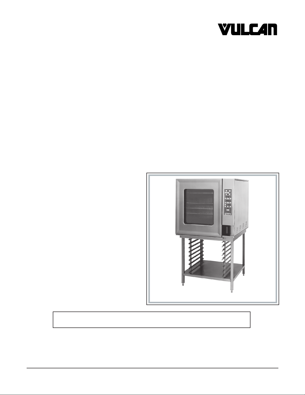
VCE6H ML-126177
VCE10H ML-126178
VCE10F ML-126179
VCE20H ML-126172
VCE20F ML-126173
For additional information on Vulcan-Hart or to locate an authorized parts
and service provider in your area, visit our website at www.vulcanhart.com
Model VCE10H
VULCAN-HART P.O. BOX 696, LOUISVILLE, KY 40201-0696
DIVISION OF ITW FOOD EQUIPMENT GROUP, LLC TEL. (502) 778-2791
WWW.VULCANHART.COM
FORM 31140 Rev. A (Sept. 2004)
Page 2

TABLE OF CONTENTS
GENERAL . . . . . . . . . . . . . . . . . . . . . . . . . . . . . . . . . . . . . . . . . . . . . . . . . . . . 3
INSTALLATION. . . . . . . . . . . . . . . . . . . . . . . . . . . . . . . . . . . . . . . . . . . . . . . . 3
UNPACKING . . . . . . . . . . . . . . . . . . . . . . . . . . . . . . . . . . . . . . . . . . . 3
LOCATION . . . . . . . . . . . . . . . . . . . . . . . . . . . . . . . . . . . . . . . . . . . . 3
STACKING KITS . . . . . . . . . . . . . . . . . . . . . . . . . . . . . . . . . . . . . . . . 3
LEGS OR CASTERS . . . . . . . . . . . . . . . . . . . . . . . . . . . . . . . . . . . . 4
LEVELING . . . . . . . . . . . . . . . . . . . . . . . . . . . . . . . . . . . . . . . . . . . . . 4
CONDENSATE DRIP PAN . . . . . . . . . . . . . . . . . . . . . . . . . . . . . . . . 4
PLUMBING CONNECTIONS . . . . . . . . . . . . . . . . . . . . . . . . . . . . . . 5
WATER REQUIREMENTS . . . . . . . . . . . . . . . . . . . . . . . . . . . . 5
WATER SUPPLY CONNECTIONS . . . . . . . . . . . . . . . . . . . . . 5
DRAIN CONNECTION . . . . . . . . . . . . . . . . . . . . . . . . . . . . . . . 5
ELECTRICAL CONNECTION . . . . . . . . . . . . . . . . . . . . . . . . . . . . . 6
VENT HOOD . . . . . . . . . . . . . . . . . . . . . . . . . . . . . . . . . . . . . . . . . . . 6
BEFORE FIRST USE . . . . . . . . . . . . . . . . . . . . . . . . . . . . . . . . . . . . 6
OPERATION . . . . . . . . . . . . . . . . . . . . . . . . . . . . . . . . . . . . . . . . . . . . . . . . . . 7
DOOR OPENING AND CLOSING . . . . . . . . . . . . . . . . . . . . . . . . . . 7
GREASE FILTER . . . . . . . . . . . . . . . . . . . . . . . . . . . . . . . . . . . . . . . 7
LOADING THE OVEN . . . . . . . . . . . . . . . . . . . . . . . . . . . . . . . . . . . 8
UNLOADING THE OVEN . . . . . . . . . . . . . . . . . . . . . . . . . . . . . . . . . 9
BUZZER . . . . . . . . . . . . . . . . . . . . . . . . . . . . . . . . . . . . . . . . . . . . . . 9
COOL DOWN . . . . . . . . . . . . . . . . . . . . . . . . . . . . . . . . . . . . . . . . . . 9
PROGRAMMABLE CONTROLS . . . . . . . . . . . . . . . . . . . . . . . . . . 10
PROBE . . . . . . . . . . . . . . . . . . . . . . . . . . . . . . . . . . . . . . . . . . 12
COOKING WITH THE PROBE . . . . . . . . . . . . . . . . . . . . . . . 12
USING THE TEMPERATURE PROBE . . . . . . . . . . . . . . . . . 12
TEMPERATURE PROBE APPLICATIONS . . . . . . . . . . . . . . 13
ENTERING A COOKING PROGRAM . . . . . . . . . . . . . . . . . . 13
PROGRAMMING MEMORY. . . . . . . . . . . . . . . . . . . . . . . . . . 14
RECALLING A PROGRAM FROM MEMORY . . . . . . . . . . . 15
BAKING (CONVECTION BAKING - HOT AIR) . . . . . . . . . . . 16
CONVECTION BAKING APPLICATIONS . . . . . . . . . . . . . . . 17
STEAMING . . . . . . . . . . . . . . . . . . . . . . . . . . . . . . . . . . . . . . . 18
STEAMING APPLICATIONS . . . . . . . . . . . . . . . . . . . . . . . . . 19
COMBI (CONVECTION BAKING WITH STEAMING) . . . . . 20
COMBI APPLICATIONS . . . . . . . . . . . . . . . . . . . . . . . . . . . . . 21
COOK AND HOLD . . . . . . . . . . . . . . . . . . . . . . . . . . . . . . . . . 22
COOK AND HOLD APPLICATIONS . . . . . . . . . . . . . . . . . . . 23
EXAMPLE PROGRAM . . . . . . . . . . . . . . . . . . . . . . . . . . . . . . 24
MENU CARD . . . . . . . . . . . . . . . . . . . . . . . . . . . . . . . . . . . . . . 25
DELUXE MANUAL CONTROL . . . . . . . . . . . . . . . . . . . . . . . . . . . . 28
ENTERING A MANUAL COOKING OPERATION . . . . . . . . 29
STANDARD MANUAL CONTROL . . . . . . . . . . . . . . . . . . . . . . . . . 30
ENTERING A MANUAL COOKING OPERATION . . . . . . . . 31
CLEANING . . . . . . . . . . . . . . . . . . . . . . . . . . . . . . . . . . . . . . . . . . . 32
DAILY CLEANING . . . . . . . . . . . . . . . . . . . . . . . . . . . . . . . . . 32
COMPLETE CLEANING. . . . . . . . . . . . . . . . . . . . . . . . . . . . . 32
MAINTENANCE . . . . . . . . . . . . . . . . . . . . . . . . . . . . . . . . . . . . . . . . . . . . . . 34
CLEAN CYCLE DELIMING PROCEDURE . . . . . . . . . . . . . . . . . . 34
CONFIGURATION MODE — PROGRAMMABLE CONTROL . . . 36
CONFIGURATION MODE — MANUAL CONTROL . . . . . . . . . . . 38
TROUBLESHOOTING . . . . . . . . . . . . . . . . . . . . . . . . . . . . . . . . . . . . . . . . . 40
SERVICE ADJUSTMENTS . . . . . . . . . . . . . . . . . . . . . . . . . . . . . . 40
SERVICE AND PARTS INFORMATION . . . . . . . . . . . . . . . . . . . . 40
–2–
Page 3

Installation, Operation, and Care of
ELECTRIC COMBI, CONVECTION & STEAM OVENS
SAVE THESE INSTRUCTIONS
GENERAL
The Electric Combi, Convection & Steam Ovens are single compartment ovens that provide convection
heating and/or steaming in the cooking chamber. Humidification can be provided by the internal steam
generator or by water injection (water vaporizes on contact with the hot oven interior).
The Vulcan Combi Electric ovens are sized 6, 10, or 20 levels high. The 6 level ovens are Half depth
only. The 10 and 20 level ovens are either Full or Half depth. All models include one of the three
controls: Manual Standard, Manual Deluxe, or Programmable. The bold numbers and letters explain
the model-number conventions.
The 6 or 10 high ovens can be installed on a suitable countertop using the legs (standard) or on an
accessory Stand. The accessory Stand may be equipped with an accessory Pan Slide which provides
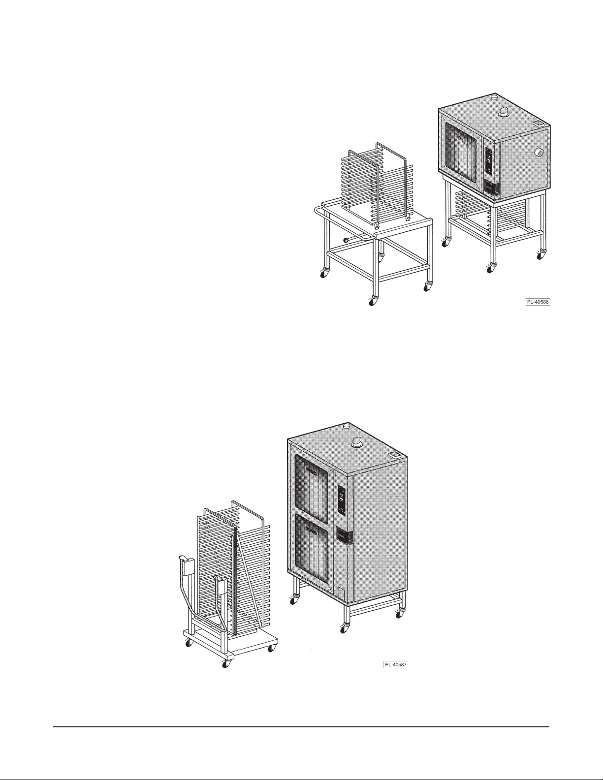
rack or pan storage underneath the oven. On 6 or 10 level ovens, the accessory Landing Table can
load or unload all Racks in one motion when the oven is mounted on the accessory stand or on a
countertop at the proper elevation. Additional Pan Racks and Racks are also available accessories.
The 20 level ovens can be installed with legs or with accessory casters. Accessory 20 Level Half and
20 Level Full Trolleys allow loading or unloading all racks in one motion (trolleys may be priced with
ovens). An available Hose Spray accessory can be installed near the oven to facilitate easy cleaning.
INSTALLATION
UNPACKING
Immediately after unpacking the oven, check for possible shipping damage. If the oven is found to be
damaged, save the packaging material and contact the carrier within 15 days of delivery.
Prior to installation, verify that the electrical service agrees with the specifications on the oven data
plate.
LOCATION
Allow space for operating the oven. Do not obstruct the ventilation ports above the oven. To provide
ventilation access, allow 4" clearance on the right side of the oven and 6" clearance at the rear. A
suitable amount of space should be provided for machine operation, cleaning, and service.
STACKING KITS
Stacking kits are available to allow ovens to stack, one on top of the other (available for 6 and 10 level
ovens only). The bottom oven must be larger or the same size as the upper oven. Assembly
Instructions are included with the kit.
–3–
Page 4
LEGS OR CASTERS
WARNING: THE OVEN MUST BE BLOCKED AND STABLE BEFORE INSTALLING LEGS OR
CASTERS.
Raise up and block the oven a minimum of 10" from the floor. Threaded holes are provided at the four
corners underneath the oven; screw the threaded stud of the four legs or optional casters into the
threaded holes. Four flanged legs allow anchoring to the floor (anchoring hardware not provided).
Casters with brake should be installed at front, casters without brake, at rear.
Available Installation Accessories
Model Legs* or Casters Stand with Legs* or Casters Stacking Kit with Legs* or Casters
VCE6H
VCE10H
VCE10F
VCE20H
VCE20F
* Leg height will vary with application.
Legs Stand with Legs Stacking Kit with Legs
Stand with Casters Stacking Kit with Casters
Legs Stand with Legs Stacking Kit with Legs
Stand with Casters Stacking Kit with Casters
Legs Stand with Legs Stacking Kit with Legs
Stand with Casters Stacking Kit with Casters
Legs
Casters
Legs
Casters
Use legs or casters on an oven if setting on floor. To provide common mating heights with trolleys, the
20 level half depth ovens use 7
1
/4" legs or casters while the 20 level full depth ovens use 85/8" legs or
casters. Use legs only on an oven setting on a counter. Use legs or casters on stand if oven will sit
on stand. Use legs or casters on bottom oven with stacking kit.
Casters may be used on an oven setting on the floor (not on an oven setting on a countertop). Casters
may be used on an accessory stand or on the bottom oven with an accessory stacking kit. Caster
equipped units should be installed with flexible plumbing and electrical connections to allow the unit(s)
to be pulled out for cleaning or servicing. When moving the oven, the operator should not exceed the
limitations of any flexible connections.
LEVELING
Caster equipped ovens must be placed on a level floor.
For ovens with legs, use a spirit level or pan of water in the bottom of the oven to make sure the oven
is level, both front-to-back and side-to-side. Adjust the leveling feet on the bottom of the legs by turning
the feet in or out to level the oven. After the drain is connected, check for level by pouring water onto
the floor of the compartment. All water should drain through the drain opening.
CONDENSATE DRIP PAN
Remove screws under front of oven base and assemble condensate
drip pan to bottom of oven (Fig. 2) using the thumb screws supplied
loose with the oven. Condensate drip pan is incorporated with front
cover of Stacking Kit accessory for the upper oven only. The lower
oven of a stacked pair uses the standard condensate drip pan. The
20 level oven has a three-segment condensate gutter.
–4–
Oven
Condensate Drip Pan
Door
Fig. 1
Page 5

PLUMBING CONNECTIONS
WARNING: PLUMBING CONNECTIONS MUST COMPLY WITH APPLICABLE SANITARY, SAFETY
AND PLUMBING CODES.
Water Requirements
Proper water quality can improve the taste of
the food prepared in the steamer, reduce
liming in the steam generator and extend
equipment life. Local water conditions vary
from one location to another. Ask your
municipal water supplier for details about
your local water supply prior to installation.
Supply Pressure 20 — 60 psig
Hardness* less than 3 grains
Silica less than 13 ppm
Total Chlorine less than 4.0 ppm
pH range 7 — 8
Undissolved Solids less than 5 microns
* 17.1 ppm = 1 grain of hardness
WATER REQUIREMENTS
Presence of sediment, silica, excess chlorides or other dissolved solids may lead to a recommendation
for alternate form(s) of water treatment. Test the water with the test strip included with the combi oven.
Other factors affecting steam generation are iron content, amount of chloridation and dissolved gases.
A local water treatment specialist should be consulted before installation of steam generating
equipment.
Water Supply Connections (Fig. 2)
A water filter system is recommended for the water supply line going to the treated water inlet of your
oven. Follow the recommendations for use and installation instructions shipped with the water filter.
If a water filter is not installed, the oven warranty may be limited.
Connect treated potable water (hot or cold) to the inlet labeled for treated water to supply the steam
generator tank and humidifier. Untreated water contains scale producing minerals which, if supplied
to the steam generator, can precipitate onto the surfaces in the steam generator tank. Due to the
temperatures in the tank, the minerals can bake onto the surfaces and components. This can result
in early component failure and reduced product life. Sensors in the steam generator tank use ions in
the water to detect the water level. Do not use distilled (fully demineralized or de-ionized) water as this
could provide a false reading to the sensors.
Connect untreated potable water (must be cold) to the inlet labeled for untreated water to supply the
condenser which cools the drain water.
Both external-threaded nylon inlets
3
/4" hose bibb (3/4" NSHT, National
Straight Hose Thread) are located at the rear of the oven. The nylon threads
Water Supply Inlets . . .
at Bottom Rear Corner of Oven
. . . Model VCE6H Shown.
should be treated carefully so the connections do not leak. A manual shutoff
valve should be provided, convenient to the oven, for each water supply line;
both of these valves should be open when the oven is in operation. Water
pressure for both incoming water lines should be between 20 and 80 psig.
Refer also to CLEAN CYCLE DELIMING PROCEDURE, pages 34 – 35.
Drain Connection
Fig. 2
CAUTION: In order to avoid any back pressure in the oven, do not connect solidly to any drain.
Extend the drain line from the 1
1
/2" NPT drain pipe extending from the bottom of the oven at the rear
to an open gap-type drain. Drain piping must have suitable pitch, have appropriate support along its
length, and have no connection to other piping. The material used in the drain line should be heat
resistant to at least 212°F.
– 5 –
Page 6

ELECTRICAL CONNECTION
WARNING: ELECTRICAL AND GROUNDING CONNECTIONS MUST COMPLY WITH APPLICABLE
PORTIONS OF THE NATIONAL ELECTRICAL CODE AND/OR OTHER LOCAL ELECTRICAL CODES.
WARNING: DISCONNECT THE ELECTRICAL POWER SUPPLY FROM THE OVEN AND
FOLLOW LOCKOUT / TAGOUT PROCEDURES.
The wiring diagram is located on the inside surface of the right side panel as you face the oven. Use
copper wire rated for at least 90°C for the connection.
ATADLACIRTCELE
EZISTIUCRICHCNARB
NOITCETORPDNANOITCETORPDNA
NOITCETORPDNANOITCETORPDNA
NOITCETORPDNA
ledoMhP/zH/stloV
SPMASPMA
SPMASPMA
SPMA
yticapmAtiucriCmuminiM
eciveDevitcetorPmumixaMeciveDevitcetorPmumixaM
eciveDevitcetorPmumixaMeciveDevitcetorPmumixaM
eciveDevitcetorPmumixaM
3/06/802
H6ECV
H01ECV
F01ECV
H02ECV
F02ECV
3/06/042
3/06/084
3/06/802
3/06/042
3/06/084
3/06/802
3/06/042
3/06/084
3/06/802
3/06/042
3/06/084
53
03
51
07
06
03
09
08
04
521
011
06
.noitidetsetal,07APFN/ISNA,edoClacirtcelElanoitaNehthtiwecnadroccanidelipmoC
NOTE: Only single-phase fan motors are used on these ovens so there is no need to check direction
of motor rotation. The fan will rotate in the proper direction.
VENT HOOD
Some local codes may require the Combi oven to be located under an exhaust hood. Information on
the construction and installation of ventilating hoods may be obtained from
Cooking Equipment
, NFPA standard No. 96 (latest edition).
Vapor Removal from
BEFORE FIRST USE
Before using the oven for the first time, it must be "burned in" to release any odors that might result from
heating the new surfaces in the oven. Operate the oven at 480°F for 45 minutes in Convection H
OT
AIR Mode. Depending on which control is furnished, perform CONFIGURATION MODE —
PROGRAMMABLE CONTROL on pages 36 – 37 or CONFIGURATION MODE — MANUAL CONTROL
on pages 38 – 39.
– 6 –
Page 7
OPERATION
WARNING: THE OVEN AND ITS PARTS ARE HOT. USE CARE WHEN OPERATING, CLEANING
OR SERVICING THE OVEN. THE COOKING COMPARTMENT CONTAINS LIVE STEAM. STAY
CLEAR WHEN OPENING DOOR.
DOOR OPENING AND CLOSING
The oven door is equipped with an electrically powered lock. The oven is delivered with the door
latched and slightly open (Fig. 3) and can be opened by firmly pulling the door handle (Fig. 5). Push
the door until it connects with the latch but remains slightly open (Fig. 3). This is the position the door
should be in when the oven is not in use. The door should also be in this position after cooking to allow
steam to escape before fully opening the door. Push the handle until it is in line with the oven door.
If power has been connected, the door will now lock automatically, sealing the oven chamber (Fig. 4).
To release the door, rotate (pull) the handle 90 degrees. The door automatically releases to the
'latched and slightly opened' position. Allow a few seconds for steam to escape before pulling the door
open (Fig. 5).
NOTE: On Programmable Controls if the ON button is pushed after the oven is turned on, the door will
be latched but slightly open (Fig. 3) for three seconds; the handle can be released by rotating 90
degrees as shown in Fig. 5. If the handle is not released within the three second interval, the door will
automatically re-close. A separate Door Open button will perform the same function with Manual
Standard or Deluxe Controls.
→
Fig. 3 Fig. 4 Fig. 5
NOTE: In the event of a power failure, the door may be opened by pulling the handle firmly towards
you while firmly pressing against the front of the oven with the other hand (avoid hot air contact).
GREASE FILTER
The grease filter in the rear of the oven chamber should be in place when roasting meat items but may
be removed before baking items that do not produce grease-laden vapors. See Cleaning, page 32,
for information on how to remove the grease filter.
– 7 –
Page 8
LOADING THE OVEN
Open the door. Place the product to be cooked in suitable containers and slide into the racks or place
the containers securely on shelves in the oven.
When loading a 6 or 10 level oven with the landing
table (Fig. 6), the bottom frame of the rack should
be secured by the rotary lock. Move the loaded
landing table to the front of the open oven; secure
the landing table to the oven by actuating the
locking-clamp (or use your body to hold the landing
table against the oven). Rotate the lock-knob to
release the pan rack and carefully roll the loaded
pan rack into the oven, making sure that the landing
table does not separate from the oven during the
transfer.
NOTE: When the landing table is not in use on the
6 or 10 level oven, make sure the rack retainer
(delivered with the oven) is fitted under the fan
baffle to prevent the pan rack from tilting when pans
are being removed.
Fig. 6
When loading a 20 level oven with the trolley (Fig. 7), make sure the handle is locked in the down
position so the rack is held securely to the trolley with its lifting hooks. Carefully move the loaded trolley
completely into the open oven. When the rear frame of the rack is positioned behind the edge of the
retainer, raise the handle to lower the rack-frame to the oven door.
Fig. 7
– 8 –
Page 9
UNLOADING THE OVEN
Allow the door to be 'slightly-opened' for a few seconds to allow hot air and steam to escape. Stand
behind the door while opening.
When unloading a 6 or 10 level oven, move the landing table so the clamp locks the landing table to
the front of the oven (or use your body to hold the landing table against the oven). Remove the landing
table handles and clamp them to the bottom of the hot oven pan rack. Carefully roll the hot pan rack
onto the landing table platform, making sure that the landing table does not separate from the oven
during transfer. Rotate the knob to allow the rack to move completely to the front of the landing table;
and rotate the knob back to lock the pan rack in place.
When unloading a 20 level oven, move the trolley (Fig. 7) into the oven until the "lift-hooks" are inserted
into both sides of the front frame of the rack in the correct "lift" position. Lower the trolley handle until
it stops; the loaded rack is lifted from its retainer and held securely to the trolley by the "lift-hooks". The
trolley may now be removed from the oven with the loaded rack securely held in place.
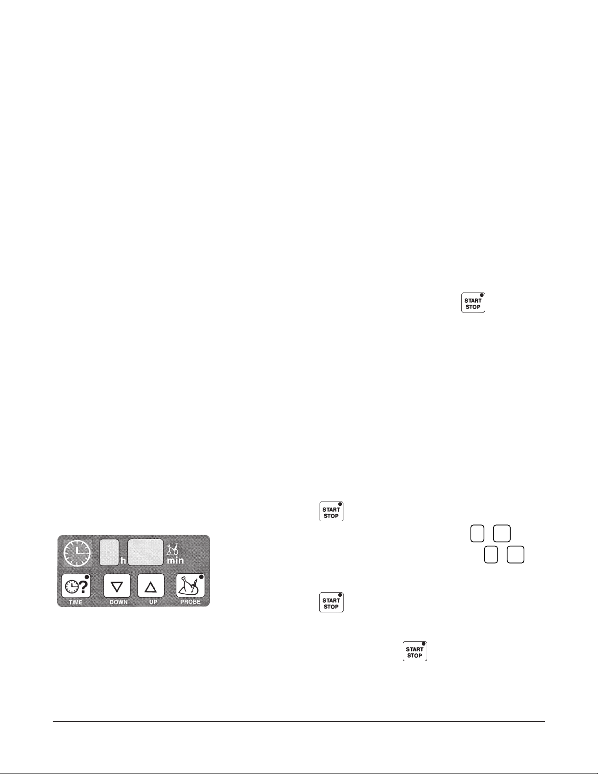
BUZZER
When either the Cooking Time has elapsed or the final internal Probe Temperature has been reached,
the buzzer will sound [ ON for 15 seconds and OFF for 45 seconds ] until Start / Stop,
, is pressed.
If done, the product should be removed, portioned, and served. The Buzzer can be adjusted two ways:
Buzzer loudness can be adjusted by your service technician. Buzzer frequency can be set in
configuration mode (page 36 or 38, depending on which control is furnished).
COOL DOWN
With either Programmable or Manual Controls, when the cooking phase is changed from a higher
temperature in Hot Air or Combi Modes to Steam Mode, the Humidifier discharges automatically. This
produces steam, opens the oven vent, and lowers the oven temperature to 212°F.
When empty after a cooking process has been completed, the oven may be too hot for the next
operation. The oven can use the Humidifier to cool itself. With Programmable Controls, Cool Down
can be programmed as one of the five Cooking Phases. To perform a Cool Down with Programmable
Controls, follow this procedure:
Press Start / Stop,
Press the down arrow key until the timer is clear,
Press the down arrow until the rain symbol displays,
, to stop operation.
– h – – min
h
' '
' ' ' '
.
min
The temperature is set at 158°F but can be further lowered to as low
as 86°F.
Press Start / Stop,
, to start operation.
The Humidifier will continue to discharge until 158°F or other set
temperature is reached.
Buzzer sounds. Press Start / Stop,
, to silence buzzer.
.
NOTE: With Programmable Controls, the Humidifier button can be used at any time to make steam and
lower the temperature.
– 9 –
Page 10
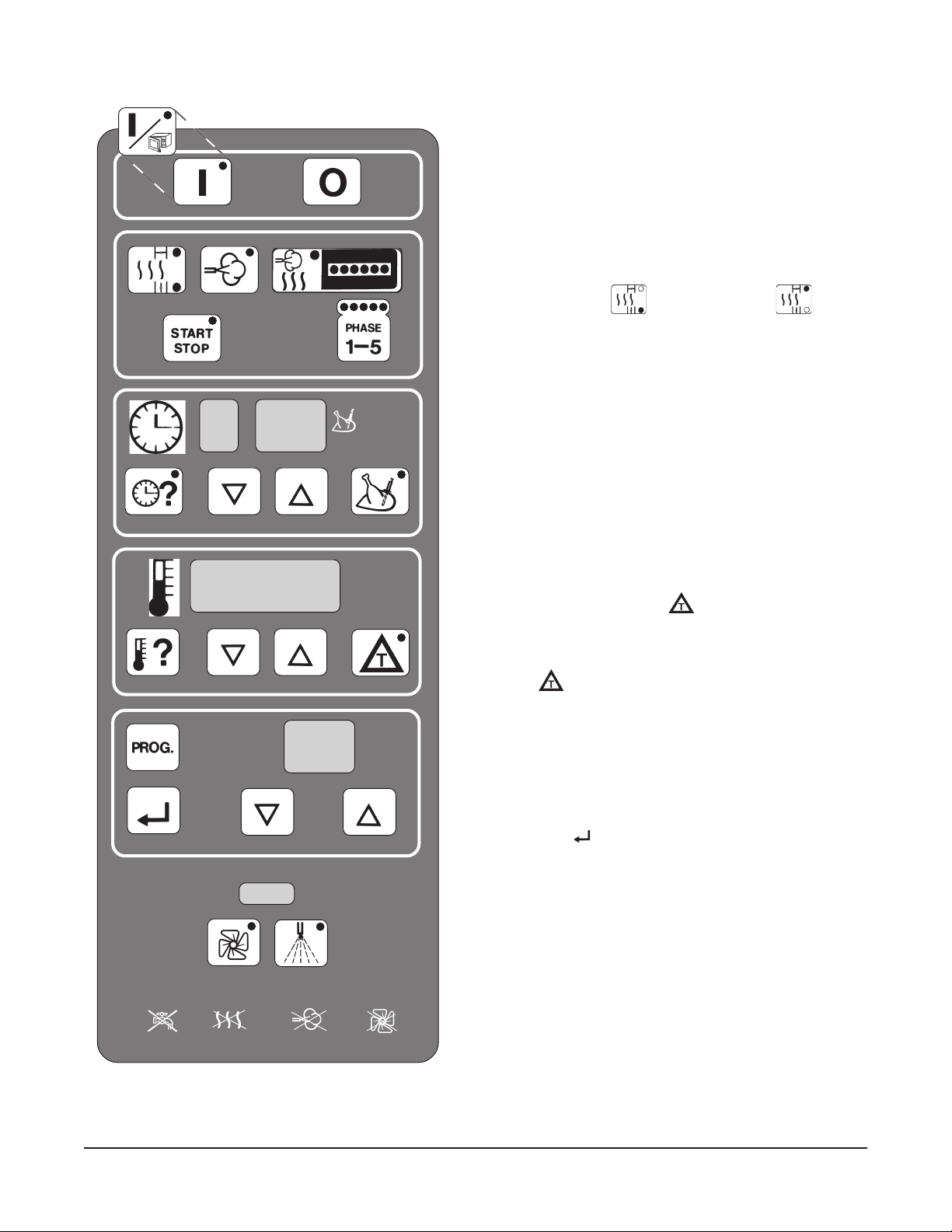
PROGRAMMABLE CONTROLS
ON
DOOR
ON
HOT AIR STEAM COMBI
h min
TIME DOWN UP PROBE
TEMP DOWN UP
OFF
ON OFF See Door Opening and Closing, page 7.
COOKING MODE
• HOT AIR (Convection Baking) also chooses
V
ENT CLOSED or VENT OPEN
• STEAM
• COMBI (Convection & Steam)
START ~ STOP PHASE 1 – 5
COOKING TIME or PROBE TEMPERATURE
• SET Cooking Time
• DISPLAY Cooking Time, remaining
• SET Probe Temperature, final
• DISPLAY Probe Temperature, actual
OVEN TEMPERATURE or
• SET Oven Temperature, desired
• DISPLAY Oven Temperature, actual
• SET
and use with Probe Temperature
ENTER DOWN UP
H C P C
1
/2
FAN SPEED HUMIDIFIER
PROGRAM NUMBER
• SET Cooking Programs
• RECALL or CHANGE a Cooking Program
• ENTER [
] to save the Cooking Program
FAN SPEED ~ Full or Half Power
HUMIDIFIER, non-programmable
(see Cool Down, p.9)
Trouble Indicator Lights:
Water Supply / Heat / Steam / Fan
– 10 –
Page 11
ON — After an initial power-up sequence, the control panel indicator lights and the light
inside the oven are lit. The actual oven temperature is shown in the Temperature
display, – h –– min is in the Time display, and –– is in the Program Number display.
The control will now accept commands. The ON button also cancels a manual
cooking operation of up to 5 Phases. • Open the water supply valve. See page 7.
OFF — Shuts off the oven and oven light, opens the oven vent, and drains the steam
generator tank (pump takes about a minute). • Close the water supply valve.
COOKING MODE
HOT AIR — Heat and Fan are ON; steam generator tank fills. Initial temperature setting is 302°F
(range is 35 – 518°F). Push once for Vent Closed,
; twice for Vent Open, .
STEAM — Steam and Fan are ON; steam generator tank fills, if not already full. Initial
temperature setting is 212°F (range is 35 – 212°F).
COMBI — Heat, Fan, and Steam are ON; steam generator tank fills, if not already full. Initial
temperature setting is 302°F (range is 35 – 518°F). The amount of steaming is set
by the number of times you press the Combi key (
1 – 6), indicated by the row of lights.
START STOP— Starts or stops a cooking operation. Temperature flashes if door is not locked.
PHASE 1–5 — Indicates the Phase of a cooking program. Allows you to step through and display
the cooking information for each phase of a cooking operation before starting.
COOKING TIME or PROBE TEMPERATURE
TIME — Displays the Cooking Time. Time remaining for
ALL phases is normally displayed.
Press the Time key again to display the time remaining for the current phase. When
- -- displays in the time display, the oven is in manual mode (no switch off at end).
DOWN — Decreases the Cooking Time or Probe Temperature setting.
UP — Increases the Cooking Time or Probe Temperature setting.
PROBE — Displays the Probe Temperature setting, initially 140°F, (range 70 – 210°F). After 5
seconds, displays the actual Probe Temperature.
OVEN TEMPERATURE or
TEMP — Displays the Oven Temp instead of . Normally displays the actual Oven Temp.
Press Temp to display the Oven Temperature setting for 5 seconds and adjust it.
DOWN — Decreases the Oven Temperature or setting.
UP — Increases the Oven Temperature or
setting.
— Displays instead of Oven Temperature (temperature difference is indicated by
__t in the display).
Temperature.
keeps the oven degrees warmer than the actual Probe
must be used with the Probe Temperature.
PROGRAM NUMBER
PROG. — Recalls and displays the cooking programs, by number, beginning with 00.
DOWN — Decreases the Program Number (range is 00 – 98).
UP — Increases the Program Number (range is 00 – 98).
ENTER — Stores the cooking parameters (up to 5 Phases) in memory under the Program
Number. Cooking parameters will not be lost during power outage or disconnection.
FAN SPEED — Push once for Half Speed (light is on); push twice for Full Speed (light is off).
HUMIDIFIER — Sprays a little water into the oven while button is pushed. Makes steam if oven is hot.
– 11 –
Page 12
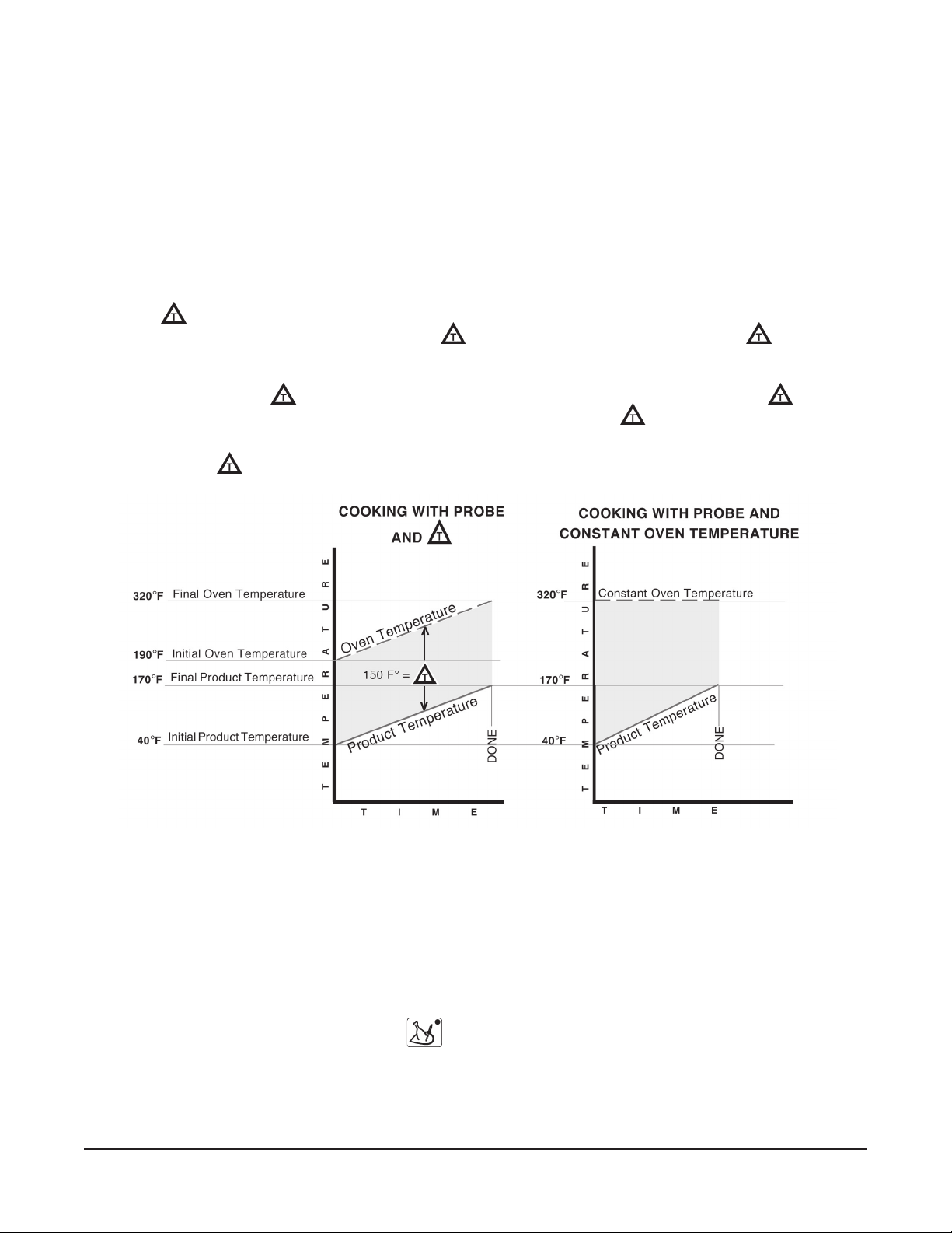
PROBE
The Probe Temperature defines the final temperature of the product for any cooking phase. The
cooking cycle stops when the product temperature reaches the probe temperature setting. Total
Cooking Time is not known or entered when using the probe.
COOKING WITH THE PROBE
There are two ways to control the oven temperature when using the Probe . . .
1) Setting the Oven Temperature at a constant value. The oven climbs to the set point and the product
cooks at that temperature. The cooking cycle ends when the product reaches the Probe
temperature setting. Or,
2) Using
increases, always maintaining the oven at
, the Oven temperature gradually increases as the internal temperature of the product
degrees warmer than the product. can provide
a slow cooking process that allows the product's required final internal temperature to be reached
without over-browning the outside of the product. The Probe Temperature (not cooking Time must
be used when using
maximum is 240 F°. For Steam Mode, the recommended minimum
. For Hot Air or Combi Modes, the recommended minimum is 110 F°;
is 60 F°; maximum is 180 F°.
The graph, below, shows two ways of controlling the oven temperature when using the Probe. The
150 F° value for
is used to show how the oven works and is not typical of any particular cooking
program.
USING THE TEMPERATURE PROBE
The Temperature Probe is kept in a metal holder at the top of the oven when not in use. Remove the
probe from its holder; the cable remains permanently connected to the top of the oven. Insert the
pointed end of the probe so its tip is approximately in the middle of the product to be cooked. The probe
cable is long enough to allow the product to be placed on one of the upper racks in the oven. The probe
can be used to define the final temperature for any phase of the cooking process and for any of the three
cooking modes: Convection (Hot Air), Steam, or Combi.
• To set the Probe Temperature, press
and use the UP and DOWN arrows to adjust the setting.
The Cooking Time cannot be used when the Probe Temperature is in use.
NOTE: During Operator training to demonstrate use of the probe, place the probe in a container of
water to simulate cooking of actual product.
– 12 –
Page 13

TEMPERATURE PROBE APPLICATIONS
All Applications are suggested only — prove your own recipes and temperature / time settings.
Product
Beef
Rare
Medium
Well Done
Lamb 175 – 185
Pork
Fresh
Smoked
Turkey
Whole
Boneless
Veal 170
ENTERING A COOKING PROGRAM
Recommended Final Probe Temperature
°F
140
160
170
170
140 – 170
185
170
1. When entering cooking parameters, always select
the Mode as the first element in a cooking phase:
OT A IR, STEAM, or COMBI (also, select Vent Closed
H
or Open for H
OMBI mode).
C
OT AIR mode and Steam Factor for
2. Enter the finish parameter for the cooking phase
OOKING TIME or PROBE TEMP.) with its value.
(C
3. Enter the oven control parameter for the cooking
phase (TEMP or
can be set at F
) with its value. FAN Speed
ULL or
1
/2.
4. Steps 1, 2, and 3 complete the parameters for that
phase. For any additional phase (or phases), press
the PHASE 1 – 5 key. Repeat steps 1, 2, 3, and 4
for each cooking phase.
5. If programming a repeat cooking process, select a
Program Number following the instructions for
Programming Memory on the next two pages.
6. Press
to start cooking; the indicator light in the
Start Stop key indicates the oven is operational.
7. When finished, press
again, to silence the
buzzer.
– 13 –
Page 14

PROGRAMMING MEMORY
Up to 99 Cooking Programs with up to 5 Phases in each program can be keyed-in and stored in
Memory. Each program is accessed by its identifying number. Program numbers range from 00 – 98.
A pre-defined Clean Cycle Deliming program is also available, see page 34.
If the numbered Program has not been programmed (or is vacant), the Time displays – h – – min. No
Mode or Phase indicator lights are lit. The Temperature displays – – or the current temperature.
REATE a new program —
To C
With — — in the program number display, the control is in Manual mode.
0 0
Press the key. Program Number 00 is displayed and the control is
— —
in Program Mode. Use UP or DOWN arrows to increase or decrease the
program number until a vacant program number is found.
ENTER THE COOKING INSTRUCTIONS (FOLLOW STEPS 1 – 6):
1) Select the cooking mode: Hot Air, Steam, or Combi.
If Hot Air, select Vent (Closed or Open).
If Combi, set Steam Factor.
2) Set either the Time or Probe Temperature.
3) Set the Oven Temperature or
. Select Fan 1/2 speed or full.
4) End of the 1st Phase. Press
5) Repeat steps 1 – 4 for as many of the 5 phases as are needed. Review
the program by stepping through the phases. Make any needed changes.
6) When the program is set, save it in memory by pressing
beep is heard.
NOTE: A cooking program can also be entered in manual mode and saved to a
program number by selecting the Program Number and pressing
three seconds.
ELETE an existing program —
To D
With — — in the program number display, the control is in Manual mode.
0 0
Press the
— —
in Program Mode. Use UP or DOWN arrows to increase or decrease the
program number until the program number to be deleted is displayed.
Press
indicating the program has been deleted.
to shift to the next phase.
until the
for about
key. Program Number 0 0 is displayed and the control is
and hold it in for about three seconds until the beep sounds,
NOTE: If a previous program had been selected and was active in manual mode,
it will be copied to the selected program number, replacing the previous program.
Verify that the program number is vacant after you delete it.
– 14 –
Page 15

To COPY an existing program to a
Recall and display the program number that you wish to copy.
NEW
program number —
HANGE a program —
To C
0 0
— —
Press
Change the program number to the
Press
to begin the program. Pause. Press to stop the program.
NEW
number.
until the beep sounds, indicating the program has been
copied.
With — — in the program number display, the control is in Manual mode.
Press the
key. Program number 00 is displayed. Use the UP or
DOWN arrows to increase or decrease until the program number you
want to change is displayed.
Step through each phase, making any temperature, time or other changes
for the phase; press
to shift to the next phase. The program number
begins to blink when one or more changes have been made to the
program.
AVE the changed cooking program, press and hold it in for about
To S
three seconds until the beep sounds.
RECALLING A PROGRAM FROM MEMORY
Once a menu item has been programmed, it can be recalled, reviewed and used to cook food.
If the Program has already been programmed, its values are recalled from memory and displayed. You
can view all the programmed information by stepping through the phases using the phase button.
ECALL a program from memory —
To R
With — — in the program number display, the control is in Manual mode.
0 0
Press the
key. Program Number 00 is displayed. Use the UP or
DOWN arrows to select the program number you want.
— —
Use the Phase 1 – 5 key to step-through and verify the cooking parameters
for each phase of the cooking program.
Load the oven. If using the probe, place it in the center of the product.
Close the door and press
to begin the cooking program. The
blinking indicator light in the Phase 1 – 5 key shows which phase of the
cooking program is being performed. If the program is timed, the display
shows the total time remaining. When the cooking program is done, the
buzzer will sound.
Press
to silence the buzzer. Check the product for doneness.
– 15 –
Page 16

BAKING (Convection Baking – HOT AIR)
Convection Baking involves baking, browning, roasting, etc. without adding steam or moisture to the
process. Hot air is fan-circulated to maintain even temperatures throughout the oven. Preheating the
oven before loading the product is recommended.
Automatic Convection Baking can be set up so the buzzer sounds when the Cooking Time has elapsed
or when the product's internal temperature has reached the Probe Temperature set point. If using the
Probe Temperature, insert the probe near the center of the product. Cooking Time is not used when
the Probe Temperature is in use.
If using the Probe Temperature, either the Oven Temperature or
during baking. If using the Oven Temperature setting, the oven temperature will remain constant
throughout the convection baking operation or phase. If using the Probe Temperature,
to keep the oven temperature
temperature gradually increases at the same rate as the internal temperature of the product, always
maintaining a constant difference. The result with
crusting on the outside of the product.
Turn the oven ON.
Select Convection (
1 05
For
350•F
For
degrees warmer than the Probe. With cooking, the oven
is slow baking or roasting with less brown
HOT AIR) Mode; and set the Vent Closed or Open.
standard automatic
• To set the Cooking Time, press
arrows to adjust the setting.
• To set the Oven Temperature, press
arrows.
final product temperature
baking, set the Cooking Time and Oven Temp.
baking, set the Probe Temperature.
can be used to control the oven
can be set
and use the UP and DOWN
and use the UP and DOWN
175
• To set the Probe Temperature, press
arrows. When the Probe Temperature indicator is lit, the numeric
value in the time display is the Probe Temperature in °F. Probe
Temperature can be used with either
slow baking or roasting
For
• To set
When the control is set, load the oven. If using the probe, place it in the
center of the product. Close the door and press
Upon completion of the baking process, when either the Cooking Time
has counted down or the Probe Temperature has been reached, the
buzzer will sound.
Press
, press and use the UP and DOWN arrows.
to silence the buzzer. Check the product for doneness.
– 16 –
, use with the final Probe Temperature.
and use the UP and DOWN
or .
to begin.
Page 17

CONVECTION BAKING APPLICATIONS – HOT AIR MODE
All Applications are suggested only — prove your own recipes and temperature / time settings.
tcudorPnoitaraperP
HSIF
hserf,telluMrodoCliO,nosaeS09305321-01
tellifhsifnezorf-aeSedisreppudnamottobetalplioylhguorohT
2rofdnatstel,gnikabretfA.tellifhsiffo
ekamdnagnikcitsdiovaotsetunim
.reisaegninoitrop
hserf,eloSliO,nosaeS52405321-01
hserf,tuorTliO,nosaeS52405321-01
nezorf,tuorTliO,nosaeS52405322-51
hserf,dedaerb,tuorTerutximbmurcdaerb,gge,ruolfnipiD
ylhguorohtnapesaerG
KROP
,hserf,pohCkroP
deetuas
,nezorf,pohCkroP
deetuas
hserf,teltuCkroP
zo5-4
,hserf,teltuCkroP
dedaerb
hserf,teltuCnioLkroP
zo5-4
hserf,kaetSmaHylthgilliO,nosaeS08405301-6
ylthgilliO,nosaeS08405321-01
gnitsaorretfanosaeS;ylthgilliO08452451
ylhguoroht,rettabbmurcdaerb,ggenipiD
diova,steltucehtfoecafrusdedaerbehtlio
.mottobetalplioylthgil,stopsyrdgnivael
sedishtobliO52405321-01
nosaestonoD0845248-6
(((((
pmeTtaeherP
O
)F
08405321-01
08453402-51
08452421-01
(((((O)F
pmeTnevO
emiT
)setunim()setunim(
)setunim()setunim(
)setunim(
hserf,egasuaSkroPylthgilliO08452401-8
hserf,kaetSkroPylthgilliO,nosaeS0050847
nezorf,kaetSkroPssecorpgnitsaorretfanosaeS,liO00552421-01
tcudorP
YRTSAP
yrtsaPffuP04304302-81
yrtsaPhsinaD05305302-81
yrtsaPykalF053-043053-04381-61
ekaC0530538
ekaCtiurF02302356-55
klimhtiwslloRtsaeY09309321-01
yrtsaPdnomlA05305321-01
yrtsaPtuN05305321-01
yrtsaPetalocohC05305321-01
yrtsaPtiucsiB05305321-01
pmeTtaeherP
O
(((((
)F
(((((O)F
pmeTnevO
emiT
)setunim()setunim(
)setunim()setunim(
)setunim(
– 17 –
Recommended setting for
in Convection Baking Mode is a
minimum of 110 F° (61 C°).
Page 18

STEAMING (Steam Mode only)
Steam cooking is used for stewing, poaching, and gentle cooking of products cooked in water. Steam
flows without pressure into the oven. The fan circulates the steam to all parts of the oven. Allow the
steam generator to preheat for 4 - 5 minutes if starting from cold. Also, it is recommended that you
preheat the oven using the Convection Baking (H
Automatic Steaming can be set up so the buzzer sounds when the Cooking Time has elapsed or when
the product's internal temperature has reached the Probe Temperature set point. If using the Probe
Temperature, insert the probe near the center of the product. Cooking Time is not used when the Probe
Temperature is in use.
Usually, the Cooking Time and Oven Temperature are used to control the steaming process.
Alternatively, the Probe Temperature can be used to indicate when cooking is done. When using the
Probe Temperature, either the Oven Temperature or
Turn the oven ON.
Select Steam Mode.
OT AIR) Mode.
can be used to control the oven.
212•F
10
170
standard automatic
For
Temperature.
• To set the Cooking Time, press
arrows.
• To set the Oven Temperature, press
arrows to adjust the setting.
For
final product temperature
• To set the Probe Temperature, press
arrows. When the Probe Temperature indicator is lit, the numeric
value in the time display is the Probe Temperature in °F. Probe
Temperature can be used with either
When the control is set, load the oven. If using the probe, place it in the
center of the product.
Close the door and press
Upon completion of the steaming process, when either the Cooking Time
has counted down or the Probe Temperature has been reached, the
buzzer will sound.
steaming, set the Cooking Time and the Oven
and use the UP and DOWN
and use the UP and DOWN
steaming, set the Probe Temperature.
and use the UP and DOWN
or .
to begin.
Press
to silence the buzzer. Check the product for doneness.
– 18 –
Page 19

STEAMING APPLICATIONS
All Applications are suggested only — prove your own recipes and temperature / time settings.
tcudorPnoitaraperP
SELBATEGEV
hserf,sugarapsA gnikoocerofebspordnomelhtiwelknirpS51-21
hserf,iloccorBgnikoocretfanosaeS81-51
nezorfrohserf,stuorpSslessurBgnikoocretfanosaeS81-51
hserf,decils,etihw,egabbaC 81-51
nezorfrohserf,llams,storraCgnikoocretfanosaeS02-81
hserf,decid,storraC 81-51
nezorfrohserf,rewolfiluaCgnikoocretfanosaeS81-51
hserf,daeh,rewolfiluaC gnikoocerofebspordnomelhtiwelknirpS02-81
decidrosecils,yreleC gnikoocerofebspordnomelhtiwelknirpS02-81
hserf,boc-eht-no,nroC gnikoocerofebspordnomelhtiwelknirpS81-51
tnalpggE 01
nezorfrohserf,snaeBneerGgnikoocretfanosaeS02-81
ro,deretrauq,devlah,smoorhsuM
decils
nezorf,saePgnikoocretfanosaeS51-21
seotatoP tlas,ro;gnikoocerofebsetunim51rofretawtlas%01nikaoS
yrd
hserf,hcanipS 4-2
gnikoocerofebspordnomelhtiwelknirpS01-8
emiT
)setunim()setunim(
)setunim()setunim(
)setunim(
53-03
SEHSIDEDIS
sllaBtaeM,sgnilpmuDretawdeddatuohtiwmaetS02-51
atsaP xiM.lioemosddadnaretawtohhtiwrevoc,gnikoocerofeB
eciR.htpedecirfo%051otretawddA52-02
TAEM
teksirB taemehtotselbategevdnagninosaesddA 021-09
eessacirf,laeV taemehtotselbategevdnagninosaesddA05-54
SNAECATSURC&HSIF
nezorfrohserf,tubilaH,doCnap/21,snoitropezisgnivresnI 21-01
nezorf,sliaThsifyarC llidhserfhtiwrevocspahrepdnaspordnomelhtiwelknirpS51-21
slessuMeniwemosddA01-8
hserf,nomlaSnomelhtiwnosaeS01-8
.ssecorpgnikoocehtgnirudecnoylhguoroht
Recommended setting for in Steam Mode is a minimum of 60 F° (33 C°).
52-02
– 19 –
Page 20

COMBI (Convection Baking with Steaming)
Combi baking / steaming is used for baking, roasting, or braising when steam needs to be added to the
oven during a convection baking operation. The 'Steam Factor' can be varied by repeat pressing of
the Combi key — see Steam Factor in the table below. It is recommended that you preheat the oven.
Automatic Combi baking / steaming can be set up so the buzzer sounds when the Cooking Time has
elapsed or when the product's internal temperature has reached the Probe Temperature set point. If
using the Probe Temperature, insert the probe near the center of the product. Cooking Time is not used
when the Probe Temperature is in use.
Usually, the Cooking Time and Oven Temperature are used to control the Combi baking / steaming
process. Alternatively, the Probe Temperature can be used to indicate when cooking is done. When
using the Probe Temperature, either the Oven Temperature or can be used to control the oven.
Turn the oven ON.
135
325•F
170
Select Combi Mode and set the Steam Factor (see table below).
For
standard automatic
Temperature and the Cooking Time.
• To set the Cooking Time, press
arrows.
• To set the Oven Temperature, press
arrows to adjust the setting.
final probe temperature
For
Temperature.
• To set the Probe Temperature, press
arrows. When the Probe Temperature indicator is lit, the numeric
value in the time display is the Probe Temperature in °F. Probe
Temperature can be used with either
When the control is set, load the oven. If using the probe, place it in the
center of the product. Close the door and press
Upon completion of the Combi baking with steaming process, when either
the Cooking Time has counted down or the Probe Temperature has been
reached, the buzzer will sound.
Combi baking with steaming, set the Oven
and use the UP and DOWN
and use the UP and DOWN
Combi baking with steaming, set the Probe
and use the UP and DOWN
or .
to begin.
*
Press
to silence the buzzer. Check the product for doneness.
* When selecting Steam Factor, press 1 to 6 times to obtain the desired steaming.
Indicator Lights Combi Key Steam Factor
❍●●●●● Press one time. 5
❍❍●●●●
❍❍❍●●● Press three times. 20
❍❍❍❍●● Press four times. 30
❍❍❍❍❍● Press five times. 40
❍❍❍❍❍❍ Press six times. 50
Press two times. 10
– 20 –
Page 21

COMBI APPLICATIONS
All Applications are suggested only — prove your own recipes and temperature / time settings. Combi
applications typically begin with a Steam Mode phase which automatically preheats the steam
generator in readiness for a subsequent Combi Mode phase. Some applications contain a H
OT AIR
or Convection Mode phase. Combi Mode is seldom performed as a single phase cooking operation.
tcudorPnoitaraperP1esahP2esahP3esahP
FEEB
delloR&denoB
feeBtsaoR
eniwder
feeBtsaoRylthgilliodnanosaeSmaetS
sedaluoRddadna,lio,nosaeS
eniwder
feeBdesiarBmaetS
.bl3faoLtaeMnapniylthgilliOmaetS
egabbaCdeffutShtiwelknirps,nosaeS
snoino
deffuts,teksirB,laeVylthgillio,nosaeSmaetS
fonioLtsaoR,laeVdda,ylthgillio,nosaeS
ecuas
dna,snoino,skael
nworbdnayawarac
fosisabsaselbategev
KROP
sselenoB,nioLkroPeniwderddAmaetS
faoltaeMroeiPkroPrepbl5-4yletamixorppA
,egasuaSkroP
esraoc
enif,egasuaSkroPmaetS
sreppePdeffutSnogninepoehthtiwecalP
napmunimula
mottobeht
YRTLUOP
elohw.bl3,nekcihCliO,nosaeSibmoC
elohw
.bl11-9,yekruT
liO,nosaeSibmoC
emiTlatoT
)setunim()setunim(
)setunim()setunim(
)setunim(
,storracdda,lio,nosaeS
maetS
setunim09
setunim02
maetS
setunim03
setunim09
setunim01
maetS
setunim54
setunim02-51
maetS
setunim02
setunim01
maetS
setunim01
maetS
setunim6-5
setunim5
maetS
setunim54-04
03rotcaFmtS
setunim51
F°523
04rotcaFmtS
setunim08
F°572
ibmoC
setunim06
F°082-052
ibmoC
dnuoprepsetunim51
F°023-082
ibmoC
setunim04
F°023-082
ibmoC
setunim55
F°023
ibmoC
05rotcaFmtS
setunim02
F°052
ibmoC
setunim02
F°053
ibmoC
setunim07-06
F°092
ibmoC
setunim08-07
F°023-082
ibmoC
setunim04-03
F°023-082
ibmoC
setunim07-06
F°082-052
ibmoC
setunim6-5
F°053
ibmoC
setunim7-5
F°093
ibmoC
setunim51
F°043
noitcevnoC
setunim81
F°004
noitcevnoC
setunim03
F°523
– 051
noitcevnoC
setunim01
F°093-063
– 07
noitcevnoC
setunim01
F°093
noitcevnoC
setunim01
F°052
– 56
– 09-57
– 001-09
– 05-04
– 08-07
– 21-01
– 21-01
– 06-55
lanretnIlaniF
erutarepmeT
rennIF°571
hgihT
lanretnIlaniF
erutarepmeT
rennIF°571
hgihT
—
551
lanretnIlaniF
erutarepmeT
F°561
33
011
– 21 –
Page 22

COOK AND HOLD
Cook and Hold is set up as a two-phase cooking process. The first phase is programmed similar to
any other Convection, Steam, or Combi operation by selecting: 1) the mode 2) the finish cooking
parameter (cooking time or probe temperature, with its value) and 3) the oven control parameter (oven
temperature or
, with its value).
During the second phase of the cooking process, the Oven Temperature is typically set at 140°F. Oven
heat is allowed to dissipate slowly while the internal temperature of the product is still increasing.
Select ––– for the Cooking Time to be on H
OLD for the second phase. Select
1
/2 Fan Speed for
the second phase of the cooking operation.
Turn the oven ON.
The phase indicator for the first phase is blinking.
Select the cooking mode for phase one: Hot Air, Steam, or Combi.
• In Hot Air mode, select Vent Closed or Vent Open.
• In Combi mode, set the Steam Factor.
Select the finish parameter for the first phase,
or and
enter its value using the UP and DOWN arrows.
Select the oven control parameter for the first phase, or
and its value.
Press the Phase key. The phase two indicator light should be
blinking.
Select the cooking mode for phase two: Hot Air, Steam, or Combi.
• In Hot Air mode, select Vent Closed or Vent Open.
• In Combi mode, set the Steam Factor.
———
Press
and use the DOWN arrow (one step below 0) . . .
until – – – displays in the time display for the second phase.
Press
and DOWN arrows. Press
and set the Hold Temperature at 140°F using the UP
to set the fan at half speed during
the second phase HOLD mode.
Load the oven. Insert the probe (optional). Close the door.
Press
to begin.
After completing the first phase, the oven temperature will decline
to the 140°F HOLD temperature and will maintain that temperature
with the fan at
1
/2 speed until the oven is shut off manually.
– 22 –
Page 23

COOK AND HOLD APPLICATIONS
All Applications are suggested only — prove your own recipes and temperature / time settings.
This two-stage process cooks roast beef or other products slowly and efficiently. During the first phase,
the oven cooks at the Oven Temperature for a set amount of time or until a Probe Temperature is
reached. When the first phase is complete, the oven heaters turn off and fan is at half speed. The
roast continues to cook as the temperature declines to the Hold Temperature, (140°F for beef). The
heaters then resume at half power, maintaining the "ready-to-serve" or Hold Temperature indefinitely.
After unloading, the oven can be used for its next cooking task or shut off manually.
Cook And Hold — Rolled Beef Roasts – Refrigerated, Not Frozen
Oven Temp °F 200 °F 250 °F 300 °F
Doneness
Final Internal Temp °F
Rare
140 °F
Med
160 °F
Rare
140 °F
Med
160 °F
Rare
140 °F
Weight (pounds) Phase 1 Cooking Time (minutes)
8 165 225 105 135 90 105
9 180 240 120 150 90 120
10 195 270 135 165 105 120
11 210 285 135 180 105 135
12 225 315 150 195 105 150
13 240 330 165 210 120 150
14 255 360 165 225 120 165
15 270 375 180 225 135 165
16 285 390 180 240 135 180
17 300 405 195 255 150 180
18 300 420 210 270 150 195
19 315 450 210 270 165 210
20 330 465 225 285 165 210
21 345 480 225 300 180 225
22 360 495 240 300 180 225
23 375 510 240 315 180 240
24 375 540 255 330 195 240
25 390 555 270 345 195 255
26 405 570 270 345 210 270
27 420 585 270 360 210 270
28 435 600 285 375 210 270
29 450 615 300 390 225 285
30 450 630 300 390 225 285
Allow additional time (minutes) for the oven temp-
erature to decline to the Hold Temperature (140 °F)
60 minutes 90 minutes 120 minutes
Med
160 °F
Cook And Hold — Standing Rib Roast – Refrigerated, Not Frozen
Oven Temp °F 200 °F 250 °F 300 °F
Doneness
Final Internal Temp °F
Rare
140 °F
Med
160 °F
Rare
140 °F
Med
160 °F
Weight (pounds) Phase 1 Cooking Time (minutes)
8 135 195 90 120 75 90
9 150 210 90 120 75 90
10 150 210 105 135 75 90
11 165 225 105 135 90 105
12 165 240 105 150 90 105
13 180 240 120 150 90 105
14 180 255 120 150 90 105
15 180 255 120 165 90 120
16 195 270 120 165 105 120
17 195 285 135 165 105 120
18 210 285 135 180 105 120
19 210 300 135 180 105 135
20 210 300 150 180 105 135
21 225 300 150 195 105 135
22 225 315 150 195 120 150
23 240 330 150 195 120 150
24 240 330 165 210 120 150
25 240 330 165 210 120 150
26 240 345 165 210 120 150
27 255 345 165 210 120 165
28 255 360 180 225 120 165
29 270 360 180 225 135 165
30 270 360 180 225 135 165
Allow additional time (minutes) for the oven temp-
erature to decline to the Hold Temperature (140 °F)
60 minutes 90 minutes 120 minutes
Rare
140 °F
Med
160 °F
Cook And Hold — Other Foods
Oven
Quantity Size
Leg of Lamb 1 or more of same size 5 - 15 lb each 300 20 min / lb 5 min / lb 180
Smoked Ham, fully cooked 1 or more of same size 15 lb each 300 120 min 150 min 155
Chicken
Duckling
Turkey 1 or more of same size
White Potatoes, baked,
in jackets
1 - 12 of same size 2 - 3 lb each
18 - 24 of same size 2 - 3 lb each 40 min 15 min
1 - 5 of same size 3.5 - 4 lb each
6 - 10 of same size 3.5 - 4 lb each 70 min 25 min
12 lb each
14 lb each 150 min
16 lb each 175 min
18 lb each 200 min
20 lb each 220 min
22 lb each 240 min
up to 50 pounds
120 count 400
80 - 100 pounds 50 min
up to 50 pounds
80 count 400
80 - 100 pounds 60 min
Temp
°F
300
325
250
Time ( minutes)
Phase 1
Cook
30 min 10 min
55 min 15 min
125 min
30 min
40 min
Hold
Additional
55 min 190
15 min 20060 - 75 pounds 40 min
15 min 20060 - 75 pounds 50 min
Final
Internal
Temp °F
180
200
– 23 –
Page 24

EXAMPLE PROGRAM
This example shows how to program a three-phase process for cooking Roast Beef, 18 pounds per
roast, and store it as program number 20.
The second item in the table on page 21 provides most of the information: For Combi time, Phase 2,
15 minutes-per-pound times 18 pounds-per-roast equals 270 minutes (or 4 hours and 30 minutes). We
assumed that Steam Factor at 20 would be OK. We chose the average temperature when a
temperature range was given. We chose to leave the Vent Closed during phase 3. In this example,
we will not use the temperature probe. Refer to the menu card example at the bottom of page 25.
Phase 1 Phase 2 Phase 3
STEAM Mode
212 °F
20 minutes
COMBI Mode - Steam Factor = 20
295 °F
4 hours and 30 minutes
HOT AIR Mode - Vent Closed
Turn the oven ON.
Phase 1 Select Steam Mode by pressing
. The first light blinks on the phase button
to indicate you are programming Phase 1. Press : The Temperature displays
212°F and needs no adjustment. Press
decrease until the Time displays [ –
h 20 min ]. Press to shift to Phase 2: The
and press to increase or to
second indicator light begins to flash.
Phase 2 Select Combi Mode - Steam Factor of 20 by pressing
three indicator lights will be lit indicating Steam Factor equals 20. Press
press
Press
h 30 min ]. Press to shift to Phase 3: The third indicator light begins to flash.
[ 4
to increase or to decrease until the Temperature displays 295°F.
and press to increase or to decrease until the Time displays
375 °F
10 minutes
3 times. The first
and
Phase 3 Select Convection
and press to increase or to decrease until the Temperature displays
375°F. Press
displays [ –
Press
Save Press the
h 10 min ].
twice.
key and press to increase or to decrease until the
Program Number displays
choose a different program number that is vacant. A vacant program displays the
current temperature, blank Time [ –
are lit. Then press
(HOT AIR) Mode by pressing once (Vent is Closed). Press
and press to increase or to decrease until the Time
. Verify that this program number is vacant, or
h – – min ], and no Mode or Phase indicator lights
until the beep is heard and the program is saved in memory.
– 24 –
Page 25

MENU CARD
PROGRAM NUMBER _______
Menu Item________________
MODE
Hot Air - Vent (Closed / Open)
Steam Co
mbi - ( Steam Factor
1
•, 2•, 3•, 4•, 5•, 6• )
Phase 1
Phase 2
Phase 3
Phase 4
Phase 5
Prep.
FINISH OVEN CONTROL
TIME
Hr. Min.
PROBE°FTEMP.
°F
F°
FAN
Speed
Full or
HUMIDIFIER
Manual
1
/
2
PROGRAM NUMBER 20
Menu Item ROAST BEEF
Hot Air - Vent (Closed / Open)
Steam Co
mbi - ( Steam Factor
1•, 2•, 3•, 4•, 5•, 6• )
Phase 1
Phase 2
Phase 3
3• ~ Steam Factor = 20
HOT AIR -
Vent Closed
Phase 4
Phase 5
MODE
STEAM
COMBI -
Prep.
18 pounds each - refrigerated at 40°F -
set at room temperature 1 hour before roasting
FINISH OVEN CONTROL
TIME
Hr. Min.
20 Min. 212°F Full No
4Hr. 30Min. 295°F Full No
10 Min. 375°F Full No
PROBE°FTEMP.
°F
F°
FAN
Speed
Full or
HUMIDIFIER
1
/
2
Manual
– 25 –
Page 26

PROGRAM NUMBER _______
Menu Item________________
MODE
Hot Air - Vent (Closed / Open)
Steam Co
mbi - ( Steam Factor
Phase 1
Phase 2
Phase 3
Phase 4
Phase 5
PROGRAM NUMBER _______
FINISH OVEN CONTROL
TIME
Hr. Min.
PROBE°FTEMP.
°F
F°
Prep.
FAN
Speed
Full or
HUMIDIFIER
Manual
1
/
2
Menu Item________________
MODE
Hot Air - Vent (Closed / Open)
Steam Co
mbi - ( Steam Factor
1
•, 2•, 3•, 4•, 5•, 6• )
Phase 1
Phase 2
Phase 3
Phase 4
Phase 5
FINISH OVEN CONTROL
TIME
Hr. Min.
PROBE°FTEMP.
°F
F°
Speed
Full or
FAN
HUMIDIFIER
Manual
1
/
2
– 26 –
Page 27

PROGRAM NUMBER _______
Menu Item________________
Prep.
MODE
Hot Air - Vent (Closed / Open)
Steam Co
mbi - ( Steam Factor
1•, 2•, 3•, 4•, 5•, 6• )
Phase 1
Phase 2
Phase 3
Phase 4
Phase 5
PROGRAM NUMBER _______
FINISH OVEN CONTROL
TIME
Hr. Min.
PROBE°FTEMP.
°F
F°
Prep.
FAN
Speed
Full or
HUMIDIFIER
Manual
1
/
2
Menu Item________________
MODE
Hot Air - Vent (Closed / Open)
Steam Co
mbi - ( Steam Factor
1
•, 2•, 3•, 4•, 5•, 6• )
Phase 1
Phase 2
Phase 3
Phase 4
Phase 5
FINISH OVEN CONTROL
TIME
Hr. Min.
PROBE°FTEMP.
°F
F°
Speed
Full or
FAN
HUMIDIFIER
Manual
1
/
2
– 27 –
Page 28

DELUXE MANUAL CONTROL
SELECTOR SWITCH
• OFF
HOT
AIR
• CONVECTION H
• STEAM MODE (
• COMBI MODE (
NOTE: Changing from Hot Air or Combi Modes to Steam Mode
will discharge the Humidifier and lower the temperature to 212°F.
OT A IR MODE (Temp.Range 35 – 518°F)
Temp.Range 35 – 212°F)
Temp.Range 35 – 518°F)
• COOL DOWN — Door opens to latched position and
fan is on until the set temperature is reached. Fan will
come on if thermostat setting is below the actual
temperature.
• dSCL, Clean Cycle Deliming (page 34)
COOKING TIME or PROBE TEMPERATURE
• SELECT Cooking Time
• DISPLAY Cooking Time Remaining. Press TIME for
three seconds to momentarily display the original
TIME setting.
• SELECT
Probe Temperature, final (Temp. Range 70 - 210°F)
• DISPLAY Probe Temperature, actual
COMBI
OVEN TEMPERATURE
• SELECT Oven Temperature
• DISPLAY Oven Temperature Setting. Press TEMP
for three seconds to momentarily display the actual
Oven Temperature.
DOOR OPEN
START
• START Timer Countdown
• START Probe Cooking Operation
KNOB
• SET Oven Temperature
• SET Probe Temperature
• SET Timer
STEAM FACTOR 1 – 6 Indicator Lights (page 20)
VENT Open or Closed
Trouble Indicator Lights:
Water Supply / Heat / Steam / Fan
– 28 –
Page 29

ENTERING A MANUAL COOKING OPERATION — Deluxe Control
1. When setting cooking parameters, always select the
Mode as the first element in the cooking operation: H
AIR, STEAM, or COMBI. The previous temperature setting
used in that Mode is displayed. For Combi Mode, the
HOT
AIR
previous Steam Factor setting is also displayed. After
selecting the Mode, the oven begins to heat and
maintains the set temperature unless adjusted.
• In Combi Mode, select the Steam Factor by pressing
1 to 6 times to obtain the desired steaming.
Refer to the table at the bottom of page 20.
• Select Vent Open or Closed. If the Indicator Light is lit,
the vent is open.
2. Enter the finish parameter for the cooking program
OOKING TIME or PROBE TEMP.) with its value.
(C
OT
NOTE: After pressing the selection
button (TIME or TEMP), the display
will start flashing. While rotating the
Knob, the display remains constant.
At end of adjustment, the set value
flashes for 5 seconds and then displays
without flashing.
• Press
and set the Cooking Time using the knob
to adjust so the correct value is displayed.
• Or, press
and set the final Probe Temperature
for the product being cooked using the knob to adjust so
the correct value is displayed. Refer to the Final Probe
Temperature Table on page 13.
3. Press
. The previous Oven Temperature setting
displays. Use the Knob to adjust the Oven Temperature
setting so the correct value is displayed.
4. Press START to start timer countdown or probe cooking.
Colon flashes during countdown.
5. When finished, the buzzer sounds. Press START to
silence the buzzer; the Time display will automatically
reset to the initial value. The heating elements continue
to maintain the Oven Temperature at the set value.
6. Press
to open the door to the latched but slightly
open position for three seconds. Manually disengage
the latch by turning the handle 90 degrees and pulling
the door open within the three second interval. If the
door is not manually disengaged within the three second
interval, the door automatically re-closes.
– 29 –
Page 30

STANDARD MANUAL CONTROL
SELECTOR SWITCH
• OFF
HOT
AIR
• CONVECTION H
• STEAM MODE (
• COMBI MODE (
NOTE: Changing from Hot Air or Combi Modes to Steam Mode
will discharge the Humidifier and lower the temperature to 212°F.
OT A IR M ODE ( Temp.Range: 35 – 518°F)
Temp.Range: 35 – 212°F)
Temp.Range: 35 – 518°F)
• COOL DOWN — Door opens to latched position and
fan is on until the set temperature is reached. Fan will
come on if thermostat setting is below the actual
temperature.
• dSCL, Clean Cycle Deliming (page 34)
COOKING TIME
• SELECT Cooking Time
• DISPLAY Cooking Time Remaining. Press TIME for
three seconds to momentarily display the original
TIME setting.
OVEN TEMPERATURE
• SELECT Oven Temperature
• DISPLAY Oven Temperature Setting. Press TEMP
for three seconds to momentarily display the actual
Oven Temperature.
DOOR OPEN
START
• START Timer Countdown
KNOB
• SET Oven Temperature
• SET Timer
Trouble Indicator Lights:
Water Supply / Heat / Steam / Fan
– 30 –
Page 31

ENTERING A MANUAL COOKING OPERATION — Standard Control
1. When setting cooking parameters, always select the
Mode as the first element in the program: H
TEAM, or COMBI. The previous temperature setting
HOT
AIR
S
used in that Mode is displayed. After selecting the
Mode, the oven begins to heat and maintains the set
temperature unless adjusted. The Steam Factor in
Combi Mode is automatically fixed on 20 and cannot be
adjusted (this is the same as if three indicator lights
were lit — see table at bottom of page 20).
OT AIR,
2. Press
and set the Cooking Time using the knob
to adjust so the correct value is displayed.
NOTE: After pressing the selection button (TIME or TEMP),
the display will start flashing. While rotating the Knob, the
display remains constant. At end of adjustment, the set
value flashes for 5 seconds and then displays without
flashing.
3. Press
. The previous Oven Temperature setting
displays. Use the Knob to adjust the Oven Temperature
setting so the correct value is displayed.
4. Press START to start timer countdown. Colon flashes
during countdown.
5. When finished, the buzzer sounds. Press START to
silence the buzzer; the Time display will automatically
reset to the initial value. The heating elements continue
to maintain the Oven Temperature at the set value.
6. Press
to open the door to the latched but slightly
open position for three seconds. Manually disengage
the latch by turning the handle 90 degrees and pulling
the door open within the three second interval. If the
door is not manually disengaged within the three second
interval, the door automatically re-closes.
– 31 –
Page 32

CLEANING
Daily Cleaning
Preheat the oven to 130°F and spray a mild detergent solution that does not contain chlorine on the
inside surfaces of the oven. A Spray Bottle is provided. Allow the detergent solution to react for 15
minutes.
Operate the oven on Steam mode for 15 minutes. Allow the oven to cool; wipe the oven interior with
a sponge and warm water. Dry the oven interior with a clean soft cloth.
DO NOT use abrasive products.
Clean the exterior with a cloth or sponge and non-agressive, non-abrasive products.
Complete Cleaning
WARNING: DISCONNECT THE ELECTRICAL POWER SUPPLY FROM THE OVEN AND
FOLLOW LOCKOUT / TAGOUT PROCEDURES.
Remove the rack (Fig. 8). Remove the grease filter (Fig. 8) at the rear of the oven chamber by lifting
up and out. Remove the fan baffle (Fig. 9) by lifting up and out. Remove the rack retainer (Fig. 9)
normally located under the grease filter and fan baffle. Wash the removed parts in a sink with warm
soapy water, rinse with clear water, and dry with a clean dry cloth.
Clean all areas of the oven and all parts. Reinstall the parts in their original positions.
Rack
Fan Baffle
Grease Filter
PL-40542-1
Fig. 8 Fig. 9
Rack Retainer
PL-41364-1
If using the hose spray accessory to clean the oven interior, DISCONNECT ELECTRICAL POWER
and avoid spraying near the controls.
DO NOT use steel wool or abrasive scouring pads as they will scratch and ruin the oven surfaces.
Sanitize the temperature probe. Return it to its home position in the bracket on the ceiling of the oven.
– 32 –
Page 33

Complete Cleaning (continued)
The interior glass door (Fig. 10) is independently hinged to allow both sides of the glass doors to be
cleaned. With the oven door open, pull the interior glass door away from the exterior oven door. The
snap-release fasteners should allow the interior glass door to swing free. All four sides of the glass can
be cleaned using a cloth and glass cleaner or warm soapy water and a clear water rinse. The area
between, behind, and around the surfaces of the upper and lower hinges can be cleaned by holding
both ends of a moist soapy cleaning cloth folded in a three inch wide strip and swabbing up and down;
rinse and dry with clean wet or dry cloth in the same manner. When glass is clean, push the interior
glass door against the exterior oven door and the snap-release fasteners should re-fasten the interior
glass door to the exterior glass door so it operates as one door.
Wipe surfaces which touch the door gasket with a cloth or sponge and warm soapy water, rinse with
warm clear water, and wipe with a dry cloth. CAUTION: Do not allow the door gasket to come in
contact with food oils, petroleum solvents, lubricants, or caustic cleaners.
For 6 and 10 level ovens, remove the condensate gutter (Fig. 10) by removing the two thumb screws
that attach it to the bottom of the inside of the door frame. For 20 level ovens, the three segment
condensate gutter may be removed for cleaning. Save the screws. Wash and rinse the condensate
gutter in a sink with warm soapy water and a clear water rinse, and dry with a clean dry cloth. To reinstall
condensate gutter: Reverse the removal procedure, align screw holes and tighten screws.
Keep the cooking compartment drain (Fig. 10) working freely. After cooking grease producing foods,
operate the oven with the compartment empty for 30 minutes at the end of the day, or slowly pour
1
gallon of warm soapy water down the drain, followed by 1/2 gallon of warm clear water. The drain grating
may be removed for cleaning; replace it in its original position when done.
Leave the door slightly open when the oven is not in use to allow the inside to dry out.
Upper Hinge
Interior Glass Door
Upper Snap Fastener
Door Gasket
Lower Hinge
Condensate Gutter
(2 screws)
Drain Grating
/2
Fig. 10
– 33 –
Lower Snap Fastener
PL-41379-1
Page 34

MAINTENANCE
WARNING: THE OVEN AND ITS PARTS ARE HOT. USE CARE WHEN OPERATING, CLEANING
OR SERVICING THE OVEN. THE COOKING COMPARTMENT CONTAINS LIVE STEAM. STAY
CLEAR WHEN OPENING DOOR.
CLEAN CYCLE DELIMING PROCEDURE
• With the Programmable Control, select the Clean Cycle [Program Number
00 and
Program Number, [ dSCL ] will display in the Temperature Display. Push
Start Stop. The indicator light in the Start Stop key will light. For Manual
Controls, turn the Selector Switch to dSCL.
1. The Steam Generator will drain, the oven will beep for 5 seconds, and
[ 40 ] will display in the Time Display and the indicator light in the Start
Stop key will turn off.
2. If the filter system is installed in the water line to the steam generator,
remove the cartridge from the housing, install the dip tube and add the
appropriate amount of ScaleKleen descaling chemicals for the Combi
Model as specified in Column D or E of the following table.
• If there is no filter system installed in the water line to the steam generator,
add the amount of vinegar equal to the Tank Volume as specified in
Column B or C of the following table. Add the vinegar to the steam
generator tank through the opening inside the oven cavity using the
funnel and flexible tube provided with the oven.
or Program Number 98 and . [ CC ] will display as the
CLEAN CYCLE DELIMING — TANK VOLUME AND CHEMICAL REQUIREMENTS
DO NOT EXCEED THE RECOMMENDED CHEMICAL CONCENTRATION
A. B. C. D. E.
TANK VOLUME TANK VOLUME QUANTITY OF 7 oz. PACKETS QUANTITY OF 2.2 lb. PACKETS
MODEL U.S.GALLONS (QUARTS) OF SCALEKLEEN TO ACHIEVE OF SCALEKLEEN TO ACHIEVE
7 oz / gallon 2.2 lb / five gallons
VCE6H 0.8 gal. 3.2 qts. 0.8 packets or 5.6 oz. 0.16 packets or 5.6 oz.
VCE10H 1.6 gal. 6.3 qts. 1.5 packets or 10.5 oz. 0.3 packets or 10.5 oz.
VCE10F 1.6 gal. 6.3 qts. 1.5 packets or 10.5 oz. 0.3 packets or 10.5 oz.
VCE20H 2.6 gal. 10.5 qts. 2.5 packets or 17.5 oz. 0.5 packets or 17.5 oz.
VCE20F 3.4 gal. 13.7 qts. 3.4 packets or 24.0 oz. 0.7 packets or 24.0 oz.
3. Press the START button. The door closes and locks and the control
cannot be interrupted until the Clean Cycle is finished. The oven cannot
be turned off. If a power interruption occurs, the Clean Cycle will resume
after power is restored. No other operations can be performed until the
Clean Cycle is 'DONE'.
– 34 –
Page 35

• If the cavity temperature is above 212°F, automatic Cool Down will occur.
During automatic Cool Down, the Time Display will show the rain symbol
instead of time.
The timer will start counting down.
The steam generator will fill with water until the water level controls shut
off the fill.
The steam generator heater elements will produce steam for 30 minutes.
After 30 minutes, the steam generator tank will drain.
The Time Display will show 10 minutes. The timer will not count down.
The Steam Generator will fill and drain two times. The fill time is
programmed for each model.
The Time Display will begin counting down, the Steam Generator heaters
are ON with steam being generated.
At the end of the ten minute interval, the Steam Generator tank will drain.
'DONE' will display in the Temperature Display indicating that the Clean
Cycle is complete.
NOTE: If an error occurs during the Clean Cycle, 'FAIL' will display in the
Temperature Display instead of 'DONE'.
Per the instructions in the filter cartridge replacement and preventive
maintenance kit: Retest the water, return the response card and replace
the filter cartridge.
– 35 –
Page 36

CONFIGURATION MODE — PROGRAMMABLE CONTROL
WARNING: DISCONNECT THE ELECTRICAL POWER SUPPLY FROM THE OVEN AND PLACE A
TAG AT THE DISCONNECT SWITCH INDICATING THAT THE CIRCUIT IS BEING WORKED ON.
Identify the manufacturer(s) of the convection fan motor(s) by inspecting the label on the motor(s) after
the rear panel is removed. This information is needed for Steps 9 – 11. Replace rear panel and
reconnect electrical power.
Some of the procedures in this section are set at the factory and do not need to be re-valued. Only
steps 2, 6, and 7 must be completed at time of installation. Other values, if changed improperly, could
result in the oven not operating properly and may require a service technician.
CF
Pressing repeatedly
advances through each
step 1 through 12 and then
repeats from step 2.
After any keystroke where
an individual setting is
either changed or
accepted, the setting will
display for three seconds
and then automatically
advances to the next step.
1. Configuration Mode can be entered only when the oven is OFF. With
the oven OFF, press
and the UP and DOWN arrows in the TIME
area all at the same time for about three seconds. [ Conf ] will be
displayed in the temperature display to indicate Configuration Mode.
Press
to begin.
2. [ C F ] will be displayed in the TIME display to allow selection of the
temperature scale. Press the UP arrow key for Fahrenheit. The
DOWN arrow key is used for Celsius. A blinking F indicates Fahrenheit
is selected while a blinking C would indicate Celsius. After making a
selection, the selection displays for three seconds and automatically
advances to the next step. Or, press
to advance to the next step.
3. [dSC ] is displayed in the TIME display and the number of clean cycles
completed is displayed in the TEMPERATURE display. This number
cannot be changed or modified. Press
to advance to the next
step.
4. The revision level of the control's software is displayed in the time
display and cannot be changed. This information is needed by your
service technician. Press
to advance to the next step.
5. [ HHH ] is displayed in the TIME display and the total cooking hours of
the oven is displayed in the temperature display. This can be reset.
Using the UP arrow key in the temperature display will increase the
number of hours; using the DOWN arrow key will decrease the number
of hours. Press
to advance to the next step.
6. [ bbb ] is displayed in the TIME display and the buzzer is sounding to
indicate the buzzer's "on-off" frequency selection. The numeric value
[000 to 255] in the TEMPERATURE display indicates the type of sound
the buzzer will make. [ 000 ] makes a continuous sound while [ 255 ]
beeps at a very slow interval. A good setting to start with is [ 050 ].
Press the UP or DOWN arrow keys in the temperature area to increase
or decrease the numeric value to obtain the desired sound. Buzzer
loudness can be adjusted by your service technician. Press
to
advance to the next step.
– 36 –
Page 37

7. [ uuu ] is displayed in the TIME display and the maximum steam
generator temperature setting is displayed in the TEMPERATURE
display. This value can be adjusted depending on the elevation (see
Elevation vs. Boiling Temperature Table, below). Press the UP or
DOWN arrow keys in the temperature area to increase or decrease the
numeric value. Press
to advance to the next step.
NOITAVELE
GNILIOB
ERUTAREPMETERUTAREPMET
ERUTAREPMETERUTAREPMET
ERUTAREPMET
)RETAW()RETAW(
)RETAW()RETAW(
)RETAW(
F° F°F°F° F°
leveLaeS
.tF005ot
F°212F°112F°902F°702F°502F°402F°202F°002F°891F°691F°591F°491
ot005
.tF0001
ot0001
.tF0002
ot0002
.tF0003
ot0003
.tF0004
ot0004
.tF0005
ot0005
.tF0006
ot0006
.tF0007
ot0007
.tF0008
ot0008
.tF0009
8. [ CCC ] is displayed in the TIME display and the maximum convection
oven temperature setting is displayed in the TEMPERATURE display.
This value can be adjusted from 482°F to 518°F. It is recommended
the [ CCC ] setting be 518°F. Press the UP or DOWN arrow keys in the
temperature area to increase or decrease the numeric value. Press
to advance to the next step.
9. Set the Minimum and Maximum Values in steps 10 and 11 according
to the F
AN MOTOR COEFFICIENTS TABLE, below, the motor manufacturer's
label, and the number of convection fan motors in the oven.
FAN MOTOR COEFFICIENTS TABLE
Number of
Motor Manufacturer(s)
Convection Fan
Motors
Leroy-Somer (Hanning) 1 10 55
Minimum Value
1 - -
See step 10.
Maximum Value
2 - -
See step 11.
ot0009
000,01
.tF
evobA
000,01
.tF
Brook-Crompton 1 08 60
Both motors by Leroy-Somer (Hanning) 2 42 130
Both motors by Brook-Crompton 2 26 72
1 motor by Leroy-Somer (Hanning) and
1 motor by Brook-Crompton
210 55
10. [ 1 - - ] is displayed in the TIME display and the Minimum Value is
displayed in the TEMPERATURE display. Press the UP and DOWN
arrow keys in the temperature area to increase or decrease the
Minimum Value according to the table above. Press
to advance
to the next step.
11. [ 2 - - ] is displayed in the TIME display and the Maximum Value is
displayed in the TEMPERATURE display. Press the UP and DOWN
arrow keys in the temperature area to increase or decrease the
Maximum Value according to the table above. Press
to advance
to the next step.
12. To repeat the Configuration Mode process from step 1, press
To exit Configuration Mode and save all settings, press
.
.
– 37 –
Page 38

CONFIGURATION MODE — MANUAL CONTROL (Standard or Deluxe)
WARNING: DISCONNECT THE ELECTRICAL POWER SUPPLY FROM THE OVEN AND
FOLLOW LOCKOUT / TAGOUT PROCEDURES.
Identify the manufacturer(s) of the convection fan motor(s) by inspecting the label on the motor(s) after
the rear panel is removed. This information is needed for Steps 8 – 10. Replace rear panel and
reconnect electrical power.
Some of the procedures in this section are set at the factory and do not need to be re-valued. Only
steps 2, 6, and 7 must be completed at time of installation. Other values, if changed improperly, could
result in the oven not operating properly and may require a service technician.
1. Configuration Mode can be entered only when the oven is OFF. With
the oven OFF, press
and at the same time for about three
seconds. [ Conf ] will be displayed in the temperature display to
Pressing TIME
repeatedly advances
through each step 1
through 12 and then
repeats from step 2.
After any keystroke where
an individual setting is
either changed or
accepted, the setting will
display for three seconds
and then automatically
advances to the next step.
indicate Configuration Mode. Press
TIME to begin.
2. [ C F ] will be displayed in the TIME display to allow selection of the
temperature scale. Turn the adjustment knob clockwise for Fahrenheit;
turning counterclockwise would select Celsius. A blinking F indicates
Fahrenheit is selected while a blinking C would indicate Celsius. After
making a selection, the selection displays for three seconds and
automatically advances to the next step. Or, press
TIME to
advance to the next step.
3. [ dSCL ] is displayed in the TIME display and the number of clean
cycles completed is displayed in the TEMPERATURE display. This
number cannot be changed or modified. Press
TIME to advance
to the next step.
4. The revision level of the control's software is displayed in the time
display and cannot be changed. This information is needed by your
service technician. Press
TIME to advance to the next step.
5. [ HHHH ] is displayed in the TIME display and the total cooking hours
of the oven is displayed in the temperature display. This can be reset.
Rotate the knob counterclockwise to decrease the number of hours;
rotate the knob clockwise to increase the number of hours . Press
TIME to advance to the next step.
6. [ bbbb ] is displayed in the TIME display and the buzzer is sounding to
indicate the buzzer's "on-off" frequency selection. The numeric value
[000 to 255] in the TEMPERATURE display indicates the type of sound
the buzzer will make. [ 000 ] makes a continuous sound while [ 255 ]
beeps at a very slow interval. A good setting to start with is [ 050 ].
Rotate the knob counterclockwise to decrease buzzer frequency;
rotate the knob clockwise to increase buzzer frequency. Buzzer
loudness can be adjusted by your service technician. Press
TIME
to advance to the next step.
– 38 –
Page 39

7. [ uuuu ] is displayed in the TIME display and the maximum steam
generator temperature setting is displayed in the TEMPERATURE
display. This value must be adjusted for the elevation (see Elevation
vs. Boiling Temperature Table, below). Rotate the adjustment knob
clockwise to increase or counterclockwise to decrease the numeric
value. Press
TIME to advance to the next step.
NOITAVELE
GNILIOB
ERUTAREPMETERUTAREPMET
ERUTAREPMETERUTAREPMET
ERUTAREPMET
)RETAW()RETAW(
)RETAW()RETAW(
)RETAW(
F° F°F°F° F°
leveLaeS
.tF005ot
F°212F°112F°902F°702F°502F°402F°202F°002F°891F°691F°591F°491
ot005
.tF0001
ot0001
.tF0002
ot0002
.tF0003
ot0003
.tF0004
ot0004
.tF0005
ot0005
.tF0006
ot0006
.tF0007
ot0007
.tF0008
ot0008
.tF0009
8. [ CCCC ] is displayed in the TIME display and the maximum convection
oven temperature setting is displayed in the TEMPERATURE display.
This value can be adjusted from 482°F to 518°F. It is recommended
the [ CCCC ] setting be 518°F. Rotate the adjustment knob
counterclockwise to decrease or clockwise to increase the numeric
value. Press
TIME to advance to the next step.
9. Set the Minimum and Maximum Values in steps 10 and 11 according
to the F
AN MOTOR COEFFICIENTS TABLE, below, the motor manufacturer's
label, and the number of convection fan motors in the oven.
FAN MOTOR COEFFICIENTS TABLE
Number of
Motor Manufacturer(s)
Convection Fan
Motors
Leroy-Somer (Hanning) 1 10 55
Minimum Value
1 - -
See step 10.
Maximum Value
2 - -
See step 11.
ot0009
000,01
.tF
evobA
000,01
.tF
Brook-Crompton 1 08 60
Both motors by Leroy-Somer (Hanning) 2 42 130
Both motors by Brook-Crompton 2 26 72
1 motor by Leroy-Somer (Hanning) and
1 motor by Brook-Crompton
210 55
10. [ 1 - - ] is displayed in the TIME display and the Minimum Value is
displayed in the TEMPERATURE display. Rotate the adjustment knob
clockwise to increase or counterclockwise to decrease the Minimum
Value according to the table above. Press
TIME to advance to the
next step.
11. [ 2 - - ] is displayed in the TIME display and the Maximum Value is
displayed in the TEMPERATURE display. Rotate the adjustment knob
clockwise to increase or counterclockwise to decrease the Maximum
Value according to the table above. Press
TIME to advance to the
next step.
12. To repeat the Configuration Mode process from step 2, press
To exit Configuration Mode and save all settings, press the START
button.
.
– 39 –
Page 40

TROUBLESHOOTING
Four lights (above) on the control panel indicate oven operation is not possible. If the Water Supply
valve is off and the steam generator does not have water, the Water Supply trouble indicator will light
and the buzzer will sound for one minute. The Water Supply trouble indicator light will remain lit until
the error is eliminated. Make sure the manual water valve is open. If the water valve was closed:
Switch the oven off; open the valve; and restart the oven. If the the Water Supply trouble indicator was
lit and the water valve was open, call Service. The other three lights on the control panel indicate oven
operation is not possible. Do not attempt to restart the oven. Switch the oven off and call Service.
NOTE: The oven can be used in Convection H
is lit.
Other error displays include [ 888C ] or [ 888F ] in the time display or [ 999C ] in the temperature display
while the probe is in use. These displays indicate that one of the temperature sensors is faulty: Call
Service.
If [ 00 ] is displayed in the time display during probe temperature cooking, the Temperature Probe is
faulty: Call Service.
OT AIR Mode when the Water Supply trouble indicator
If a prolonged power failure or an oven error occurs when food is located in the oven, the door may be
opened manually. 1) Switch the oven off. 2) Pull the door handle firmly towards you while firmly
pressing against the front of the oven with your other hand. This procedure is not used during normal
operation. If the electric door opener fails to operate, call Service.
If the appliance cannot be started and the temperature display blinks, make sure the door is properly
closed.
SERVICE ADJUSTMENTS
Buzzer loudness can be adjusted by your service technician.
SERVICE AND PARTS INFORMATION
To obtain service and parts information concerning this oven, contact the Vulcan-Hart Service Agency
in your area (refer to listing supplied with this oven), or contact the Vulcan-Hart Service Department
at the address or phone number shown on the front cover of this manual. Parts and service manuals
are also available at WWW.VULCANHART.COM
FORM 31140 Rev. A (Sept. 2004) PRINTED IN U.S.A.
– 40 –
 Loading...